nuclear power for electrical generation - tarleton.edu concepts manual nuclear power for electrical...
TRANSCRIPT

Reactor Concepts Manual Nuclear Power for Electrical Generation
USNRC Technical Training Center 1-1 0703
NuclearPower
forElectrical
Generation
The purpose of a nuclear power plant is not to produce or release “Nuclear Power.” The purpose of anuclear power plant is to produce electricity. It should not be surprising, then, that a nuclear power planthas many similarities to other electrical generating facilities. It should also be obvious that nuclearpower plants have some significant differences from other plants.

Reactor Concepts Manual Nuclear Power for Electrical Generation
USNRC Technical Training Center 1-2 0703
Flange
Stationary Coil
Rotor
ElectricalOutput
Generator Housing
Drive Shaft
ELECTRICAL GENERATOR
Of the several known methods to produce electricity, by far the most practical for large scale productionand distribution involves the use of an “electrical generator.” In an electrical generator, a magnet (rotor)revolves inside a coil of wire (stator), creating a flow of electrons inside the wire. This flow of electronsis called electricity. Some mechanical device (wind turbine, water turbine, steam turbine, diesel engine,etc.) must be available to provide the motive force for the rotor.

Reactor Concepts Manual Nuclear Power for Electrical Generation
USNRC Technical Training Center 1-3 0703
When a turbine is attached to the electrical generator, the kinetic energy (i.e., motion) of the wind, fallingwater, or steam pushes against the fan-type blades of the turbine, causing the turbine, and therefore, theattached rotor of the electrical generator, to spin and produce electricity.

Reactor Concepts Manual Nuclear Power for Electrical Generation
USNRC Technical Training Center 1-4 0703
HYDROELECTRIC PLANT
ELECTRICALGENERAT OR
DAM
W AT ERINLET
VALVE
W AT EROUTLET
W AT ERTURBINE
In a hydroelectric power plant, water, flowing from a higher level to a lower level, travels through themetal blades of a water turbine, causing the rotor of the electrical generator to spin and produceelectricity.

Reactor Concepts Manual Nuclear Power for Electrical Generation
USNRC Technical Training Center 1-5 0703
MainCondenser
MainTurbine
ElectricGenerator
ThrottleValve
FeedwaterPump
A
BC
D
EF
FuelSupply
Boiler
FOSSIL FUEL STEAM PLANT
In a fossil-fueled power plant, heat, from the burning of coal, oil, or natural gas, converts (boils) waterinto steam (A), which is piped to the turbine (B). In the turbine, the steam passes through the blades,which spins the electrical generator (C), resulting in a flow of electricity. After leaving the turbine, thesteam is converted (condensed) back into water in the condenser (D). The water is then pumped (E)back to the boiler (F) to be reheated and converted back into steam.

Reactor Concepts Manual Nuclear Power for Electrical Generation
USNRC Technical Training Center 1-6 0703
MainCondenser
MainTurbine
ElectricGeneratorNuclear
Steam
Supply
System
ThrottleValve
FeedwaterPump
Nuclear Fuel Steam Plant
In a nuclear power plant, many of the components are similar to those in a fossil-fueled plant, except thatthe steam boiler is replaced by a Nuclear Steam Supply System (NSSS). The NSSS consists of a nuclearreactor and all of the components necessary to produce high pressure steam, which will be used to turnthe turbine for the electrical generator.

Reactor Concepts Manual Nuclear Power for Electrical Generation
USNRC Technical Training Center 1-7 0703
Fission
Like a fossil-fueled plant, a nuclear power plant boils water to produce electricity. Unlike a fossil-fueledplant, the nuclear plant’s energy does not come from the combustion of fuel, but from the fissioning(splitting) of fuel atoms.

Reactor Concepts Manual Nuclear Power for Electrical Generation
USNRC Technical Training Center 1-8 0703
ENRICHMENT(% U-235)
Uranium Ore (0.7%) Fuel Pellet (3.5%)
The most common fuel for the electrical producing reactor plants in the United States is uranium. Theuranium starts out as ore, and contains a very low percentage (or low enrichment) of the desired atoms(U-235). The U-235 is a more desirable atom for fuel, because it is easier to cause the U-235 atoms tofission (split) than the much more abundant U-238 atoms. Therefore, the fuel fabrication processincludes steps to increase the number of U-235 atoms in relation to the number of U-238 atoms(enrichment process).

Reactor Concepts Manual Nuclear Power for Electrical Generation
USNRC Technical Training Center 1-9 0703
CHEMICAL CONVERSION TO UF6
ENRICHMENT
PELLETIZING
ROD LOADING
BUNDLE ASSEMBLY
BUNDLE FINAL INSPECTION
PACKAGING & SHIPPING
SITE INSPECTION & CHANNELING
Tubing & End Plugs
Spacers & Tie Plates
Once the fuel has been enriched, it is fabricated into ceramic pellets. The pellets are stacked into 12-footlong, slender metal tubes, generally made of a zirconium alloy. The tube is called the “fuel cladding.”When a tube is filled with the uranium pellets, it is pressurized with helium gas, and plugs are installedand welded to seal the tube. The filled rod is called a “fuel rod.” The fuel rods are bundled together into“fuel assemblies” or “fuel elements.” The completed assemblies are now ready to be shipped to the plantfor installation into the reactor vessel.

Reactor Concepts Manual Nuclear Power for Electrical Generation
USNRC Technical Training Center 1-10 0703
REACTOR FUEL ASSEMBLIES
Both boiling water reactor and pressurized water reactor fuel assemblies consist of the same majorcomponents. These major components are the fuel rods, the spacer grids, and the upper and lower endfittings. The fuel assembly drawing on page 1-11 shows these major components (pressurized waterreactor fuel assembly).
The fuel rods contain the ceramic fuel pellets. The fuel rods are approximately 12 feet long and containa space at the top for the collection of any gases that are produced by the fission process. These rods arearranged in a square matrix ranging from 17 x 17 for pressurized water reactors to 8 x 8 for boiling waterreactors.
The spacer grids separate the individual rods with pieces of sprung metal. This provides the rigidity ofthe assemblies and allows the coolant to flow freely up through the assemblies and around the fuel rods.Some spacer grids may have flow mixing vanes that are used to promote mixing of the coolant as itflows around and though the fuel assembly.
The upper and lower end fittings serve as the upper and lower structural elements of the assemblies. Thelower fitting (or bottom nozzle) will direct the coolant flow to the assembly through several small holesmachined into the fitting. There are also holes drilled in the upper fitting to allow the coolant flow toexit the fuel assembly. The upper end fitting will also have a connecting point for the refuelingequipment to attach for the moving of the fuel with a crane.
For pressurized water reactor fuel, there will also be guide tubes in which the control rods travel. Theguide tubes will be welded to the spacer grids and attached to the upper and lower end fittings. Theguide tubes provide a channel for the movement of the control rods and provide for support of the rods.The upper end of the control rod will be attached to a drive shaft, which will be used to position the rodduring operations.
A brief description and a picture of boiling water reactor fuel can be found in Chapter3 (pages 3-3 and3-7).

Reactor Concepts Manual Nuclear Power for Electrical Generation
USNRC Technical Training Center 1-11 0703
ROD CLUSTER CONTROL
TOP NOZZLE
CONTROL ROD
GRID
HOLD DOWN SPRING
FUEL ROD
THIMBLE TUBE
MIXING VANES
DASHPOT REGION
DIMPLE
BULGE JOINTS
GRID SPRING
BOTTOM NOZZLE THIMBLE SCREW

Reactor Concepts Manual Nuclear Power for Electrical Generation
USNRC Technical Training Center 1-12 0703
At the nuclear power plant, the fuel assemblies are inserted vertically into the reactor vessel (a large steeltank filled with water with a removable top). The fuel is placed in a precise grid pattern known as the“reactor core.”

Reactor Concepts Manual Nuclear Power for Electrical Generation
USNRC Technical Training Center 1-13 0703
Jet Pump
ReactorVessel
SteamLine
Steam Dryer&
MoistureSeparator
Reactor Core
RecirculationPump
ThrottleValve
ElectricalGenerator
Turbine
Condenser
PumpContainment Suppression Chamber
Turbine Building
To/FromRiver
Containment/Drywell
There are two basic types of reactor plants being used in the United States to produce electricity, theboiling water reactor (BWR) and the pressurized water reactor (PWR). The boiling water reactoroperates in essentially the same way as a fossil-fueled generating plant. Inside the reactor vessel, asteam/water mixture is produced when very pure water (reactor coolant) moves upward through the coreabsorbing heat. The major difference in the operation of a boiling water reactor as compared to othernuclear systems is the steam void formation in the core. The steam/water mixture leaves the top of thecore and enters two stages of moisture separation, where water droplets are removed before the steamis allowed to enter the steam line. The steam line, in turn, directs the steam to the main turbine, causingit to turn the turbine and the attached electrical generator. The unused steam is exhausted to thecondenser where it is condensed into water. The resulting water (condensate) is pumped out of thecondenser with a series of pumps and back to the reactor vessel. The recirculation pumps and the jetpumps allow the operator to vary coolant flow through the core and to change reactor power.
Boiling water reactors are manufactured in the United States by the General Electric Company, San Jose,California. Boiling water reactors comprise about one-third of the power reactors in the United States.

Reactor Concepts Manual Nuclear Power for Electrical Generation
USNRC Technical Training Center 1-14 0703
Core
PZR
S/G
RCP
Reactor CoolantSystem
Containment
ThrottleValve
ElectricGenerator
MainTurbine
MainCondenser
FeedwaterPump
The pressurized water reactor (PWR) differs from the boiling water reactor in that steam is produced inthe steam generator rather than in the reactor vessel. The pressurizer keeps the water that is flowingthrough the reactor vessel under very high pressure (more than 2,200 pounds per square inch) to preventit from boiling, even at operating temperatures of more than 600EF. Pressurized water reactors makeup about two-thirds of the power reactors in the United States.
Pressurized water reactors were manufactured in the United States by Westinghouse Electric Corporation(Pittsburgh, Pennsylvania), Babcock and Wilcox Company (Lynchburg, Virginia), and the CombustionEngineering Company (Windsor, Connecticut).

Reactor Concepts Manual Nuclear Power for Electrical Generation
USNRC Technical Training Center 1-15 0703
HeliumCirculator
MainCondenser
MainTurbine
ElectricGenerator
ThrottleValve
Feedwater Pump
Core
SteamGenerator
High Temperature Gas-Cooled Reactor (HTGR)
Another type of reactor uses helium gas instead of water as its media for removing heat from the core.The only high temperature gas-cooled reactor (HTGR) in the United States was the Fort St. Vrain plantin Colorado. The plant was manufactured by General Atomic Company of La Jolla, California. Hightemperature gas-cooled reactors are widely used in other countries.

Reactor Concepts Manual Nuclear Power for Electrical Generation
USNRC Technical Training Center 1-16 0703
Coal(55%)
Nuclear(22%)
Gas(10%)
Hydroelectric(10%)
Petroleum(2%)
Other(biomass fuels, wood, wind,
photovoltaic, and solar)(<1%)
Electrical Production by Type
Commercial nuclear power plants generate approximately 22% of the electricity produced in the UnitedStates. The total generation is approximately 3,800 thousand gigawatt-hours.
For comparison purposes, nuclear generation accounts for the following of the total electrical productionin some other countries: 75% in France, 46% in Sweden, 43% in Ukraine, 39% in south Korea, 30%in Germany, and 30% in Japan.
The electricity produced in the United States from nuclear power is equivalent to 31% of the world’stotal nuclear generated electrical power. This compares with 16% for France, 13% for Japan, 7% forGermany, 5% for Russia, and 4% for South Korea and United Kingdom.

Reactor Concepts Manual Nuclear Power for Electrical Generation
USNRC Technical Training Center 1-17 0703
Westinghouse
General Electric
Combustion Engineering
Babcock & Wilcox
1
4
11
13
7
1
20
9
2
1
1
3
88
4
11
Region I Region II
Region III Region IV
There are currently 104 licensed commercial nuclear power plants in the United States. Of the 104plants, 48 were built by Westinghouse, 35 by General Electric, 14 by Combustion Engineering, and 7by Babcock & Wilcox.
The illustration above shows the breakdown of the plants, by vendor, assigned to the four NRC Regions.

Reactor Concepts Manual Nuclear Power for Electrical Generation
USNRC Technical Training Center 1-18 0703
MAINTURBINE
ELECTRICGENERATOR
CONDENSATEPUMP
STEAM
MAINCONDENSER
CIRCULATINGWATER PUMP
To operate properly, all steam plants, whether nuclear or fossil-fueled, need a circulating water systemto remove excess heat from the steam system in order to condense the steam, and transfer that heat tothe environment. The circulating water system pumps water from the environment (river, lake, ocean)through thousands of metal tubes in the plant’s condenser. Steam exiting the plant’s turbine is veryrapidly cooled and condensed into water when it comes in contact with the much cooler tubes. Sincethe tubes provide a barrier between the steam and the environment, there is no physical contact betweenthe plant’s steam and the cooling water. Because a condenser operates at a vacuum, any tube leakagein this system will produce an “inflow” of water into the condenser rather than an “outflow” of waterto the environment.

Reactor Concepts Manual Nuclear Power for Electrical Generation
USNRC Technical Training Center 1-19 0703
MAINTURBINE
ELECTRICGENERATOR
MAINCONDENSER
CIRCULATINGWATER PUMP
INTAKE
DISCHARGE
Large Bodyof Water
(ocean, lake, etc.)
Power plants located on the ocean (or other large bodies of water) will often discharge their circulatingwater directly back to the ocean under strict environmental protection regulations. Water is taken fromthe ocean, pumped through the thousands of small tubes in the condenser to remove the excess heat, andis then discharged back into the ocean. The expected temperature increase from circulating water inletto outlet is about 5 to 10 degrees Fahrenheit.

Reactor Concepts Manual Nuclear Power for Electrical Generation
USNRC Technical Training Center 1-20 0703
FORCED DRAFTCOOLING TOWER
FANS
MAINTURBINE
ELECTRICGENERATOR
MAINCONDENSER
CIRCULATINGWATER PUMP
Most nuclear power plants not located on the ocean need cooling towers to remove the excess heat fromthe circulating water system. One type of cooling tower is the forced draft cooling tower. Thecirculating water is pumped into the tower, after passing through the condenser, and allowed to splashdownward through the tower, transferring some of its heat to the air. Several large electrical fans,located at the top of the cooling tower, provide forced air circulation for more efficient cooling.

Reactor Concepts Manual Nuclear Power for Electrical Generation
USNRC Technical Training Center 1-21 0703
MAINTURBINE
ELECTRICGENERATOR
MAINCONDENSER
CIRCULATINGWATER PUMP
COOLINGTOWER
The taller hourglass shaped, natural convection cooling towers do not require fans to transfer the excessheat from the circulating water system into the air. Rather, the natural tendency of hot air to riseremoves the excess heat as the circulating water splashes down inside the cooling tower. These towersare typically several hundred feet tall.

Reactor Concepts Manual Nuclear Power for Electrical Generation
USNRC Technical Training Center 1-22 0703
30 50 70 90
EF
5
10
15
20
25
30
35
100%
RELATIVE HUMID
ITY
Grams ofWater per
CubicMeterof Air
Warm
Wet
Air
Cold Dry Air
The “steam” vented from the top of a cooling tower is really lukewarm water vapor. IT IS NOTRADIOACTIVE. As the warm, wet air from inside the cooling tower contacts the cooler, dryer airabove the cooling tower, the water vapor which cannot be held by the cooler air forms a visible cloud.This is because the colder the air is, the lower its ability to hold water. The released cloud of vapor willonly be visible until it is dispersed and absorbed by the air. The graph above shows air’s ability to holdwater as air temperature increases.

Reactor Concepts Manual Nuclear Power for Electrical Generation
USNRC Technical Training Center 1-23 0703
CO R E
S/G
RCP
AUXILIARY BUILDING
RHRHX
CONTAINMENTSUMP
CONTAINMENT BUILDING
PZR
REACTORCOOLANT SYSTEM
TURBINE BUILDING
FWHTR
MSR
HP LP
MAINCONDENSER
ELECTRICGENERATOR
COOLING TOWER
CIRC. WATERPUMP
RHRPUMP
MAINTURBINE
CONDENSATEPUMP
MAIN FEEDPUMP
PRESSURIZED WATER REACTOR PLANT LAYOUT
The major structures at a pressurized water reactor plant are:
• The containment building, which houses the reactor and its high pressure steamgenerating equipment;
• The turbine building, which houses the steam turbines, condensers, and the electricalgenerator; and
• The auxiliary building, which houses normal and emergency support systems (such asthe residual heat removal (RHR) system, fuel handling and storage equipment,laboratories, maintenance areas, and the control room).
Depending upon the plant location and environmental regulations, there may or may not be a coolingtower to remove the excess heat from the facility.

Reactor Concepts Manual Nuclear Power for Electrical Generation
USNRC Technical Training Center 1-24 0703
Jet Pump
ReactorVessel
SteamLine
Steam Dryer&
MoistureSeparator
Reactor Core
RecirculationPump
ThrottleValve
ElectricalGenerator
Turbine
Condenser
PumpContainment Suppression Chamber
Turbine Building
To/FromRiver
Containment/Drywell
The major structures at a boiling water reactor plant are:
• The primary containment, which includes the suppression chamber, and houses thereactor and recirculation pumps;
• The reactor building (secondary containment), which surrounds the primary containmentand serves many of the same functions as a pressurized water reactor’s auxiliary building;and
• The turbine building.
Depending upon the plant location, there may or may not be a cooling tower to remove excess heat fromthe facility.

Reactor Concepts Manual The Fission Process and Heat Production
USNRC Technical Training Center 2-1 0703
TheFission Process
andHeat Production
A nuclear power plant converts the energy contained within the nuclei of atoms into electrical energy. Thissection discusses the release of nuclear energy by the fission of uranium atoms and the methods used to controlthe rate at which energy is released and power is produced.

Reactor Concepts Manual The Fission Process and Heat Production
USNRC Technical Training Center 2-2 0703
+
-Electron
Proton
Hydrogen11H
Atoms are composed of positively charged protons in the nucleus and negatively charged electrons orbiting thenucleus. The simplest atom is hydrogen, composed of one proton and one electron. Its atomic number, whichis equal to the number of protons, is 1.

Reactor Concepts Manual The Fission Process and Heat Production
USNRC Technical Training Center 2-3 0703
+
-
-
+
24 He Helium
More complex atoms have more protons and electrons, but each unique combination of protons and electronsrepresents a different chemical element. Helium, for example, with two protons, two neutrons, and two electrons,has an atomic number of 2.

Reactor Concepts Manual The Fission Process and Heat Production
USNRC Technical Training Center 2-4 0703
1
43
1211
2519 20 21 22 23 24
4337 38 39 40 41 42
7555 56 72 73 74
10787 88 104 105 106
2926 27 28
4744 45 46
7976 77 78
111108 109 110 112 118114 116
8280 81 8683 84 85
5048 49 5451 52 53
3230 31 3633 34 35
1413 1815 16 17
65 107 8 9
2
58 59
90 91
6660 61 62 63 64 65 67 68 69 70 71
9892 93 94 95 96 97 99 100 101 102 103
Mn
Tc
Re
Bh
Cr
Mo
W
Sg
V
Nb
Ta
Db
Ti
Zr
Hf
Rf
Sc
Y
Ca
Sr
Ba
Ra
K
Rb
Cs
Fr
Be
Mg
H
Li
Na
Zn
Cd
Hg
112
Cu
Ag
Au
111
Ni
Pd
Pt
110
Co
Rh
Ir
Mt
Fe
Ru
Os
Hs 114 116 118
B NeFONC
He
Al ArClSPSi
Ga KrBrSeAsGe
In XeITeSbSn
Tl RnAtPoBiPb
Gd
Cm
Eu
Am
Sm
Pu
Pm
Np
Nd
U
Pr
Pa
Ce
Th
Ho
Es
Dy
Cf
Tb
Bk
Er
Fm
Lu
Lr
Yb
No
Tm
Md
57
89
La
Ac
Periodic Table of the Elements
Each element has a chemical symbol. Elements are listed by increasing atomic number and grouped by similarchemical characteristics in the Periodic Table of the Elements.

Reactor Concepts Manual The Fission Process and Heat Production
USNRC Technical Training Center 2-5 0703
+ +
+ -
Like Charges Repel
Opposites Attract
Electrostatic Force
Since all protons are positively charged, and since like charges repel, electrostatic force tends to push protonsaway from each other.

Reactor Concepts Manual The Fission Process and Heat Production
USNRC Technical Training Center 2-6 0703
MinimumElectrostaticRepulsion
ProvideNuclear
AttractiveForce
Neutrons
Hold Larger Atoms Together
Neutrons, with no electrical charge, provide the attractive nuclear force to offset the electrostatic repulsive forcesand hold atoms together. All atoms found in nature, except the basic hydrogen atom, have one or more neutronsin their nuclei.

Reactor Concepts Manual The Fission Process and Heat Production
USNRC Technical Training Center 2-7 0703
Hydrogen Isotopes
Deuterium Tritium
Hydrogen
H1
1
H1
2 H1
3
A chemical element can have several different combinations of protons and neutrons in its nuclei. Hydrogen,above, has three naturally occurring combinations (known as “isotopes”):
1) Basic hydrogen (one proton, one electron, and no neutrons),2) Deuterium (one proton, one electron, and one neutron), and3) Tritium (one proton, one electron, and two neutrons).

Reactor Concepts Manual The Fission Process and Heat Production
USNRC Technical Training Center 2-8 0703
2 3 8
27 79 92
He Li O
UAuCo
H1
The number of protons an element has (atomic number) determines its chemical characteristics. Atomic numbersare always related to the same element (hydrogen-1, cobalt-27, uranium-92).
When used in technical literature, the atomic number is usually written to the lower left of the chemical symbol(as shown above). Often, the atomic number for an element will be omitted from technical writing since thisnumber will never change for the element under discussion.

Reactor Concepts Manual The Fission Process and Heat Production
USNRC Technical Training Center 2-9 0703
Naturally Occurring Carbon
612 C6 Protons6 Neutrons
613C6 Protons7 Neutrons
614 C6 Protons8 Neutrons
Since chemical elements can have different numbers of neutrons, the use of isotopic numbers (or mass numbers)is necessary to distinguish one isotope from another. Naturally occurring isotopes of the element carbon areshown above. The isotopic number (shown to the upper left hand of the chemical symbol) is the sum of thenumber of protons and the number of neutrons in the nucleus of an atom.

Reactor Concepts Manual The Fission Process and Heat Production
USNRC Technical Training Center 2-10 0703
Naturally Occurring Copper
2963Cu29 Protons34 Neutrons
2965Cu29 Protons36 Neutrons
The commonly found isotopes of copper are shown above. Although the placement of the isotopic number inthe upper left is technically correct, many variations are encountered. For example:
2963 63 63Cu Cu Cu Cu -63 Copper -63
All of these variations refer to the same isotope of copper.
Reactor Concepts Manual The Fission Process and Heat Production
USNRC Technical Training Center 2-11 0703
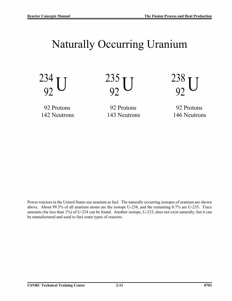
Naturally Occurring Uranium
92234 U 92 Protons142 Neutrons
92235 U 92 Protons143 Neutrons
92238 U 92 Protons146 Neutrons
Power reactors in the United States use uranium as fuel. The naturally occurring isotopes of uranium are shownabove. About 99.3% of all uranium atoms are the isotope U-238, and the remaining 0.7% are U-235. Traceamounts (far less than 1%) of U-234 can be found. Another isotope, U-233, does not exist naturally, but it canbe manufactured and used to fuel some types of reactors.

Reactor Concepts Manual The Fission Process and Heat Production
USNRC Technical Training Center 2-12 0703
ENRICHMENT(% U-235)
Uranium Ore (0.7%) Fuel Pellet (3.5%)
Uranium-235 (enriched from 0.7% abundance to 3.5% to 5%) is the fuel for most power reactors in the UnitedStates.

Reactor Concepts Manual The Fission Process and Heat Production
USNRC Technical Training Center 2-13 0703
Absorption
Fission
Uranium-235 is useful as a reactor fuel because:
1) It will readily absorb a neutron to become the highly unstable isotope U-236.
2) U-236 has a high probability of fission (about 80% of all U-236 atoms will fission).
3) The fission of U-236 releases energy (in the form of heat) which is used to produce high pressure steamand ultimately electricity.
4) The fission of U-236 releases two or three additional neutrons which can be used to cause other fissionsand establish a “chain reaction.”

Reactor Concepts Manual The Fission Process and Heat Production
USNRC Technical Training Center 2-14 0703
Birth
Thermalization
Absorption
Fuel Pellet Fuel
Rod
Moderator
H2O
Neutron Life Cycle
U-235 does have a high probability of absorbing a neutron. However, the probability increases even more if theneutron is moving slower. Therefore, in the reactor, it is desired to slow the neutrons down and then let the U-235 absorb them. This slowing down process is accomplished by the same water that is used to remove the heatfrom the fuel. Therefore, the water circulating through the reactor (called the reactor coolant system) has twoimportant functions. First, the water carries the heat from the reactor core to produce the steam used in theturbine. This prevents the fuel from becoming too hot, which could lead to fuel damage. Second, the water isused to control the fission process by slowing the neutrons down and by acting as a reflector to bounce back anyhigh energy neutrons that try to escape. This conserves the neutrons so that even more fissions may occur. The“slowing down” process is called “thermalization” or “moderation.”

Reactor Concepts Manual The Fission Process and Heat Production
USNRC Technical Training Center 2-15 0703
Fissions Y Heat
Controlling Fission Rate Y Controlling Heat Production Rate
Every fission releases a tiny amount of heat. Trillions of fissions per second are necessary to produce the hightemperature, high pressure steam for the production of electricity. The rate at which the uranium atoms arefissioned determines the rate at which heat (and power) are produced.

Reactor Concepts Manual The Fission Process and Heat Production
USNRC Technical Training Center 2-16 0703
Fission Chain Reaction
Since neutrons are necessary to cause the fission event, and since each fission releases neutrons, there is thepotential to set up a self-sustaining chain reaction. For this to occur, there must be sufficient material capableof fissioning, and the material must be arranged such that the neutrons will reach other fuel atoms beforeescaping.

Reactor Concepts Manual The Fission Process and Heat Production
USNRC Technical Training Center 2-17 0703
Criticality
Steady Rate of Power Generation
If the conditions in the core allow, the chain reaction will reach a state of being self-sustaining. At this point,for every fission event that occurs, a second event occurs. This point of equilibrium is known as “criticality.”This just means that the number of neutrons produced by the fission events is equal to the number of neutronsthat cause fission plus the number of neutrons that do not cause fission. Therefore, the reactor has reached a stateof equilibrium. That is, the amount of power, and therefore heat, being produced is constant with time.

Reactor Concepts Manual The Fission Process and Heat Production
USNRC Technical Training Center 2-18 0703
NEUTRONS THAT DO NOT CAUSEFISSIONS:
Leak out of the core, or
Are absorbed by neutron poisons
Because all neutrons that are produced by the fission process do not end up causing subsequent fissions, enoughneutrons must be produced to overcome the losses and to maintain the “critical” balance needed for a constantpower level. The neutrons that are lost to the fission process either “leak out” of the fuel area (escape) or areabsorbed by materials that do not fission. The materials that absorbed neutrons and do not fission are called“neutron poisons.”

Reactor Concepts Manual The Fission Process and Heat Production
USNRC Technical Training Center 2-19 0703
Shie
ld W
all
Rea
ctor
Ves
sel W
all
Con
trol R
od
Fuel Rods
Mod
erat
or (W
ater
)Some of the neutrons released by fission will “leak” out of the reactor core area to be absorbed by the denseconcrete shielding around the reactor vessel. All the neutrons that remain in the core area will be absorbed bythe materials from which the various core components are constructed (U-235, U-238, steel, control rods, etc.).

Reactor Concepts Manual The Fission Process and Heat Production
USNRC Technical Training Center 2-20 0703
Neutron Poisons:
Control RodsSoluble Boron
Fission ProductsUranium-238
Structural Components
Any material that absorbs neutrons and does not fission is a “poison” to the fission process. The reactor vessel,structural components, and the reactor coolant all absorb neutrons. Several fission products (the elements thatare formed from the splitting of the large U-235 nucleus) absorb neutrons (for example, xenon-135 andsamarium-149). Uranium-238 will sometimes fission after absorbing a fast neutron. When it does not, it acts asa neutron poison. These neutron poisons are uncontrollable by the operator.
Reactor operators can manipulate the total amount of poisons in the reactor by adjusting the position of thecontrol rods. Also, in a pressurized water reactor, the operator can adjust the amount of boron that is dissolvedin the reactor coolant. The control rods and the soluble boron are called controllable neutron poisons.
Reactor Concepts Manual The Fission Process and Heat Production
USNRC Technical Training Center 2-21 0703
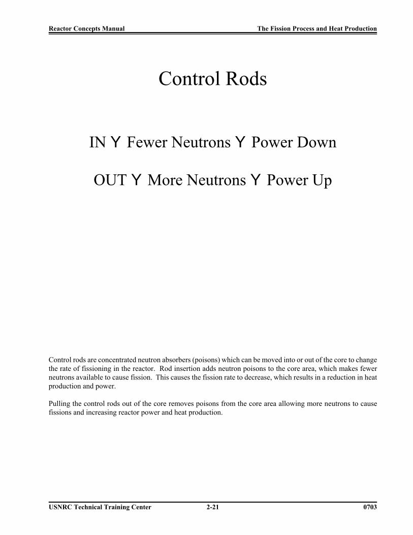
Control Rods
IN Y Fewer Neutrons Y Power Down
OUT Y More Neutrons Y Power Up
Control rods are concentrated neutron absorbers (poisons) which can be moved into or out of the core to changethe rate of fissioning in the reactor. Rod insertion adds neutron poisons to the core area, which makes fewerneutrons available to cause fission. This causes the fission rate to decrease, which results in a reduction in heatproduction and power.
Pulling the control rods out of the core removes poisons from the core area allowing more neutrons to causefissions and increasing reactor power and heat production.

Reactor Concepts Manual The Fission Process and Heat Production
USNRC Technical Training Center 2-22 0703
Moderator
Temperature/Density Relationship of Water
Moderator Temperature 8Y
Moderator Density 9Y
Neutron Leakage 8Y
Power Output 9
The use of water as a neutron moderator helps produce a steady rate of reactor power by slowing the neutronsdown that will be absorbed by the U-235 and by reflecting many of the neutrons that try to leak out of the reactorback into the core. The water can also remove neutrons from the fission chain.
First, water has a limited capacity to absorb neutrons, thus acting as a neutron poison. But an even greater effectis the changing of the moderator temperature. If the reactor coolant temperature increases, the water becomesless dense. This means that the water becomes less effective at slowing the neutrons down and more will leakout of the core. Conversely, if the coolant temperature decreases, the water becomes a better moderator, and thenumber of neutrons available for fission will increase. If the only action to occur was a change in the temperatureof the moderator, power would also change. This moderator temperature effect is a major factor in the controlof the fission process and heat production of the reactor.

Reactor Concepts Manual The Fission Process and Heat Production
USNRC Technical Training Center 2-23 0703
Voids (Steam Bubbles)
Moderator Void Content 8Y
Moderator Density 9Y
Neutron Leakage 8Y
Power Output 9
Since the moderator density plays such an important part in the control of the fission rate and the powerproduction in the reactor, the formation of steam bubbles, or “voids,” must also be considered. A steam bubbleis an area of very low density water.
In a boiling water reactor, the conversion of water into steam produces a dramatic change in the density of thewater from the bottom to the top of the core. Water at the bottom of the core is far more dense than the water-steam mixture at the top. Therefore, neutron moderation is much better towards the bottom of the core. In apressurized water reactor, the high pressure of the reactor coolant will prevent all but just a very minimumamount of steam bubbles from being formed. Therefore, the effects of voids on the power production in apressurized water reactor are very minimal.

Reactor Concepts Manual The Fission Process and Heat Production
USNRC Technical Training Center 2-24 0703
FissionProductDecay
Radiation
Decay Heat
Because of the unique properties of the nuclear fuel, there are some byproducts of the heat producing process.“Fission products” are the smaller atoms produced when the larger uranium atoms are split during the fissionprocess. Some of these fission products are neutron poisons, and therefore, must be compensated for byremoving some of the controllable poisons (such as the control rods for boiling water reactors or control rods orboron for pressurized water reactors) as they are produced. The fission products are usually very highlyradioactive. They emit a large amount of radiation, and therefore, must be contained within the plant. A systemof “barriers” has been developed to prevent these atoms from escaping into the environment. These barriers arethe fuel pellet and cladding, the reactor coolant system pressure boundary, and the containment.
Another problem with the fission products is the generation of decay heat. When an atom decays, it gives offenergy or particles to become more stable. The energy or particles then interact with the surroundings to generateheat. This heat will be collected inside the fuel pellet area. If this heat (decay heat) is not removed, it couldpossibly cause damage to the fuel pellets or other parts of the “barrier” system. Therefore, we have systemsdesigned to remove this heat after the plant is shut down (residual heat removal system, for example). Radiation,decay heat, and fission product barriers will all be discussed in subsequent sections of this manual.

Reactor Concepts Manual The Fission Process and Heat Production
USNRC Technical Training Center 2-25 0703
FuelPellet
Gap
600EFCoolant
600EFCoolant
1700EFFuel
Centerline
650EFCladding
750EFPellet
Surface
Fuel Rod and Coolant Temperatures
When a reactor is operating at full power, the approximate temperatures of the fuel centerline, pellet surface,cladding surface, and coolant are shown above. The average fuel pellet temperature under normal operatingconditions is about 1400EF. The melting temperature of the ceramic fuel is approximately 5200EF. The fuelcladding can be damaged by temperatures in excess of 1800EF. Significant fuel damage can be expected atsustained temperatures above 2200EF. The plant systems, both normal operating and emergency, must bedesigned to maintain the fuel temperature low enough to prevent fuel damage. For example, if conditionsapproach an operating limit, the reactor protection system will rapidly insert the control rods to shut down thefission chain, which removes a major heat production source. This rapid insertion of rods into the core is calleda reactor trip or scram.

Reactor Concepts Manual The Fission Process and Heat Production
USNRC Technical Training Center 2-26 0703
BWR
PWR
Reactor Scram (Trip)
Rapid Insertion of Control Rodsto Shutdown the Fission Chain Reaction
A reactor “scram” (or “trip”) is the rapid (two to four seconds) insertion of the control rods into the core to stopthe fission chain reaction. Even though all of the fissioning in the core is not stopped, the chain reaction isbroken down, which causes a significant decrease in reactor power in just a few seconds. When the reactor isshut down (all rods inserted), the amount of heat being generated due to the fissions which are not stopped andthe decay heat is much less than that which can be removed by the plant systems. Therefore, the fuel can beprotected from an over-temperature condition.
In a boiling water reactor, the control rods are inserted from the bottom of the reactor vessel into the core. In apressurized water reactor, the control rods are inserted (dropped) from the top of the reactor vessel into the core.

Reactor Concepts Manual Boiling Water Reactor Systems
USNRC Technical Training Center 3-1 0400
BoilingWater
Reactor(BWR)Systems
This chapter will discuss the purposes of some of the major systems and components associated witha boiling water reactor (BWR) in the generation of electrical power.

Reactor Concepts Manual Boiling Water Reactor Systems
USNRC Technical Training Center 3-2 0400
Jet Pump
ReactorVessel
SteamLine
Steam Dryer&
MoistureSeparator
Reactor Core
RecirculationPump
ThrottleValve
ElectricalGenerator
Turbine
Condenser
PumpContainment Suppression Chamber
Turbine Building
To/FromRiver
Containment/Drywell
Boiling Water Reactor Plant
Inside the boiling water reactor (BWR) vessel, a steam water mixture is produced when very pure water(reactor coolant) moves upward through the core absorbing heat. The major difference in the operationof a BWR from other nuclear systems is the steam void formation in the core. The steam-water mixtureleaves the top of the core and enters the two stages of moisture separation, where water droplets areremoved before the steam is allowed to enter the steam line. The steam line, in turn, directs the steamto the main turbine causing it to turn the turbine and the attached electrical generator. The unused steamis exhausted to the condenser where it is condensed into water. The resulting water is pumped out ofthe condenser with a series of pumps and back to the reactor vessel. The recirculation pumps and jetpumps allow the operator to vary coolant flow through the core and change reactor power.

Reactor Concepts Manual Boiling Water Reactor Systems
USNRC Technical Training Center 3-3 0400
BWR Reactor Vessel Assembly
The reactor vessel assembly, shown on page 3-4, consists of the reactor vessel and its internalcomponents, including the core support structures, core shroud, moisture removal equipment, and jetpump assemblies. The purposes of the reactor vessel assembly are to:
• House the reactor core,• Serve as part of the reactor coolant pressure boundary,• Support and align the fuel and control rods,• Provide a flow path for circulation of coolant past the fuel,• Remove moisture from the steam exiting the core, and• Provide a refloodable volume for a loss of coolant accident.
The reactor vessel is vertically mounted within the drywell and consists of a cylindrical shell with anintegral rounded bottom head. The top head is also rounded in shape but is removable via the stud andnut arrangement to facilitate refueling operations. The vessel assembly is supported by the vesselsupport skirt (20) which is mounted to the reactor vessel support pedestal.
The internal components of the reactor vessel are supported from the bottom head and/or vessel wall.The reactor core is made up of fuel assemblies (15), control rods (16), and neutron monitoringinstruments (24). The structure surrounding the active core consists of a core shroud (14), core plate(17), and top guide (12). The components making up the remainder of the reactor vessel internals arethe jet pump assemblies (13), steam separators (6), steam dryers (3), feedwater spargers (8), and corespray spargers (11). The jet pump assemblies are located in the region between the core shroud and thevessel wall, submerged in water. The jet pump assemblies are arranged in two semicircular groups often, with each group being supplied by a separate recirculation pump.
The emergency core cooling systems, penetrations number 5 and 9, and the reactor vessel designs arecompatible to ensure that the core can be adequately cooled following a loss of reactor coolant. Theworst case loss of coolant accident, with respect to core cooling, is a recirculation line break(penetrations number 18 and 19). In this event, reactor water level decreases rapidly, uncovering thecore. However, several emergency core cooling systems automatically provide makeup water to thenuclear core within the shroud, providing core cooling.
The control cell assembly (page 3-5) is representative for boiling water reactor 1 through 6. Each controlcell consists of a control rod (7) and four fuel assemblies that surround it. Unlike the pressurized waterreactor fuel assemblies, the boiling water reactor fuel bundle is enclosed in a fuel channel (6) to directcoolant up through the fuel assembly and act as a bearing surface for the control rod. In addition, thefuel channel protects the fuel during refueling operations. The power of the core is regulated bymovement of bottom entry control rods.

Reactor Concepts Manual Boiling Water Reactor Systems
USNRC Technical Training Center 3-4 0400
BWR 6 Reactor Vessel

Reactor Concepts Manual Boiling Water Reactor Systems
USNRC Technical Training Center 3-5 0400
BWR 6 Fuel Assembly

Reactor Concepts Manual Boiling Water Reactor Systems
USNRC Technical Training Center 3-6 Rev 0200
SteamDryer
Assembly
ReactorCore
Containment/Drywell
Main Steam Line
Main Feedwater Line
Recirculation Loop(Typical of 2)
RecirculationPump
Containment Suppression Chamber
SteamSeparatorAssembly
Safety/Relief Valve
Reactor WaterCleanup Pump
To Main Turbine
Filter/Demineralizer
Reactor Building Cooling Water
Non-RegenerativeHeat Exchanger
RegenerativeHeat Exchanger
Reactor Water Cleanup System
The purpose of the reactor water cleanup system (RWCU) is to maintain a high reactor water quality byremoving fission products, corrosion products, and other soluble and insoluble impurities. The reactorwater cleanup pump takes water from the recirculation system and the vessel bottom head and pumpsthe water through heat exchangers to cool the flow. The water is then sent through filter/demineralizersfor cleanup. After cleanup, the water is returned to the reactor vessel via the feedwater piping.

Reactor Concepts Manual Boiling Water Reactor Systems
USNRC Technical Training Center 3-7 Rev 0200
Jet Pump
ReactorVessel
SteamLine
SteamDryer
Assembly
ReactorCore
RecirculationPump
ElectricalGenerator
Containment Suppression Chamber
To/FromRiver
Containment/Drywell
TurbineBypass
Line
Service Water
Residual Heat RemovalHeat ExchangerResidual Heat
Removal Pump
Decay Heat Removal
Heat is removed during normal power operation by generating steam in the reactor vessel and then usingthat steam to generate electrical energy. When the reactor is shutdown, the core will still continue togenerate decay heat. The heat is removed by bypassing the turbine and dumping the steam directly tothe condenser. The shutdown cooling mode of the residual heat removal (RHR) system is used tocomplete the cooldown process when pressure decreases to approximately 50 psig. Water is pumpedfrom the reactor recirculation loop through a heat exchanger and back to the reactor via the recirculationloop. The recirculation loop is used to limit the number of penetrations into the reactor vessel.
Reactor Concepts Manual Boiling Water Reactor Systems
USNRC Technical Training Center 3-8 Rev 0200
SteamDryer
Assembly
ReactorCore
Containment/Drywell
Main Steam Line
Main Feedwater Line
Recirculation Loop(Typical of 2)
RecirculationPump
Containment Suppression Chamber
SteamSeparatorAssembly
Safety/Relief Valve
RCICPump
RCICTurbine
To Main Turbine
CondensateStorage Tank
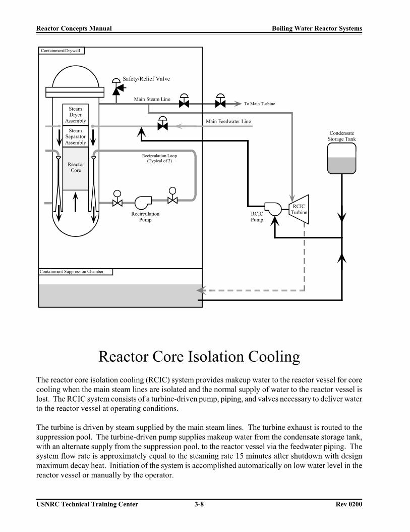
Reactor Core Isolation CoolingThe reactor core isolation cooling (RCIC) system provides makeup water to the reactor vessel for corecooling when the main steam lines are isolated and the normal supply of water to the reactor vessel islost. The RCIC system consists of a turbine-driven pump, piping, and valves necessary to deliver waterto the reactor vessel at operating conditions.
The turbine is driven by steam supplied by the main steam lines. The turbine exhaust is routed to thesuppression pool. The turbine-driven pump supplies makeup water from the condensate storage tank,with an alternate supply from the suppression pool, to the reactor vessel via the feedwater piping. Thesystem flow rate is approximately equal to the steaming rate 15 minutes after shutdown with designmaximum decay heat. Initiation of the system is accomplished automatically on low water level in thereactor vessel or manually by the operator.

Reactor Concepts Manual Boiling Water Reactor Systems
USNRC Technical Training Center 3-9 Rev 0200
SteamDryer
Assembly
ReactorCore
Containment/Drywell
Main Steam Line
Main Feedwater Line
Recirculation Loop(Typical of 2)
RecirculationPump
Containment Suppression Chamber
SteamSeparatorAssembly
To Main Turbine
Poison Tank(Boron)
ExplosiveValve
Standby Liquid Control System
The standby liquid control system injects a neutron poison (boron) into the reactor vessel to shutdownthe chain reaction, independent of the control rods, and maintains the reactor shutdown as the plant iscooled to maintenance temperatures.
The standby liquid control system consists of a heated storage tank, two positive displacement pumps,two explosive valves, and the piping necessary to inject the neutron absorbing solution into the reactorvessel. The standby liquid control system is manually initiated and provides the operator with arelatively slow method of achieving reactor shutdown conditions.

Reactor Concepts Manual Boiling Water Reactor Systems
USNRC Technical Training Center 3-10 Rev 0200
Emergency Core Cooling Systems
The emergency core cooling systems (ECCS) provide core cooling under loss of coolant accidentconditions to limit fuel cladding damage. The emergency core cooling systems consist of two highpressure and two low pressure systems. The high pressure systems are the high pressure coolantinjection (HPCI) system and the automatic depressurization system (ADS). The low pressure systemsare the low pressure coolant injection (LPCI) mode of the residual heat removal system and the corespray (CS) system.
The manner in which the emergency core cooling systems operate to protect the core is a function of therate at which reactor coolant inventory is lost from the break in the nuclear system process barrier. Thehigh pressure coolant injection system is designed to operate while the nuclear system is at high pressure.The core spray system and low pressure coolant injection mode of the residual heat removal system aredesigned for operation at low pressures. If the break in the nuclear system process barrier is of such asize that the loss of coolant exceeds the capability of the high pressure coolant injection system, reactorpressure decreases at a rate fast enough for the low pressure emergency core cooling systems tocommence coolant injection into the reactor vessel in time to cool the core.
Automatic depressurization is provided to automatically reduce reactor pressure if a break has occurredand the high pressure coolant injection system is inoperable. Rapid depressurization of the reactor isdesirable to permit flow from the low pressure emergency core cooling systems so that the temperaturerise in the core is limited to less than regulatory requirements.
If, for a given break size, the high pressure coolant injection system has the capacity to make up for allof the coolant loss, flow from the low pressure emergency core cooling systems is not required for corecooling protection until reactor pressure has decreased below approximately 100 psig.
The performance of the emergency core cooling systems as an integrated package can be evaluated bydetermining what is left after the postulated break and a single failure of one of the emergency corecooing systems. The remaining emergency core cooling systems and components must meet the 10 CFRrequirements over the entire spectrum of break locations and sizes. The integrated performance forsmall, intermediate, and large sized breaks is shown on pages 3-11 and 3-12.

Reactor C
oncepts Manual
Boiling W
ater Reactor System
s
USN
RC
Technical T
raining Center
3-11R
ev 0200
ADS
HPCISystem
CoreCooling
Achieved
ECCS Integrated Performance
HPCISystem
AnyRHRPump
System1
CS
System2
CS ADS
Small Break Only
AnyRHRPump
System1
CS
System2
CS
Remaining ECCS SingleFailure
Small orIntermediateBreak LOCA
Remaining ECCS
System2
CS
System1
CS
System2(1)RHR
System1(2)RHR
SingleFailure
System2
RHR
System1
RHR
System2(1)CS
System1(2)CS
LargeBreakLOCA

Reactor Concepts Manual Boiling Water Reactor Systems
USNRC Technical Training Center 3-12 Rev 0200
Feedwater Line
Steam Line
ToSuppression
Pool
ADS
T
HPCI System
DieselGenerator
A
Shutdown Board
DieselGenerator
A
Shutdown Board
A
A
C
C
B
D
D
B
RHRSystem 1
RecirculationPump B
RecirculationPump A
Core SpraySystem 1
Core SpraySystem 2
RHRSystem 2
ReactorVessel
Emergency Core Cooling System Network

Reactor Concepts Manual Boiling Water Reactor Systems
USNRC Technical Training Center 3-13 Rev 0200
SteamDryer
Assembly
ReactorCore
Containment/Drywell
Main Steam Line
Main Feedwater Line
Recirculation Loop(Typical of 2)
RecirculationPump
Containment Suppression Chamber
SteamSeparatorAssembly
Safety/Relief Valve
HPCIPump
HPCITurbine
To Main Turbine
CondensateStorage Tank
High Pressure Emergency Core Cooling Systems
The high pressure coolant injection (HPCI) system is an independent emergency core cooling systemrequiring no auxiliary ac power, plant air systems, or external cooling water systems to perform itspurpose of providing make up water to the reactor vessel for core cooling under small and intermediatesize loss of coolant accidents. The high pressure coolant injection system can supply make up water tothe reactor vessel from above rated reactor pressure to a reactor pressure below that at which the lowpressure emergency core cooling systems can inject.
The automatic depressurization system (ADS) consists of redundant logics capable of opening selectedsafety relief valves, when required, to provide reactor depressurization for events involving small orintermediate size loss of coolant accidents if the high pressure coolant injection system is not availableor cannot recover reactor vessel water level.

Reactor Concepts Manual Boiling Water Reactor Systems
USNRC Technical Training Center 3-14 Rev 0200
SteamDryer
Assembly
ReactorCore
Containment/DrywellContainment Spray
Main Steam Line
Main Feedwater Line
Recirculation Loop(Typical of 2)
Jet Pump
RecirculationPump
Containment Spray
LPCI
Containment Suppression Chamber
RHRHeat
Exchanger
Service Water
RHR Pumps(LPCI Mode)
Core SprayPump
Low Pressure Emergency Core Cooling Systems
The low pressure emergency core cooling systems consist of two separate and independent systems, thecore spray system and the low pressure coolant injection (LPCI) mode of the residual heat removalsystem. The core spray system consists of two separate and independent pumping loops, each capableof pumping water from the suppression pool into the reactor vessel. Core cooling is accomplished byspraying water on top of the fuel assemblies.
The low pressure coolant injection mode of the residual heat removal system provides makeup water tothe reactor vessel for core cooling under loss of coolant accident conditions. The residual heat removalsystem is a multipurpose system with several operational modes, each utilizing the same major piecesof equipment. The low pressure coolant injection mode is the dominant mode and normal valve lineupconfiguration of the residual heat removal system. The low pressure coolant injection mode operatesautomatically to restore and, if necessary, maintain the reactor vessel coolant inventory to preclude fuelcladding temperatures in excess of 2200EF. During low pressure coolant injection operation, the residualheat removal pumps take water from the suppression pool and discharge to the reactor vessel.

Reactor Concepts Manual Boiling Water Reactor Systems
USNRC Technical Training Center 3-15 Rev 0200
Boiling Water Reactor Containments
The primary containment package provided for a particular product line is dependent upon the vintageof the plant and the cost-benefit analysis performed prior to the plant being built. During the evolutionof the boiling water reactors, three major types of containments were built. The major containmentdesigns are the Mark I (page 3-16), Mark II (page 3-17), and the Mark III (page 3-18). Unlike the MarkIII, that consists of a primary containment and a drywell, the Mark I and Mark II designs consist of adrywell and a wetwell (suppression pool). All three containment designs use the principle of pressuresuppression for loss of coolant accidents. The primary containment is designed to condense steam andto contain fission products released from a loss of coolant accident so that offsite radiation dosesspecified in 10 CFR 100 are not exceeded and to provide a heat sink and water source for certain safety-related equipment.
The Mark I containment design consists of several major components, many of which can be seen onpage 3-16. These major components include:
• The drywell, which surrounds the reactor vessel and recirculation loops,• A suppression chamber, which stores a large body of water (suppression pool),• An interconnecting vent network between the drywell and the suppression chamber, and• The secondary containment, which surrounds the primary containment (drywell and suppression
pool) and houses the spent fuel pool and emergency core cooling systems.
The Mark II primary containment consists of a steel dome head and either a post-tensioned concrete wallor reinforced concrete wall standing on a base mat of reinforced concrete. The inner surface of thecontainment is lined with a steel plate that acts as a leak-tight membrane. The containment wall alsoserves as a support for the floor slabs of the reactor building (secondary containment) and the refuelingpools. The Mark II design is an over-under configuration. The drywell, in the form of a frustum of acone or a truncated cone, is located directly above the suppression pool. The suppression chamber iscylindrical and separated from the drywell by a reinforced concrete slab. The drywell is topped by anelliptical steel dome called a drywell head. The drywell inerted atmosphere is vented into thesuppression chamber through as series of downcomer pipes penetrating and supported by the drywellfloor.
The Mark III primary containment consists of several major components, many of which can be seen onpage 3-18. The drywell (13) is a cylindrical, reinforced concrete structure with a removable head. Thedrywell is designed to withstand and confine steam generated during a pipe rupture inside thecontainment and to channel the released steam into the suppression pool (10) via the weir wall (11) andthe horizontal vents (12). The suppression pool contains a large volume of water for rapidly condensingsteam directed to it. A leak tight, cylindrical, steel containment vessel (2) surround the drywell and thesuppression pool to prevent gaseous and particulate fission products from escaping to the environmentfollowing a pipe break inside containment.

Reactor Concepts Manual Boiling Water Reactor Systems
USNRC Technical Training Center 3-16 Rev 0200
Mark I Containment

Reactor Concepts Manual Boiling Water Reactor Systems
USNRC Technical Training Center 3-17 Rev 0200
Mark II Containment

Reactor C
oncepts Manual
Boiling W
ater Reactor System
s
USN
RC
Technical T
raining Center
3-18R
ev 0200
Mark III C
ontainment

Reactor Concepts Manual Pressurized Water Reactor Systems
USNRC Technical Training Center 4-1 0603
PressurizedWater
Reactor(PWR)
Systems
For a nuclear power plant to perform the function of generating electricity, many different systems mustperform their functions. These functions may range from the monitoring of a plant parameter to thecontrolling of the main turbine or the reactor. This chapter will discuss the purposes of some of themajor systems and components associated with a pressurized water reactor.

Reactor Concepts Manual Pressurized Water Reactor Systems
USNRC Technical Training Center 4-2 0603
C O R E
S/G
RCP
AUXILIARY BUILDING
RHRHX
CONTAINMENTSUMP
CONTAINMENT BUILDING
PZR
REACTORCOOLANT SYSTEM
TURBINE BUILDING
FWHTR
MSR
HP LP
MAINCONDENSER
ELECTRICGENERATOR
COOLING TOWER
CIRC. WATERPUMP
RHRPUMP
MAINTURBINE
CONDENSATEPUMP
MAIN FEEDPUMP
There are two major systems utilized to convert the heat generated in the fuel into electrical power forindustrial and residential use. The primary system transfers the heat from the fuel to the steam generator,where the secondary system begins. The steam formed in the steam generator is transferred by thesecondary system to the main turbine generator, where it is converted into electricity. After passingthrough the low pressure turbine, the steam is routed to the main condenser. Cool water, flowingthrough the tubes in the condenser, removes excess heat from the steam, which allows the steam tocondense. The water is then pumped back to the steam generator for reuse.
In order for the primary and secondary systems to perform their functions, there are approximately onehundred support systems. In addition, for emergencies, there are dedicated systems to mitigate theconsequences of accidents.

Reactor Concepts Manual Pressurized Water Reactor Systems
USNRC Technical Training Center 4-3 0603
PRESSURIZER
REACTOR
STEAMGENERATOR
REACTORCOOLANT
PUMP
The primary system (also called the Reactor Coolant System) consists of the reactor vessel, the steamgenerators, the reactor coolant pumps, a pressurizer, and the connecting piping. A reactor coolant loopis a reactor coolant pump, a steam generator, and the piping that connects these components to thereactor vessel. The primary function of the reactor coolant system is to transfer the heat from the fuelto the steam generators. A second function is to contain any fission products that escape the fuel.
The following drawings show the layout of the reactor coolant systems for three pressurized waterreactor vendors. All of the systems consist of the same major components, but they are arranged inslightly different ways. For example, Westinghouse has built plant with two, three, or four loops,depending upon the power output of the plant. The Combustion Engineering plants and the Babcock& Wilcox plants only have two steam generators, but they have four reactor coolant pumps.

Reactor Concepts Manual Pressurized Water Reactor Systems
USNRC Technical Training Center 4-4 0603
REACTORCOOLANT
PUMP
PRESSURIZER
STEAMGENERATOR
REACTOR
A two-loop Westinghouse plant has two steam generators, two reactor coolant pumps, and a pressurizer.The two-loop units in the United States are Ginna, Kewaunee, Point Beach 1 and 2, and Prairie Island1 and 2. Each of these plants has 121, 14 x 14 fuel assemblies arranged inside a reactor vessel that hasan internal diameter of 132 inches. The electrical output of these plants is approximately 500 megawatts.

Reactor Concepts Manual Pressurized Water Reactor Systems
USNRC Technical Training Center 4-5 0603
STEAMGENERATOR
PRESSURIZER
MAINCOOLANT
PUMP
REACTOR
A three-loop Westinghouse plant has three steam generators, three reactor coolant pumps, and apressurizer. The three-loop units in the United States are Beaver Valley 1 and 2, Farley 1 and 2, H. B.Robinson 2, North Anna 1 and 2, Shearon Harris 1, V. C. Summer, Surry 1 and 2, and Turkey Point 3and 4. Each of these plants has 157 fuel assemblies. Some units use 15 x 15 fuel assemblies whileothers use 17 x 17 arrays. The reactor vessels have internal diameters of 156 to 159 inches, exceptSummer and Turkey Point, which have 172-inch reactor vessels. The electrical output of these plantsvaries from almost 700 to more than 900 megawatts.

Reactor Concepts Manual Pressurized Water Reactor Systems
USNRC Technical Training Center 4-6 0603
STEAM GENERATOR
MAIN COOLANT PUMP
PRESSURIZER
REACTOR
A four-loop Westinghouse plant has four steam generators, four reactor coolant pumps, and apressurizer. The four-loop units in the United States are Braidwood 1 and 2, Byron 1 and 2, Callaway,Catawba 1 and 2, Comanche Peak 1 and 2, D. C. Cook 1 and 2, Diablo Canyon 1 and 2, Indian Point 2and 3, McGuire 1 and 2, Millstone 3, Salem 1 and 2, Seabrook, Sequoyah 1 and 2, South Texas Project1 and 2, Vogtle 1 and 2, Watts Bar 1, and Wolf Creek. Each of these plants has 193 fuel assembliesarranged inside a reactor vessel that has an internal diameter of 173 inches (except South Texas has aninternal diameter of 167 inches). The fuel assemblies are arranged in 17 x 17 array except for Cook andIndian Point, which have 15 x 15 fuel. The electrical output of these plants ranges from 950 to 1250megawatts.

Reactor Concepts Manual Pressurized Water Reactor Systems
USNRC Technical Training Center 4-7 0603
A Babcock & Wilcox plant has two once through steam generators, four reactor coolant pumps, and apressurizer. The Babcock & Wilcox units in the United States are Arkansas 1, Crystal River 3, DavisBesse, Oconee 1, 2, and 3, and Three Mile Island 1. Each of these plants has 177 fuel assemblies. Theelectrical output of these plants is approximately 850 megawatts.

Reactor Concepts Manual Pressurized Water Reactor Systems
USNRC Technical Training Center 4-8 0603
STEAMGENERATOR
No. 1
PUMPNo. 1B
PUMPNo. 1A
PUMPNo. 2A
PUMPNo. 2B
STEAMGENERATOR
No. 2
REACTORVESSEL
PRESSURIZER
A Combustion Engineering plant has two steam generators, four reactor coolant pumps, and apressurizer. The Combustion Engineering units in the United States are Arkansas 2, Calvert Cliffs 1 and2, Fort Calhoun, Millstone 2, Palisades, Palo Verde 1, 2, and 3, San Onofre 2 and 3, Saint Lucie 1 and2, and Waterford 3. The electrical output of these plants varies from less than 500 to more than 1200megawatts.

Reactor Concepts Manual Pressurized Water Reactor Systems
USNRC Technical Training Center 4-9 0603
Reactor VesselThe reactor core, and all associated support and alignment devices, are housed within the reactor vessel(cutaway view on page 4-10). The major components are the reactor vessel, the core barrel, the reactorcore, and the upper internals package.
The reactor vessel is a cylindrical vessel with a hemispherical bottom head and a removablehemispherical top head. The top head is removable to allow for the refueling of the reactor. There willbe one inlet (or cold leg) nozzle and one outlet (or hot leg) nozzle for each reactor coolant system loop.The reactor vessel is constructed of a manganese molybdenum steel, and all surfaces that come intocontact with reactor coolant are clad with stainless steel to increase corrosion resistance.
The core barrel slides down inside of the reactor vessel and houses the fuel. Toward the bottom of thecore barrel, there is a lower core support plate on which the fuel assemblies sit. The core barrel and allof the lower internals actually hang inside the reactor vessel from the internals support ledge. On theoutside of the core barrel will be irradiation specimen holders in which samples of the material used tomanufacture the vessel will be placed. At periodic time intervals, some of these samples will beremoved and tested to see how the radiation from the fuel has affected the strength of the material.
The upper internals package sits on top of the fuel. It contains the guide columns to guide the controlrods when they are pulled from the fuel. The upper internals package prevents the core from trying tomove up during operation due to the force from the coolant flowing through the assemblies.
The flow path for the reactor coolant through the reactor vessel would be:
• The coolant enters the reactor vessel at the inlet nozzle and hits against the core barrel.
• The core barrel forces the water to flow downward in the space between the reactor vessel walland the core barrel.
• After reaching the bottom of the reactor vessel, the flow is turned upward to pass through the fuelassemblies.
• The coolant flows all around and through the fuel assemblies, removing the heat produced by thefission process.
• The now hotter water enters the upper internals region, where it is routed out the outlet nozzleand goes on to the steam generator.

Reactor Concepts Manual Pressurized Water Reactor Systems
USNRC Technical Training Center 4-10 0603
ROD TRAVELHOUSING
INSTRUMENTATIONPORTS
THERMAL SLEEVE
LIFTING LUG
CLOSURE HEADASSEMBLY
HOLD-DOWN SPRING
CONTROL RODGUIDE TUBE
CONTROL RODDRIVE SHAFT
INLET NOZZLE
CONTROL RODCLUSTER (WITHDRAWN)
ACCESS PORT
REACTOR VESSEL
LOWER CORE PLATE
CONTROL RODDRIVE MECHANISM
UPPER SUPPORTPLATE
INTERNALSSUPPORT
LEDGE
CORE BARREL
SUPPORT COLUMN
UPPER COREPLATE
OUTLET NOZZLE
BAFFLE RADIALSUPPORT
BAFFLE
CORE SUPPORTCOLUMNS
INSTRUMENTATIONTHIMBLE GUIDES
RADIAL SUPPORT
CORE SUPPORT
Cutaway View of Reactor Vessel

Reactor Concepts Manual Pressurized Water Reactor Systems
USNRC Technical Training Center 4-11 0603
Steam GeneratorsThe reactor coolant flows from the reactor to the steam generator. Inside of the steam generator, the hotreactor coolant flows inside of the many tubes. The secondary coolant, or feedwater, flows around theoutside of the tubes, where it picks up heat from the primary coolant. When the feedwater absorbssufficient heat, it starts to boil and form steam. At this point, the steam generators used by the threePressurized Water Reactor vendors differ slightly in their designs and operations.
In the Westinghouse (page 4-12) and Combustion Engineering (page 4-13) designs, the steam/watermixture passes through multiple stages of moisture separation. One stage causes the mixture to spin,which slings the water to the outside. The water is then drained back to be used to make more steam.The drier steam is routed to the second stage of separation. In this stage, the mixture is forced to makerapid changes in direction. Because of the steam’s ability to change direction and the water’s inabilityto change, the steam exits the steam generator, and the water is drained back for reuse. The two stageprocess of moisture removal is so efficient at removing the water that for every 100 pounds of steam thatexits the steam generator, the water content is less than 0.25 pounds. It is important to maintain themoisture content of the steam as low as possible to prevent damage to the turbine blading.
The Babcock & Wilcox design uses a once through steam generator (OTSG, page 4-14). In this design,the flow of primary coolant is from the top of the steam generator to the bottom, instead of through U-shaped tubes as in the Westinghouse and Combustion Engineering designs. Because of the heat transferachieved by this design, the steam that exits the once through steam generator contains no moisture.This is done by heating the steam above the boiling point, or superheating.
Other differences in design include the ways in which the steam and the cooler primary coolant exit thesteam generators. In a Westinghouse steam generator, there is a single outlet fro the steam and a singleoutlet for the primary coolant. For both the Babcock & Wilcox design and the Combustion Engineeringdesign there are two steam outlets and two primary coolant outlets.
For all of the steam generator designs, the steam is piped to the main turbine, and the coolant is routedto the suction of the reactor coolant pumps.

Reactor Concepts Manual Pressurized Water Reactor Systems
USNRC Technical Training Center 4-12 0603
DEMISTERS SECONDARYMOISTURE SEPARATOR
ORFICE RINGS
SWIRL VANE PRIMARYMOISTURE
SEPARATOR
FEEDWATER INLET
ANTIVIBRATION BARS
WRAPPER
TUBE SUPPORT PLATES
BLOWDOWNLINE
TUBE SHEET
PRIMARY MANWAY
PRIMARY COOLANT INLET
STEAM OUTLET TO TURBINEGENERATOR
SECONDARYMANWAY
UPPER SHELL
FEEDWATER RING
TUBE BUNDLE
LOWERSHELL
SECONDARY HANDHOLE
TUBE LANEBLOCK
PRIMARY COOLANT OUTLET
Cutaway View of A Westinghouse Steam Generator

Reactor Concepts Manual Pressurized Water Reactor Systems
USNRC Technical Training Center 4-13 0603
STEAMDRUM
126 STEAMDRYERS
166 STEAMSEPARATORS
SECONDARYMANWAY (2)
RISER NORMALWATERLEVEL
AUXILIARYFEEDWATER
NOZZLE
STEAMOUTLET
DEFLECTOR
32 STEAMDRYER DRAINS
INSTRUMENTNOZZLE
RECIRCULATIONSUMP
RECIRCULATIONSUMP DRAINS
MAIN FEEDWATERNOZZLE
MAIN FEED RING
INSTRUMENTNOZZLE
BATWING
EGG CRATESUPPORTS
VERTICLEU-TUBES
BOTTOM BLOWDOWN& DRAIN NOZZLE
COLD LEGOUTLET (2)HOT LEG
INLET
TUBESHEET
SECONDARYHANDHOLE (2)
EVAPORATOR(TUBE BUNDLE)
TUBEWRAPPER
Cutaway View of a Combustion Engineering Steam Generator

Reactor Concepts Manual Pressurized Water Reactor Systems
USNRC Technical Training Center 4-14 0603
36" INSIDE DIAMETER PRIMARY INLET NOZZLE
(32) FEEDWATER INLETS
(2) OPERATING RANGELOW LEVEL SENSING
CONNECTIONS
16" INSIDE DIAMETER MANWAY(8) 3' 3/4" x 30" WATER PORTS
16" INSIDE DIAMETER MANWAY
1" DRAIN CONNECTION(2) 28" INSIDE DIAMETER PRIMARYOUTLET NOZZLES
(4) 1-1/2"DRAIN
(2) STARTUP & FULL RANGELOWER INSTRUMENT TAPS
(2) SAMPLING DRAINS
(2) TEMP. SENSING CONNECTIONS
14" OUTSIDE DIAMETERFEEDWATER HEADERS
(2) OPERATING ANDSTARTUP RANGE
UPPER INSTRUMENT TAPS
(2) 24" STEAMOUTLET NOZZLES
(6) EMERGENCYFEEDWATER NOZZLES
(1) VENT & FULL RANGEUPPER INSTRUMENT TAP
16" INSIDE DIAMETERMANWAY
Cutaway View of a Babcock & Wilcox Once Through Steam Generator

Reactor Concepts Manual Pressurized Water Reactor Systems
USNRC Technical Training Center 4-15 0603
Reactor Coolant PumpThe purpose of the reactor coolant pump is to provide forced primary coolant flow to remove the amountof heat being generated by the fission process. Even without a pump, there would be natural circulationflow through the reactor. However, this flow is not sufficient to remove the heat being generated whenthe reactor is at power. Natural circulation flow is sufficient for heat removal when the plant isshutdown (not critical).
The reactor coolant enters the suction side of the pump from the outlet of the steam generator. The wateris increased in velocity by the pump impeller. This increase in velocity is converted to pressure in thedischarge volute. At the discharge of the reactor coolant pump, the reactor coolant pressure will beapproximately 90 psi higher than the inlet pressure.
After the coolant leaves the discharge side of the pump, it will enter the inlet or cold leg side of thereactor vessel. The coolant will then pass through the fuel to collect more heat and is sent back to thesteam generators.
The major components of a reactor coolant pump (page 4-16) are the motor, the hydraulic section, andthe seal package.
The motor is a large, air cooled, electric motor. The horsepower rating of the motor will be from 6,000to 10,000 horsepower. This large amount of power is needed in order to provide the necessary flow ofcoolant for heat removal (approximately 100,000 gallons per minute per pump).
The hydraulic section of the pump is the impeller and the discharge volute. The impeller of the pumpis attached to the motor by a long shaft.
The seal package is located between the motor and the hydraulic section and prevents any water fromleaking up the shaft into the containment atmosphere. Any water that does leak up the shaft is collectedand routed to the seal leakoff system for collection in various systems.

Reactor Concepts Manual Pressurized Water Reactor Systems
USNRC Technical Training Center 4-16 0603
THRUST BEARINGOIL LIFT PUMP
+ MOTOR
MOTOR UNIT ASSEMBLY
SEAL HOUSING
NO. 1 SEAL LEAK OFF
MAIN FLANGE
COOLING WATEROUTLET
RADIAL BEARINGASSEMBLY
THERMAL BARRIER ANDHEAT EXCHANGER
CASING
IMPELLER
FLYWHEEL
UPPER RADIALBEARING
THRUST BEARING
MOTOR SHAFT
MOTOR STATOR
MAIN LEADCONDUIT BOX
LOWER RADIALBEARING
NO. 3 SEALLEAK OFF
NO. 2 SEALLEAK OFF
PUMP SHAFT
COOLANT WATER INLET
DISCHARGENOZZLE
SUCTIONNOZZLE
Cutaway View of a Reactor Coolant Pump

Reactor Concepts Manual Pressurized Water Reactor Systems
USNRC Technical Training Center 4-17 0603
PressurizerThe pressurizer (page 4-18) is the component in the reactor coolant system which provides a means ofcontrolling the system pressure. Pressure is controlled by the use of electrical heaters, pressurizer spray,power operated relief valves, and safety valves.
The pressurizer operates with a mixture of steam and water in equilibrium. If pressure starts to deviatefrom the desired value, the various components will actuate to bring pressure back to the normaloperating point. The cause of the pressure deviation is normally associated with a change in thetemperature of the reactor coolant system. If reactor coolant system temperature starts to increase, thedensity of the reactor coolant will decrease, and the water will take up more space. Since the pressurizeris connected to the reactor coolant system via the surge line, the water will expand up into thepressurizer. This will cause the steam in the top of the pressurizer to be compressed, and therefore, thepressure to increase.
The opposite effect will occur if the reactor coolant system temperature decreases. The water willbecome more dense, and will occupy less space. The level in the pressurizer will decrease, which willcause a pressure decrease. For a pressure increase or decrease, the pressurizer will operate to bringpressure back to normal.
For example, if pressure starts to increase above the desired setpoint, the spray line will allow relativelycold water from the discharge of the reactor coolant pump to be sprayed into the steam space. The coldwater will condense the steam into water, which will reduce pressure (due to the fact that steam takesup about six times more space than the same mass of water). If pressure continues to increase, thepressurizer relief valves will open and dump steam to the pressurizer relief tank. If this does not relievepressure, the safety valves will lift, also discharging to the pressurizer relief tank.
If pressure starts to decrease, the electrical heaters will be energized to boil more water into steam, andtherefore increase pressure. If pressure continues to decrease, and reaches a predetermined setpoint, thereactor protection system will trip the reactor.
The pressurizer relief tank (page 4-19) is a large tank containing water with a nitrogen atmosphere. Thewater is there to condense any steam discharged by the safety or relief valves. Since the reactor coolantsystem contains hydrogen, the nitrogen atmosphere is used to prevent the hydrogen from existing in apotentially explosive environment.

Reactor Concepts Manual Pressurized Water Reactor Systems
USNRC Technical Training Center 4-18 0603
RELIEFNOZZLE
HEATER SUPPORTPLATE
SURGE NOZZLE
SUPPORT SKIRT
ELECTRICAL HEATER
INSTRUMENTATIONNOZZLE
LOWER HEAD
SHELL
LIFTINGTRUNNION
(LOAN BASIS)
INSTRUMENTATIONNOZZLE
UPPER HEAD
MANWAY
SAFETY NOZZLE
SPRAY NOZZLE
Cutaway View of a Pressurizer

Reactor Concepts Manual Pressurized Water Reactor Systems
USNRC Technical Training Center 4-19 0603
RCS
RCS
SPRAYVALVES
SAFETIES
RELIEFS
PRESSURIZER
HEATERS
SURGE LINE
REACTOR COOLANTSYSTEM (RCS)
PRESSURIZERRELIEF TANK
DRAIN
VENT
COOLINGSPRAY
Pressurizer and Pressurizer Relief Tank

Reactor Concepts Manual Pressurized Water Reactor Systems
USNRC Technical Training Center 4-20 0603
REACTOR COOLANTSYSTEM
CONTAINMENT
CORE
S/G
PZR
RCP
CONTAINMENT SUMP
SAFETYVALVES
MOISTURE SEPARATORREHEATER (MSR)
THROTTLEVALVE
MAIN STEAMISOLATION VALVE
(MSIV) HP LP LP
MAINTURBINE ELECTRIC
GENERATOR
MAINCONDENSER
CIRC.WATER
CIRC.WATER
LPHEATER
CLEAN UPSYSTEM
CONDENSATEPUMP
MAINFEEDWATER
PUMP
HPHEATER
LPHEATER
The major secondary systems of a pressurized water reactor are the main steam system and thecondensate/feedwater system. Since the primary and secondary systems are physically separated from each other(by the steam generator tubes), the secondary system will contain little or no radioactive material.
The main steam system starts at the outlet of the steam generator. The steam is routed to the high pressure mainturbine. After passing through the high pressure turbine, the steam is piped to the moisture separator/reheaters(MSRs). In the MSRs, the steam is dried with moisture separators and reheated using other steam as a heatsource. From the MSRs, the steam goes to the low pressure turbines. After passing through the low pressureturbines, the steam goes to the main condenser, which is operated at a vacuum to allow for the greatest removalof energy by the low pressure turbines. The steam is condensed into water by the flow of circulating waterthrough the condenser tubes.
At this point, the condensate/feedwater system starts. The condensed steam collects in the hotwell area of themain condenser. The condensate pumps take a suction on the hotwell to increase the pressure of the water. Thecondensate then passes through a cleanup system to remove any impurities in the water. This is necessarybecause the steam generator acts as a concentrator. If the impurities are not removed, they will be left in thesteam generator after the steam forming process, and this could reduce the heat transfer capability of the steamgenerator and/or damage the steam generator tubes. The condensate then passes through some low pressurefeedwater heaters. The temperature of the condensate is increased in the heaters by using steam from the lowpressure turbine (extraction steam). The condensate flow then enters the suction of the main feedwater pumps,which increases the pressure of the water high enough to enter the steam generator. The feedwater now passesthrough a set of high pressure feedwater heaters, which are heated by extraction steam from the high pressureturbine (heating the feedwater helps to increase the efficiency of the plant). The flow rate of the feedwater iscontrolled as it enters the steam generators.

Reactor Concepts Manual Pressurized Water Reactor Systems
USNRC Technical Training Center 4-21 0603
REACTOR COOLANTSYSTEM
CONTAINMENT
CORE
RCP SEALINJECTION
LETDOWN FILTER
COOLING WATER
PUREWATERTANKVOLUME
CONTROLTANK
PURE WATERTRANSFER PUMP
BORIC ACIDTRANSFER PUMP
CHEMICALADDITION
TANK
F
DEMINERALIZERTANKS
REGENERATIVEHEAT EXCHANGER
S/G
PZR
RCP
CONTAINMENT SUMP
CHARGINGPUMP
BORICACIDTANK
The chemical and volume control system (CVCS) is a major support system for the reactor coolantsystem. Some of the functions of the system are to:
• Purify the reactor coolant system using filters and demineralizers,• Add and remove boron as necessary, and• Maintain the level of the pressurizer at the desired setpoint.
A small amount of water (about 75 gpm) is continuously routed through the chemical and volumecontrol system (called letdown). This provides a continuous cleanup of the reactor coolant system whichmaintains the purity of the coolant and helps to minimize the amount of radioactive material in thecoolant.
The reactor coolant pump seals prevent the leakage of primary coolant to the containment atmosphere.The chemical and volume control system provides seal injection to keep the seals cool and providelubrication for the seals. This water has been cooled by the heat exchangers and cleaned by the filtersand demineralizers.
There is also a path (not shown) to route the letdown flow to the radioactive waste system for processingand/or disposal.

Reactor Concepts Manual Pressurized Water Reactor Systems
USNRC Technical Training Center 4-22 0603
REACTOR COOLANTSYSTEM
CONTAINMENT
CORE
AUXILIARYFEEDWATER
PUMP
S/G
PZR
RCP
CONTAINMENT SUMP
CONDENSATESTORAGE
TANK
STEAM TOMAIN TURBINE
FEEDWATER FROMMAIN FEEDWATER
SYSTEM
TOATMOSPHERE
During normal operation, the heat produced by the fission process is removed by the reactor coolant andtransferred to the secondary coolant in the steam generators. Here, the secondary coolant is boiled into steamand sent to the main turbine.
Even after the reactor has been shutdown, there is a significant amount of heat produced by the decay of fissionproducts (decay heat). The amount of heat produced by decay heat is sufficient to cause fuel damage if notremoved. Therefore, systems must be designed and installed in the plant to remove the decay from the core andtransfer that heat to the environment, even in a shutdown plant condition. Also, if it is desired to performmaintenance on reactor coolant system components, the temperature and pressure of the reactor coolant systemmust be reduced low enough to allow personnel access to the equipment.
The auxiliary feedwater system and the steam dump system (turbine bypass valves) work together to allow theoperators to remove the decay heat from the reactor. The auxiliary feedwater system pumps water from thecondensate storage tank to the steam generators. This water is allowed to boil to make steam. The steam canthen be dumped to the main condenser through the steam dump valves. The circulating water will then condensethe steam and take the heat to the environment.
If the steam dump system is not available (for example, no circulating water for the main condenser), the steamcan be dumped directly to the atmosphere through the atmospheric relief valves.
By using either method of steam removal, the heat is being removed from the reactor coolant system, and thetemperature of the reactor coolant system can be reduced to the desired level.

Reactor Concepts Manual Pressurized Water Reactor Systems
USNRC Technical Training Center 4-23 0603
REACTOR COOLANTSYSTEM
CONTAINMENT
CORE
S/G
PZR
RCP
CONTAINMENT SUMP
TOENVIRONMENT
SERVICE WATERSYSTEM
(SW)
FROMENVIRONMENT
SWPUMP
COMPONENT COOLINGWATER SYSTEM
(CCW)
RHR HEATEXCHANGER
RHRPUMP
RESIDUAL HEATREMOVAL SYSTEM
(RHR)
CCWPUMP
CCW HEATEXCHANGER
At some point, the decay heat being produced will not be sufficient to generate enough steam in thesteam generators to continue the cooldown. When the reactor coolant system pressure and temperaturehave been reduced to within the operational limits, the residual heat removal system (RHR) will be usedto continue the cooldown by removing heat from the core and transferring it to the environment.
This is accomplished by routing some of the reactor coolant through the residual heat removal systemheat exchanger, which is cooled by the component cooling water system (CCW). The heat removed bythe component cooling water system is then transferred to the service water system in the componentcooling water heat exchanger. The heat picked up by the service water system will be transferreddirectly to the environment from the service water system.
The residual heat removal system can be used to cool the plant down to a low enough temperature thatpersonnel can perform any maintenance functions, including refueling.

Reactor Concepts Manual Pressurized Water Reactor Systems
USNRC Technical Training Center 4-24 0603
Emergency Core Cooling SystemsThere are two purposes of the emergency core cooling systems (ECCS). The first is to provide corecooling to minimize fuel damage following a loss of coolant accident. This is accomplished by theinjection of large amounts of cool, borated water into the reactor coolant system. The second is toprovide extra neutron poisons to ensure the reactor remains shutdown following the cooldown associatedwith a main steam line rupture, which is accomplished by the use of the same borated water source. Thiswater source is called the refueling water storage tank (RWST).
To perform this function of injection of large quantities of borated water, the emergency core coolingsystems consist of four separate systems (page 4-25). In order of highest pressure to lowest pressure,these systems are: the high pressure injection (or charging) system, the intermediate pressure injectionsystem, the cold leg accumulators, and the low pressure injection system (residual heat removal). Eventhough the diagram shows only one pump in each system, there are actually two, each of which iscapable of providing sufficient flow. Also, these systems must be able to operate when the normalsupply of power is lost to the plant. For this reason, these systems are powered from the plant emergency(diesel generators) power system.
The high pressure injection system uses the pumps in the chemical and volume control system. Uponreceipt of an emergency actuation signal, the system will automatically realign to take water from therefueling water storage tank and pump it into the reactor coolant system. The high pressure injectionsystem is designed to provide water to the core during emergencies in which reactor coolant systempressure remains relatively high (such as small break in the reactor coolant system, steam breakaccidents, and leaks of reactor coolant through a steam generator tube to the secondary side).
The intermediate pressure injection system is also designed for emergencies in which the primarypressure stays relatively high, such as small to intermediate size primary breaks. Upon an emergencystart signal, the pumps will take water from the refueling water storage tank and pump it into the reactorcoolant system.
The cold leg accumulators do not require electrical power to operate. These tanks contain large amountsof borated water with a pressurized nitrogen gas bubble in the top. If the pressure of the primary systemdrops below low enough, the nitrogen will force the borated water out of the tank and into the reactorcoolant system. These tanks are designed to provide water to the reactor coolant system duringemergencies in which the pressure of the primary drops very rapidly, such as large primary breaks.
The low pressure injection system (residual heat removal) is designed to inject water from the refuelingwater storage tank into the reactor coolant system during large breaks, which would cause a very lowreactor coolant system pressure. In addition, the residual heat removal system has a feature that allowsit to take water from the containment sump, pump it through the residual heat removal system heatexchanger for cooling, and then send the cooled water back to the reactor for core cooling. This is themethod of cooling that will be used when the refueling water storage tank goes empty after a largeprimary system break. This is called the long term core cooling or recirculation mode.

Reactor C
oncepts Manual
Pressurized Water R
eactor Systems
USN
RC
Technical T
raining Center
4-250603
CONTAINMENTSUMP
REACTOR COOLANTSYSTEM
PZR
S/G
RCP
CORE
COLD LEGACCUMULATORS
CONTAINMENT
COOLINGWATER
RHR HEATEXCHANGER LOW PRESSURE
INJECTION SYSTEM(RHR)
INTERMEDIATE PRESSUREINJECTION SYSTEM
HIGH PRESSUREINJECTION SYSTEM
(CHARGING)
REFUELINGWATER
STORAGETANK
(RWST)
Em
ergency Core C
ooling Systems

Reactor Concepts Manual Pressurized Water Reactor Systems
USNRC Technical Training Center 4-26 0603
CONTAINMENTSPRAYS
POLAR CRANE
STEAMGENERATORS
REACTOR VESSEL
REACTOR CAVITY
9 FT BASEMAT
IN-COREINSTRUMENT
TUNNEL
As discussed in previous chapters, the reactor coolant system is located inside the containment building.Containments are designed to withstand the pressures and temperatures that would accompany a highenergy fluid (primary coolant, steam, or feedwater) release into the building, but exposure to hightemperature and pressure over a long period of time would tend to degrade the concrete. If a breakoccurred in the primary system, the coolant that is released into the containment building would containradioactive material (fission products). If the concrete developed any cracks, the high pressure in thecontainment would tend to force the radioactive material out of the containment and into theenvironment.
To limit the leakage out of containment following an accident, there is a steel liner that covers the insidesurface of the containment building. This liner acts as a vapor proof membrane to prevent any gas fromescaping through any cracks that may develop in the concrete.
There are also two systems designed with the purpose of reducing containment temperature and pressureafter an accident in the containment building. The fan cooler system circulates the air through heatexchangers to accomplish the cooling. The second system is the containment spray system.

Reactor Concepts Manual Pressurized Water Reactor Systems
USNRC Technical Training Center 4-27 0603
CONTAINMENTSUMP
REACTOR COOLANTSYSTEM
PZR
S/G
RCP
CORE
CONTAINMENT
REFUELINGWATER
STORAGETANK
(RWST)
CONTAINMENT
SPRAY RING
CONTAINMENTSPRAYPUMP
Upon the occurrence of either a secondary break or primary break inside the containment building, thecontainment atmosphere would become filled with steam. To reduce the pressure and temperature ofthe building, the containment spray system is automatically started. The containment spray pump willtake a suction from the refueling water storage tank and pump the water into spray rings located in theupper part of the containment. The water droplets, being cooler than the steam, will remove heat fromthe steam, which will cause the steam to condense. This will cause a reduction in the pressure of thebuilding and will also reduce the temperature of the containment atmosphere (similar to the operationof the pressurizer). Like the residual heat removal system, the containment spray system has thecapability to take water from the containment sump if the refueling water storage tank goes empty.

Reactor Concepts Manual Pressurized Water Reactor Systems
USNRC Technical Training Center 4-28 0603
Chemical and Volume Control System (W, CE) =Makeup and Purification System (B&W)
Cold Leg Accumulator (W) =Core Flood Tanks (B&W) =Safety Injection Tanks (CE)
Residual Heat Removal System (W) =Decay Heat Removal System (B&W) =
Shutdown Cooling System (CE)
Auxiliary Feedwater System (W) =Emergency Feedwater System (B&W, CE)
The three major vendors of pressurized water reactors all have similar systems in their plant designs.For example, all plants are required to have emergency core cooling systems, but not all have anintermediate pressure injection system. One major difference in the designs is that the vendors all callthe systems and components by different names. The list above gives some examples of different nameseven though the function the same.

Reactor Concepts Manual Radiation Terminology
USNRC Technical Training Center 5-1 0703
RadiationTerminology
This section discusses the terms and concepts which are necessary for a meaningful discussion ofradiation, its sources, and its risks.

Reactor Concepts Manual Radiation Terminology
USNRC Technical Training Center 5-2 0703
Energy
RadioactiveAtom
Particle
Atoms can be classified as stable or unstable. Unstable atoms have excess energy in their nuclei. ARADIOACTIVE MATERIAL contains atoms which are unstable and attempt to become more stableby ejecting particles, electromagnetic energy (photons), or both. When a radioactive atom ejectsparticles and/or photons, the atom undergoes a process called DISINTEGRATION (or decay).

Reactor Concepts Manual Radiation Terminology
USNRC Technical Training Center 5-3 0703
Energy
RadiationRadioactiveAtom
Particle
Radioactive Atoms Emit Radiation
RADIATION is the term given to the particles and/or energy emitted by radioactive material as itdisintegrates.

Reactor Concepts Manual Radiation Terminology
USNRC Technical Training Center 5-4 0703
635,600 gm1 gm0.001 gm
238
92 U
60
27 Co226
88 Ra
1 Curie:
3.7 X 10¹⁰ Disintegrations per second = 1 Curie
RADIOACTIVITY is a term which indicates how many radioactive atoms are disintegrating in a timeperiod and is measured in units of CURIES. One curie is defined as that amount of any radioactivematerial that will decay at a rate of 37 billion disintegrations per second (based upon the disintegrationrate of 1 gram of radium-226).
As shown above, the amount of material necessary for 1 curie of radioactivity can vary from an amounttoo small to be seen (cobalt-60, for example) to more than half a ton (uranium-238).
Radioactivity can also be expressed in units of becquerels, which are discussed on page 5-24.

Reactor Concepts Manual Radiation Terminology
USNRC Technical Training Center 5-5 0703
Number of Half Lives after Time 0
0.78%1.56%3.13%6.25%
12.50%
25%
50%
100%100%
90%
80%
70%
60%
40%
30%
20%
10%
0%
50%
Perc
ent o
f Ini
tial A
ctiv
ity R
emai
ning
Time 0 1 HalfLife
2 HalfLives
3 HalfLives
4 HalfLives
5 HalfLives
6 HalfLives
7 HalfLives
The rate of nuclear decay is measured in terms of HALF LIVES. The half life of any radioactivematerial is the length of time necessary for one half of the atoms of that material to decay to some othermaterial. During each half life, one half of the atoms which started that half life period will decay.
Half lives range from millionths of a second for highly radioactive fission products to billions of yearsfor long-lived materials (such as naturally occurring uranium). No matter how long or short the half lifeis, after seven half lives have passed, there is less than 1 percent of the initial activity remaining.

Reactor Concepts Manual Radiation Terminology
USNRC Technical Training Center 5-6 0703
Ionization
Radiation emitted by radioactive material can produce IONIZATIONS and, therefore, is calledIONIZING RADIATION. Ionization is the process of stripping, knocking off, or otherwise removingelectrons from their orbital paths, creating “free” electrons and leaving charged nuclei. The negativelycharged electrons and positively charged nuclei may interact with other materials to produce chemicalor electrostatic changes in the material where the interactions occur. If chemical changes occur in thecells of our bodies, some cellular damage may result. The biological effects of radiation exposure arediscussed in Chapter 6.

Reactor Concepts Manual Radiation Terminology
USNRC Technical Training Center 5-7 0703
Alpha Particle
An ALPHA PARTICLE is an ionizing radiation that consists of two protons and two neutrons. Theneutrons and protons give the alpha particle a relatively large mass as compared to other ionizingradiation particles. Because of this large size, the alpha particle has a relatively low speed and lowpenetrating distance (one or two inches in air). The particle tends to travel in a straight line, causing alarge number of ionizations in a small area.
Alpha particles are easily shielded (or stopped) by a thin sheet of paper or the body’s outer layer of skin.Since they do not penetrate the outer (dead) layer of skin, they present little or no hazard when they areexternal to the body. However, alpha particles are considered to be an internal hazard, because they canbe in contact with live tissue and have the ability to cause a large number of ionizations in a small area.INTERNAL and EXTERNAL HAZARDS refer to whether the radioactive material is inside the body(internal) or outside the body (external).

Reactor Concepts Manual Radiation Terminology
USNRC Technical Training Center 5-8 0703
Beta Particle
A BETA PARTICLE is a high speed ionizing radiation particle that is usually negatively charged. Thecharge of a beta particle is equal to that of an electron (positive or negative), and its mass is equal toabout 1/1800th of that of a proton or neutron. Due to this relatively low mass and charge, the betaparticle can travel through about 10 feet of air and can penetrate very thin layers of materials (forexample, aluminum). However, clothing will stop most beta particles.
The beta particle can penetrate into the live layers of the skin tissue and is considered both an internaland an external hazard. Beta particles can also be an external hazard to the lens of the eye. Betaparticles are best shielded by thin layers of light metals (such as aluminum or copper) and plastics.

Reactor Concepts Manual Radiation Terminology
USNRC Technical Training Center 5-9 0703
Gamma Ray
A GAMMA RAY is an ionizing radiation in the form of electromagnetic energy (no rest mass, nocharge) similar in many respects to visible light (but far more energetic). Due to the high energy, nocharge, and no rest mass, gamma rays can travel thousands of feet in air and can easily pass through thehuman body.
Because of their penetrating capability, gamma rays are considered both an internal and external hazard.The best shielding materials for gamma rays are very dense materials such as lead, concrete, anduranium.
NOTE: X-rays are similar to gamma rays in penetration and damage potential.X-rays, however, are produced by changes in electron orbit positionrather than by nuclear decay or fission.

Reactor Concepts Manual Radiation Terminology
USNRC Technical Training Center 5-10 0703
Neutron Particle
The NEUTRON PARTICLE is an ionizing radiation emitted by nuclear fission and by the decay of someradioactive atoms. Neutrons can range from high speed, high energy particles to low speed, low energyparticles (called thermal neutrons). Neutrons can travel hundreds of feet in air and can easily penetratethe human body.
Neutrons are considered both an internal and external hazard, although the likelihood of an internal,neutron emitting, radioactive material is extremely unlikely. The best shielding materials for neutronswould be those that contain hydrogen atoms, such as water, polyethylene, and concrete.
The nucleus of a hydrogen atom contains a proton. Since a proton and a neutron have almost identicalmasses, a neutron hitting a hydrogen atom gives up a great amount of its energy, and therefore, thedistance traveled by the neutron is limited. This is like a cue ball hitting another billiard ball. Since theyare the same size, the cue ball can be made to stop and the other ball will start moving. But, if a pingpong ball is thrown against a bowling ball, the ping pong ball will bounce off with very little change invelocity, only a change in direction. Therefore, heavy atoms, like lead, are not good at stoppingneutrons.

Reactor Concepts Manual Radiation Terminology
USNRC Technical Training Center 5-11 0703
Units for Exposureand
Dose Measurements
ROENTGEN
RAD
REM
When ionizing radiation interacts with a material, it can cause ionizations. The ionizations can bemeasured, and the effects of the radiation can be estimated. Because of these ionizations, radioactivematerial and exposure to ionizing radiation can be monitored and controlled.
The commonly used units in the United States for radiation exposure and dose measurements are theROENTGEN, the RAD, and the REM.
NOTE: The unit of Roentgen is no longer recognized in 10 CFR Part 20,and consequently, the roentgen is being phased out as an officialunit for dose of record. It will, however, still be seen on radiationsurvey instruments, and on radiation surveys, until the oldermodels can be replaced. The radiation dose of record must berecorded in rad or rem.

Reactor Concepts Manual Radiation Terminology
USNRC Technical Training Center 5-12 0703
GAMMA
RAY
+
-
--
-
--
-
+
+
+
+
++
++
-
-
+-
1 ESU/cm3 Dry Air
Roentgen
The ROENTGEN (R) is a measure of exposure to X-ray or gamma ray radiation. One roentgen is thatamount of X-ray or gamma radiation that will deposit enough energy to strip about two billion electronsfrom their orbits (called one electrostatic unit) in one cubic centimeter of dry air. The roentgentechnically applies only to ionization in dry air from X-ray or gamma radiation and does not apply todamage to body tissues.
NOTE: As stated earlier, the unit of roentgen is being phased out as anofficial record of dose, but radiation survey instrument faces willstill read out in R or multiples of R until they can be replacedwith instruments reading out in rem or rad.

Reactor Concepts Manual Radiation Terminology
USNRC Technical Training Center 5-13 0703
100 Ergs/gram(Any Material)
GAMMA
RAY
Radiation Absorbed Dose (RAD)
The RAD (Radiation Absorbed Dose) is a measure of the absorbed dose (energy deposited) in a material.One RAD is the deposition of one hundred ergs of energy in one gram of any material (NRC Regulationsuse per gram of body tissue) due to the ionization from any type of radiation. One erg of energy is equalto about one ten billionth of a BTU, or about one ten millionth of a watt.

Reactor Concepts Manual Radiation Terminology
USNRC Technical Training Center 5-14 0703
REM
Damage produced
by 1 RAD
in body tissue
The REM is based on the biological damage caused by ionization in human body tissue. It is a term fordose equivalence and equals the biological damage that would be caused by one RAD of dose.
The REM accounts for the fact that not all types of radiation are equally effective in producing biologicalchange or damage. That is, the damage from one rad deposited by beta radiation is less than that causedby one rad of alpha radiation. The REM is numerically equal to the dose in RADs multiplied by aQUALITY FACTOR, which accounts for the difference in the amount of biological damage caused bythe different types of radiation.

Reactor Concepts Manual Radiation Terminology
USNRC Technical Training Center 5-15 0703
FOR GAMMA AND X-RAYS:
1 Roentgen =
1 RAD =
1 REM
Gamma ray radiation provides the consistency among the units of exposure and dose. Although slightcorrections have been made to early historical data, one Roentgen of exposure of gamma or X-rayradiation is approximately equal to one RAD of absorbed energy (dose), which equals one REM ofbiological damage in humans (dose equivalent).
Again, this relationship is only true for gamma and X-ray radiation and is not true for the particulate(alpha, beta, or neutron) radiations. For this reason, and also the fact that the Roentgen is NOT afundamental unit, the Roentgen is being phased out as a unit for the official dose of record.

Reactor Concepts Manual Radiation Terminology
USNRC Technical Training Center 5-16 0703
1 RAD Alphaor
20 Rem (Q = 20)
1 RAD Gammaor
1 Rem (Q = 1)
Particulate ionizing radiation (alpha and neutron) has been found to cause more biological damage thanelectromagnetic radiation (gamma and X-ray), even when the same amount of energy has been deposited.For example, one RAD of alpha radiation can be expected to cause about twenty times the damagecaused by one RAD of gamma radiation. This difference in ability to cause damage is corrected for bya QUALITY FACTOR (Q).

Reactor Concepts Manual Radiation Terminology
USNRC Technical Training Center 5-17 0703
DOSE
Energy Deposition
1 RAD Gamma1 RAD Beta
1 RAD Neutron1 RAD Alpha
====
“Damage”
1 REM1 REM10 REM20 REM
REM = RAD X Quality Factor
The QUALITY FACTOR converts the absorbed dose in RAD to the dose equivalent in REM. Asshown, quality factors are highest for the alpha radiation, which deposits its energy within the smallestvolume.

Reactor Concepts Manual Radiation Terminology
USNRC Technical Training Center 5-18 0703
=
REM vs. MILLIREM
1 REM = 1000 mREM1 mrem = 1/1000th REM
The units used in a discussion of radiation and radioactivity may be prefixed to indicate fractions (ormultiples) of the standard unit. The table below lists the more common prefixes for scientific use.
Prefixesd deci 10-1
c centi 10-2 da deka 10m milli 10-3 h hecto 102
F micro 10-6 k kilo 103
n nano 10-9 M mega 106
p pico 10-12 G giga 109
f femto 10-15 T terra 1012
a atto 10-18

Reactor Concepts Manual Radiation Terminology
USNRC Technical Training Center 5-19 0703
Indication ofthe
Strength ofa Radiation
Field
DOSE RATE
The DOSE RATE is the rate at which a person would (or did) receive a radiation dose (or doseequivalent). It is a measure of radiation dose intensity (or strength). Commonly used dose equivalentrates are:
mrem/hr rem/hr mrem/wk rem/wk rem/quarter rem/year

Reactor Concepts Manual Radiation Terminology
USNRC Technical Training Center 5-20 0703
DOSE = Dose Rate X Time
= 50 mrem/hr x ½ hour
= 25 mrem
The DOSE is equal to the strength of the radiation field (dose rate) multiplied by the length of time spentin that field. The example above indicates a person could expect to receive a dose of 25 millirems bystaying in a 50 millirems/hour field for thirty minutes.

Reactor Concepts Manual Radiation Terminology
USNRC Technical Training Center 5-21 0703
STAY TIME CALCULATIONS
Stay Time = Dose “Limit” Dose Rate
For Example:
Stay Time = 100 millirems limit 50 millirems/hr
= 2 hours
STAY TIME is an exposure control value equal to the length of time a person can remain in a radiationfield before exceeding some DOSE LIMIT. In the example above, a dose limit of 100 millirems hasbeen established. With a dose rate of 50 millirems/hour, the stay time is calculated to be two hours bydividing the dose limit by the dose rate.

Reactor Concepts Manual Radiation Terminology
USNRC Technical Training Center 5-22 0703
Contamination
CONTAMINATION is generally referred to as some quantity of radioactive material in a location whereit is not intended or desired to be. Radioactive contamination is radioactive atoms (material) that haveescaped the system or structure that would normally contain them. Radioactive contamination can bewet or dry, fixed or removable, and settled or airborne. Since radioactive contamination is radioactivematerial, ionizing radiation is emitted by the contamination.
A CONTAMINATED AREA is an area that contains some type of radioactive contamination. Someexamples of contaminated areas that require periodic access would be the primary side of the steamgenerator for a pressurized water reactor and the main turbine for a boiling water reactor. Methods ofprotection against radiation and contamination are discussed in Chapter 9.

Reactor Concepts Manual Radiation Terminology
USNRC Technical Training Center 5-23 0703
International System of Units (SI)
Special Units
Curie
RAD
REM
SI Units
Becquerel
Gray
Sievert
USNRC regulations (10 CFR Part 20) now lists both the special units and the equivalent internationallyaccepted system of units and measures (SI). The SI units shown above have replaced the curie, RAD,and REM in some technical literature.
The relationships between the special units and the SI units are shown on the following pages.

Reactor Concepts Manual Radiation Terminology
USNRC Technical Training Center 5-24 0703
1 Curie = 3.7 X 10¹⁰ disintegrations/second
1 Becquerel = 1 disintegration/second
1 Becquerel = 2.7 X 10⁻¹¹ Curie
One curie is defined as the amount of any radioactive material that decays at the rate of 37 billiondisintegrations per second. The SI unit for activity is the becquerel. It is equal to one disintegration persecond. Therefore, one curie equals 37 billion becquerels.

Reactor Concepts Manual Radiation Terminology
USNRC Technical Training Center 5-25 0703
1 RAD = 0.01 Gray
1 Gray = 100 RADs
The Gray is the SI unit of absorbed dose. A Gray is equal to 0.1 Joule of energy deposited in onekilogram of matter. Therefore, one RAD is equivalent to 1/100 of a gray, and one gray is equal to 100RADs.

Reactor Concepts Manual Radiation Terminology
USNRC Technical Training Center 5-26 0703
1 REM = 0.01 Sievert
1 Sievert = 100 REM
The sievert is the SI unit of dose equivalent. In the same way that converting from the absorbed dose(RAD) to the dose equivalent (REM) involved the use of quality factors, the conversion of grays tosieverts also uses quality factors.
One rem equals 1/100th of a sievert, and one sievert equals 100 rems.

Reactor Concepts Manual Natural and Man-Made Radiation Sources
USNRC Technical Training Center 6-1 0703
Natural andMan-Made
Radiation Sources
All living creatures, from the beginning of time, have been, and are still being, exposed to radiation.
This chapter will discuss the sources of this radiation, which are:
• Natural Background Radiation• Man-Made Sources of Radiation

Reactor Concepts Manual Natural and Man-Made Radiation Sources
USNRC Technical Training Center 6-2 0703
Natural Background Sources:
Cosmic RadiationTerrestrial Radiation
Internal Radiation
Natural background radiation comes from three sources:
• Cosmic Radiation• Terrestrial Radiation• Internal Radiation

Reactor Concepts Manual Natural and Man-Made Radiation Sources
USNRC Technical Training Center 6-3 0703
ATMOSPHERE
SUN
-+
+
++
+
--
--EARTH
Cosmic Radiation
The earth, and all living things on it, are constantly bombarded by radiation from space, similar to asteady drizzle of rain. Charged particles from the sun and stars interact with the earth’s atmosphere andmagnetic field to produce a shower of radiation, typically beta and gamma radiation. The dose fromcosmic radiation varies in different parts of the world due to differences in elevation and to the effectsof the earth’s magnetic field.

Reactor Concepts Manual Natural and Man-Made Radiation Sources
USNRC Technical Training Center 6-4 0703
Terrestrial Radiation
Radioactive material found in:
Soil
Water
Vegetation
Radioactive material is also found throughout nature. It is in the soil, water, and vegetation. Low levelsof uranium, thorium, and their decay products are found everywhere. Some of these materials areingested with food and water, while others, such as radon, are inhaled. The dose from terrestrial sourcesalso varies in different parts of the world. Locations with higher concentrations of uranium and thoriumin their soil have higher dose levels.
The major isotopes of concern for terrestrial radiation are uranium and the decay products of uranium,such as thorium, radium, and radon.

Reactor Concepts Manual Natural and Man-Made Radiation Sources
USNRC Technical Training Center 6-5 0703
Internal Radiation
Potassium-40
Carbon-14
Lead-210
In addition to the cosmic and terrestrial sources, all people also have radioactive potassium-40, carbon-14, lead-210, and other isotopes inside their bodies from birth. The variation in dose from one personto another is not as great as the variation in dose from cosmic and terrestrial sources. The average annualdose to a person from internal radioactive material is about 40 millirems/year.

Reactor Concepts Manual Natural and Man-Made Radiation Sources
USNRC Technical Training Center 6-6 0703
Man-made radiation sources resultin exposures to:
Members of the public
Occupationally exposed individuals
Although all people are exposed to natural sources of radiation, there are two distinct groups exposedto man-made radiation sources. These two groups are:
• Members of the public• Occupationally exposed individuals
A member of the public is defined in 10 CFR Part 20 as any individual except when that individual isreceiving an occupational dose.
Occupational dose is the dose received by an individual in the course of employment in which theindividual’s assigned duties involve exposure to radiation or to radioactive material. This does notinclude the dose received from background radiation, from any medical administration the individualhas received, from exposure to individuals administered radioactive materials from voluntaryparticipation in medical research programs, or as a member of the public.

Reactor Concepts Manual Natural and Man-Made Radiation Sources
USNRC Technical Training Center 6-7 0703
Man-made radiation sources that result in anexposure to members of the public:
TobaccoTelevisions
Medical X-raysSmoke detectorsLantern mantles
Nuclear medicineBuilding materials
By far, the most significant source of man-made radiation exposure to the public is from medicalprocedures, such as diagnostic X-rays, nuclear medicine, and radiation therapy. Some of the majorisotopes would be I-131, Tc-99m, Co-60, Ir-192, Cs-137, and others.
In addition, members of the public are exposed to radiation from consumer products, such as tobacco(thorium), building materials, combustible fuels (gas, coal, etc.), ophthalmic glass, televisions, luminouswatches and dials (tritium), airport X-ray systems, smoke detectors (americium), road constructionmaterials, electron tubes, fluorescent lamp starters, lantern mantles (thorium), etc.
Of lesser magnitude, members of the public are exposed to radiation from the nuclear fuel cycle, whichincludes the entire sequence from mining and milling of uranium to the actual production of power ata nuclear plant. This would be uranium and its daughter products.
The final sources of exposure to the public would be shipment of radioactive materials and residualfallout from nuclear weapons testing and accidents, such as Chernobyl.

Reactor Concepts Manual Natural and Man-Made Radiation Sources
USNRC Technical Training Center 6-8 0703
Occupationally Exposed Individuals:
Fuel cycleRadiography
X-ray techniciansNuclear power plantU.S. NRC inspectors
Nuclear medicine technicians
Occupationally exposed individuals, on the other hand, are exposed according to their occupations andto the sources with which they work. Occupationally exposed individuals, however, are monitored forradiation exposure with dosimeters so that their exposures are well documented in comparison to thedoses received by members of the public.
Some of the isotopes of concern would be uranium and its daughter products, cobalt-60, cesium-137,americium-241, and others.

Reactor Concepts Manual Natural and Man-Made Radiation Sources
USNRC Technical Training Center 6-9 0703
Radon55%
Internal11%
Terrestrial8%
Cosmic8%
ConsumerProducts
3%Nuclear
Medicine4%
MedicalX-rays11%
Man-Made Radiation Sources:Medical X-rays
Nuclear MedicineConsumer Products
Other---------------------------------------
Total of 18%
Other < 1%This includes:
Occupational - 0.3%Fallout - < 0.3%
Nuclear Fuel Cycle - 0.1%Miscellaneous - 0.1%
Natural Radiation Sources:RadonInternal
TerrestrialCosmic
---------------------------------------Total of 82%
Ionizing Radiation Exposure to the Public
The above chart is taken from the National Council on Radiation Protection and Measurements (NCRP)Report No. 93, Ionizing Radiation Exposure of the Population of the United States, 1987.
This chart shows that of the total dose of about 360 millirems/year, natural sources of radiation accountfor about 82% of all public exposure, while man-made sources account for the remaining 18%.

Reactor Concepts Manual Natural and Man-Made Radiation Sources
USNRC Technical Training Center 6-10 0703
Radiation Exposure to the U. S. Population
The following table is extracted from material contained in NCRP Report No. 93, Ionizing RadiationExposure of the Population of the United States, 1987.
The first column shows the sources of radiation exposure, and the second column shows an estimate ofthe number of people exposed to that source. For natural sources, the entire United States populationis assumed to be exposed. The third column provides the average dose (in units of millirems) to thoseexposed (number in column 2). The last column averages the total dose from the specific source overthe entire U. S. population. For natural sources, the third and fourth columns are identical.
Exposure Source
Natural:RadonOther
Occupational
Nuclear Fuel Cycle1
Consumer Products:Tobacco2
Other
Medical:Diagnostic X-rays3
Nuclear medicine4
Approximate Total
Population Exposed(millions)
230230
0.93
- - -
50120
- - -- - -230
Average DoseEquivalent to Exposed
Population(millirems/year)
200100
230
- - -
- - -5 - 30
- - -- - -- - -
Average DoseEquivalent to U.S.
Population(millirems/year)
200100
0.9
0.05
- - -5 - 13
3914360
1Collective dose to regional population within 50 miles of each facility.2Difficult to determine a whole body dose equivalent. However, the dose to a portion of the lungs is estimated to be 16,000
millirems/year.3Number of persons unknown. However, 180 million examinations performed with an average dose of 50 millirems per
examination.4Number of persons unknown. However, 7.4 million examinations performed with an average dose of 430 millirems per
examination.

Reactor Concepts Manual Natural and Man-Made Radiation Sources
USNRC Technical Training Center 6-11 0703
COMPUTE YOUR OWN RADIATION DOSE
Cosmic radiation that reaches the earth at sea level:
Based upon the elevation at which you live, add 1 mrem/yr for every 250 feet:Examples: Atlanta - 1050 ft., Chicago - 595 ft., Dallas - 435 ft., Denver - 5280 ft., Las Vegas -
2000 ft., Minneapolis - 815 ft., Pittsburgh - 1200 ft., Washington, D. C. - 400 ft.
Based upon where you live, add the following for terrestrial radiation:If you live in states that border the Gulf or Atlantic coasts (from Texas east and then north), add 23mrem/yrIf you live in the Colorado Plateau area (around Denver), add 90 mrem/yrIf you live in middle America (rest of U. S.), add 46 mrem/yr
If you live in a stone, brick or concrete building, add 7 mrem/yr:
Radiation in our bodies from the food and water we ingest (potassium-40):
Radiation from the air due to radon (U.S. average):
Fallout from weapons testing:(actually less than 1 mrem/yr, but add 1 mrem/yr to be conservative)
If you travel on jet planes, add 1 mrem/yr per 1,000 miles of travel:
If you have porcelain crowns or false teeth, add 0.07 mrem/yr:Some of the radiation sources listed result in an exposure to only part of the body. For example,false teeth result in a radiation dose to the mouth. The annual dose numbers given here representthe effective dose to the whole body.
If you use gas lantern mantles when camping, add 0.003 mrem/yr:
If you wear a luminous wristwatch (LCD), add 0.06 mrem/yr:
If you use luggage inspection at airports, add 0.002 mrem/yr:
If you watch television add 1 mrem/yr:(actually less than 1mrem/yr, but add 1 mrem/yr to be conservative)
If you use a video display terminal, add 1 mrem/yr:(actually less than 1 mrem/yr, but add 1 mrem/yr to be conservative)
If you have a smoke detector, add 0.008 mrem/yr/smoke detector:
Total yearly dose this page:
27 mrem/yr
__________
__________
__________
40 mrem/yr
200 mrem/yr
1 mrem/yr
__________
__________
__________
__________
__________
1 mrem/yr
1 mrem/yr
__________
__________

Reactor Concepts Manual Natural and Man-Made Radiation Sources
USNRC Technical Training Center 6-12 0703
COMPUTE YOUR OWN RADIATION DOSE(Continued)
Total from previous page:
If you wear a plutonium-powered cardiac pacemaker, add 100 mrem/yr:
For diagnostic X-rays, add an average of 50 mrem/yr per X-ray:Examples of diagnostic X-rays are upper and lower gastrointestinal and chest X-rays
For nuclear medicine procedures, add an average of 430 mrem/yr per procedure:An example of a nuclear medicine procedure would be a thyroid scan
If you live within 50 miles of a nuclear power plant, add 0.009 mrem/yr:
If you live within 50 miles of a coal-fired electrical utility plant, add 0.03 mrem/yr:
If you smoke, add an estimated 1,300 mrem/yr due to radon decay products:
YOUR AVERAGE TOTAL DOSE IN MILLIREMS PER YEAR:
__________
__________
__________
__________
__________
__________
__________
__________
Sources: National Council on Radiation and Measurement Reports 92, 93, 94, 95, and 100; the American Nuclear Society

Reactor Concepts Manual Radiation Sources at Nuclear Plants
USNRC Technical Training Center 7-1 0603
Radiation Sourcesat Nuclear Plants
This chapter will discuss the sources of radiation at nuclear power plants. These sources are:
• Nuclear fuel decay• Fission process• Fission product decay• Activation products• Calibration sources

Reactor Concepts Manual Radiation Sources at Nuclear Plants
USNRC Technical Training Center 7-2 0603
Nuclear Fuel Natural Decay Process
Uranium-238 (about 96% of the fuel) and uranium-235 (the remaining 4%) are naturally radioactive anddisintegrate (decay) by the emission of alpha particles and gamma rays into daughter products. Betaparticles are also released from the fuel as the daughter products continue the natural decay processtoward a stable form (lead). Since the fuel is sealed in airtight fuel rods, there should be little or no alphaor beta radiation problem at the nuclear plant due to the natural decay of the fuel unless there is somefuel rod damage.
The natural decay process of the fuel is not a major contributor to a worker’s dose at the power plants.This is because of the low radiation levels associated with fuel that has not operated in the reactor core.

Reactor Concepts Manual Radiation Sources at Nuclear Plants
USNRC Technical Training Center 7-3 0603
Fission Process
During the fission process, uranium atoms split into two or three smaller atoms, which are called fissionproducts. Powerful (high energy) gamma rays and high speed neutrons are released during andimmediately following the fission process. Since neutrons and gamma rays can travel long distances inair, very high radiation levels are present in the vicinity of the reactor vessel during power operation.
The fission process is not a major contributor to a worker’s dose at the power plants. This is becausethe fission process is occurring in the reactor core which is contained in the reactor vessel. The reactorvessel is located within the reactor cavity inside the containment, and workers are not normally allowedaround the reactor vessel during operation.

Reactor Concepts Manual Radiation Sources at Nuclear Plants
USNRC Technical Training Center 7-4 0603
Fission Product Decay
The fission products, which are produced by the fissioning of the uranium fuel, are intensely radioactive.Most of these fission products will decay rapidly, since they have very short half-lives. However, severalhave very long half-lives and decay very slowly. Fission products generally decay by beta and gammaemission.
The decay of the fission products generally occurs within the reactor vessel, and, therefore, they are nota significant contributor to the radiation dose of workers at the power plant during operation. Thegamma rays contribute to the radiation levels near the reactor vessel. Since workers are not normallypresent in the vessel area during operation, they are not a significant source of exposure. Duringrefueling, however, the fuel is removed from the reactor vessel. At this time, the workers could beexposed to the radiation from the fission products. However, refueling is performed under water to limitthe radiation dose the workers receive.

Reactor Concepts Manual Radiation Sources at Nuclear Plants
USNRC Technical Training Center 7-5 0603
Fission Product Barriers
Since a significant fission product release could seriously jeopardize public health and safety (and theenvironment), a system of fission product barriers is part of every power reactor design. The barriersare designed to keep the highly radioactive fission products from reaching the environment by keepingthe fission products within the reactor core area.
Most of the fission products will stay in the pellet. But, if the pellet is damaged or due to naturaldiffusion, the fission products could get out of the pellet into the fuel rod. Since the fuel rods arecontained within the reactor vessel, any leakage from the fuel rods will be contained within the reactorcoolant system. If the reactor coolant system loses its integrity, the containment would contain thefission products.

Reactor Concepts Manual Radiation Sources at Nuclear Plants
USNRC Technical Training Center 7-6 0603
Activation of Water & Corrosion Products
Some materials in the vicinity of the reactor core (impurities in the reactor coolant and the reactorcoolant itself) will absorb some of the neutrons produced during the fission process and will be changedfrom a stable form to an unstable (radioactive) form. This process is called activation, and theradioactive isotopes formed are called activation products. These activation products are located in thereactor coolant system, unlike the fission products which are located inside the fuel rods, and are,therefore, easily transported by the reactor coolant system to any support system that connects to thereactor coolant system. Activation products are the source of most radioactive contamination at nuclearpower plants and are also the source of most occupational radiation exposure at the plants.
If the activation products or any other impurities plate out on reactor coolant system surfaces, thedeposits are called CRUD. Prior to going into a refueling outage, some plants will add a chemical to thereactor coolant system to force the CRUD off the surfaces, and then use the cleanup system to removethe material from the coolant. This helps to reduce the radiation levels present during the refuelingoutage.

Reactor Concepts Manual Radiation Sources at Nuclear Plants
USNRC Technical Training Center 7-7 0603
MATERIAL
Krypton-85
Strontium-90
Iodine-131
Cesium-137
Carbon-14
Zinc-65
Cobalt-60
Iron-59
Tritium(Hydrogen-3)
RADIATION
Beta/Gamma
Beta
Beta/Gamma
Beta/Gamma
Beta
Beta/Gamma
Beta/Gamma
Beta/Gamma
Beta
HALF-LIFE
10 years
28 years
8 days
30 years
5770 years
245 days
5 years
45 days
12 years
The list above shows some of the radioactive materials produced either by fission (fission products) orby neutron absorption (activation products). The first five isotopes on the list are fission products, andthe remaining four are examples of activation products. These materials are of particular interestbecause of their:
• Relatively long half-life,• Relatively large abundance in the reactor, and/or• Ability to chemically interact in biological systems.
Not included in the list above, but of extreme importance, is the isotope nitrogen-16 (N-16). Thisisotope has a very short half-life (about seven seconds), but emits an extremely powerful gamma ray.N-16 is formed when an oxygen-16 atom absorbs a neutron and decays. Since every molecule of waterhas an oxygen atom, there is a large amount of N-16 produced in the core. N-16 is a major concern forshielding due to the high energy of the gamma ray emitted. Also, any system that contains primarycoolant and exits containment must be of concern. One method of minimizing the radiation from N-16is to allow the flow of coolant to circulate in a loop for a time period that permits the N-16 to decay, orby slowing down the flow to allow the decay (about a 1 minute delay is sufficient).

Reactor Concepts Manual Radiation Sources at Nuclear Plants
USNRC Technical Training Center 7-8 0603
Instrument Calibration Sources
Small quantities of radioactive material (called sources) are stored on the plant site to allow instrumenttechnicians to properly test and calibrate radiation detection instruments. These sources are completelysealed and are stored in isolated areas when not in use.
Plant calibration sources are not a major contributor to a worker’s dose at a power plant.

Reactor Concepts Manual Dose Standards and Methods for Protection
USNRC Technical Training Center 8-1 Rev 0603
Dose Standardsand
Methods forProtection Against
Radiation andContamination
This section will discuss the NRC dose standards and the methods used to protect individuals from theharmful effects of radiation and contamination.

Reactor Concepts Manual Dose Standards and Methods for Protection
USNRC Technical Training Center 8-2 Rev 0603
NRC Dose Limits(from 10 CFR Part 20)
For members of the public:
Less than 2 millirems in any one hour fromexternal radiation sources in any unrestricted area
Less than 100 millirems in a calendar year fromboth external and internal sources of radiation in
unrestricted and controlled areas
The NRC limits the handling and use of radioactive materials such that no member of the public willreceive a radiation dose of 2 millirems in any one hour from external radiation sources in an unrestrictedarea, or 100 millirems in a calendar year from both external and internal sources of radiation from eachlicensee.
Additionally, the NRC has provided design objectives for power reactor licensees to keep offsite dosesas far below the 10 CFR Part 20 limits as is reasonably achievable. These guidelines can be found in10 CFR Part 50.
Permissible dose levels in unrestricted areas during the transport of radioactive material can be foundin 10 CFR Part 71.

Reactor Concepts Manual Dose Standards and Methods for Protection
USNRC Technical Training Center 8-3 Rev 0603
Whole Body(sum of external and internal dose)
Extremity
Skin of Whole Body
Maximum Exposed Organ(sum of external and internal dose)
Lens of the Eye
Minor
Annual Limit
5 rems
50 rems
50 rems
50 rems
15 rems
0.5 rem
NRC Dose Limits(from 10 CFR Part 20)
Occupational Limits:
The dose equivalent tothe embryo/fetus of adeclared pregnantwoman has a limit of 0.5rem over the gestationperiod.
P l a n n e d S p e c i a lExposure (PSE), aninfrequent exposure fora special, high-dose job.The yearly limit is equalto the annual limit witha lifetime maximum of 5times the annual limit.For example, the PSElimit for the whole bodyis 5 rems in a year, inaddition to the aboveoccupation limits, with alifetime maximum of 25rems.
The NRC exposure limits shown above apply to all NRC licensees and are designed such that:
1) No worker at a nuclear facility will receive an acute whole body radiation exposure sufficient totrigger the radiation syndrome
2) The risk of cancer (although not zero) will not be higher than the risk of cancer from otheroccupations.
Licensees are also required by 10 CFR Part 20 to keep radiation exposures as low as reasonablyachievable (ALARA).
Note: The whole body and skin of the whole body includes all of the body except the hands, wrists, forearms, elbows,knees, legs below the knees, feet, and ankles.
Now that the limits are known, how to protect the body from radiation will be discussed.

Reactor Concepts Manual Dose Standards and Methods for Protection
USNRC Technical Training Center 8-4 Rev 0603
Protection AgainstExternal Radiation Sources:
Time
Distance
Shielding
The three protective measures listed above (time, distance, and shielding) are primarily utilized to reducethe dose from any external source of radiation. Time and distance are also applicable for reducing theintake of radioactive material (internal dose), although once the radioactive material is inside the body,little can be done to reduce the dose.
However, the total dose (sum of internal and external dose) should be minimized, since overall risk isproportional to the total dose. In some cases, this may mean accepting a small intake of radioactivematerial to reduce the external dose. The important thing is to keep the total dose as low as reasonablyachievable. Recall that the limits for whole body (5 rems/year) and maximum exposed organ (50rems/year) apply to total dose.
Pages 8-5 to 8-11 will discuss how time, distance, and shielding are used to limit external exposure.
Pages 8-12 and 8-13 will discuss internal exposure control and protection from contamination.

Reactor Concepts Manual Dose Standards and Methods for Protection
USNRC Technical Training Center 8-5 Rev 0603
Given:
Dose Rate X Time = Dose
Therefore,
Minimize Exposure Timeto
Minimize Dose
The dose a person receives from external radiation is directly proportional to the length of time spentin a radiation field. Therefore, minimizing the amount of time spent in a radiation field will minimizethe dose received. Some methods that can be used to minimize the time spent in a radiation field are:
• Plan and rehearse the job under realistic conditions• Know the exact location of work prior to entering the radiation area• Ensure all necessary tools are available at the job location• Establish good communications• Do not loiter in the area
Similarly, minimizing the time spent in an area with airborne radioactivity will minimize the internaldose, since the intake of radioactive material (that being inhaled) is directly proportional to the inhalationtime (volume of air being breathed).

Reactor Concepts Manual Dose Standards and Methods for Protection
USNRC Technical Training Center 8-6 Rev 0603
X 300 MREM/HRFIELD
PUMP
Minimize Time
Assuming a radiation field of 300 millirems/hour, an individual working in this area would receive:
• 75 millirems in 15 minutes,• 150 millirems in 30 minutes,• 300 millirems in 1 hour, or• 600 millirems in 2 hours.

Reactor Concepts Manual Dose Standards and Methods for Protection
USNRC Technical Training Center 8-7 Rev 0603
100 mrem/hrat 1 foot
1 mrem/hrat 10 feet
4 mrem/hrat 5 feet
Maximize Distance to Minimize Dose
Many radiation sources are “point sources” (the radiation appears to emit from one spot some distanceaway). The radiation dose from these sources can be significantly reduced by applying the protectivemeasure of “distance” as demonstrated above. The dose a person receives from an external radiationsource is inversely proportional to the square of the distance from the source (1/d2). Therefore, if thedose rate at one foot is 100 millirems/hour, the dose rate at 10 feet would be 1/102 of that, or 1millirem/hour. Some ways to increase the distance on a job are:
• Using extension tools,• Utilizing remote operating stations, and• Staying away from hot spots.
Staying as far away as possible from a source of airborne radioactivity will minimize the intake ofradioactivity, because the activity will disperse and become less concentrated (in most cases) as it movesaway from the point of release.

Reactor Concepts Manual Dose Standards and Methods for Protection
USNRC Technical Training Center 8-8 Rev 0603
X 300 MREM/HRFIELD
PUMP X100 MREM/HR
Maximize Distance
By moving a few feet away from a nearby source of radiation, the dose rate can be significantly reduced.Therefore, a person performing a job can have a longer stay time to perform the needed task.

Reactor Concepts Manual Dose Standards and Methods for Protection
USNRC Technical Training Center 8-9 Rev 0603
100 mrem/hr
50 mrem/hrOne halfvaluelayer
Shield
Maximize Shielding to Minimize Dose
Shielding is one of the most effective means of reducing radiation exposure. The example above showsthat the installation of one half-value layer (half-thickness) of shielding will reduce the dose rate by afactor of two at a set distance from the source of radiation. By locating the shielding as close as possibleto the source, dose rates can be reduced in a large area, and thus reduce the dose to many workers (someof which, perhaps, could not reduce their exposure time or work further from the source).
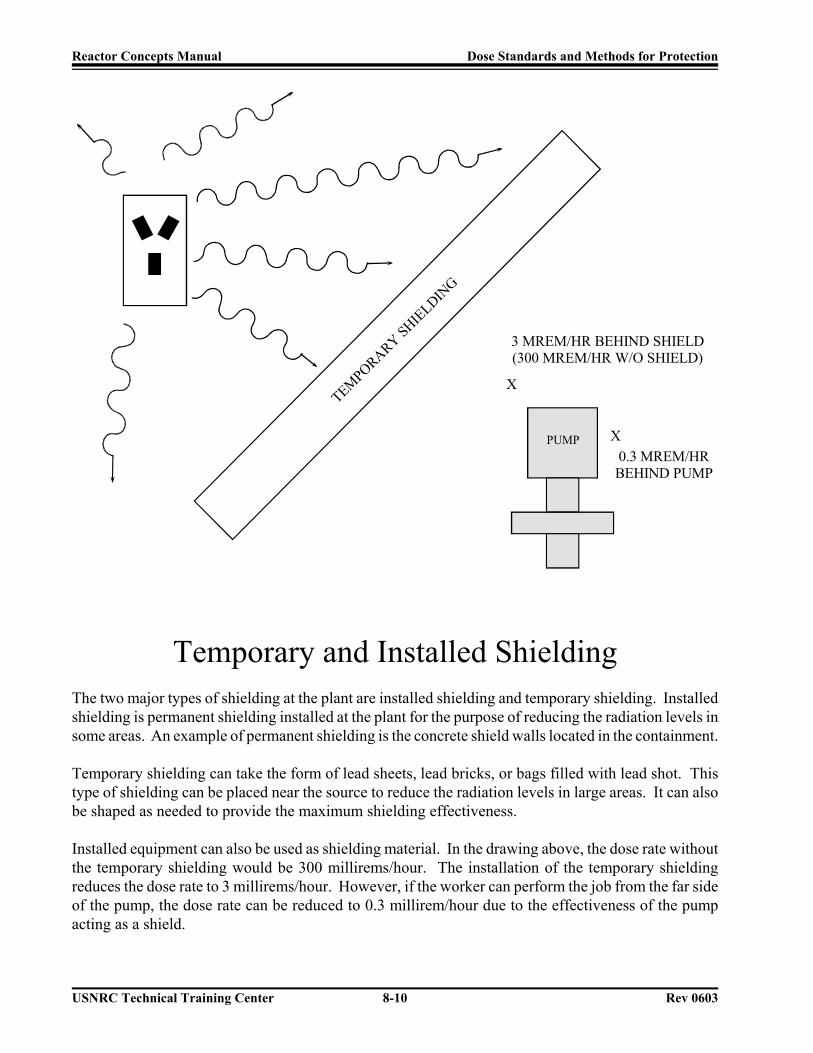
Reactor Concepts Manual Dose Standards and Methods for Protection
USNRC Technical Training Center 8-10 Rev 0603
X
3 MREM/HR BEHIND SHIELD(300 MREM/HR W/O SHIELD)
PUMP X0.3 MREM/HRBEHIND PUMP
TEMPORARY SHIELDIN
G
Temporary and Installed ShieldingThe two major types of shielding at the plant are installed shielding and temporary shielding. Installedshielding is permanent shielding installed at the plant for the purpose of reducing the radiation levels insome areas. An example of permanent shielding is the concrete shield walls located in the containment.
Temporary shielding can take the form of lead sheets, lead bricks, or bags filled with lead shot. Thistype of shielding can be placed near the source to reduce the radiation levels in large areas. It can alsobe shaped as needed to provide the maximum shielding effectiveness.
Installed equipment can also be used as shielding material. In the drawing above, the dose rate withoutthe temporary shielding would be 300 millirems/hour. The installation of the temporary shieldingreduces the dose rate to 3 millirems/hour. However, if the worker can perform the job from the far sideof the pump, the dose rate can be reduced to 0.3 millirem/hour due to the effectiveness of the pumpacting as a shield.

Reactor Concepts Manual Dose Standards and Methods for Protection
USNRC Technical Training Center 8-11 Rev 0603
Lead Iron Concrete Water
Relative Effectiveness of VariousShielding Materials
Materials differ in their ability to shield (absorb) radiation. The figure above shows the relativeeffectiveness of four common shield materials (lead, iron, concrete, and water) for gamma radiation.To have the same gamma radiation exposure level at the outside of each material, it takes about twiceas much iron as lead, about twice as much concrete as iron, and about three times as much water asconcrete.
A thumb rule that can be used is that it takes 2 inches of lead to reduce the dose rate by a factor of 10.Therefore, if a radiation detector measured the dose rate at a certain distance to be 100 millirems/hour,2 inches of lead would reduce the dose rate to 10 millirems/hour. This value is called a tenth-valuethickness of lead. To accomplish the same reduction using the other materials would require 4 inchesof iron/steel, 8 inches of concrete, or 24 inches of water. These values are only thumb rules. The exactamount of material required depends upon the energy of the radiation (gamma ray) that is being shieldedagainst.

Reactor Concepts Manual Dose Standards and Methods for Protection
USNRC Technical Training Center 8-12 Rev 0603
Internal Exposure Control
1 ALI = 2000 DAC-hr = 5 Rems
Intakes of radioactive material are controlled by the Annual Limit on Intake (ALI), expressed in unitsof microcuries. The ALI is the primary limit for internal exposure control, and in the absence of anyexternal radiation, a worker may intake one ALI in a year. One ALI equals 5 rems internal dose.
Concentrations of radioactive materials in air are limited by the Derived Air Concentrations (DACs),which are derived from the ALI. The DACs are derived assuming a worker breathes 1.2 cubic metersof air per hour for 2000 hours per year. Therefore:
DAC (microcuries / ml) = ALI (microcuries)2.4 X 10 ml9
If a worker breathes air containing radioactive material at a concentration of 1 DAC for one hour, thenthe worker has been exposed to 1 DAC-hr. Therefore:
1 ALI = 2000 DAC - hr = 5 rems
Since the operational limit of 5 rems applies to the sum of the internal and external exposures, if aworker has some external dose, the ALI must be modified or offset to account for the external dose. Forexample, assume the worker has 2 rems from external sources of radiation. Only 3 more rems areallowed from internal radiation before the worker reaches the occupational whole body limit. Expressedin DAC-hr, this would be:
35 X 2000 DAC - hr = 1200 DAC - hr

Reactor Concepts Manual Dose Standards and Methods for Protection
USNRC Technical Training Center 8-13 Rev 0603
Protection Against Contamination
Utilize containmentsMaintain access control
Conduct frequent surveysUtilize protective clothing
Wear respiratory protectionPractice good housekeepingConduct follow up bioassaysMinimize radioactive leakage
The protective measures listed above are used to prevent, detect, and/or contain radioactivecontamination. Since radioactive contamination can be inhaled and/or ingested, the above measures arealso considered to be methods of protection against internal doses.
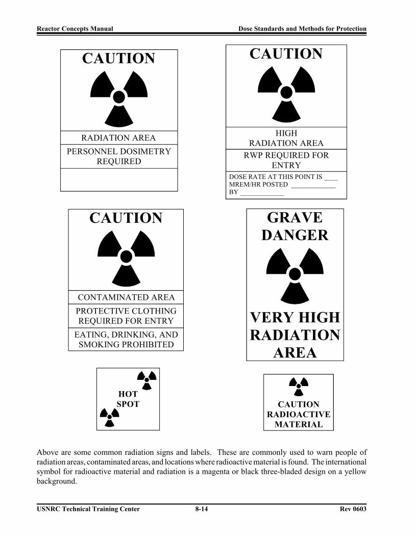
Reactor Concepts Manual Dose Standards and Methods for Protection
USNRC Technical Training Center 8-14 Rev 0603
CAUTIONCAUTION
RADIATION AREAPERSONNEL DOSIMETRY
REQUIRED
HIGHRADIATION AREA
RWP REQUIRED FORENTRY
DOSE RATE AT THIS POINT IS ____MREM/HR POSTED _____________BY _____________
CAUTION
CONTAMINATED AREA
EATING, DRINKING, ANDSMOKING PROHIBITED
PROTECTIVE CLOTHINGREQUIRED FOR ENTRY
HOTSPOT CAUTION
RADIOACTIVEMATERIAL
GRAVEDANGER
VERY HIGHRADIATION
AREA
Above are some common radiation signs and labels. These are commonly used to warn people ofradiation areas, contaminated areas, and locations where radioactive material is found. The internationalsymbol for radioactive material and radiation is a magenta or black three-bladed design on a yellowbackground.

Reactor Concepts Manual Biological Effects of Radiation
USNRC Technical Training Center 9-1 0603
BiologicalEffects ofRadiation
Whether the source of radiation isnatural or man-made, whether it is asmall dose of radiation or a large dose,there will be some biological effects.This chapter summarizes the short andlong term consequences which mayresult from exposure to radiation.

Reactor Concepts Manual Biological Effects of Radiation
USNRC Technical Training Center 9-2 0603
Radiation Causes Ionizations of:
ATOMS
which may affect
MOLECULES
which may affect
CELLS
which may affect
TISSUES
which may affect
ORGANS
which may affect
THE WHOLE BODY
Although we tend to think of biological effects in terms of the effect of radiation on living cells, inactuality, ionizing radiation, by definition, interacts only with atoms by a process called ionization.Thus, all biological damage effects begin with the consequence of radiation interactions with the atomsforming the cells. As a result, radiation effects on humans proceed from the lowest to the highest levelsas noted in the above list.

Reactor Concepts Manual Biological Effects of Radiation
USNRC Technical Training Center 9-3 0603
CELLULAR DAMAGE
Even though all subsequent biological effects can be traced back to the interaction of radiation withatoms, there are two mechanisms by which radiation ultimately affects cells. These two mechanismsare commonly called direct and indirect effects.

Reactor Concepts Manual Biological Effects of Radiation
USNRC Technical Training Center 9-4 0603
DamageTo DNA
FromIonization
Direct Effect
If radiation interacts with the atoms of the DNA molecule, or some other cellular component critical tothe survival of the cell, it is referred to as a direct effect. Such an interaction may affect the ability ofthe cell to reproduce and, thus, survive. If enough atoms are affected such that the chromosomes do notreplicate properly, or if there is significant alteration in the information carried by the DNA molecule,then the cell may be destroyed by “direct” interference with its life-sustaining system.

Reactor Concepts Manual Biological Effects of Radiation
USNRC Technical Training Center 9-5 0603
Indirect Effect
Radiolytic Decomposition of Water in a Cell
If a cell is exposed to radiation, the probability of the radiation interacting with the DNA molecule isvery small since these critical components make up such a small part of the cell. However, each cell,just as is the case for the human body, is mostly water. Therefore, there is a much higher probability ofradiation interacting with the water that makes up most of the cell’s volume.
When radiation interacts with water, it may break the bonds that hold the water molecule together,producing fragments such as hydrogen (H) and hydroxyls (OH). These fragments may recombine or mayinteract with other fragments or ions to form compounds, such as water, which would not harm the cell.However, they could combine to form toxic substances, such as hydrogen peroxide (H2O2), which cancontribute to the destruction of the cell.

Reactor Concepts Manual Biological Effects of Radiation
USNRC Technical Training Center 9-6 0603
Cellular Sensitivity to Radiation(from most sensitive to least sensitive)
Lymphocytes and Blood Forming Cells
Reproductive and Gastrointestinal (GI) Cells
Nerve and Muscle Cells
Not all living cells are equally sensitive to radiation. Those cells which are actively reproducing aremore sensitive than those which are not. This is because dividing cells require correct DNA informationin order for the cell’s offspring to survive. A direct interaction of radiation with an active cell couldresult in the death or mutation of the cell, whereas a direct interaction with the DNA of a dormant cellwould have less of an effect.
As a result, living cells can be classified according to their rate of reproduction, which also indicatestheir relative sensitivity to radiation. This means that different cell systems have different sensitivities.Lymphocytes (white blood cells) and cells which produce blood are constantly regenerating, and are,therefore, the most sensitive. Reproductive and gastrointestinal cells are not regenerating as quickly andare less sensitive. The nerve and muscle cells are the slowest to regenerate and are the least sensitivecells.

Reactor Concepts Manual Biological Effects of Radiation
USNRC Technical Training Center 9-7 0603
NORMAL REPAIR OF DAMAGE CELL DIES FROM DAMAGE
DAUGHTER CELLS DIE NO REPAIR OR NON-IDENTICALREPAIR BEFORE REPRODUCTION
Cells, like the human body, have a tremendous ability to repair damage. As a result, not all radiationeffects are irreversible. In many instances, the cells are able to completely repair any damage andfunction normally.
If the damage is severe enough, the affected cell dies. In some instances, the cell is damaged but is stillable to reproduce. The daughter cells, however, may be lacking in some critical life-sustainingcomponent, and they die.
The other possible result of radiation exposure is that the cell is affected in such a way that it does notdie but is simply mutated. The mutated cell reproduces and thus perpetuates the mutation. This couldbe the beginning of a malignant tumor.

Reactor Concepts Manual Biological Effects of Radiation
USNRC Technical Training Center 9-8 0603
Organ Sensitivity(from most sensitive to least sensitive)
Blood Forming Organs
Reproductive and Gastrointestinal Tract Organs
Skin
Muscle and Brain
The sensitivity of the various organs of the human body correlate with the relative sensitivity of the cellsfrom which they are composed. For example, since the blood forming cells were one of the mostsensitive cells due to their rapid regeneration rate, the blood forming organs are one of the most sensitiveorgans to radiation. Muscle and nerve cells were relatively insensitive to radiation, and therefore, so arethe muscles and the brain.

Reactor Concepts Manual Biological Effects of Radiation
USNRC Technical Training Center 9-9 0603
Sensitivity
Rate of Reproduction
Oxygen Supply
The rate of reproduction of the cells forming an organ system is not the only criterion determiningoverall sensitivity. The relative importance of the organ system to the well being of the body is alsoimportant.
One example of a very sensitive cell system is a malignant tumor. The outer layer of cells reproducesrapidly, and also has a good supply of blood and oxygen. Cells are most sensitive when they arereproducing, and the presence of oxygen increases sensitivity to radiation. Anoxic cells (cells withinsufficient oxygen) tend to be inactive, such as the cells located in the interior of a tumor.
As the tumor is exposed to radiation, the outer layer of rapidly dividing cells is destroyed, causing it to“shrink” in size. If the tumor is given a massive dose to destroy it completely, the patient might die aswell. Instead, the tumor is given a small dose each day, which gives the healthy tissue a chance torecover from any damage while gradually shrinking the highly sensitive tumor.
Another cell system that is composed of rapidly dividing cells with a good blood supply and lots ofoxygen is the developing embryo. Therefore, the sensitivity of the developing embryo to radiationexposure is similar to that of the tumor, however, the consequences are dramatically different.

Reactor Concepts Manual Biological Effects of Radiation
USNRC Technical Training Center 9-10 0603
Whole Body Sensitivity Factors
Total DoseType of Cell
Type of RadiationAge of Individual
Stage of Cell DivisionPart of Body Exposed
General State of HealthTissue Volume Exposed
Time Interval over which Dose is Received
Whole body sensitivity depends upon the most sensitive organs which, in turn, depend upon the mostsensitive cells. As noted previously, the most sensitive organs are the blood forming organs and thegastrointestinal system.
The biological effects on the whole body from exposure to radiation will depend upon several factors.Some of these are listed above. For example, a person, already susceptible to infection, who receivesa large dose of radiation may be affected by the radiation more than a healthy person.

Reactor Concepts Manual Biological Effects of Radiation
USNRC Technical Training Center 9-11 0603
Radiation EffectsHigh Doses (Acute)
Low Doses (Chronic)
Biological effects of radiation are typically divided into two categories. The first category consists ofexposure to high doses of radiation over short periods of time producing acute or short term effects. Thesecond category represents exposure to low doses of radiation over an extended period of time producingchronic or long term effects.
High doses tend to kill cells, while low doses tend to damage or change them. High doses can kill somany cells that tissues and organs are damaged. This in turn may cause a rapid whole body responseoften called the Acute Radiation Syndrome (ARS). High dose effects are discussed on pages 6-12 to 6-16.
Low doses spread out over long periods of time don’t cause an immediate problem to any body organ.The effects of low doses of radiation occur at the level of the cell, and the results may not be observedfor many years. Low dose effects are discussed on pages 6-17 to 6-23.

Reactor Concepts Manual Biological Effects of Radiation
USNRC Technical Training Center 9-12 0603
Occupation High Dose Exposures
ChernobylIrradiators
Inadvertent Criticalities
Non-Occupational High Dose Exposures
Chernobyl (firefighters)Nagasaki and Hiroshima
Therapy source in Goiania, Brazil
Although we tend to associate high doses of radiation with catastrophic events such as nuclear weaponsexplosions, there have been documented cases of individuals dying from exposure to high doses ofradiation resulting from workplace accidents and other tragic events.
Some examples of deaths which have occurred as a result of occupational (worker related) accidents are:
Inadvertent criticality (too much fissionable material in the right shape at the wrong time)Irradiator (accidental exposure to sterilization sources, which can be more than 10 million curies)Chernobyl (plant workers)
An example of a nonoccupational accident occurred in 1987 in Goiania, Brazil. An abandoned medicaltherapy source (cesium) was found and cut open by people who did not know what it was. This resultedin the deaths of several members of the public and the spread of radioactive contamination over a largearea.
A recent inadvertent criticality event occurred in a fuel processing plant in Japan.

Reactor Concepts Manual Biological Effects of Radiation
USNRC Technical Training Center 9-13 0603
High Dose Effects
Dose (Rad)
15 - 25
50
100
150
320 - 360
480 - 540
1,100
Effect Observed
Blood count changes in a group of people
Blood count changes in an individual
Vomiting (threshold)
Death (threshold)
LD 50/60 with minimal care
LD 50/60 with supportive medical care
LD 50/60 with intensive medical care (bone marrowtransplant)
Every acute exposure will not result in death. If a group of people is exposed to a whole bodypenetrating radiation dose, the above effects might be observed. The information for this table wasextracted from NCRP Report No. 98, Guidance on Radiation Received in Space Activities, 1989.
In the above table, the threshold values are the doses at which the effect is first observed in the mostsensitive of the individuals exposed. The LD 50/60 is the lethal dose at which 50% of those exposedto that dose will die within 60 days.
It is sometimes difficult to understand why some people die while others survive after being exposedto the same radiation dose. The main reasons are the health of the individuals at the time of the exposureand their ability to combat the incidental effects of radiation exposure, such as the increasedsusceptibility to infections.

Reactor Concepts Manual Biological Effects of Radiation
USNRC Technical Training Center 9-14 0603
Other High Dose Effects
Skin BurnsHair LossSterility
Cataracts
Besides death, there are several other possible effects of a high radiation dose.
Effects on the skin include erythema (reddening like sunburn), dry desquamation (peeling), and moistdesquamation (blistering). Skin effects are more likely to occur with exposure to low energy gamma,X-ray, or beta radiation. Most of the energy of the radiation is deposited in the skin surface. The doserequired for erythema to occur is relatively high, in excess of 300 rad. Blistering requires a dose inexcess of 1,200 rad.
Hair loss, also called epilation, is similar to skin effects and can occur after acute doses of about 500 rad.
Sterility can be temporary or permanent in males, depending upon the dose. In females, it is usuallypermanent, but it requires a higher dose. To produce permanent sterility, a dose in excess of 400 rad isrequired to the reproductive organs.
Cataracts (a clouding of the lens of the eye) appear to have a threshold of about 200 rad. Neutrons areespecially effective in producing cataracts, because the eye has a high water content, which is particularlyeffective in stopping neutrons.
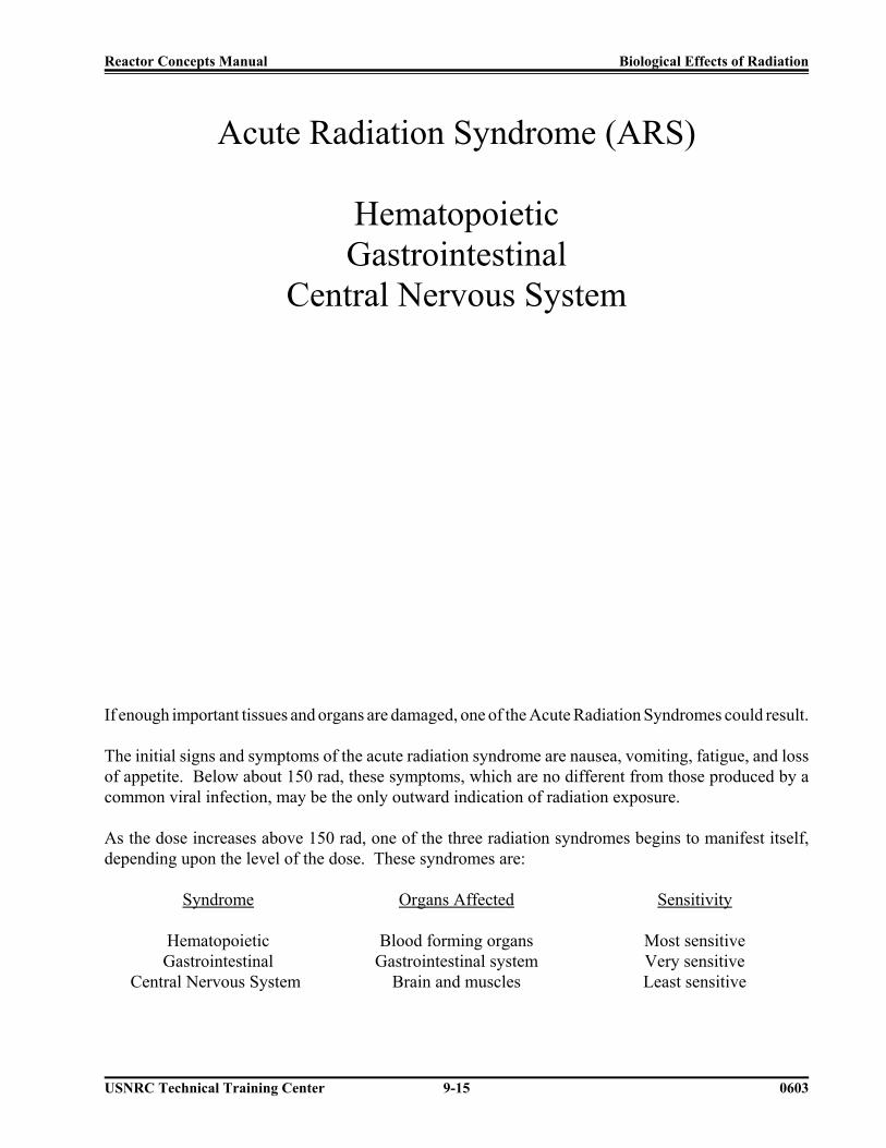
Reactor Concepts Manual Biological Effects of Radiation
USNRC Technical Training Center 9-15 0603
Acute Radiation Syndrome (ARS)
HematopoieticGastrointestinal
Central Nervous System
If enough important tissues and organs are damaged, one of the Acute Radiation Syndromes could result.
The initial signs and symptoms of the acute radiation syndrome are nausea, vomiting, fatigue, and lossof appetite. Below about 150 rad, these symptoms, which are no different from those produced by acommon viral infection, may be the only outward indication of radiation exposure.
As the dose increases above 150 rad, one of the three radiation syndromes begins to manifest itself,depending upon the level of the dose. These syndromes are:
Syndrome
HematopoieticGastrointestinal
Central Nervous System
Organs Affected
Blood forming organsGastrointestinal system
Brain and muscles
Sensitivity
Most sensitiveVery sensitiveLeast sensitive

Reactor Concepts Manual Biological Effects of Radiation
USNRC Technical Training Center 9-16 0603
Summary of Biological Response to High Doses of Radiation
< 5 rad
~ 5 rad to 50 rad
~ 50 rad to 150rad
~ 150 rad to1,100 rad
~ 1,100 rad to2,000 rad
> 2,000 rad
-
-
-
-
-
-
No immediate observable effects
Slight blood changes may be detected by medical evaluations
Slight blood changes will be noted and symptoms of nausea,fatigue, vomiting, etc. likely
Severe blood changes will be noted and symptoms appearimmediately. Approximately 2 weeks later, some of thoseexposed may die. At about 300 - 500 rad, up to one half of thepeople exposed will die within 60 days without intensive medicalattention. Death is due to the destruction of the blood formingorgans. Without white blood cells, infection is likely. At thelower end of the dose range, isolation, antibiotics, andtransfusions may provide the bone marrow time to generate newblood cells and full recovery is possible. At the upper end of thedose range, a bone marrow transplant may be required to producenew blood cells.
The probability of death increases to 100% within one to twoweeks. The initial symptoms appear immediately. A few dayslater, things get very bad, very quickly since the gastrointestinalsystem is destroyed. Once the GI system ceases to function,nothing can be done, and medical care is for comfort only.
Death is a certainty. At doses above 5,000 rad, the centralnervous system (brain and muscles) can no longer control thebody functions, including breathing blood circulation.Everything happens very quickly. Nothing can be done, andmedical care is for comfort only.
As noted, there is nothing that can be done if the dose is high enough to destroy the gastrointestinal orcentral nervous system. That is why bone marrow transplants don’t always work.
In summary, radiation can affect cells. High doses of radiation affect many cells, which can result intissue/organ damage, which ultimately yields one of the Acute Radiation Syndromes. Even normallyradio-resistant cells, such as those in the brain, cannot withstand the cell killing capability of very highradiation doses. The next few pages will discuss the biological effects of low doses of radiation.
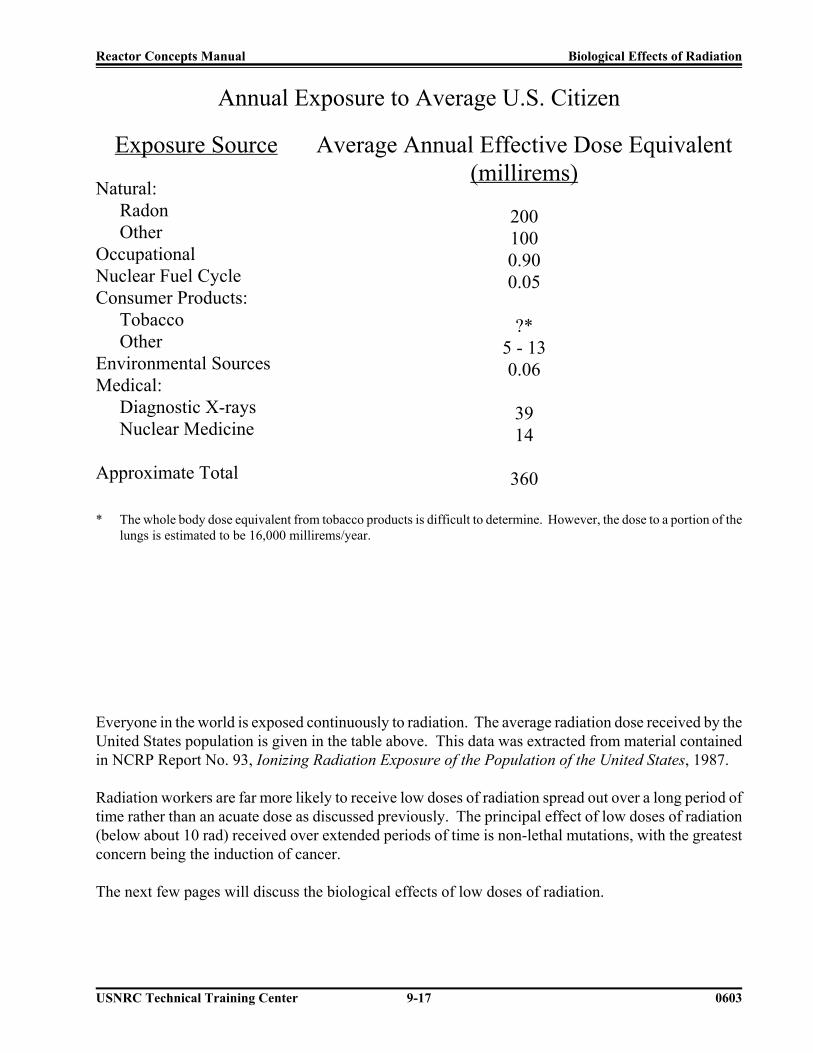
Reactor Concepts Manual Biological Effects of Radiation
USNRC Technical Training Center 9-17 0603
Annual Exposure to Average U.S. Citizen
Exposure Source
Natural:RadonOther
OccupationalNuclear Fuel CycleConsumer Products:
TobaccoOther
Environmental SourcesMedical:
Diagnostic X-raysNuclear Medicine
Approximate Total
Average Annual Effective Dose Equivalent(millirems)
2001000.900.05
?*5 - 130.06
3914
360
* The whole body dose equivalent from tobacco products is difficult to determine. However, the dose to a portion of thelungs is estimated to be 16,000 millirems/year.
Everyone in the world is exposed continuously to radiation. The average radiation dose received by theUnited States population is given in the table above. This data was extracted from material containedin NCRP Report No. 93, Ionizing Radiation Exposure of the Population of the United States, 1987.
Radiation workers are far more likely to receive low doses of radiation spread out over a long period oftime rather than an acuate dose as discussed previously. The principal effect of low doses of radiation(below about 10 rad) received over extended periods of time is non-lethal mutations, with the greatestconcern being the induction of cancer.
The next few pages will discuss the biological effects of low doses of radiation.

Reactor Concepts Manual Biological Effects of Radiation
USNRC Technical Training Center 9-18 0603
Categories of Effects of Exposure toLow Doses of Radiation
GeneticSomaticIn-Utero
There are three general categories of effects resulting from exposure to low doses of radiation. Theseare:
Genetic - The effect is suffered by the offspring of the individual exposed.
Somatic - The effect is primarily suffered by the individual exposed. Since cancer is theprimary result, it is sometimes called the Carcinogenic Effect.
In-Utero - Some mistakenly consider this to be a genetic consequence of radiation exposure,because the effect, suffered by a developing embryo/fetus, is seen after birth.However, this is actually a special case of the somatic effect, since the embryo/fetusis the one exposed to the radiation.

Reactor Concepts Manual Biological Effects of Radiation
USNRC Technical Training Center 9-19 0603
Genetic Effects
Mutation of the reproductive cells passed on tothe offspring of the exposed individual
The Genetic Effect involves the mutation of very specific cells, namely the sperm or egg cells.Mutations of these reproductive cells are passed to the offspring of the individual exposed.
Radiation is an example of a physical mutagenic agent. There are also many chemical agents as wellas biological agents (such as viruses) that cause mutations.
One very important fact to remember is that radiation increases the spontaneous mutation rate, but doesnot produce any new mutations. Therefore, despite all of the hideous creatures supposedly produced byradiation in the science fiction literature and cinema, no such transformations have been observed inhumans. One possible reason why genetic effects from low dose exposures have not been observed inhuman studies is that mutations in the reproductive cells may produce such significant changes in thefertilized egg that the result is a nonviable organism which is spontaneously resorbed or aborted duringthe earliest stages of fertilization.
Although not all mutations would be lethal or even harmful, it is prudent to assume that all mutationsare bad, and thus, by USNRC regulation (10 CFR Part 20), radiation exposure SHALL be held to theabsolute minimum or As Low As Reasonably Achievable (ALARA). This is particularly important sinceit is believed that risk is directly proportional to dose, without any threshold.

Reactor Concepts Manual Biological Effects of Radiation
USNRC Technical Training Center 9-20 0603
Somatic Effects
Effect is suffered by the individual exposedPrimary consequence is cancer
Somatic effects (carcinogenic) are, from an occupational risk perspective, the most significant since theindividual exposed (usually the radiation worker) suffers the consequences (typically cancer). As notedin the USNRC Regulatory Guide 8.29, this is also the NRC’s greatest concern.
Radiation is an example of a physical carcinogenic, while cigarettes are an example of a chemical cancercausing agent. Viruses are examples of biological carcinogenic agents.
Unlike genetic effects of radiation, radiation induced cancer is well documented. Many studies havebeen completed which directly link the induction of cancer and exposure to radiation. Some of thepopulation studied and their associated cancers are:
Lung cancer - uranium minersBone cancer - radium dial paintersThyroid cancer - therapy patientsBreast cancer - therapy patientsSkin cancer - radiologistsLeukemia - bomb survivors, in-utero exposures, radiologists, therapy patients

Reactor Concepts Manual Biological Effects of Radiation
USNRC Technical Training Center 9-21 0603
In-Utero Effects
Effects of radiation on embryo/fetus
Intrauterine DeathGrowth Retardation
Developmental AbnormalitiesChildhood Cancers
The in-utero effect involves the production of malformations in developing embryos.
Radiation is a physical teratogenic agent. There are many chemical agents (such as thalidomide) andmany biological agents (such as the viruses which cause German measles) that can also producemalformations while the baby is still in the embryonic or fetal stage of development.
The effects from in-utero exposure can be considered a subset of the general category of somatic effects.The malformation produced do not indicate a genetic effect since it is the embryo that is exposed, notthe reproductive cells of the parents.
The actual effects of exposure in-utero that will be observed will depend upon the stage of fetaldevelopment at the time of the exposure:
Weeks Post Conception
0 - 1 (preimplantation)2 - 7 (organogenesis)
8 - 40 (fetal stage)
Effect
Intrauterine deathDevelopmental abnormalities/growth retardation/cancerSame as above with lower risk plus possible functional abnormalities

Reactor Concepts Manual Biological Effects of Radiation
USNRC Technical Training Center 9-22 0603
Radiation Risk:
With any exposure to radiation, there is some risk
The approximate risks for the three principal effects of exposure to low levels of radiation are:
Effect
GeneticSomatic (cancer)In-Utero (cancer)
In-Utero (all effects)
Excess Cases per 10,000 exposed per rad
2 to 44 to 204 to 12
20 to 200
Genetic - Risks from 1 rem of radiation exposure to the reproductive organs are approximately 50to 1,000 times less than the spontaneous risk for various anomalies.
Somatic - For radiation induced cancers, the risk estimate is small compared to the normalincidence of about 1 in 4 chances of developing any type of cancer. However, not allcancers are associated with exposure to radiation. The risk of dying from radiationinduced cancer is about one half the risk of getting the cancer.
In-Utero - Spontaneous risks of fetal abnormalities are about 5 to 30 times greater than the risk ofexposure to 1 rem of radiation. However, the risk of childhood cancer from exposure in-utero is about the same as the risk to adults exposed to radiation. By far, medical practiceis the largest source of in-utero radiation exposure.
Because of overall in-utero sensitivity, the NRC, in 10 CFR Part 20, requires that for the declaredpregnant woman, the radiation dose to the embryo/fetus be maintained less than or equal to 0.5 remduring the entire gestation period. This limit is one-tenth of the annual dose permitted to adult radiationworkers. This limit applies to the worker who has voluntarily declared her pregnancy in writing. Forthe undeclared pregnant woman, the normal occupational limits for the adult worker apply (as well asALARA).

Reactor Concepts Manual Biological Effects of Radiation
USNRC Technical Training Center 9-23 0603
RISK
DOSE0
Linear No-Threshold Risk Model
General consensus among experts is that some radiation risks are related to radiation dose by a linear,no-threshold model. This model is accepted by the NRC since it appears to be the most conservative.
LINEAR - An increase in dose results in a proportional increase in riskNO-THRESHOLD - Any dose, no matter how small, produces some risk
The risk does not start at 0 because there is some risk of cancer, even with no occupational exposure.The slope of the line just means that a person that receives 5 rems in a year incurs 10 times as much riskas a person that receives 0.5 rems in a year.
Exposure to radiation is not a guarantee of harm. However, because of the liner, no-threshold model,more exposure means more risk, and there is no dose of radiation so small that it will not have someeffect.

Reactor Concepts Manual Radioactive Waste Management
USNRC Technical Training Center 10-1 0703
RadioactiveWaste
Management
This section will discuss the sources, handling, and ultimate disposal of radioactive wastes (sometimesreferred to as radwaste) generated by nuclear power plant operation.

Reactor Concepts Manual Radioactive Waste Management
USNRC Technical Training Center 10-2 0703
Solid, liquid, and gaseous materialsfrom nuclear operations
that are radioactive or become radioactive(contaminated) and for which there is
no further use
Radioactive waste is material that is radioactive that is no longer needed at the plant and can be disposedof. The following are some examples of the sources of radioactive waste.
After a fuel assembly has been used in the reactor core to generate power, there is a largeinventory of fission products held inside the cladding of the fuel. Since the processing of spentfuel is not done for commercial power plants, the fuel must be disposed of in some safe fashion.
The activation products that are carried by the reactor coolant system are collected by the filtersand demineralizers in the cleanup systems. When the filters and demineralizer resins are full,they must be disposed of as radioactive waste.
A paper towel or rag used to wipe up radioactive water must be disposed of as radioactivewaste.
A contaminated piece of equipment that is no longer useable must be disposed of as radioactivewaste.

Reactor Concepts Manual Radioactive Waste Management
USNRC Technical Training Center 10-3 0703
High Level Radioactive Waste
Low Level Radioactive Waste
There are two general classifications of radioactive waste. These are:
High Level Radioactive Wasteand
Low Level Radioactive Waste
Disposal of high level radioactive waste is the responsibility of the Department of Energy. The licensingof high level waste disposal facilities is the responsibility of the USNRC, as specified in 10 CFR Part60, “Disposal of High-Level Radioactive Waste in Geologic Repositories.”
Disposal of low level radioactive waste is also subject to licensing by the USNRC. The regulations forthese disposal facilities are in 10 CFR Part 61, “Licensing Requirements for Land Disposal ofRadioactive Waste.”

Reactor Concepts Manual Radioactive Waste Management
USNRC Technical Training Center 10-4 0703
FUEL HANDLINGBRIDGE
SPENTFUELPOOL
FUEL STORAGERACKS
Spent fuel is classified as high level radioactive waste. This is due to the buildup of very highlyradioactive fission products as the fuel is used in the reactor.
When the spent fuel is removed from the reactor to be replaced with new fuel, it must be stored for aperiod of time in the spent fuel pool. The spent fuel must be kept under water due to the heat beinggenerated by the decay of the fission products and to limit the radiation levels in the area of the spentfuel pool. The spent fuel pools are usually located onsite. However, due to the amount of fuel somepower plants must store, there are some offsite storage pools.
Presently, there are no disposal facilities for commercial high level radioactive waste.

Reactor Concepts Manual Radioactive Waste Management
USNRC Technical Training Center 10-5 0703
Air inlet
Dry shieldedcanister
HSM wall
HSM roofAir exitHSM door
Grapple
End cap
Support ringSpacer disk
Siphon tube
Guide sleeve
Support rod
Canister body
Lead
After several years, the heat generated by the decay of the fission products decreases sufficiently to allowthe storage of the spent fuel in an air-cooled, dry, above ground storage facility. These facilities mustbe designed to remove the heat from the spent fuel and be designed to limit the radiation in the areasaround the facilities.
The illustration above is a horizontal storage module (HSM) with shielded canister. The fuel would beinside the canister, which would then be placed inside the HSM. This is just one of several designs ofdry fuel storage, some horizontal and some vertical.

Reactor Concepts Manual Radioactive Waste Management
USNRC Technical Training Center 10-6 0703
Low Level Radioactive Waste:
Liquid:Equipment leakoff points
Equipment vents and drainsFloor drain system
Solid:Contaminated rags, tools, clothing, etc.
Spent filter cartridgesSpent demineralizer resins
Gaseous:Equipment vents
Liquid waste system (evaporator gas stripper)
All radioactive waste that is not high level radioactive waste is low level radioactive waste. Theprincipal sources of low level radwaste are the reactor coolant (water) and the components andequipment that come in contact with the coolant. The major constituents of low level radwaste areactivation products (crud) and a very small percentage of fission products (if any leak out of the fuelrods).
Low level radioactive wastes can be in the form of solids, liquids, or gases. The list above gives someexamples of the sources of each form of low level radwaste.
Low level radioactive waste is also classified based upon the concentration and type of radionuclidesinvolved (10 CFR Part 61).
Class A waste is usually segregated from other waste at the disposal site. It must meet the minimumrequirements. In addition to minimum requirements, Class B waste must meet more rigorousrequirements on waste form to ensure stability after disposal. Class C waste must meet all of the ClassB requirements and requires additional measures at the disposal facility to protect against inadvertentintrusion.

Reactor Concepts Manual Radioactive Waste Management
USNRC Technical Training Center 10-7 0703
NON-REGENERATIVEHEAT EXCHANGER
REACTOR COOLANTSYSTEM
CONTAINMENT
CORE
RCP SEALINJECTION
LETDOWN FILTER
COOLING WATER
PUREWATERTANKVOLUME
CONTROLTANK
PURE WATERTRANSFER PUMP
BORIC ACIDTRANSFER PUMP
CHEMICALADDITION
TANK
F
DEMINERALIZERTANKS
REGENERATIVEHEAT EXCHANGER
S/G
PZR
RCP
CONTAINMENT SUMP
CHARGINGPUMP
BORICACIDTANK
SOLIDRADIOACTIVE
WASTE
LIQUIDRADIOACTIVE
WASTE
WASTE GASTO WASTE
GAS DECAY TANK
The chemical and volume control system (CVCS) on a pressurized water reactor is used to remove theactivation products and fission products from the reactor coolant. It will be used to show some of thesources of solid, liquid, and gaseous radioactive wastes.
As the reactor coolant flows through the chemical and volume control system, it passes throughdemineralizers and filters. The demineralizer resins and filter cartridges become contaminated due tothe impurities they remove from the coolant. After use, the resins and cartridges will be disposed of assolid radioactive waste. In the volume control tank, the reactor coolant is sprayed into a hydrogen gasbubble. As the water is sprayed, gases are stripped out of solution. These gases can then be vented tothe waste gas system to be processed as gaseous radioactive waste. If water needs to be removed fromthe reactor coolant system, there is a flow path that can be lined up to divert the reactor coolant flowfrom the chemical and volume control system to the liquid radwaste system for processing.
The chemical and volume control system is only one example of how radioactive waste is generated bythe operation of a power plant system. Wastes are also generated due to the cleanup of areas (rags,clothing, etc.), the replacement of equipment (used parts, contaminated tools, etc.), and by improperhousekeeping (contaminated clothing from stepping in a puddle, etc.).

Reactor Concepts Manual Radioactive Waste Management
USNRC Technical Training Center 10-8 0703
Low Level Radwaste Handling
Because of the different characteristics of solids, liquids, and gases, each must be processed differently.The waste must also be processed in such a manner as to minimize the risk of exposure to the public.The block diagram on page 10-9 shows the layout of a simple radwaste handling system. A discussionof the dose a member of the public can receive from releases from the plant can be found on page 10-11.
Liquids are processed to remove the radioactive impurities. These processes might include:
• Filtering,• Routing through demineralizers,• Boiling off the water (evaporation) and leaving the solid impurities (which are then processed
as solid radioactive waste), and/or• Storing the liquid for a time period to allow the radioactive material to decay.
After processing, the water will be sampled. If samples show the water meets the required standards,the water can be placed in the storage tanks for use in the plant or be released to the environment. If thesamples show the water does not meet the standards, it will be reprocessed.
Some materials, such as the evaporator bottoms (solids that remain after the water is evaporated off),will be mixed with some material to form a solid (such as concrete). This is also sometimes done withspent demineralizer resins. After mixing with a hardener, the material is processed as solid radioactivewaste.
Gaseous wastes are filtered, compressed to take up less space, and then allowed to decay for some timeperiod. After the required time has passed, the gases will be sampled. If the required limits are met, thegases will be released to the atmosphere, or sometimes the gases will be reused in specific areas of theplant.
Solid wastes are packaged as required and shipped to a burial site for disposal (transportation ofradioactive material is discussed in Chapter 11).

Reactor C
oncepts Manual
Radioactive W
aste Managem
ent
USN
RC
Technical T
raining Center
10-90703
LiquidRadwaste Filter Ion
Exchanger
Storage(Decay)
andSampleTank
Dilutionand
Discharge
Low Solids
Evaporator
High Solids
Spent Resins
SolidificationProcess
De-Water
Bottoms
Rags, tools, clothes, filter cartridges, etc.
Dilutionand
DischargeFilter
Storage(Decay)
andSampleTank
FilterGaseousRadwaste
SolidRadwaste
Compressor
Off-site
(Burial)Drum
Gases
Radioactive W
aste Handling System

Reactor Concepts Manual Radioactive Waste Management
USNRC Technical Training Center 10-10 0703
GASEOUS EFFLUENT
NUCLEAR POWER PLANT
FUEL TRANSPORT
LIQUIDEFFLUENTA
ir Submersion
Irrigation
Irrigation
DirectIrradiation
GMC
2%
Exposure toDepositedMaterials
Ingestion
Shoreline Exposure
Crop D
epos it ion/Upt ake
Dispositio n to Grou nd
Inhalation and Skin Absorption
Upt
ake b
y A
quat
ic Fo
ods
Gaseous and liquid radioactive wastes, after processing, may be released to the environment. This canresult in the exposure of members of the public. The diagram above shows some of the pathways thatcould result in the exposure of a member of the public.
Liquid releases could be taken in by the aquatic growth, which could then be consumed by an individual.The water could be used to irrigate crops, or processed as drinking water. Also, the individual couldreceive direct exposure from the release if in the vicinity of the water, such as swimming or sunbathing.
Gaseous releases could result in exposures by being inhaled by the individual. Also, if the individualis in the vicinity of the release, a direct exposure could be the result.
The transport of solid radwaste and fuel also contribute to the exposure of the average individual.
The amount of exposure received due to all of these processes is very small, when compared to theaverage yearly dose received (see Chapter 8). Also, there are limits placed on the amount of exposurea member of the public can receive from a nuclear power plant.

Reactor Concepts Manual Radioactive Waste Management
USNRC Technical Training Center 10-11 0703
10 CFR Part 20 Dose Standards
2 millirems in any one hour from external sources in anunrestricted area
100 millirems in a calendar year(sum of external and internal radiation)
in a controlled or unrestricted area
10 CFR Part 50 Design Objectives
Liquids3 millirems/year to the whole body
10 millirems/year to any organ
Gases5 millirems/year to the whole body
15 millirems/year to the skin
Solids and Iodine15 millirems/year to any organ
As discussed in Chapter 9, 10 CFR Part 20 states that the licensee must control radioactive material suchthat no member of the public in an unrestricted area receives a dose of 2 millirems in any one hour fromexternal sources or 100 millirems in a calendar year from external and internal sources in a controlledor unrestricted area. This control of radioactive material would also include the release of radioactivematerial to the environment, air, or water.
In addition to the limits of 10 CFR Part 20, the NRC has issued numerical design objectives for eachreactor unit for exposure from radioactive material releases into water and air. These design objectivesare published in 10 CFR Part 50 and are considerably lower than the limits published in 10 CFR Part20.

Reactor Concepts Manual Radioactive Waste Management
USNRC Technical Training Center 10-12 0703
Regional Low-Level Waste Compacts
NorthwestAlaskaHawaiiIdaho
MontanaOregon
UtahWyoming
Washington
SouthwesternArizona
North DakotaSouth Dakota
California
Rocky MountainColoradoNevada
New Mexico
MidwestIndiana
IowaMinnesotaMissouri
OhioWisconsin
CentralArkansasKansas
LouisianaOklahomaNebraska
Central MidwestKentucky
Illinois
AppalachianDelawareMaryland
West VirginiaPennsylvania
AtlanticConnecticutNew Jersey
South Carolina
SoutheastAlabamaFloridaGeorgia
MississippiTennesseeVirginia
TexasMaine
VermontTexas
UnaffiliatedDistrict of Columbia
MassachusettsMichigan
New HampshireNew York
North CarolinaPuerto Rico
Rhode IslandU. S. Army
In addition to proper handling, the proper disposal of radioactive waste will help to minimize the dosereceived by members of the public. Currently, low level radioactive waste is all that is accepted fordisposal at burial sites. There are three disposal sites which are presently operating. Barnwell, SouthCarolina can accept all low-level waste. Hanford, Washington can accept waste from the Northwest andRocky Mountain compacts. Clive, Utah is only authorized to accept Class A, low-activity, high-volumewaste.
The Nuclear Waste Policy Act of 1980 gives States the responsibilities for management and disposal ofmost civilian low-level radwaste. Disposal is regulated by a State entering into an agreement with theNRC (Agreement State).
The Act also divided the US into regional low level waste compacts. Each compact has a host Statewhich will contain the low-level waste disposal site. Some compacts have more than one host State.Some disposal sites are being reviewed at this time.

Reactor Concepts Manual Radioactive Waste Management
USNRC Technical Training Center 10-13 0703
Even though there is not presently a high-level waste repository accepting spent fuel for disposal, theNuclear Waste Policy Act of 1982, as amended, directed the Department of Energy to site, design,construct, and operate a high-level waste repository.

Reactor Concepts Manual Radioactive Waste Management
USNRC Technical Training Center 10-14 0703
YUCCA MOUNTAIN
AND
REGULATIONS
The proposed site for the high level waste geologic repository is Yucca Mountain, Nevada. The site willresemble a mining complex. On the surface will be the waste handling facilities (offices, repair shops,etc.). About 1000 feet below the surface will be the disposal site for the containerized waste.
The EPA has published its final regulations for the site. They can be found in 40 CFR Part 197,“Environmental Radiation Protection Standards for Yucca Mountain, Nevada.” The regulations limitthe dose to the public to 15 mrem/year from the facility. The regulations also impose an additionalgroundwater protection dose limit of 4 mrem/year from beta and photon emitting radionuclides.
The NRC final regulation (10 CFR Part 63, “Disposal of High-Level Radioactive Wastes in a GeologicRepository at Yucca Mountain, Nevada”) conforms to the EPA regulations.
Previously, it was mentioned that 10 CFR Part 60 dealt with the disposal of high level wastes. Thisregulation will continue to apply to all other high level facilities except for Yucca Mountain. As for 10CFR Part 63, it will only apply to a geologic repository at Yucca Mountain.

Reactor Concepts Manual Radioactive Waste Management
USNRC Technical Training Center 10-15 0703
Cask Dimensions
Height: 22 ftDiameter: 12 ftWeight: 200 tons
(empty)
220 tons(loaded)
Sealed StorageCask
The container would be a large storage cask that would hold the high-level radioactive waste.

Reactor Concepts Manual Transportation of Radioactive Material
USNRC Technical Training Center 11-1 Rev 0703
Santa Fe
Haza rdo us
Transportationof
RadioactiveMaterial
The issues associated with the transportation of radioactive material are very complex due in part to theregulatory requirements of both the NRC and the Department of Transportation (DOT). As a result, this will bea very brief overview of the relevant issues.

Reactor Concepts Manual Transportation of Radioactive Material
USNRC Technical Training Center 11-2 Rev 0703
UN Classification
Class 1 ExplosivesClass 2 GasesClass 3 Flammable LiquidsClass 4 Flammable SolidsClass 5 Oxidizers and Organic PeroxidesClass 6 Poisonous and Etiological MaterialsClass 7 Radioactive MaterialsClass 8 CorrosivesClass 9 Miscellaneous Hazardous Materials
All hazardous materials which could potentially be transported are assigned to one of the nine UnitedNations Classes. In general, the hazardous materials listed pose an immediate threat to health and safety.However, for radioactive material, the threat is potentially the non-immediate risk of cancer, althoughin large enough quantities, radiation can pose an immediate threat.

Reactor Concepts Manual Transportation of Radioactive Material
USNRC Technical Training Center 11-3 Rev 0703
Groups Promulgating Rules GoverningTransport of Radioactive Materials
Department of TransportationNuclear Regulatory Commission
Department of EnergyPostal ServicesState Agencies
Regulations to control the transport of radioactive materials were initiated about 1935 by the PostalService. Over the years, the Interstate Commerce Commission (ICC) became involved. Currently, thereare at least five groups which promulgate rules governing the transport of radioactive material. Theseare the DOT, NRC, Postal Service, DOE, and the States.
Of these agencies, the DOT and NRC are the primary ones issuing regulations based upon the standardsdeveloped by the International Atomic Energy Agency (IAEA).

Reactor Concepts Manual Transportation of Radioactive Material
USNRC Technical Training Center 11-4 Rev 0703
UNITEDSTAT ESNU
CLEAR
R EGU LATORYCOMMISSION
UNITED
STATES OFAM
ERICA
NOI
TATR
OPSNARTFOTNE
MTRAPED
The NRC and DOT share responsibility for the control of radioactive material transport based upon aMemorandum of Understanding (MOU).
In general, DOT regulations (49 CFR) are more detailed. They cover all aspects of transportation,including packaging, shipper and carrier responsibilities, documentation, and all levels of radioactivematerial from exempt quantities to very high levels.
The NRC regulations (10 CFR 71) are primarily concerned with special packaging requirements forhigher level quantities. NRC regulation 10 CFR 71.5 requires NRC licensees transporting radioactivematerial to comply with DOT regulations when NRC regulations do not apply.

Reactor Concepts Manual Transportation of Radioactive Material
USNRC Technical Training Center 11-5 Rev 0703
For transportation purposes, radioactive material is defined as any material which has a specific activitygreater than 0.002 microcuries per gram. This definition does not specify a quantity, only aconcentration. As an example, pure cobalt-60 has a specific activity of 1,000 curies per gram, which isabout 500 billion times greater than the definition. However, uranium-238 has a specific activity of only0.3 microcuries per gram, which is only 150 times greater than the definition.
Although both exceed the definition of radioactive material in their pure form, either of these materialscould be uniformly mixed with enough substance, such as dirt, which would cause the concentration tofall below the definition. In the case of uranium-238, if one gram were mixed with about 150 grams ofdirt (about 1/3 of a pound), the concentration could be classified as non-radioactive.
Remember, however, that the definition of radioactive material above only applies for transportation.

Reactor Concepts Manual Transportation of Radioactive Material
USNRC Technical Training Center 11-6 Rev 0703
Since transport accidents cannot be prevented, the regulations are primarily designed to:
• Insure safety in routine handling situations for minimally hazardous material and• Insure integrity under all circumstances for highly dangerous materials.
These goals are accomplished by focusing on the package and its ability to:
• Contain the material (prevent leaks),• Prevent unusual occurrences (such as criticality), and• Reduce external radiation to safe levels (provide shielding).

Reactor Concepts Manual Transportation of Radioactive Material
USNRC Technical Training Center 11-7 Rev 0703
Packages
Strong Tight ContainerType A PackagesType B Packages
The three basic types of packages are strong tight containers, whose characteristics are not specified byregulation, followed by Type A containers, and finally Type B containers, both of which have veryspecific requirements in the regulations.
A strong tight container is designed to survive normal transportation handling. In essence, if the materialmakes it from point X to point Y without being released, the package was a strong tight container.
A Type A container, on the other hand, is designed to survive normal transportation handling and minoraccidents.
Type B containers must be able to survive severe accidents.
Fissile materials, which could be involved in a criticality accident, also have additional requirements.

Reactor Concepts Manual Transportation of Radioactive Material
USNRC Technical Training Center 11-8 Rev 0703
FIBERBOARD BOX WOODEN BOX STEEL DRUM
Type A
Type A packaging is based on performance requirements which means it must withstand or survivecertain tests. The shape of the package or material from which it is constructed is irrelevant. A TypeA package may be a cardboard box, a wooden crate, or a metal drum. The shipper must havedocumentation which shows that the specific design being used has passed the required tests.

Reactor Concepts Manual Transportation of Radioactive Material
USNRC Technical Training Center 11-9 Rev 0703
STEEL OUTER DRUMSHIELDED INNER CONTAINER
THERMAL INSULATIONBETWEEN CONTAINERS
INNERCONTAINMENTVESSEL
Type B
A Type B package may be a metal drum or a huge, massive shielded transport container. Like Type Apackages, Type B packages must pass certain tests. However, the Type B tests are considerably morerigorous than those required for Type A packages. Most Type B packages have been issued a Certificateof Compliance by the NRC.

Reactor Concepts Manual Transportation of Radioactive Material
USNRC Technical Training Center 11-10 Rev 0703
High IntegrityEncapsulationas a Sealed Source
MassiveSolid Metal
Stainless SteelOuter Capsule
High Integrity Welds
Tantalum InnerCapsule
Radioisotope
High Integrity Welds
Liquid in Bottle WithinMetal Container
Gas in Cylinder
Waste Material inPlastic Bag
Powder in GlassorPlastic Bottle
SpecialForm
NormalForm
The system created to ensure safe transport of radioactive materials is based on the assignment of anumber to each radionuclide, depending upon its form (i.e., its relative hazard if released from thepackage during transport). The number, or “A” value, represents the limit, in curies, permitted to betransported in a Type A package. There are two distinct categories established for this system.
Special form (A1) radionuclides are usually encapsulated sources which would only pose an externalradiation hazard, not a contamination hazard, if the package was ruptured.
Normal form (A2) radionuclides are usually not securely encapsulated and could yield significantcontamination if the package was ruptured. These materials could pose an internal hazard to people atthe scene of an accident. Normal form materials are typically liquids and powders.
Since the “A” values provide the limit for the amount in a package, A2 values cannot be greater than A1values, since A2 values represent material in normal form, which makes it more “hazardous.” However,for some nuclides, the hazard may be the same in either form so that A1 can be equal to A2. In any case,neither A1 nor A2 can be greater than 1000 curies.

Reactor Concepts Manual Transportation of Radioactive Material
USNRC Technical Training Center 11-11 Rev 0703
Sample “A” Values (curies)
MaterialSpecial Form
A1 ValuesNormal Form
A2 ValuesRatioA1/A2
Plutonium-239Strontium-90
Cobalt-60
2107
0.0020.47
1,000251
When A1 equals A2, the hazard is considered the same, whether the material is in normal or special form.This tends to be the case for gamma emitters. For alpha emitters, the normal form (unencapsulated) isconsidered to be 1,000 times more hazardous as the special form (sealed), so that the A1 values are about1,000 times lower. Beta emitters fall between the two.

Reactor Concepts Manual Transportation of Radioactive Material
USNRC Technical Training Center 11-12 Rev 0703
Quantity of Radioactive Materialwill determineClassification
Non-RadioactiveLimitedType AType B
Highway Route ControlledThe manner in which radioactive material is handled for transport depends upon the amount of materialand its relative hazard:
Non-Radioactive - If the amount of material is less than 0.002 microcuries per gram, it is notconsidered radioactive for transportation purposes
Limited Quantity - If the amount is greater than 0.002 microcuries per gram but does not exceedone thousandth of the A1 or A2 value (depending on the form), then thematerial is considered a limited quantity and needs only a strong tightcontainer, which should survive routine handling.
Type A Quantity - If the amount is less than or equal to the A1 or A2 value (depending on theform) but greater than one thousandth of the value, then the material requiresa Type A package, which should survive minor accidents.
Type B Quantity - If the amount is greater than the A1 or A2 value (depending on the form) butless than or equal to 3000 times these values, then the material requires aType B package, which should survive a serious accident.
Highway Route - If the amount is greater than 3000 times the A1 or A2 value (depending onControlled the form) but less than 27,000 curies, then the material is a highway routeQuantity controlled quantity, which requires a Type B package, and the carrier must
have special training. State officials must be notified if the material isradioactive waste.

Reactor Concepts Manual Transportation of Radioactive Material
USNRC Technical Training Center 11-13 Rev 0703
R
UNITEDSTATESPOSTALSERVICE
The postal service has slightly different limits. They will only accept packages containing limitedquantities, i.e., with amounts small enough such that they require only a strong tight package. Quantitiesrequiring Type A and Type B packages are not acceptable to the postal service. To provide an additionalsafety margin, the postal service defines limited quantities differently from DOT. The USPS limits arelower, exactly one tenth of the DOT limits. In addition, the postal service has separate limits for liquidsand gases.

Reactor Concepts Manual Transportation of Radioactive Material
USNRC Technical Training Center 11-14 Rev 0703
LowSpecificActivityMaterial
A special classification, low specific activity, is given to any radioactive material which is uniformlydispersed throughout a substance to such an extent that it poses little hazard even if released in anaccident. To be classified as low specific activity, the concentration must be greater than 0.002microcuries per gram (otherwise it would not be radioactive) but less than specified concentration limits,which are based on the “A” values.
Although the concentrations permitted are low (300 microcuries per gram or less), the total amount ofmaterial may be quite high, depending upon how much total mass there is. Therefore, although thedefinition of low specific activity considers only the concentration, not the total quantity, the type ofpackage required for the low specific activity material (either strong tight container or Type A) willdepend upon the total quantity of activity (curies) rather than the concentration (microcuries/gram).

Reactor Concepts Manual Transportation of Radioactive Material
USNRC Technical Training Center 11-15 Rev 0703
Markings
Markings are designed to provide an explanation of the contents of a package by using standard termsand codes.

Reactor Concepts Manual Transportation of Radioactive Material
USNRC Technical Training Center 11-16 Rev 0703
RADIOACTIVE ICONTENTS __________ACTIVITY __________
RADIOACTIVE II RADIOACTIVE IIICONTENTS __________ CONTENTS __________ACTIVITY __________ ACTIVITY __________
TRANSPORT INDEX TRANSPORT INDEX
Labeling
Labels are used to visually indicate the type of hazard and the level of hazard contained in a package.Labels rely principally on symbols to indicate the hazard.
Although the package required for transporting radioactive material is based on the activity INSIDE thepackage, the label required on the package is based on the radiation hazard OUTSIDE the package.Radioactive material is the only hazardous material which has three possible labels, depending on therelative radiation levels external to the package. Also, labels for radioactive material are the only oneswhich require the shipper to write some information on the label. The information is a number calledthe Transport Index (TI), which, in reality, is the highest radiation level at 1 meter from the surface ofthe package.
The three labels are commonly called, White 1, Yellow 2, and Yellow 3, referring to the color of thelabel and the roman numeral prominently displayed. A specific label is required if the surface radiationlimit and the limit at 1 meter satisfy the following requirements:
Label
White 1Yellow 2Yellow 3
Surface Radiation Level
Does not exceed 0.5 millirem/hourDoes not exceed 50 millirems/hourExceeds 50 millirems/hour
ANDOR
Radiation Level at 1 Meter
Not applicableDoes not exceed 1 millirem/hourExceeds 1 millirem/hour
Since the TI is the radiation level at 1 meter, it is clear that a White 1 label has no TI. A Yellow 2 musthave a TI no greater than 1, and a Yellow 3 may have a TI greater than 1.
Referring to the radiation limits on page 11-19 for vehicles, it can be seen that the maximum TI fornonexclusive use vehicles (common carriers) and for exclusive use (contract carriers) open vehicles is10. The radiation level at 1 meter from the surface of a package can exceed 10 mrem/hour only if thepackage is transported in an exclusive use (contract carrier), closed vehicle.

Reactor Concepts Manual Transportation of Radioactive Material
USNRC Technical Training Center 11-17 Rev 0703
PLACARDS
Side(2)
Side(3)
Rear(1) Front Of Trailer
Or Tractor(4)
VANSPlacarding
PLACARDS
Each Side Of Trailer(2) & (3)
On Front OfTractor Or
Trailer(1) Back
OfTrailer
(4)
LABELSPlaced On
Each Opposite SideOr End Of
Each Container
FLATPlacarding
Placarding
Placards are just bigger labels which are placed on the outside of the vehicle. Unlike labels, there is onlyone placard and no information needs to be written on it (i.e., no TI). In fact, a placard on a vehicle isonly required if the vehicle is carrying a package bearing a Yellow 3 label or low specific activitymaterial. If the amount of material being transported constitutes a highway route controlled quantity,the diamond-shaped placard has a black square border surrounding it.

Reactor Concepts Manual Transportation of Radioactive Material
USNRC Technical Training Center 11-18 Rev 0703
Carriers:
CommonContractPrivate
There are essentially three classes of carriers:
• Common,• Contract, and• Private.
Common and contract carriers provide a service to others. They carry other peoples’ materials.Common carriers have published rates for hauling material, while contract carriers negotiate a specificcontract with the shipper. Common and contract carriers are not licensed by the NRC. Theresponsibility for safety rests with the shipper.
Private carriers own the radioactive material which they carry. The transport of material is accomplishedin direct support of the radioactive material user’s business. These carriers are licensed by the NRC.
Some examples of private carriers who transport their sources from one job site to another are:
• Industrial radiographers,• Portable gauge users, and• Well loggers.
In addition to the above, radiopharmacies deliver their own radiopharmaceuticals to nuclear medicineclinics.

Reactor Concepts Manual Transportation of Radioactive Material
USNRC Technical Training Center 11-19 Rev 0703
Radiation Limits
Type of Transport
Common carriernon-exclusive use:
Open or closedtransport
Contract carrierexclusive use:
Closed transport
Open transport
Maximum Radiation Limit
200 millirems/hour on the surface of the package and 10millirems/hour at 1 meter from any surface of the package
1000 millirems/hour on the surface of the package, 200millirems/hour at the surface of the vehicle, 10millirems/hour at 2 meters from any surface of the vehicle,and 2 millirems/hour in the vehicle cab
200 millirems/hour on the surface of the package, 200millirems/hour on any imaginary surface of the vehicle, 10millirems/hour at 2 meters from any imaginary surface ofthe vehicle, and 2 millirems/hour in the cab of the vehicle
For non-exclusive use vehicles, that is, vehicles which may be carrying other non-radioactive materialas well (common carriers), the radiation limit is imposed on the package.
For exclusive use vehicles, that is, the vehicle is only carrying radioactive material for one shipper(contract or private carrier), the package limits are higher, but there are also limits on the outside of thevehicle.

Reactor Concepts Manual Transportation of Radioactive Material
USNRC Technical Training Center 11-20 Rev 0703
SHIPPER'S CERTIFICATION FOR RADIOACTIVE MATERIALSTwo completed and signed copies of this certification shall be handed to the carrier.
(Use block letters)WARNING: Failure to comply in all respects with the applicable regulations of the Department ofTransportation, 49-CFR, CAB 82 and, for international shipments, the IATA Restricted Articles Regulationsmay be a breach of the applicable law, subject to legal penalities. This certification shall in no circumstances besigned by an IATA Cargo Agent or a consolidator for international shipments.
This shipment is within the limitations prescribed forX passanger aircraft cargo-only aircraft
(mark one)
NATURE AND QUANTITY OF CONTENT PACKAGE
Air Waybill No: Airport of Departure: Airport of Destination
Date: Signature of the Shipper (see WARNING above)
Name and title of person signing Certification
ADDITIONAL INFORMATION REQUIRED FOR FISSILE MATERIALS ONLYEXEMPTED FROM THE ADDITIONAL REQUIREMENTS FOR FISSILE MATERIALSSPECIFIED IN / 1 OF PART 2 OF THE IATA RESTRICTED ARTICLES REGULATIONSNAMES PLUS QUANTITY IN GRAMS OR CONCENTRATION OR ENRICHMENT IN U235
NOT EXEMPTED FISSILE CLASS I FISSILE CLASS II FISSILE CLASS IIIAdditional certificates obtained by the Shipper when necessary N/A
Special Form Encapsulation Certificate(s)Type B Packaging Certificate(s)Certificates for Fissile Material
Certificate(s) for Large Radioactive SourceGovernment Approvals / Permits
Special Handling Information
NONE I hereby certify that the contents of this consignment are fully and accurately described above by ProperShipping Name and are classified, packed, marked, labeled and in proper condition for carriage by airaccording to applicable national governmental regulations, and for international shipments. The current IATARestricted Articles Regulations.
Name and full address of Shipper
FORMCHEMICAL FORMAND PHYSICAL
STATE: GASLIQUID, SOLID
or SPECIAL FORMor SPECIAL
ENCAPSULATION
ACTIVITYGROUP
NAME ORSYMBOL
OF PRINCIPALRADIOACTIVE
CONTENT
CATEGORY TYPEPROPERSHIPPING NAME
FOR USSHIPMENTS
SEE SECTION 2CAB 82
TABLE 6-0
RADIONUCUDE
GROUPNUMBER
OF GROUPSI TO VII
NUMBEROF CURIES
ORMILLICURIES
NUMBER
OF
PACKAGES
I-WHITEOR
II-YELLOWOR
III-YELLOWLABEL
TRANSPORTINDEX
FORYELOWLABEL
CATEGORIESONLY
INDUSTRIALOR
TYPE AOR
TYPE B
Shipping Papers
The only way for anyone to know what is being transported inside a vehicle is by reviewing the shippingpapers. These documents, by words and codes, clearly specify what is being transported. They must bereadily accessible to the driver and to emergency response personnel, if the driver is not available.

Reactor Concepts Manual Transportation of Radioactive Material
USNRC Technical Training Center 11-21 Rev 0703
RADIOACTIV
E
Accidents
Many packages containing radioactive materials have been involved in transport accidents. The statisticsverify the degree of protection expected of each class of packaging.
For strong tight containers, which do not have to pass any integrity tests, about 10% of those involvedin accidents have failed. Of those, about 90% have released their contents.
For Type A packages, which must pass stringent tests, only 1% of those involved in accidents havefailed. Of those, only 39% have released their contents.
For Type B packages, which must pass the most rigorous tests, several have been involved in accidents.However, there has been only one documented case of a package failure, and that involved an industrialradiography source.