nuclear graphite: the end of the beginning?
TRANSCRIPT
Nuclear Graphite: The End of the Beginning?
A.J. Wickham, Nuclear Technology Consultancy;
Visiting Professor, The University of Manchester
and
G.B. Neighbour, Oxford Brookes University
December 2011
December 2011
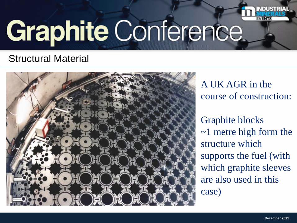
Structural Material
December 2011
A UK AGR in the
course of construction:
Graphite blocks
~1 metre high form the
structure which
supports the fuel (with
which graphite sleeves
are also used in this
case)
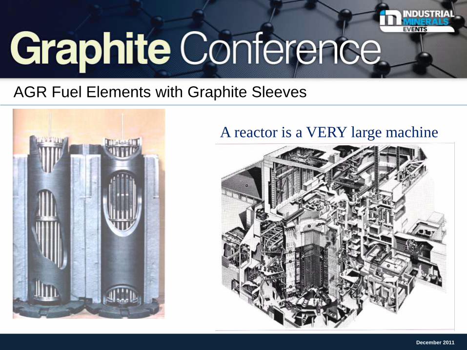
AGR Fuel Elements with Graphite Sleeves
December 2011
A reactor is a VERY large machine
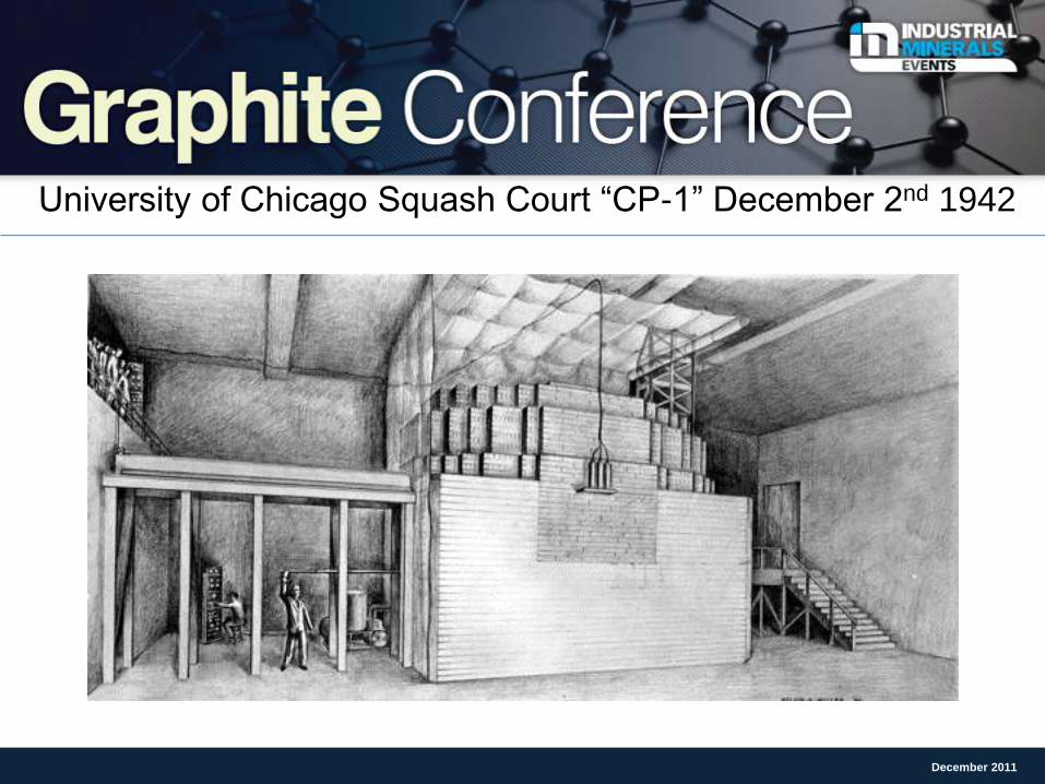
University of Chicago Squash Court “CP-1” December 2nd 1942
December 2011
The Beginning - CP1
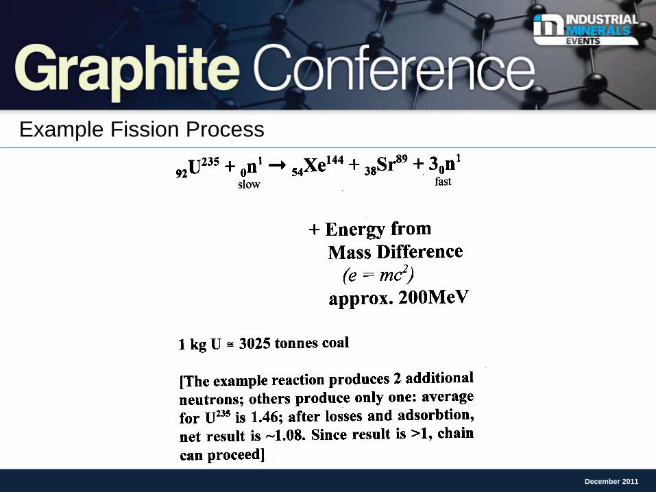
Example Fission Process
December 2011
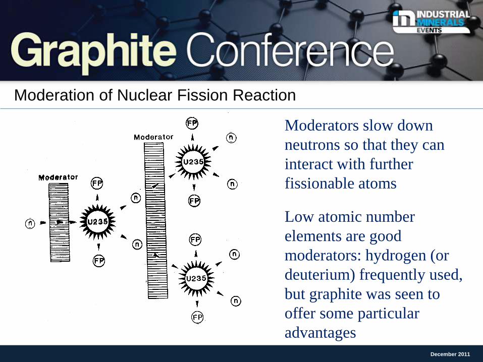
Moderation of Nuclear Fission Reaction
December 2011
Moderators slow down
neutrons so that they can
interact with further
fissionable atoms
Low atomic number
elements are good
moderators: hydrogen (or
deuterium) frequently used,
but graphite was seen to
offer some particular
advantages
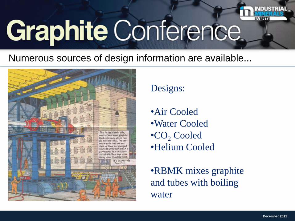
Numerous sources of design information are available...
December 2011
Designs:
•Air Cooled
•Water Cooled
•CO2 Cooled
•Helium Cooled
•RBMK mixes graphite
and tubes with boiling
water
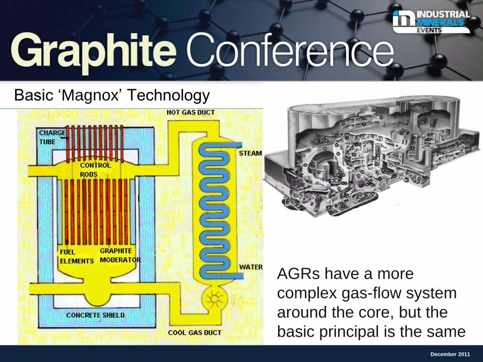
Basic ‘Magnox’ Technology
December 2011
AGRs have a more
complex gas-flow system
around the core, but the
basic principal is the same
Advantages and Disadvantages of Graphite Moderators
Large passive thermal resistance (high heat capacity) gives long period of ‘grace’
to deal with any malfunction such as air ingress to a hot reactor;
AGRs tolerant to significant degradation of the structure;
Can function without enrichment of fuel (e.g. Magnox)
On-load re-fuelling is possible;
BUT...
Classical designs are very large;
Expensive to construct;
Does not utilise the nuclear fuel as efficiently as (for example) water reactors and
fast breeders;
Quite low efficiencies compared with other reactor types (economic issue)
December 2011
Graphite-moderated reactors world-wide (major plant only) UK: 2 small experimental (‘40s); 2 plutonium producers (air cooled - 50s); 24 Magnox
commercial reactors, 1 prototype AGR; 14 AGRs: currently operating 3 Magnox and 14
AGRs (all CO2 cooled)
USA: Early Chicago Piles; 9 Plutonium producers at Hanford, WA, also X-10 in Tennessee –
all closed
France: 3 Plutonium producers and 5 UNGG (rather similar to UK Magnox) – all closed
Italy: 1 UK-designed Magnox reactor (closed)
Japan: 1 UK-designed Magnox reactor (closed); 1 experimental HTR (in operation)
Germany: 2 experimental ‘pebble-bed’ HTR designs (AVR and THTR)
Former USSR: ~6 plutonium producers and 27 RBMKs or forerunner designs thereof
North Korea: 1 plutonium producer: miniature version of UK Calder Hall design
China: a number of essentially defunct plutonium producers; 1 experimental HTR (in
operation); commercial modular HTRs under construction
South Africa designed PBMR but government removed funding December 2011
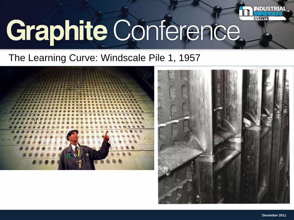
The Learning Curve: Windscale Pile 1, 1957
December 2011
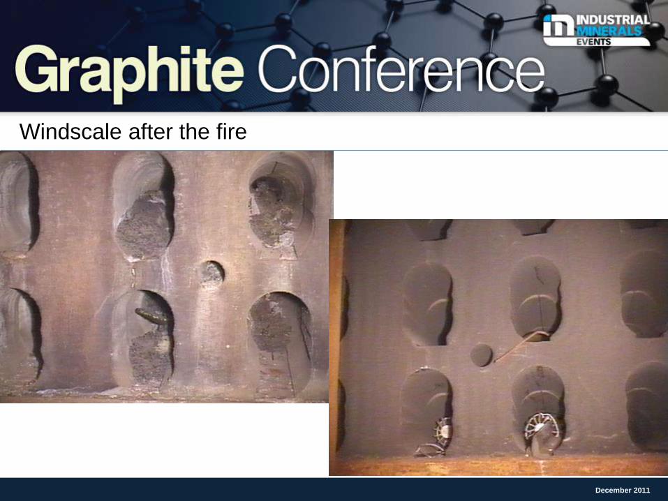
Windscale after the fire
December 2011
Points to note regarding Windscale:
Original cause of the incident was lack of understanding of ‘Wigner energy’ in
which displaced carbon atoms are in higher energy positions than in the normal
hexagonal lattice: this phenomenon is important at low irradiation temperature,
when potential rate of release of energy per unit temperature rise can exceed the
specific heat capacity of the graphite: deliberate anneals ‘went wrong’;
Reducing the air flow allowed temperatures to rise even further whilst increasing
the air flow ‘fanned the flames’; we no longer use such low temperatures, and we
no longer use air as coolant;
Fire originated in failed fuel and isotope cartridges;
Graphite did not burn (you need a temperature in excess of 3300C to achieve
that): the ‘blue flames’ were carbon monoxide burning from the thermally-induced
oxidation reaction (in a limited supply of air)
2C + O2 = 2 CO
December 2011
Looking closer at Nuclear Graphite
December 2011
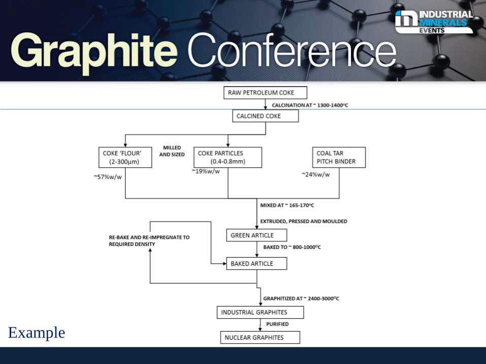
Example
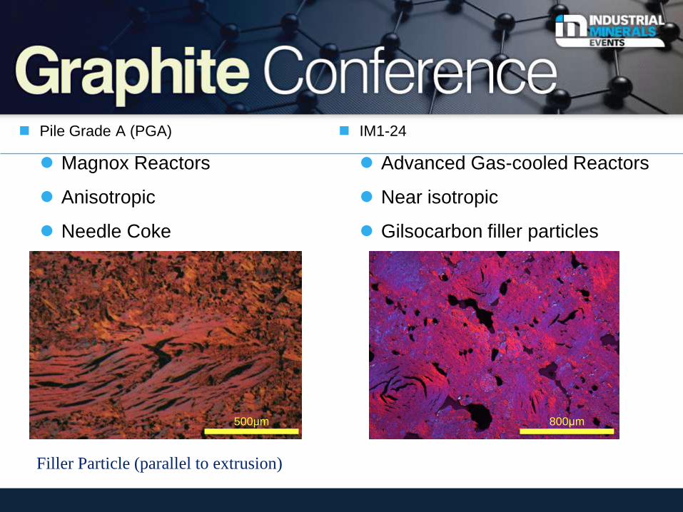
Pile Grade A (PGA)
Magnox Reactors
Anisotropic
Needle Coke
IM1-24
Advanced Gas-cooled Reactors
Near isotropic
Gilsocarbon filler particles
500μm 800μm
Filler Particle (parallel to extrusion)
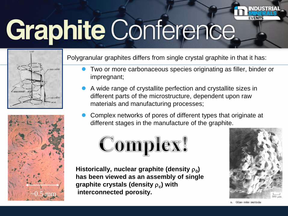
Polygranular graphites differs from single crystal graphite in that it has:
Two or more carbonaceous species originating as filler, binder or
impregnant;
A wide range of crystallite perfection and crystallite sizes in
different parts of the microstructure, dependent upon raw
materials and manufacturing processes;
Complex networks of pores of different types that originate at
different stages in the manufacture of the graphite.
Historically, nuclear graphite (density r0)
has been viewed as an assembly of single
graphite crystals (density rc) with
interconnected porosity.
~0.5 mm
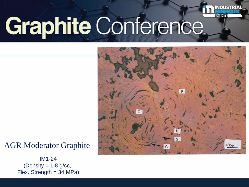
AGR Moderator Graphite
IM1-24
(Density = 1.8 g/cc,
Flex. Strength = 34 MPa)
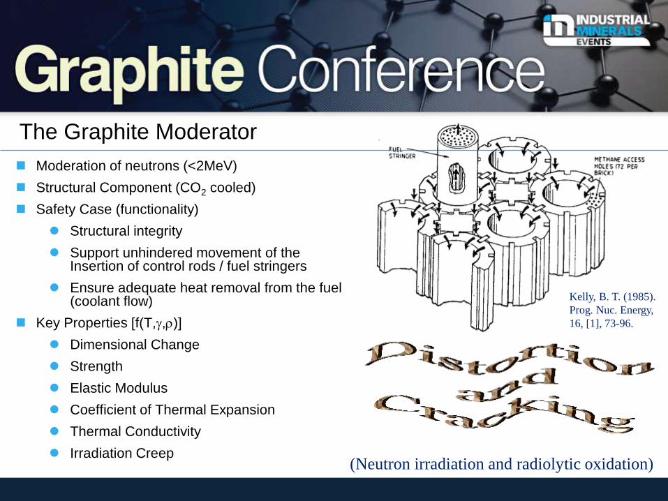
The Graphite Moderator
Moderation of neutrons (<2MeV)
Structural Component (CO2 cooled)
Safety Case (functionality)
Structural integrity
Support unhindered movement of the Insertion of control rods / fuel stringers
Ensure adequate heat removal from the fuel (coolant flow)
Key Properties [f(T,g,r)]
Dimensional Change
Strength
Elastic Modulus
Coefficient of Thermal Expansion
Thermal Conductivity
Irradiation Creep
Kelly, B. T. (1985).
Prog. Nuc. Energy,
16, [1], 73-96.
(Neutron irradiation and radiolytic oxidation)
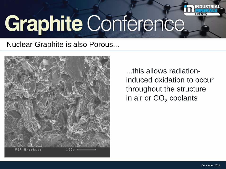
Nuclear Graphite is also Porous...
December 2011
...this allows radiation-
induced oxidation to occur
throughout the structure
in air or CO2 coolants
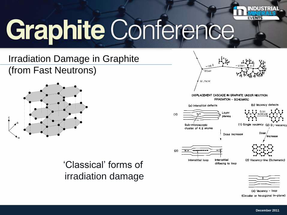
Irradiation Damage in Graphite
(from Fast Neutrons)
December 2011
a
c
a
‘Classical’ forms of
irradiation damage
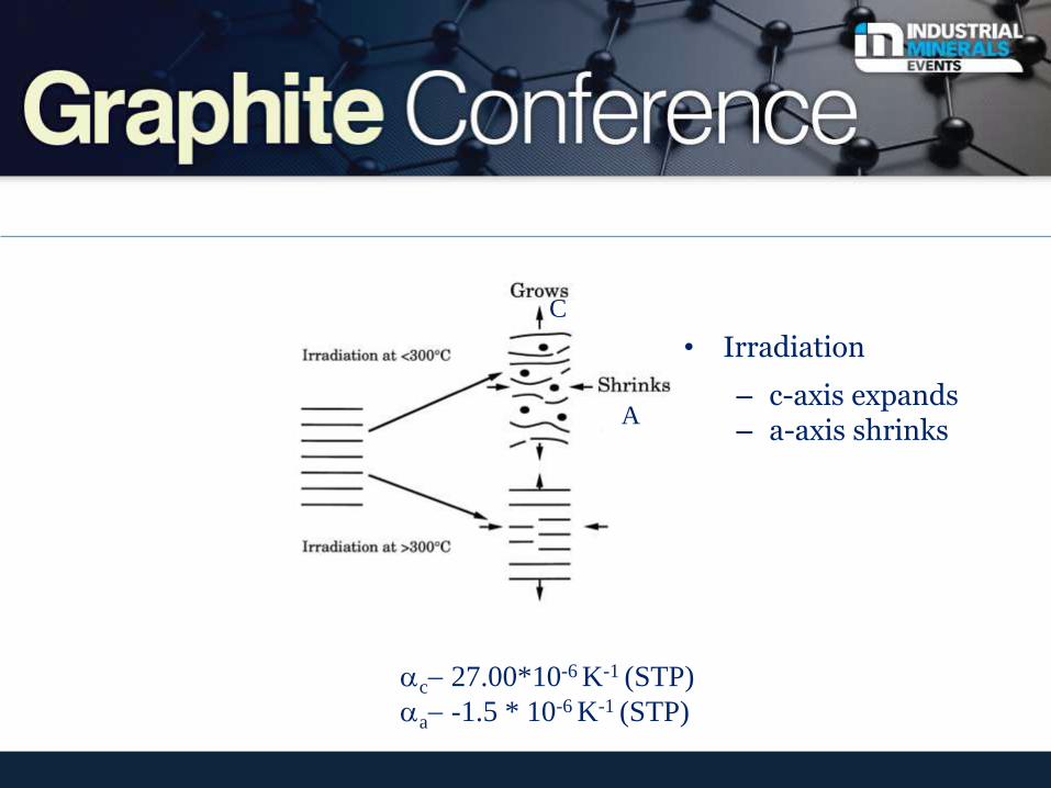
• Irradiation
– c-axis expands – a-axis shrinks
ac- 27.00*10-6 K-1 (STP)
aa- -1.5 * 10-6 K-1 (STP)
C
A
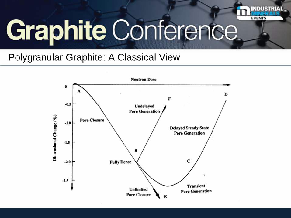
Polygranular Graphite: A Classical View
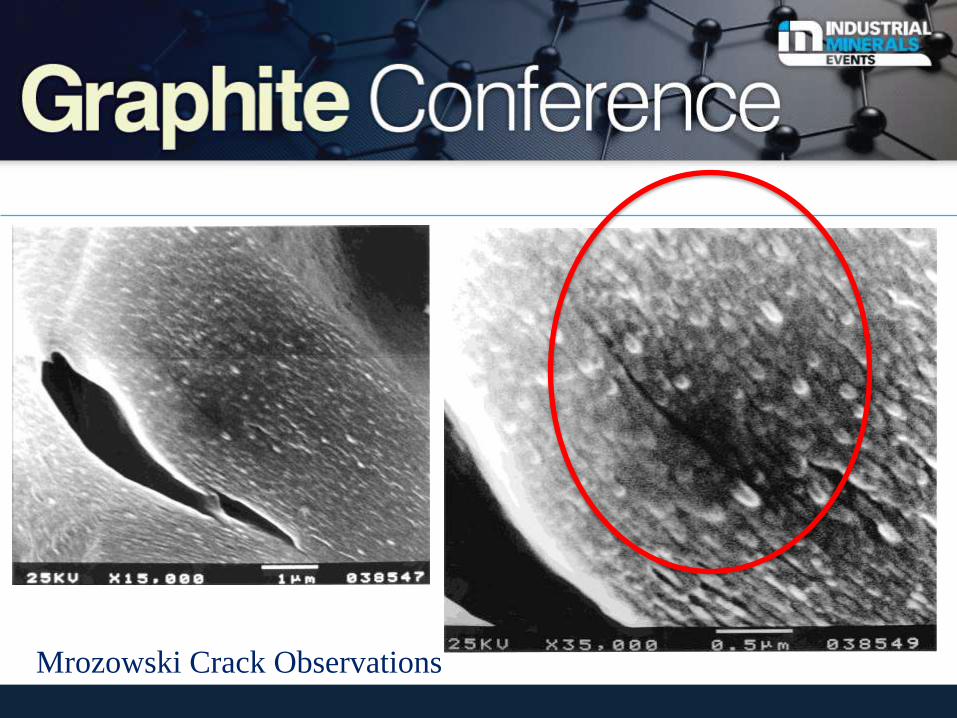
Mrozowski Crack Observations
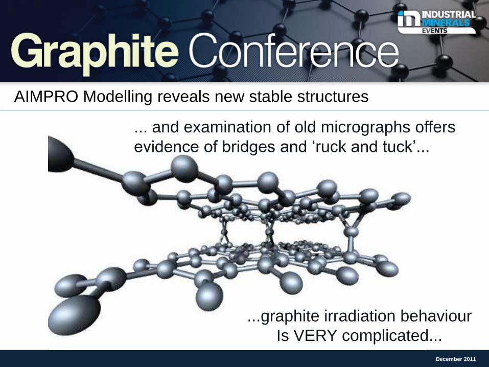
AIMPRO Modelling reveals new stable structures
December 2011
... and examination of old micrographs offers
evidence of bridges and ‘ruck and tuck’...
...graphite irradiation behaviour
Is VERY complicated...
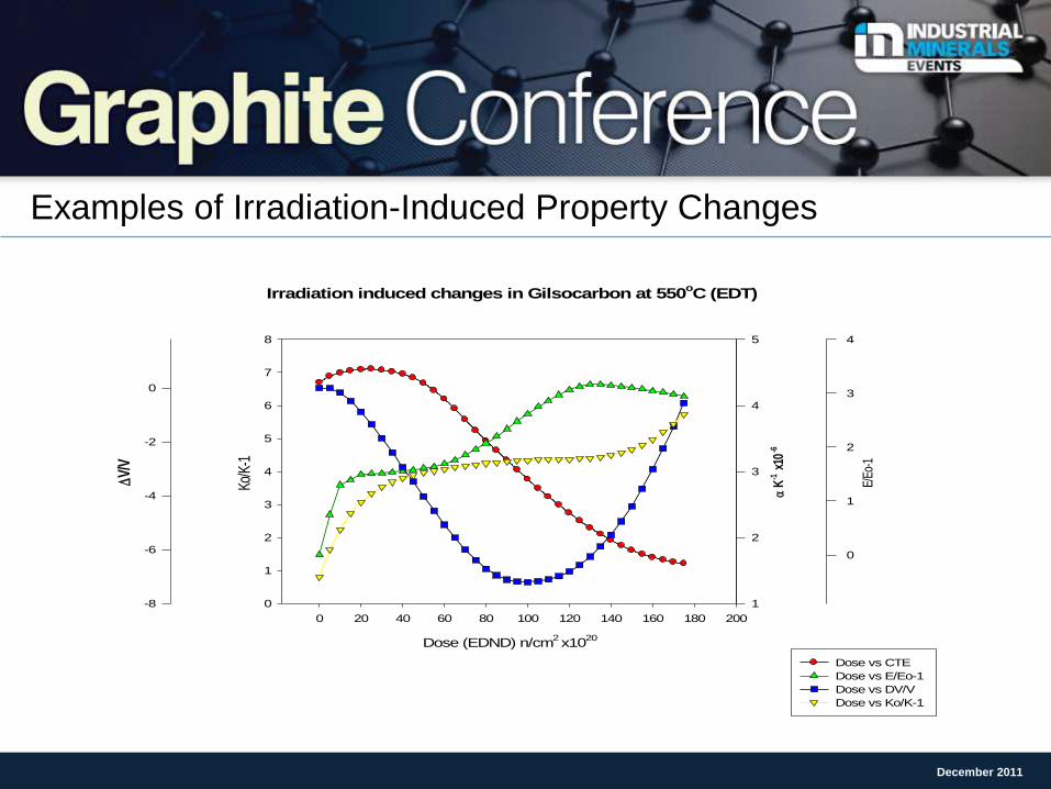
Examples of Irradiation-Induced Property Changes
December 2011
Irradiation induced changes in Gilsocarbon at 550oC (EDT)
Dose (EDND) n/cm2 x10
20
0 20 40 60 80 100 120 140 160 180 200
a K
-1 x1
0-6
1
2
3
4
5
E/Eo
-1
0
1
2
3
4
V/
V
-8
-6
-4
-2
0
Ko/K
-1
0
1
2
3
4
5
6
7
8
Dose vs CTE
Dose vs E/Eo-1
Dose vs DV/V
Dose vs Ko/K-1
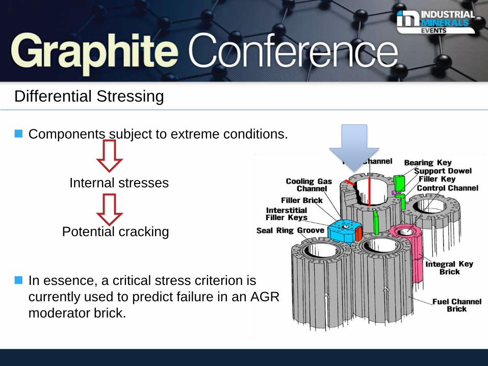
Components subject to extreme conditions.
Internal stresses
Potential cracking
In essence, a critical stress criterion is
currently used to predict failure in an AGR
moderator brick.
Differential Stressing
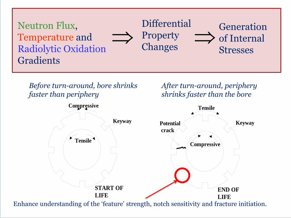
Compressive
Tensile
KeywayPotential
crack
END OF
LIFE
Compressive
Tensile
Keyway
START OF
LIFE
LIFE
Before turn-around, bore shrinks faster than periphery
After turn-around, periphery shrinks faster than the bore
Neutron Flux, Temperature and Radiolytic Oxidation Gradients
Differential Property Changes
Generation of Internal Stresses
Enhance understanding of the ‘feature’ strength, notch sensitivity and fracture initiation.
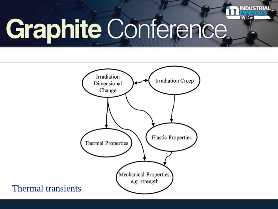
Thermal transients
Ultimately you want …
Fracture model to predict which bricks will fail under reactor
conditions (radiolytic oxidation and neutron irradiation).
Better demonstrate the continued functionality of the reactor core.
Ensure safe operation as well as life extension.
But…!
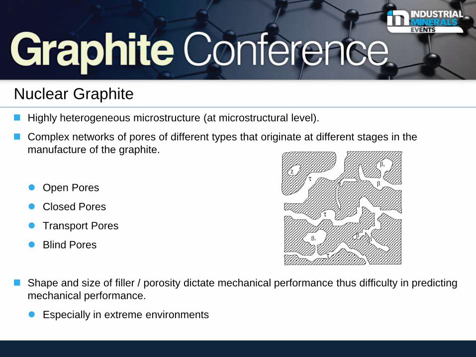
Nuclear Graphite
Highly heterogeneous microstructure (at microstructural level).
Complex networks of pores of different types that originate at different stages in the
manufacture of the graphite.
Open Pores
Closed Pores
Transport Pores
Blind Pores
Shape and size of filler / porosity dictate mechanical performance thus difficulty in predicting
mechanical performance.
Especially in extreme environments
r
r
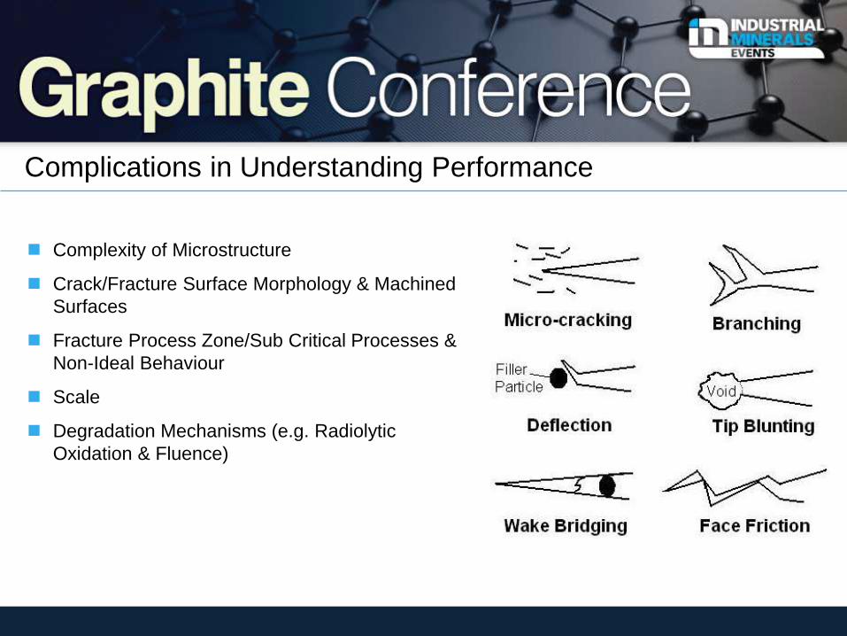
Complexity of Microstructure
Crack/Fracture Surface Morphology & Machined
Surfaces
Fracture Process Zone/Sub Critical Processes &
Non-Ideal Behaviour
Scale
Degradation Mechanisms (e.g. Radiolytic
Oxidation & Fluence)
Complications in Understanding Performance
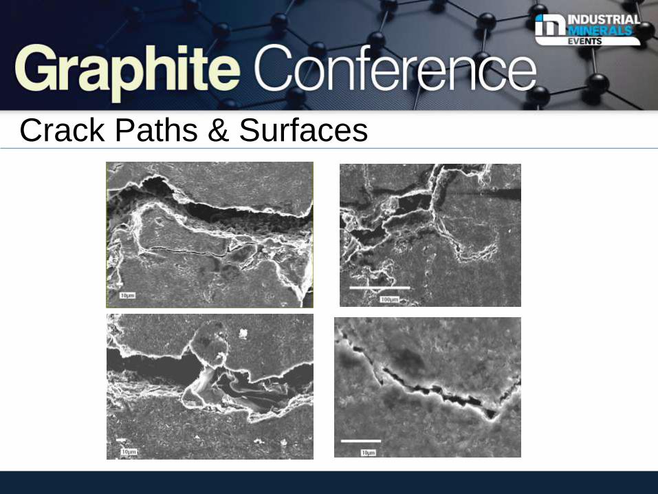
Crack Paths & Surfaces

Polygranular graphite is a quasi-brittle materials just like others!
Examples
Poly-granular graphite
Bone
Concrete (& Rock)
& Others
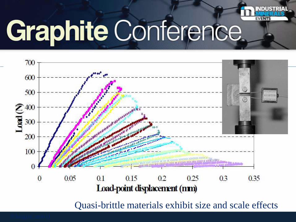
(Ouagne, 2001)
Quasi-brittle materials exhibit size and scale effects
Mic
ros
tru
ctu
re S
imu
lati
on
-Co
mp
uta
tio
nal M
od
el
G
F
B
S
C
P
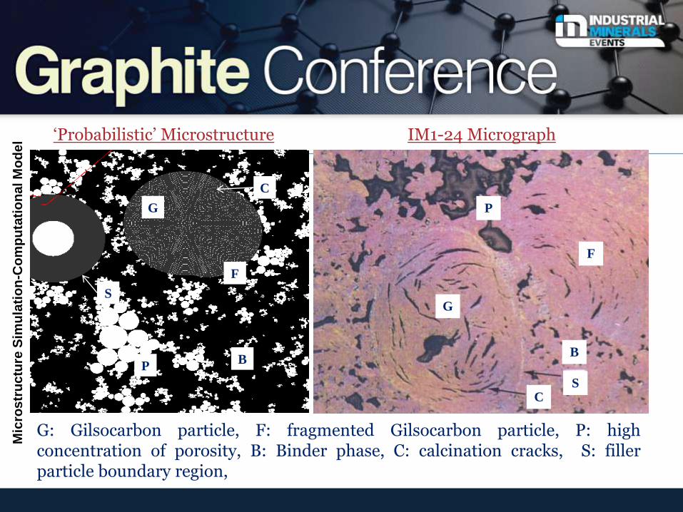
G: Gilsocarbon particle, F: fragmented Gilsocarbon particle, P: high concentration of porosity, B: Binder phase, C: calcination cracks, S: filler particle boundary region,
G
F
B
S C
P
‘Probabilistic’ Microstructure IM1-24 Micrograph
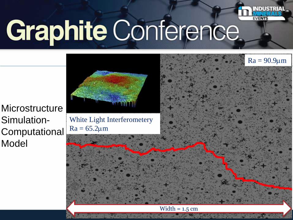
Ra = 90.9mm
White Light Interferometery
Ra = 65.2mm
Width = 1.5 cm
Microstructure
Simulation-
Computational
Model
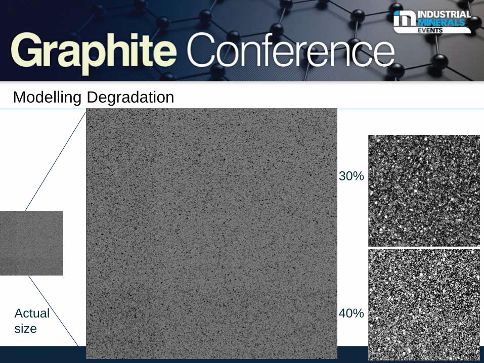
Modelling Degradation
Actual
size
10 cm2
30%
40%
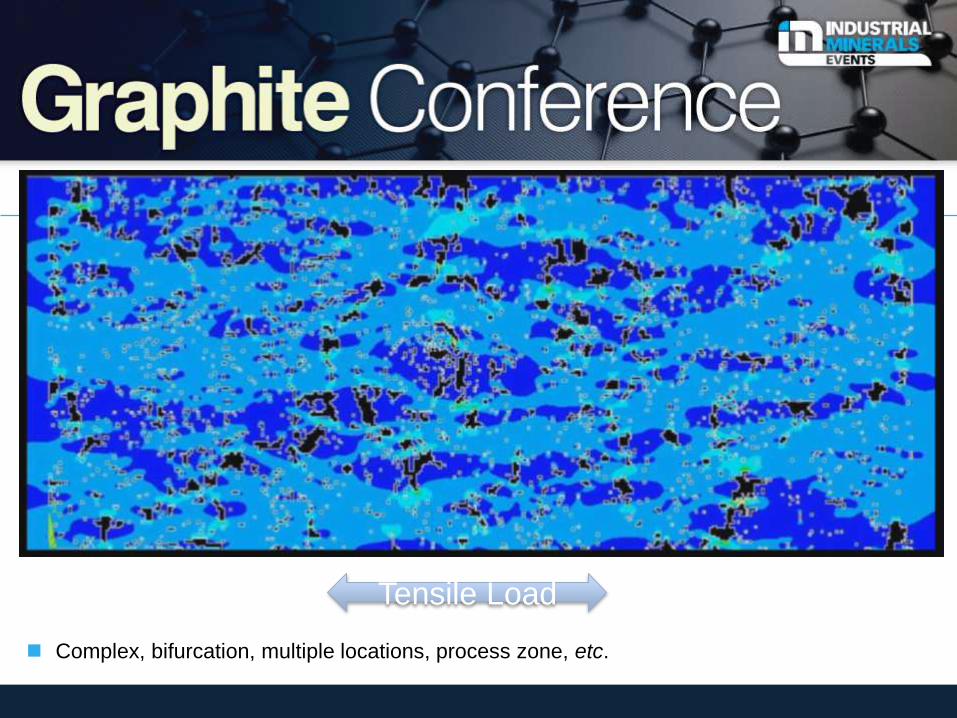
Crack Propagation Through FEA model
Complex, bifurcation, multiple locations, process zone, etc.
Tensile Load
Key Lessons
Graphite is a life limiting issues
Design flaws (sharp corners) / consistent reactor design!
Material selection is extremely important in terms of understanding
performance through life (tailor).
Attention early on for structure-property relationships and multi-scale
principles as well as the inter-relationship of properties.
Need to understand mechanistically the initiation and propagation of
fracture any industrial application of polygranular graphite, especially
NNP, to predict performance and that needs coupling to well
understood plant operating rules.
The Future Reactor Designs?
December 2011
And some lessons!!!
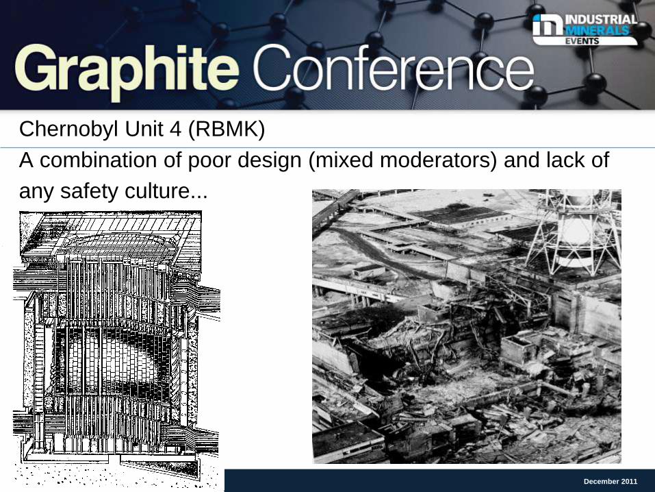
Chernobyl Unit 4 (RBMK)
A combination of poor design (mixed moderators) and lack of
any safety culture...
December 2011
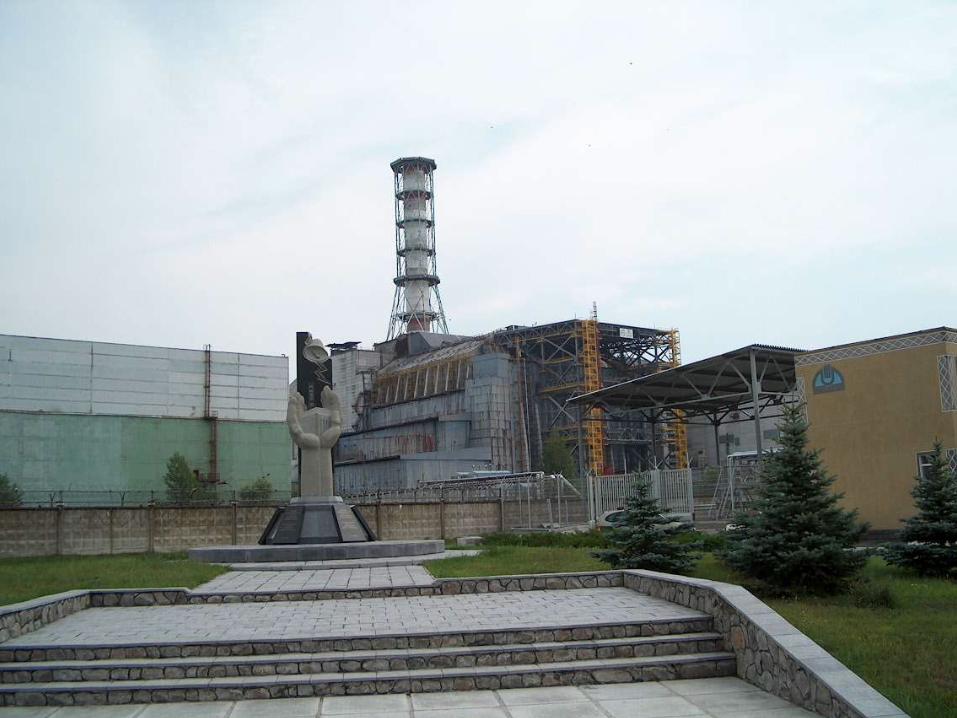
The Chernobyl
Catastrophe: a
prototype
for nuclear terrorism
?
December 2011
December 2011
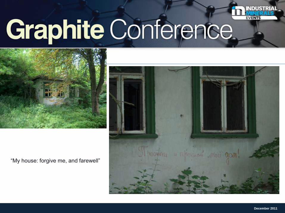
“My house: forgive me, and farewell”
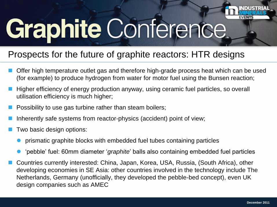
Prospects for the future of graphite reactors: HTR designs
Offer high temperature outlet gas and therefore high-grade process heat which can be used
(for example) to produce hydrogen from water for motor fuel using the Bunsen reaction;
Higher efficiency of energy production anyway, using ceramic fuel particles, so overall
utilisation efficiency is much higher;
Possibility to use gas turbine rather than steam boilers;
Inherently safe systems from reactor-physics (accident) point of view;
Two basic design options:
prismatic graphite blocks with embedded fuel tubes containing particles
‘pebble’ fuel: 60mm diameter ‘graphite’ balls also containing embedded fuel particles
Countries currently interested: China, Japan, Korea, USA, Russia, (South Africa), other
developing economies in SE Asia: other countries involved in the technology include The
Netherlands, Germany (unofficially, they developed the pebble-bed concept), even UK
design companies such as AMEC
December 2011
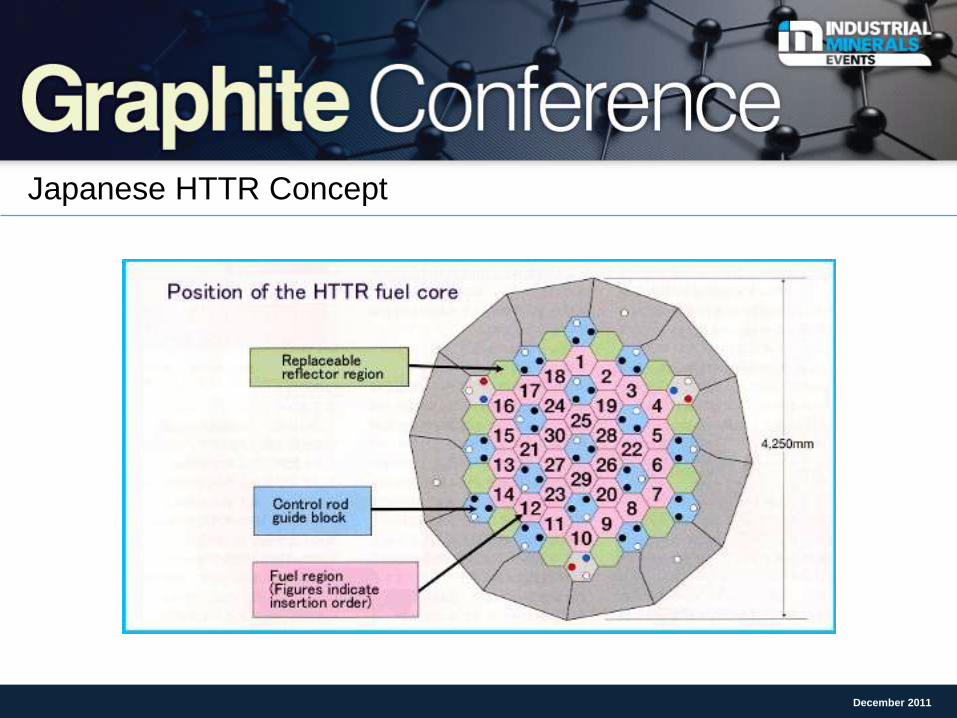
Japanese HTTR Concept
December 2011
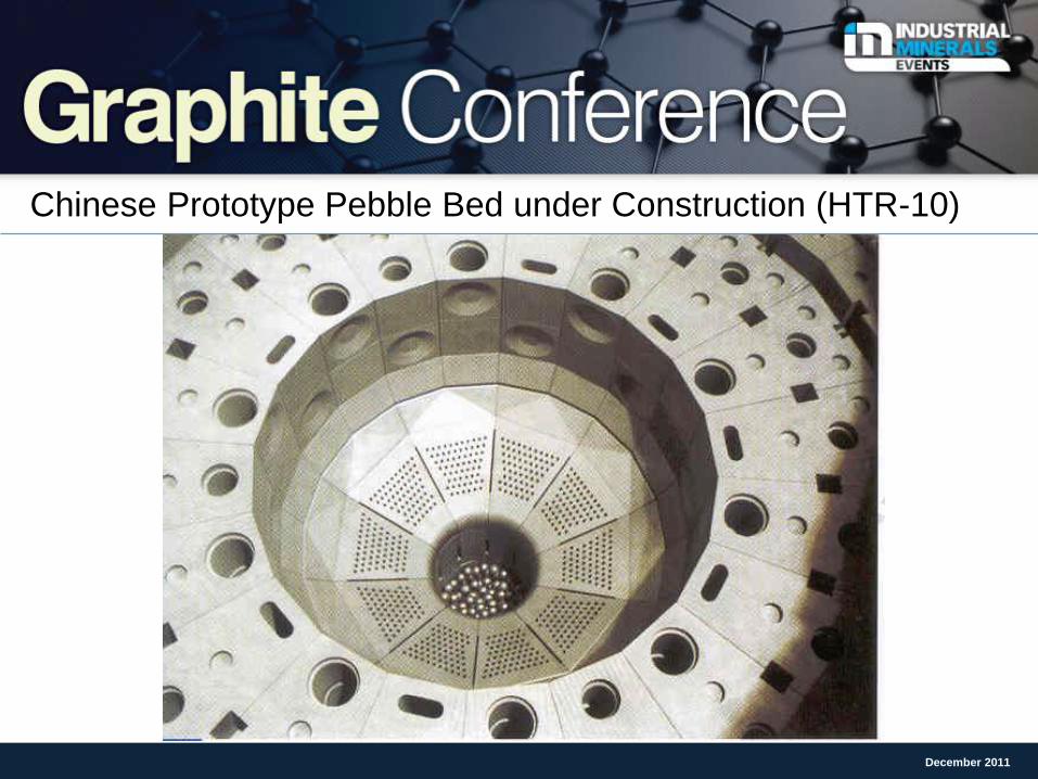
Chinese Prototype Pebble Bed under Construction (HTR-10)
December 2011
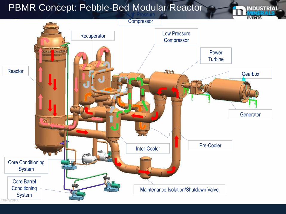
Reactor
Core Barrel
Conditioning
System Maintenance Isolation/Shutdown Valve
Generator
Power
Turbine
Recuperator
High Pressure
Compressor
Low Pressure
Compressor
Gearbox
Inter-Cooler
Core Conditioning
System
Pre-Cooler
PBMR Concept: Pebble-Bed Modular Reactor
Harvesting the Knowledge on Nuclear Graphite
December 2011
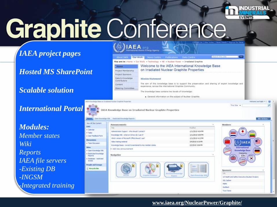
IAEA project pages
Hosted MS SharePoint
Scalable solution
International Portal
Modules: Member states
Wiki
Reports
IAEA file servers
-Existing DB
-INGSM
-Integrated training
www.iaea.org/NuclearPower/Graphite/
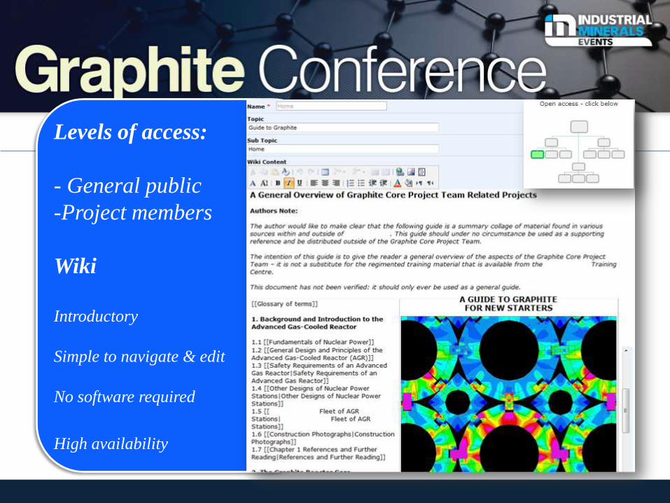
Levels of access:
- General public
-Project members
Wiki
Introductory
Simple to navigate & edit
No software required
High availability
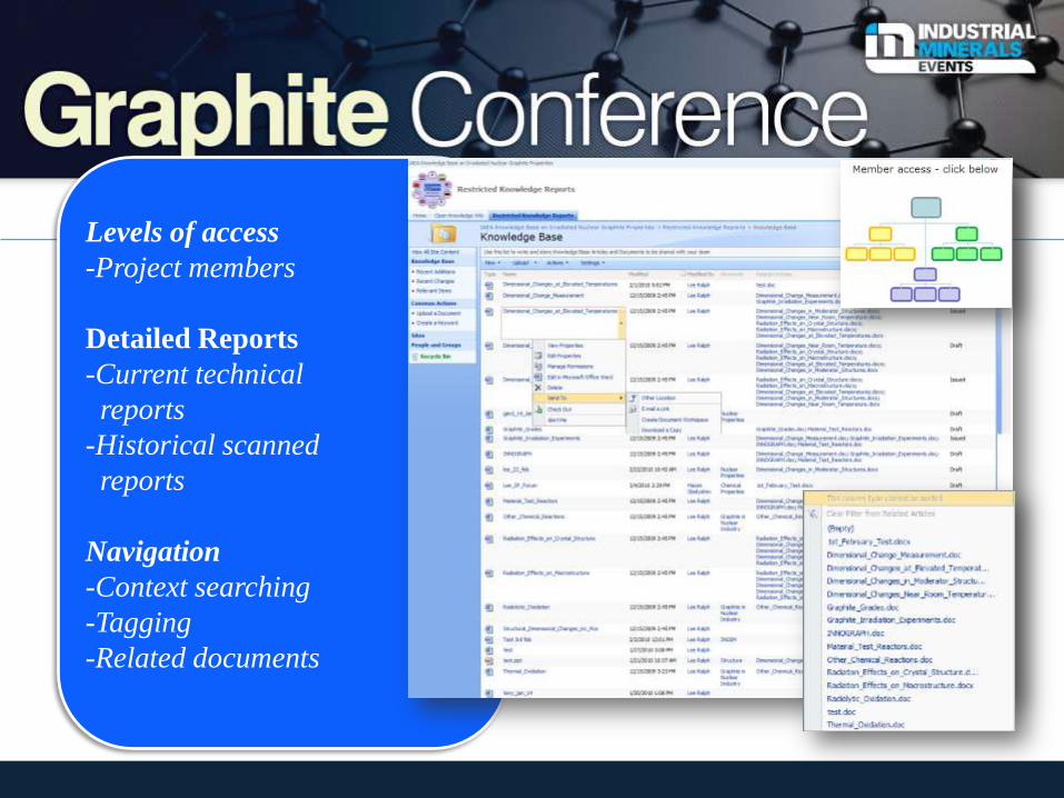
Levels of access
-Project members
Detailed Reports
-Current technical
reports
-Historical scanned
reports
Navigation
-Context searching
-Tagging
-Related documents
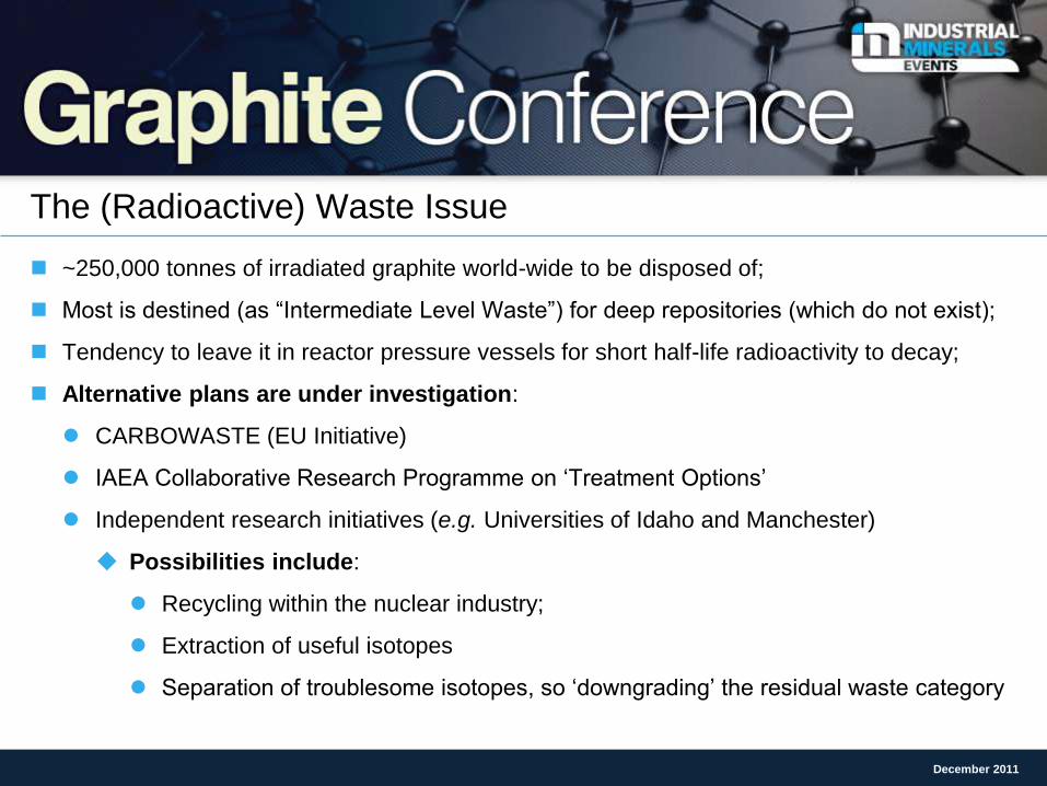
The (Radioactive) Waste Issue
~250,000 tonnes of irradiated graphite world-wide to be disposed of;
Most is destined (as “Intermediate Level Waste”) for deep repositories (which do not exist);
Tendency to leave it in reactor pressure vessels for short half-life radioactivity to decay;
Alternative plans are under investigation:
CARBOWASTE (EU Initiative)
IAEA Collaborative Research Programme on ‘Treatment Options’
Independent research initiatives (e.g. Universities of Idaho and Manchester)
Possibilities include:
Recycling within the nuclear industry;
Extraction of useful isotopes
Separation of troublesome isotopes, so ‘downgrading’ the residual waste category
December 2011
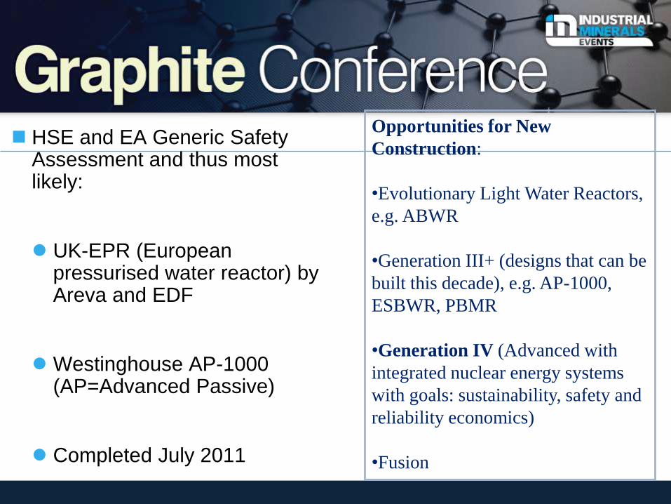
HSE and EA Generic Safety Assessment and thus most likely:
UK-EPR (European pressurised water reactor) by Areva and EDF
Westinghouse AP-1000 (AP=Advanced Passive)
Completed July 2011
Opportunities for New
Construction:
•Evolutionary Light Water Reactors,
e.g. ABWR
•Generation III+ (designs that can be
built this decade), e.g. AP-1000,
ESBWR, PBMR
•Generation IV (Advanced with
integrated nuclear energy systems
with goals: sustainability, safety and
reliability economics)
•Fusion
How ‘Green’ is this?
December 2011
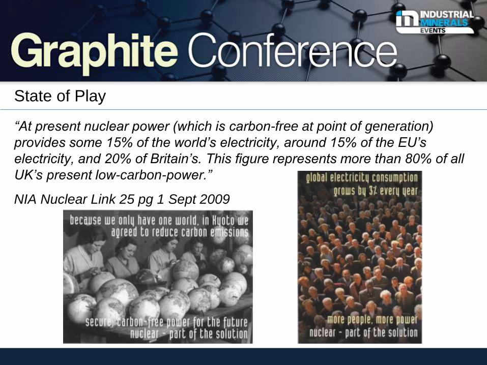
State of Play
“At present nuclear power (which is carbon-free at point of generation)
provides some 15% of the world’s electricity, around 15% of the EU’s
electricity, and 20% of Britain’s. This figure represents more than 80% of all
UK’s present low-carbon-power.”
NIA Nuclear Link 25 pg 1 Sept 2009
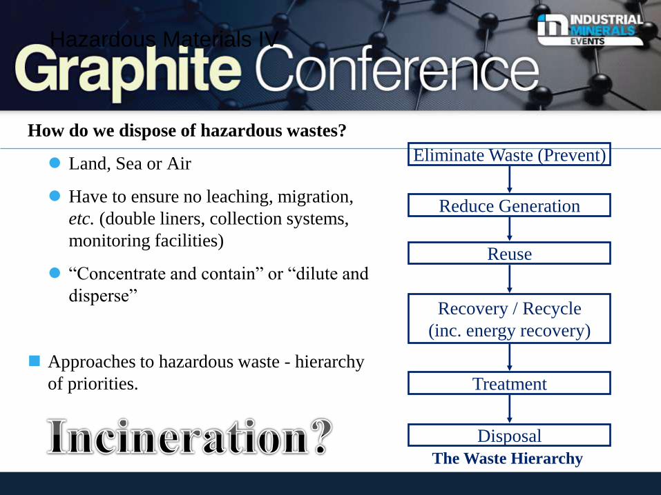
Hazardous Materials IV
How do we dispose of hazardous wastes?
Land, Sea or Air
Have to ensure no leaching, migration,
etc. (double liners, collection systems,
monitoring facilities)
“Concentrate and contain” or “dilute and
disperse”
Approaches to hazardous waste - hierarchy
of priorities.
Eliminate Waste (Prevent)
Reduce Generation
Recovery / Recycle
(inc. energy recovery)
Treatment
Disposal
Reuse
The Waste Hierarchy
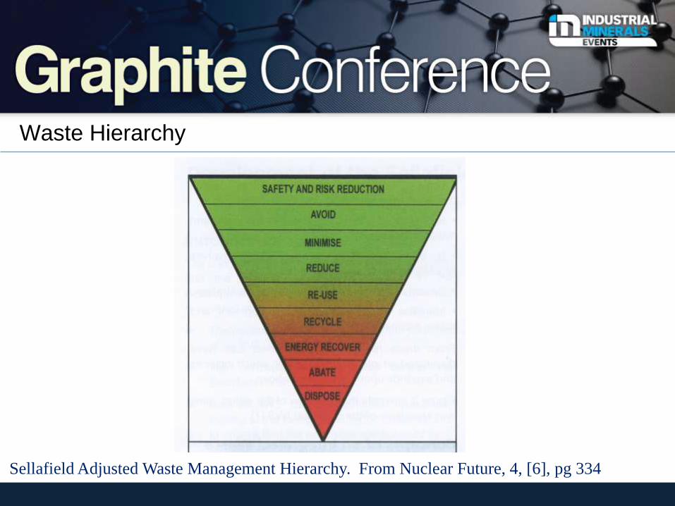
Waste Hierarchy
Sellafield Adjusted Waste Management Hierarchy. From Nuclear Future, 4, [6], pg 334
Sustainability
Managing to be environmentally responsive
Given that our planet is not a sustainable system by itself, a sustainable product is a
product, which will give as little impact on the environment as possible during its lifecycle.
Sustainability is (i) doing the right thing and (ii) doing the thing right!.
In order to be sustainable, accepted actions should be 'environmentally sustainable,
economically viable, technologically feasible, socially desirable/tolerable, legally
permissible, administratively achievable and politically expedient. In other words, “Use
and development that meets today’s needs without preventing those needs from being
met by future generations”. Sustainability encompasses the Triple Bottom Line of
economic, environmental and social responsibility. In other words it involves human,
financial and natural capital.
Datschefski’s “the total beauty of sustainable products”. He found that 99% of all
environmental innovations use one or more of these five principles: cyclic; solar; safe;
efficient; social.
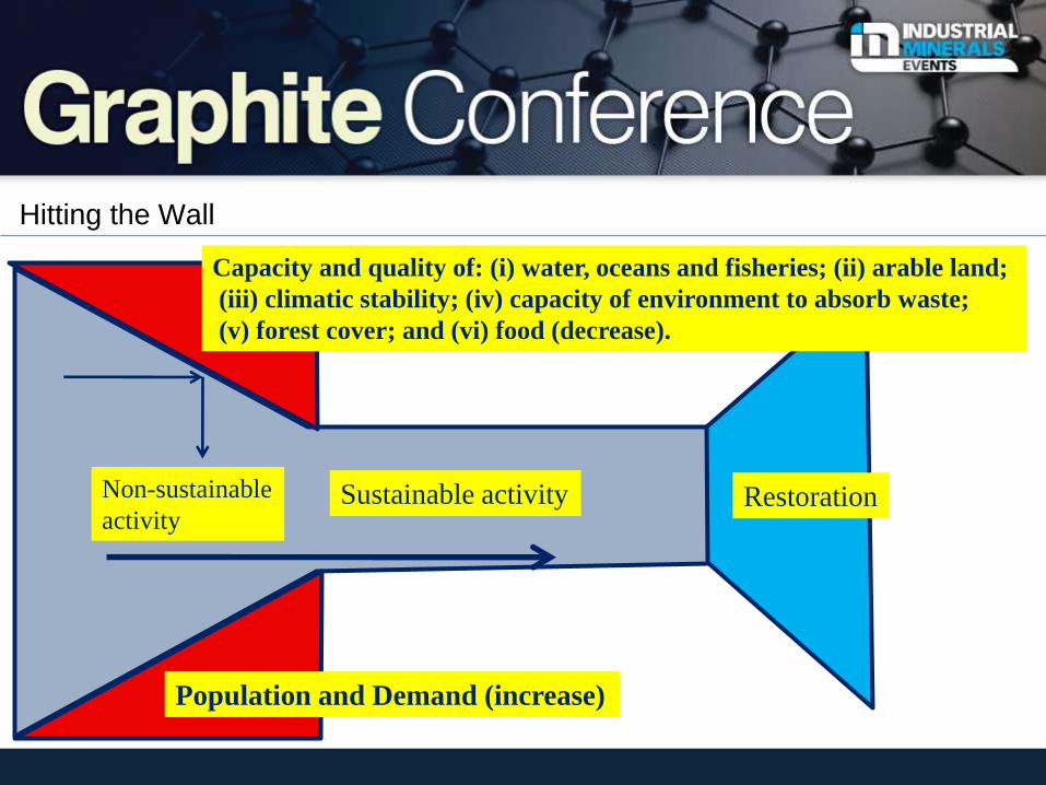
Hitting the Wall
Non-sustainable
activity Sustainable activity Restoration
Population and Demand (increase)
Capacity and quality of: (i) water, oceans and fisheries; (ii) arable land;
(iii) climatic stability; (iv) capacity of environment to absorb waste;
(v) forest cover; and (vi) food (decrease).
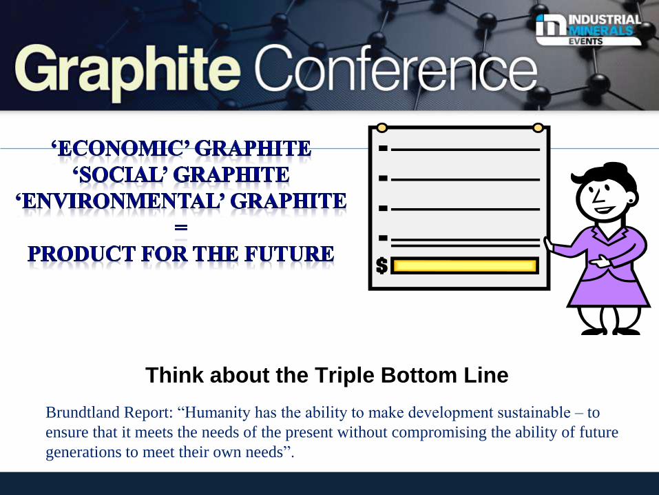
Think about the Triple Bottom Line
Brundtland Report: “Humanity has the ability to make development sustainable – to
ensure that it meets the needs of the present without compromising the ability of future
generations to meet their own needs”.
December 2011