nstx nstx upgrade project final design and cd-3 readiness review june 22 - 24th 2011 1 nstx...
TRANSCRIPT

NSTXNSTX NSTX Upgrade Project Final Design and CD-3 Readiness Review June 22 - 24th 2011 1
NSTXNSTX Supported by
College W&MColorado Sch MinesColumbia UCompXGeneral AtomicsINELJohns Hopkins ULANLLLNLLodestarMITNova PhotonicsNew York UOld Dominion UORNLPPPLPSIPrinceton UPurdue USNLThink Tank, Inc.UC DavisUC IrvineUCLAUCSDU ColoradoU IllinoisU MarylandU RochesterU WashingtonU Wisconsin
Digital Coil Protection System
Culham Sci CtrU St. Andrews
York UChubu UFukui U
Hiroshima UHyogo UKyoto U
Kyushu UKyushu Tokai U
NIFSNiigata UU Tokyo
JAEAHebrew UIoffe Inst
RRC Kurchatov InstTRINITI
KBSIKAIST
POSTECHASIPP
ENEA, FrascatiCEA, Cadarache
IPP, JülichIPP, Garching
ASCR, Czech RepU Quebec
R.E. HatcherJ. Lawson, R. Mozulay, R. Woolley
Princeton Plasma Physics LaboratoryNSTX Upgrade ProjectFinal Design Review
LSB, B318June 22-24, 2011

NSTXNSTX NSTX Upgrade Project Final Design and CD-3 Readiness Review June 22 - 24th 2011
Background (Why?)
2
• Operating envelope of NSTX_CSU significantly greater than that of NSTX
• Expansion is due to increased magnetic field strength (coil currents), changes to device geometry, new coils systems, increased pulse length, and new operating scenarios
• New operating scenarios can result in forces, temperatures, and stresses to both the coils and mechanical structures that significantly exceed NSTX design limits
• Access to full operating space would result in compromised structural integrity and in some cases could cause catastrophic failure
• Mechanical solution alone is not feasible (complicated design, cost, schedule, and flexibility) and separate systems and limits can result in severe operating space limitations (e.g., NSTX PF4-PF5 simultaneous operation)
• Project is determining critical set of values (forces, stresses, temperatures, combinations) that combined with their derivatives define the machine “state” with respect to machine integrity

NSTXNSTX NSTX Upgrade Project Final Design and CD-3 Readiness Review June 22 - 24th 2011
Progress
3
• Starting Final Design (delayed project start to ensure total scope defined)
• Successful CDR 3/2011 – all chits resolved
• Reached out to other installations (C-Mod and DIII-D) to “see what others are doing”
• Preliminary system design (with drawings) complete
• List of protection variables (some algorithms) from analysts
• Recently completed PDR with external reviewer (W. Burke – C-Mod)
• Work started on Systems Code
• Commencing PDR chit resolution and Final Design – FDR in 2012

NSTXNSTX NSTX Upgrade Project Final Design and CD-3 Readiness Review June 22 - 24th 2011
Requirements
4
• DCPS ↔ real-time machine integrity determination and protection utilizing fast programmable digital system
• Protection is in “real-time”
• The “state” (protection values and their derivatives) is continuously calculated on high-speed digital computer system and compared to pre-defined limits (like the current NSTX ISTP-001)
• Algorithms will provide both instantaneous protection but also protect in a “first derivative” sense
• Will not allow successive “full power” plasma attempts at a rate that exceeds the basic duty cycle of the NSTX_CSU (5 s / 1200 s = 0.4 %)
• Basic calculation interval similar to power supply response time (O(ms)) or less

NSTXNSTX NSTX Upgrade Project Final Design and CD-3 Readiness Review June 22 - 24th 2011
Requirements
5
• DCPS operation will be fail safe. It will be impossible to run the machine with the DCPS either faulted or in a powered off state
• Protection will be effected via interface to existing Level 1 fault system
• Any fault or failure on any DCPS unit will be considered genuine and cause a Level 1 fault
• The DCPS will be a “standalone” system with respect to the laboratory network (security)
• Where reasonable, “off the shelf” industry standard components will be used
• Hardware and software design to allow for future expansion

NSTXNSTX NSTX Upgrade Project Final Design and CD-3 Readiness Review June 22 - 24th 2011
Benefits
6
• Easy reconfiguration – the DCPS algorithms and interlock limits can be easily changed in response to changing experimental requirements or changes in the state of the protected hardware
• The DCPS is capable of monitoring and interlocking a set intersecting/competing objectives with both unmatched accuracy and redundancy
• Algorithms can be exercised off-line for both post-shot evaluative analysis and for scenario development
• The DCPS can provide data to other processes (psc, psrtc, etc.) that can be used to modify process behavior (future)
• New protection algorithms can be easily added to meet future needs
NSTXNSTX NSTX Upgrade Project Final Design and CD-3 Readiness Review June 22 - 24th 2011
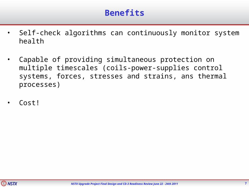
Benefits
7
• Self-check algorithms can continuously monitor system health
• Capable of providing simultaneous protection on multiple timescales (coils-power-supplies control systems, forces, stresses and strains, ans thermal processes)
• Cost!

NSTXNSTX NSTX Upgrade Project Final Design and CD-3 Readiness Review June 22 - 24th 2011
Schedule & Est. Cost
8
• Final design complete – Summer 2012
• Systems code complete – Summer 2012
• Algorithm documentation complete – Spring 2012
• Real-time programming start – Fall 2013
• Testing – Winter/Spring 2014
• Project Complete: Spring 2014
• Estimated Total Project Cost: ~ $1.8 M

NSTXNSTX NSTX Upgrade Project Final Design and CD-3 Readiness Review June 22 - 24th 2011
Successful CDR 3/2011
9
Chit Concern/Recommendation Comment/Action1 The DCPS does not address the use of fiber-optic sensors to
monitor the stress/strain and temperature of actual coils. It would be foolish to repeat the mistakes of the TF joint problems. Fiber-optic sensor installation affects the actual design of the coil/center stack. These fiber-optic signals could greatly benefit the DCPS.
This chit was considered out of scope for this review since no direct coil stress monitoring has been prescribed in the center stack design. However, analog inputs to the DCPS are available if needed to validate engineering models
2 Would be good if there is an easily understood post-processor to quickly determine in the control room why a level 1 fault was issued. COE needs to be able to determine what "broke"
Concur. Action: R. Hatcher to consider
3 Why are we using NI digitizers for inputs. We have qualified the FPDP data stream, with SADS, in the NSTX environment. We have also developed computing methods with ACQ & PCS. Shouldn't we take advantage of this experience.
Commercially "standard" approaches were found to be adequate for this application. Action: J. Lawson to evaluate further and review with the IT Division.
4 The protection list should identify and include the weakest link in the power loop (not just the coil itself)
The design of the DCPS focuses on machine protection and assumes that local systems protect components in the power loop. Action: R. Hatcher to consider.
5 Can we provide additional instrumentation to validate engineering models.
Similar to Chit#1.
6 A permissive is to be provided to FCPC rectifier circuits to insure DCPS is ready.
Concur, but believe that the DCPS output serves both as a permissive and a fault signal. Action: R. Hatcher to evaluate.
7 Provide a list of DCPS inputs and outputs from and to the DCPS. Concur. Action: R. Hatcher to provide for the PDR.
8 Software requirement: Regression testing and models or simulator should be available to validate the vast number of coefficients and settings.
Concur. Simulation tests to be developed for all inputs. Action: R. Hatcher
9 The conceptual hardware/computing block diagram, the proposed implementation, is a questionable approach. Consider a separate discussion of approaches (VME, SAD, LabView RT/FPGA)
Agreed. Action: J. Lawson to discuss with IT
10 This will be the most critical system on the lab network. Address the cyber security plan in the PDR. The dire consequence of unauthorized code changes warrant this topic be addressed. Consider not having this system on the network.
Concur. Action: J. Lawson
11 PCS & PSC (PSRTC) traditionally have provided computations to "back-up" the hardware protection systems. Will the DCPS place similar new requirements on PCS/PSC? Will the existing PSC protective algorithms require any changes for DCPS?
No impact to PCS is expected, but will possible affect PSC (PSTRC). Action: R. Hatcher to coordinate with IT.
12 Clarify what changes to PSRTC will happen due to the DCPS installation. Document changes and inform people.
See Chit #11
13 Consider adding supplemental DAC outputs for the real time or CAMAC digitizers. For post-mortem analysis or for alerting PCS/PSC if status in real time.
Concur. Action: J. Lawson to consider in preparing preliminary design.
14 The PDR should address test and validation of the system. Concur. Action: R. Hatcher
NSTXNSTX NSTX Upgrade Project Final Design and CD-3 Readiness Review June 22 - 24th 2011
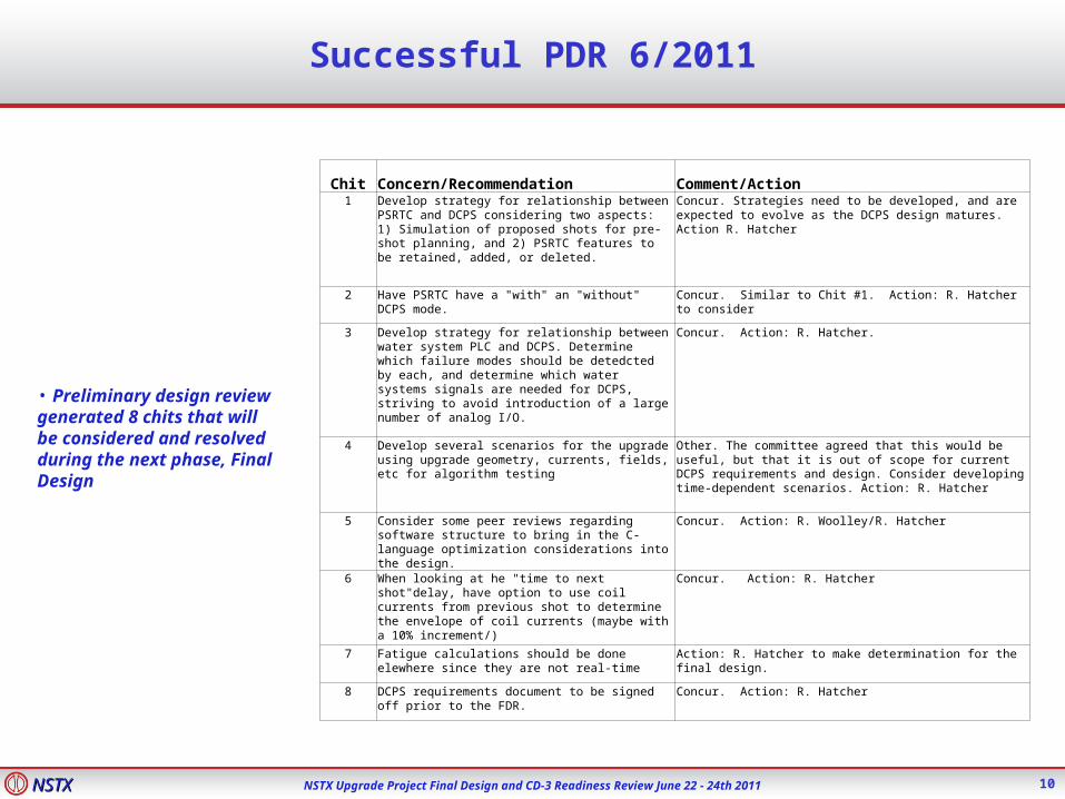
Successful PDR 6/2011
10
• Preliminary design review generated 8 chits that will be considered and resolved during the next phase, Final Design
Chit Concern/Recommendation Comment/Action1 Develop strategy for relationship between PSRTC
and DCPS considering two aspects: 1) Simulation of proposed shots for pre-shot planning, and 2) PSRTC features to be retained, added, or deleted.
Concur. Strategies need to be developed, and are expected to evolve as the DCPS design matures. Action R. Hatcher
2 Have PSRTC have a "with" an "without" DCPS mode.
Concur. Similar to Chit #1. Action: R. Hatcher to consider
3 Develop strategy for relationship between water system PLC and DCPS. Determine which failure modes should be detedcted by each, and determine which water systems signals are needed for DCPS, striving to avoid introduction of a large number of analog I/O.
Concur. Action: R. Hatcher.
4 Develop several scenarios for the upgrade using upgrade geometry, currents, fields, etc for algorithm testing
Other. The committee agreed that this would be useful, but that it is out of scope for current DCPS requirements and design. Consider developing time-dependent scenarios. Action: R. Hatcher
5 Consider some peer reviews regarding software structure to bring in the C-language optimization considerations into the design.
Concur. Action: R. Woolley/R. Hatcher
6 When looking at he "time to next shot"delay, have option to use coil currents from previous shot to determine the envelope of coil currents (maybe with a 10% increment/)
Concur. Action: R. Hatcher
7 Fatigue calculations should be done elewhere since they are not real-time
Action: R. Hatcher to make determination for the final design.
8 DCPS requirements document to be signed off prior to the FDR.
Concur. Action: R. Hatcher

NSTXNSTX NSTX Upgrade Project Final Design and CD-3 Readiness Review June 22 - 24th 2011
Design
11
• The DCPS will use redundancy, to the greatest extent possible, to increase reliability
• Software will be written in modern, structured programming language
• Software to include data archive and restore functionality
• Fault causing self-check features will used in both hardware and software
• A DCPS “post-processor” will be included to assist the operators in determining the cause of a fault
• A software test suite will be used to validate DCPS functionality (e.g., regression testing after changes)
• Located indoors within a climate controlled environment (FCPC junction area) with a maximum temperature of 24 ºC
•

NSTXNSTX NSTX Upgrade Project Final Design and CD-3 Readiness Review June 22 - 24th 2011
Protection List
12
• PF coil supports
• Bus Bar stresses
• Outer leg insulation bond shear
• PF2 bracket and bolt stress
• PF3 bracket and weld stress
• Torques and stresses lid and spoke assembly (upper & lower)
• Vacuum vessel leg torque
• TF outer leg torque
• Axial forces on PF coils (single and combination)
• PF Coil moments (torque)
• Dome and PF rib stresses
• Coil thermal stresses
• Lid torque
• Leg and brace Hilti’s™ (loads and moments)
• Knuckle clevis loads
• Ring loads and moments
• TF teeth torque
• TF joint bolts stresses
• Umbrella structure reinforcement (stress)
• OOP TF torque
• TF joint (forces, torques)
• TF coil torsional shear stress
• OH fatigue (long term)
• TF shear forces between TF turns, insulation, and insulating crown
• Coil temperatures (i2t heating)

NSTXNSTX NSTX Upgrade Project Final Design and CD-3 Readiness Review June 22 - 24th 2011
Protection at Other Facilities
13
• DIII-D• Immediate “abort” (shutdown all power systems
and short the OH coil) and “next shot prevention” protection
• Thermally, the coils should be able to withstand the heat from one shot if cooling is lost during the shot (if the coil has totally cooled down from the previous shot)
• Coil Monitoring
• Ground Fault• Over current• Coil coolant flow• Coil coolant pressure• Coil outlet coolant temperature• Coil conductor temperature
• B-coil (TF) bundle deflection• B-coil center post twist• B-coil pre-stress monitoring
• Other (undocumented)
• C-Mod• Multiple non-integrated systems
• Coil temperature monitoring
• Real-time I2t calculation and temperature modeling (microcontrollers)
• OH force monitors (analog)
• Over current protection
• RF coupler protection
• RF transmitter protection (in design phase)
• Other (undocumented)
NSTXNSTX NSTX Upgrade Project Final Design and CD-3 Readiness Review June 22 - 24th 2011
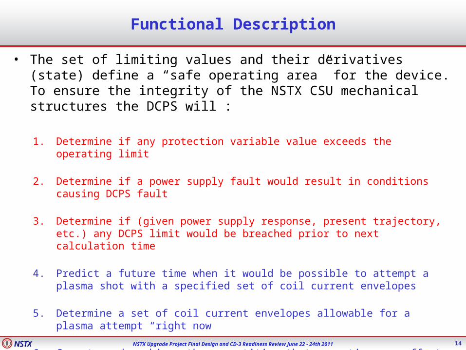
Functional Description
14
• The set of limiting values and their derivatives (state) define a “safe operating area” for the device. To ensure the integrity of the NSTX CSU mechanical structures the DCPS will :
1. Determine if any protection variable value exceeds the operating limit
2. Determine if a power supply fault would result in conditions causing DCPS fault
3. Determine if (given power supply response, present trajectory, etc.) any DCPS limit would be breached prior to next calculation time
4. Predict a future time when it would be possible to attempt a plasma shot with a specified set of coil current envelopes
5. Determine a set of coil current envelopes allowable for a plasma attempt “right now
6. Compute and archive other quantities that over time can affect machine integrity because of fatigue
7. Evaluate acceptability of potential operating scenarios (static and transient) for a given DCPS configuration

NSTXNSTX NSTX Upgrade Project Final Design and CD-3 Readiness Review June 22 - 24th 2011
Present (preliminary) Design
15
There will be two identical DCPS units. Each unit will support 64 analog and up to 96 digital I/O channels
INPUTS– Analog signals – all PF and TF currents, primary coil coolant flow rate,
coolant t temperature, main cooling system pressure
– Digital signals – status bits from other systems
– All inputs will have over/under-voltage protection
– All inputs will be electrically isolated from the DCPS (e.g., optically coupled)
– Digital Inputs: 5 V (TTL) or 24 V (high noise immunity)
– Analog Inputs: ±10 V 4 kHz anti-aliasing filter cable fault detection
– Reset Input: digital input (local pushbutton or remote electrical signal –
FAULT HAS PRECEDENCE
NSTXNSTX NSTX Upgrade Project Final Design and CD-3 Readiness Review June 22 - 24th 2011
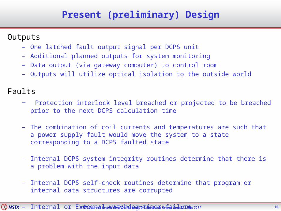
Present (preliminary) Design
16
Outputs– One latched fault output signal per DCPS unit– Additional planned outputs for system monitoring– Data output (via gateway computer) to control room– Outputs will utilize optical isolation to the outside world
Faults– Protection interlock level breached or projected to be breached prior to the next DCPS
calculation time
– The combination of coil currents and temperatures are such that a power supply fault would move the system to a state corresponding to a DCPS faulted state
– Internal DCPS system integrity routines determine that there is a problem with the input data
– Internal DCPS self-check routines determine that program or internal data structures are corrupted
– Internal or External watchdog timer failure

NSTXNSTX NSTX Upgrade Project Final Design and CD-3 Readiness Review June 22 - 24th 2011
Block Diagram with DCPS
17
Level 1FLT
FCPC
Analog Data In
Digital Data In
Plasma Diagnostics
DCPS
PCSPSRTC
NSTX CSU
DCPS #1
DCPS #2

NSTXNSTX NSTX Upgrade Project Final Design and CD-3 Readiness Review June 22 - 24th 2011
DCPS Hardware
18
• Two identical redundant active DCPS units
• Eight, 8-channel analog input boards• Each analog input has 5-pole, 4 kHz input filter and self-test feature
• Digital input board
• 2 – National Instruments 6259 1.25 MS/s DAQ
• Digital I/O Board
• Dell PowerEdge R910 (1 for each DCPS unit + 1 for development)
• Will require new Halmar Signal Conditioning Module
• May require some new ACP channels

NSTXNSTX NSTX Upgrade Project Final Design and CD-3 Readiness Review June 22 - 24th 2011
Systems Code
19
• Initial version will be written in Matlab™ and will be used to develop and test individual protection algorithms and integrated operation
• Algorithms will be tested with NSTX operations scenarios using a reduced and scaled set of protection interlock values
• Genesis of the eventual real-time DCPS code
• Will be used as a test-bed for both algorithm and scenario development for NSTX_CSU

NSTXNSTX NSTX Upgrade Project Final Design and CD-3 Readiness Review June 22 - 24th 2011
Example – Axial Force Calculation
20
• Combinations PF coils currents and resulting magnetic fields can result in excessive axial forces
• F = ∫∫ 2π r J x B dr dz
• Loop over pairs of coil elements and compute force in each (Opera)
• Subtract out self force term due to Bi from ∫∫ 2π ri Ji x (Bi + Bj) dr dz
• Create matrix of Fij
• Generate contracted matrix by combining multi-element coil forces

NSTXNSTX NSTX Upgrade Project Final Design and CD-3 Readiness Review June 22 - 24th 2011
Example – Axial Force Calculation
21
PF1aU PF1bU PF1cU PF2U PF3U PF4U PF5U PF5L PF4L PF3L PF2L PF1cL PF1bL PF1aL OH PlPF1aU 0.0 552.0 171.1 111.7 0.2 -13.2 -15.3 -8.1 -4.7 -3.5 -1.0 -0.4 -0.3 -0.6 -154.1 -1.0PF1bU -552.0 0.0 19.8 50.7 -13.9 -10.5 -11.5 -5.1 -2.9 -2.2 -0.6 -0.2 -0.2 -0.3 -194.2 -0.6PF1cU -171.1 -19.8 0.0 96.5 -19.4 -12.8 -13.8 -6.0 -3.3 -2.5 -0.7 -0.3 -0.2 -0.4 -129.7 -0.6PF2U -111.7 -50.7 -96.5 0.0 -99.3 -39.0 -41.0 -16.1 -8.8 -6.5 -1.7 -0.7 -0.6 -1.0 -171.8 -1.3PF3U -0.2 13.9 19.4 99.3 0.0 -225.4 -212.0 -66.8 -35.6 -25.9 -6.5 -2.5 -2.2 -3.5 -86.5 -2.7PF4U 13.2 10.5 12.8 39.0 225.4 0.0 -490.5 -99.9 -51.8 -35.6 -8.8 -3.3 -2.9 -4.7 -20.8 -1.5PF5U 15.3 11.5 13.8 41.0 212.0 490.5 0.0 -204.1 -99.9 -66.8 -16.1 -6.0 -5.1 -8.1 -19.8 -1.4PF5L 8.1 5.1 6.0 16.1 66.8 99.9 204.1 0.0 -490.5 -212.0 -41.0 -13.8 -11.5 -15.3 19.8 1.4PF4L 4.7 2.9 3.3 8.8 35.6 51.8 99.9 490.5 0.0 -225.4 -39.0 -12.8 -10.5 -13.2 20.8 1.5PF3L 3.5 2.2 2.5 6.5 25.9 35.6 66.8 212.0 225.4 0.0 -99.3 -19.4 -13.9 0.2 86.5 2.7PF2L 1.0 0.6 0.7 1.7 6.5 8.8 16.1 41.0 39.0 99.3 0.0 96.5 50.7 111.7 171.8 1.3PF1cL 0.4 0.2 0.3 0.7 2.5 3.3 6.0 13.8 12.8 19.4 -96.5 0.0 19.8 171.1 129.7 0.6PF1bL 0.3 0.2 0.2 0.6 2.2 2.9 5.1 11.5 10.5 13.9 -50.7 -19.8 0.0 552.0 194.2 0.6PF1aL 0.6 0.3 0.4 1.0 3.5 4.7 8.1 15.3 13.2 -0.2 -111.7 -171.1 -552.0 0.0 154.1 1.0OH 154.1 194.2 129.7 171.8 86.5 20.8 19.8 -19.8 -20.8 -86.5 -171.8 -129.7 -194.2 -154.1 0.0 0.0Pl 1.0 0.6 0.6 1.3 2.7 1.5 1.4 -1.4 -1.5 -2.7 -1.3 -0.6 -0.6 -1.0 0.0 0.0
coilsj jkjkjkjkk IFIIFIF
Axial force influence matrix. Influence coefficients are the force [lbf] due to 1 kA in each coil as shown in the row and column of the matrix
Each coil force can be represented as a summation quadratic in the current
Painful to code and check and not easy to augment
In the DCPS code this will be represented by a matrix multiplication
FIIdiagF )(
Also, combo forces can be easily computed via matrix computation of the force vector multiplied by a matrix consisting of signed ones
LPFLPFUPFUPFUPF FFFFF 54543 You would need a row in the matrix with 1’s in the positions corresponding the coils listed and 0’s in all other locations
Multiplication of matrices is an optimized operation (language feature or optimized library).

NSTXNSTX NSTX Upgrade Project Final Design and CD-3 Readiness Review June 22 - 24th 2011
System Testing
22
• Systems code algorithm testing during upcoming NSTX run
• Initial software tests comparing real-time software and systems code output
• Code timing tests and code optimization with a second set of output comparison tests
• Hardware testing
• I/O, system latency, and system self-protection algorithm tests
• Pre-operational tests to verify all algorithms using multiple scenarios with known outputs (can be used for future regression testing)
• Integrated systems tests at reduced (e.g., 25 %) fault levels