nptel nptel online certification course course on ... · so we took the deck slab carriageway +2...
TRANSCRIPT

NPTELNPTEL ONLINE CERTIFICATION COURSE
CourseOn Reinforced Concrete Road Bridges
byProf. Nirjhar Dhang
Department of Civil EngineeringIndian Institute of Technology Kharagpur
Lecture 11: Design of Slab Bridges (Part III)
Hello everybody so we are continuing with the design of slab bridges and first one we have
given general basic components, and then we have done the dead load calculation and we have
told regarding that you see that concentrated load that how it will be dispersed that we have
discussed also in the last class.
(Refer Slide Time: 00:49)
So we are continuing with that one say lecture 11 and that one we are going through the.
(Refer Slide Time: 01:00)

Design of slab bridges so we are coming to the slab carrying concentrate load and the factors so
these two aspects we shall discuss now.
(Refer Slide Time: 01:11)

And then we are continuing with the same kind of slab figures here now coming to this particular
on here, what I would like to say that let me quickly go through that particular one.
(Refer Slide Time: 01:23)

(Refer Slide Time: 01:24)

(Refer Slide Time: 01:24)

(Refer Slide Time: 01:25)

(Refer Slide Time: 01:25)

(Refer Slide Time: 01:26)

(Refer Slide Time: 01:27)

Slab carrying concentrated load, so just let me though I are already oh I am told so just to repeat
once more supported on two opposite edges carries concentrated loads then the maximum
genuine caused by the consumer loads shall be assumed to be resisted by an effective width of
slab measured parallel to the supporting edges, so this is the one that we that we have to calculate
that is major parallel to the supporting edges.
(Refer Slide Time: 02:06)

And this is a formula and we take it for a single concentrate load the effective width shall be
calculated in accordance with the following equation provides that it shall not exceed the actual
width of the slab, so obviously that there should be a physical limitation it should not go beyond
that so this is the one we shall calculate that be at a clip equal to α that is the one we have to find
out what is the value of α X 1 – X / L + the b that whatever that you have said that and width of
the wheel after dispersed that way.
How much it is coming after dispersion that I shall again actual tale because even in over the
wearing code it should be over the top of the concrete so we can take certain 450C that one we
can consider which already we have discussed, so that particular one we shall consider here.
(Refer Slide Time: 03:14)

So first thing we are considering let us say this is the top of wearing coat this is top of concrete
and then we are having bridge deck this is the one you can say that cross section, so your wheel
is here at the top so this one I can take it 450C this you shall consider that as b so the formula
you are writing that be effective = α X1 -X / L + b so that b is coming on the top of concrete,
concrete deck or top of deck also you can consider that one here, so this is the one we have to
find out here so coming to this one here now that if we see that on the screen.
(Refer Slide Time: 04:58)

In the commune that for a single constant load whatever you have told just I have summarized
the whole thing be effective, effective width of slab α constant having the values given in the
table that I shall give you the table which is available IRC 21 between of the ratio of the width of
the slab to the effect is shown that is V by L if distance of the centroid of the concentrated load
from mirror support there are two supports.
So on from the nearest support of the distance then you have to find out centroid of that load
effective span and weed up the contact area of the consider load from nearest suppose major
parallel to the supporting edge. So that supported is that the commercial yet so this is the
information that we are having on the basis of that we can find out that b effective.
(Refer Slide Time: 05:56)

And this one I have reporting to that one from IRC 21 that we can now if you see just again and
again I am telling IS 456 you will find out that IS 456 you will find out this information up to
this one but for these for span other things, we require this one also soon the basis of that also
you can find out and that way it has come more actually there are two more columns 1α position
three separate slab that means we shall use this column or this column and if it is continuous slab
then obviously we.
We use this one or the last one that particular one we use it so this is the one that I have just
simply produce from IRC to 1 for a as a ready reference, so that you can take and you can see
that.
(Refer Slide Time: 06:54)

So we took the deck slab carriageway +2 into 1m is the footpath 9.5 we are getting it here so
now these the cur one you cannot go again because I am keeping you our every time each and
every one that one confusion one question that we can say what about the crash barrier that is not
included here okay, that is not a that is a safety point of view that is of this liquid anyway so this
is the one the starting point we have considered that so b / L = 9.5 / 5.9 that is effective span so
which we are getting 1.610 and from the table for simply supported slab α = 2.80.
So I have taken that 1.6 and that but curve one here so I have taken that one it will be little more
but to 0.88 that we have considered so α = 2.821 so effective with upload parallel to support so α
x 1 – X / L + b so x that is the one here why we are considering that you are saying X is 1.
(Refer Slide Time: 08:22)

So we are considering so we are considering here just 200 mean please allow me to take one with
one more paper.
(Refer Slide Time: 08:42)

Because b is more so this is our b this is our L and the load is here, we are talking this one here
for bending moment we are talking for bending moment since you are talking for bending
moment, so the loads should be at the middle then only I shall get the bending moment
maximum so this one whenever you are talking this particular one here then we can calculate that
and this dimension already, we know 0.84m that is the one welcome I am getting this
information I am getting this response inform IRC 70R our tracked vehicle.
So IRC 70 her tracked vehicle that from there we have we are getting this over let4 and coming
to this one here now I can say b. be equal to 0.8 for which you are getting from the that IRC 70 R
+ 2 x 0.1 that is the wearing coat thickness and that one we are getting here 1.04 that we are
getting it here this particular information see we have got it here that way you can consider.
(Refer Slide Time: 11:14)

So live load for bending moment that one we will find out that for that we would like to find out
that effective width of dispersion for single load V at active equal to all the day I got 2.8 x 2.95
that is the one middle part 5.9m 2.95 x 1 – 2.95 / 5.9 + b 1.04 that we are getting, so equal to
5.288m this is the one in that we have got this particular information here.
So effective length of this particular and this is one actually you are getting effective width we
have got this information that effective weight that particular one we have got it here and then
effective length of this person that not to find out so effective length of dispersal we shall get it
here so coming to this one here I can say.
(Refer Slide Time: 12:22)

This is 4.57 4.57m so whenever we are getting this one is 4.57m so I shall it will be dispersed
along this also how far it will be dispersed so it will disperse first it will come down to 100
millimeter and then it will come down to that you would say b-side also and this side also that
overall depth that particular one we can get it here and which we shall get it here 5.69m so we
have got along the length along the span we are getting 5.69m along the width that parallel to the
support we are getting 5.88m.
That we have got it here so this is the one that we have got that the currents tracked vehicle that
whatever we are having that one at the top which is 4.57m and 0.84m this is at the top please
know this one here 4.57 and 0.84 that one is coming that means this is the one if I say, and then I
am getting this particular one here and that one I am getting it here 5.69 and this one I am sorry
that it is not in the proper scale, 5.288. So this is the information that we shall get it here and that
means almost say square you can say almost square you can say that but curve one here.
We are getting that impression that we can find out here and that way we can say, so let me just
draw the figure, so then it will be clear and then we shall come back again.
(Refer Slide Time: 14:37)

It is at a distance say your 1. so here we are having though it is not proper but anyway let me
draw at the top1m 1.2m, 08.4m I mean 0.84m and 2.9m, so this is the one we are having which is
there and then this is a physical limitation of that slab, so from there you can say whatever the
things it will not go beyond that and whatever you shall get it here something like that it will
come there is overlapping portion.
And again it will come like that, so this is the one the dispersed that with that effective width that
whatever we have calculated for a single one we have calculated, and this single one and that we
can find out here half of that will come here half of that will come here and then we shall get, so
that means we shall get information like this, center line and then this one.
So these three will give me that total that dispersed with that particular one will give it to us and
that we shall find out here. So how much oh then we shall get it here that particular one we can
find out in that way we can find out all the information, we shall come we shall make it here
from this particular one here we are getting 5.288/2. Now how much is this one, this one is 1+1.2
so 2.2+0.84/2 so 1+1.2+0.84/2=2.2+0.42 so 2.62.
How much is this information 5.288/2 just to give you idea 5.288/2 which is coming 2.644 so
2.644 m we are getting it here, here we are getting here 2.62 that means these information I am
getting here 2.62 this one because it cannot go beyond that as I have told you earlier that
particular one it will not go beyond that physical limitation, so I cannot go up to 2.644 that

means half of that I cannot take it here. The middle portion we are having here so 2.9+0.84 m
which comes as 2.06.
So these information we are getting that means so this one plus this one plus this one that is the
total weight for two wheels, so this particular one we can get it here that means I can say 2.62 m
+2.06+2.644 so 7.324 m that we shall get it here that particular dimension we shall get it here. So
7.32 m that we are getting it here in the whole thing that particular one, the other side we have
got it 5.69 so we have got the other side this is the one you will say effective width for both track
into 5.69m in longitudinal direction.
So this is the information we are getting it here so the whole load will be dispersed that means I
am getting here 35 tonne here I am getting 35tonne, so total 70 tonne or approximately I can say
700 kilo Newton that one will be dispersed in this area, that is the one you can consider that
particular one here. I shall raise one question here that also I can raise first of all my
reinforcements are little above, so how can I come below I have told you that every time I am
keep on actually keep it creating few confusion here also I am giving another one that why shall I
go up to the end, why not up to the effective depth.
Yes, we shall go up to the effective depth there we shall we should do it, if we go up to this then
again the same thing I am telling you that with this is a very, very easiest way of doing because
right now whenever you are calculating all those things that time we do not know the bad
reinforcement diameter of the reinforcement that we do not know so that way we do not know
effective depth, that means that after the second calculation we can find out first calculation we
cannot find out that information.
So this is the one we get it here, so these particular information is actually important next part is
there that is called actually your ship impact factor. So next part we are having that is called
actually impact factor.
(Refer Slide Time: 23:22)

So impact factors for Class A or Class B loading I have technique from IRC6 that is between 3m
and 45m, 4.5/6+L so we shall get this particular one here say 4.5/6+L there that particular one we
shall get it here L is the effective length.
(Refer Slide Time: 23:44)

Impact factors for class AA loading and class 70R loading for spans less than 9m the value of the
impact percentage shall be taken as follows. For tracked vehicles 25% for spans up to 5m
linearly reducing to 10% for spans up to 9m. For-wheel vehicles 25%, so for these case we shall
consider these particular one we shall consider.
(Refer Slide Time: 24:10)
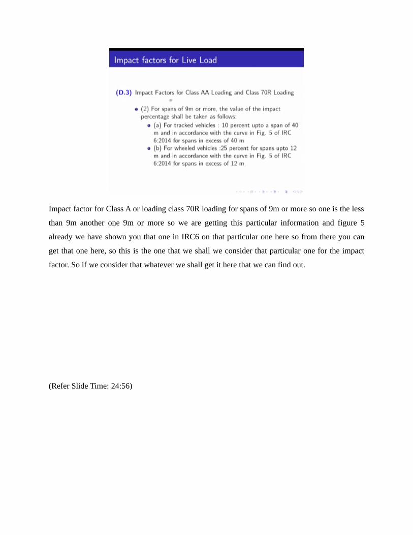
Impact factor for Class A or loading class 70R loading for spans of 9m or more so one is the less
than 9m another one 9m or more so we are getting this particular information and figure 5
already we have shown you that one in IRC6 on that particular one here so from there you can
get that one here, so this is the one that we shall we consider that particular one for the impact
factor. So if we consider that whatever we shall get it here that we can find out.
(Refer Slide Time: 24:56)

The impact factor will be equal to 10+15/9 -5 x 9/5.9 the 9m that is the one 5.9m is the thick
span which we are getting for 21.625% and so this one 5.69m obviously less than 5.9m also that
particular one also you can consider here, this is the one I am talking this particular one here that
not the full length we are getting that particular one here that one your load is coming less than
5.9 m that particular one that is inside the bridge that particular one.
So intensity up loading will be equal to 1.21625x700 kilo Newton I have converted to that 5.69
in the longitudinal direction 7.324 already we have calculated for both the wheel which comes as
5.69x7.324=20.429kN/m2 so this is the one that intensity we are getting this particular
information we have got it here, so what we can do it here than in the slab it is like this, so this is
5.9 and this one we are getting it here 5.69 so this 5.69 I am talking this 5.69 here so live load
bending moment equal to 20.429x5.69/2x5.9/2-20.429x5.9/2x5.9/4 this is equal to 82.564
kNm/m width.
So this is the one live load bending moment, so we have got this particular one 82.564 and then
with that we shall add the bending moment of.
(Refer Slide Time: 29:21)

So total bending moment equal to 57.611 which is coming from the dead load plus 82.564 which
is equal to 140.175 kNm/m width, so when we have got this particular one here then with this
bending moment we shall check the depth, so we have now crossed the first hurdle that yes, this
much bending moment will come in the beam and that one here it is coming like this traffic
direction this particular one here and I can take a jeep I am taking one this is the area, and this is
how much 1m that 1m width that particular one I am talking this particular one here.
So that means I have to design this slab or beam whatever you call then we have to check that
460mm that overall that we have considered whether that can resist this movement or not. Now
the first thing we are considering here we shall check with the working stress method this
particular one here then we shall create with the limit state methods other two methods that we
shall check and we shall find out that okay, so that we shall do it in the next lecture, thank you
very much.