nps/003/010 code of practice 4.0 october 2018 nps/003/010 ...dedicated for specific load types i.e....
TRANSCRIPT
Document reference:- NPS/003/010 Document Type:- Code of Practice
Version:- 4.0 Date of Issue:- October 2018 Page:- 1 of 23
Information Classification – PUBLIC
CAUTION! - This document may be out of date if printed
NPS/003/010 - Technical Specification for 400V PSC-Assemblies (LVAC Boards) utilised in Major Substations
1. Purpose
This document is the technical specification for 400V LVAC PSC-Assemblies for use in major substations on Northern Powergrid’s distribution network.
This document supersedes the following documents, all copies of which should be destroyed.
Reference Version Date Title
NPS/003/010 3.0 Dec 2013 Technical Specification for 400V Assemblies (LVAC Boards) utilised in Major Substations
2. Scope
This specification covers the technical requirements for 400V AC PSC-Assemblies (LVAC Boards) used to control LV
auxiliary supplies in Major substations on Northern Powergrid’s distribution network. It has been created using IEC/TR 61439-0 as a basis in accordance with best practice.
Specific requirements are listed in the included Appendices and in the drawings referenced. The following appendices form part of this technical specification: Appendix 1 - Addendum to Supplier Requirements regarding verification, delivery and handling
Appendix 2- Table C.1 user requirements from IEC/TR 61439-0 and cross referenced to BS EN 61439 parts 1 & 2
Appendix 3 – Additional General Technical requirements.
Appendix 4 – Self Certification Conformance declaration to be completed by the supplier.
Appendix 5 – Technical Information Check List
Appendix 6 - Primary Substation Indoor LVAC Assembly
Appendix 7 - Grid Supply Point Indoor LVAC Assembly (1 or 2 Incomers)
Appendix 8 – Generation Substation Indoor LVAC Assembly Type 1
Appendix 9 - Generation Substation Indoor LVAC Assembly Type 2
Appendix 10 - Generation Substation Indoor LVAC Assembly Type 3

Document reference:- NPS/003/010 Document Type:- Code of Practice
Version:- 4.0 Date of Issue:- October 2018 Page:- 2 of 23
Information Classification – PUBLIC
CAUTION! - This document may be out of date if printed
Contents 2.1.
1. Purpose ................................................................................................................................................................................. 1 2. Scope ..................................................................................................................................................................................... 1
2.1. Contents ....................................................................................................................................................................... 2
3. Technical Requirements........................................................................................................................................................ 3 3.1. General ......................................................................................................................................................................... 3
3.1.1. Primary Substation Indoor LVAC Assembly (Appendix 6) ............................................................................................ 3
3.1.2. Grid Supply Point Substation Indoor LVAC Assembly (Appendix 7) ............................................................................. 3
3.1.3. Generation Substation Indoor LVAC Assemblies Types 1 – 3 (Appendices 8-10) ........................................................ 3
3.1.3.1. Generation Substation Indoor LVAC Assembly – Type 1 (Appendix 8) .................................................................... 3
3.1.3.2. Generation Substation Indoor LVAC Assembly – Type 2 (Appendix 9) .................................................................... 4
3.1.3.3. Generation Indoor LVAC Assembly – Type 3 (Appendix 10) .................................................................................... 4
3.2. Indoor Assemblies ........................................................................................................................................................ 4
3.3. Outdoor Assemblies ..................................................................................................................................................... 5
4. References ............................................................................................................................................................................ 6 4.1. External Documentation .............................................................................................................................................. 6
4.2. Internal Documentation ............................................................................................................................................... 6
4.3. Amendments from Previous Version ........................................................................................................................... 6
5. Definitions ............................................................................................................................................................................. 7 6. Authority for issue ................................................................................................................................................................ 9
6.1. CDS Assurance .............................................................................................................................................................. 9
6.2. Author .......................................................................................................................................................................... 9
6.3. Technical Assurance ..................................................................................................................................................... 9
6.4. Approval ....................................................................................................................................................................... 9
6.5. Authorisation................................................................................................................................................................ 9
Appendix 1 – Addendum to Supplier Requirements ................................................................................................................... 10 Appendix 2: BS EN 61439 Specification Guidance – Indoor Assemblies...................................................................................... 11 Appendix 3: Additional General Technical Requirements ........................................................................................................... 14 Appendix 4 - SELF CERTIFICATION CONFORMANCE DECLARATION ............................................................................................ 15 Appendix 5 – Technical Information Check List ........................................................................................................................... 18 Appendix 6 – PRIMARY SUBSTATION INDOOR LVAC ASSEMBLY (1 or 2 Transformers) .............................................................. 19 Appendix 7 – GRID SUPPLY POINT INDOOR LVAC ASSEMBLY (1 or 2 Incomers) ......................................................................... 20 Appendix 8 – GENERATION SUBSTATION INDOOR LVAC ASSEMBLY Type 1 ............................................................................... 21 Appendix 9 – GENERATION SUBSTATION INDOOR LVAC ASSEMBLY Type 2 ............................................................................... 22 Appendix 10 – GENERATION SUBSTATION INDOOR LVAC ASSEMBLY Type 3 ............................................................................. 23

Document reference:- NPS/003/010 Document Type:- Code of Practice
Version:- 4.0 Date of Issue:- October 2018 Page:- 3 of 23
Information Classification – PUBLIC
CAUTION! - This document may be out of date if printed
3. Technical Requirements
General 3.1.
The majority of Assemblies shall be 3 phase 400V modular construction complying with BS EN 61439 Parts 1 and 2. Internal separation shall be Form 4b (busbars, each functional unit and each set of terminals all in separate compartments). There is rare occasional need for a 230V Single Phase supplied assembly in remote Generation sites where it is not financially practical to convert an existing Single phase HV network to a three phase supply. The full details of those requirements will be confirmed on a project by project basis so are not included within this specification.
Assemblies shall be suitable for terminating PVC insulated and sheathed, armoured multicore cables in a range of sizes to match the rating of the associated circuit (120mm² copper XLPE max. on incomers) using compression type glands.
Northern Powergrid requires three standard arrangements of assembly. These are further detailed in the Appendices with the following being a general guide as to the application and use of each of the arrangements on particular sites.
3.1.1. Primary Substation Indoor LVAC Assembly (Appendix 6)
A Primary Substation Indoor LVAC Assembly is fed through two dedicated 50kVA Tank Mounted Auxiliary Transformer incomers located within the curtilage of the substation and controlled via an automatic changeover arrangement which shall include a Manual “Test” switch to force a changeover from the normal incomer to the reserve when operated. The two incomers are typically associated with each of the Primary Transformers. There are a total of six outgoing supplies from the LVAC board out of which two are dedicated to each of the Primary Transformer Marshalling Kiosks and four outgoings supplies are dedicated to specific load types i.e. Substation Equipment, Heating, Lighting, Battery Charger etc. of the primary substation. The details of the circuits associated with these distribution boards are included in Appendix 6.
3.1.2. Grid Supply Point Substation Indoor LVAC Assembly (Appendix 7)
A typical Grid Supply Point Substation Indoor LVAC Assembly is fed through two 200kVA Earthing Auxiliary Transformer (EAT) incomers located within the curtilage of the substation and controlled via an automatic changeover arrangement which shall include a Manual “Test” switch to force a changeover from the normal incomer to the reserve when operated. The two incomers are typically associated with the EAT of the Grid Transformers. There are a total of six distribution boards out of which two are dedicated to supplying power to the respective Grid Transformer Marshalling Kiosks and four outgoing supplies are dedicated to specific load types i.e. Substation Equipment, Heating, Lighting, Battery Charger etc. of the Grid Supply Point Substation. The details of the circuits associated with these distribution boards are included in Appendix 7.
3.1.3. Generation Substation Indoor LVAC Assemblies Types 1 – 3 (Appendices 8-10) Generation Substation Assemblies are categorized into three different types.
3.1.3.1. Generation Substation Indoor LVAC Assembly – Type 1 (Appendix 8)
A Generation LVAC Board - Type 1 is typically associated with 33kV / 66kV Generation Substations fed via two incomers and controlled via an automatic changeover arrangement which shall include a Manual “Test” switch to force a changeover from the normal incomer to the reserve when operated. One of the incomers is sourced from the NPg network (via PMT or a UDE), and the other is sourced from a metered customer supply with the LVAC board normally being fed from the customer’s side. The maximum import power of this type of board is limited to 50kVA. There are a total of four outgoing supplies from this type of LVAC Assembly; one of which is dedicated to supplying the customer in an event of loss of power at their end (only to be used for their essentials i.e. charging batteries,

Document reference:- NPS/003/010 Document Type:- Code of Practice
Version:- 4.0 Date of Issue:- October 2018 Page:- 4 of 23
Information Classification – PUBLIC
CAUTION! - This document may be out of date if printed
emergency lighting), and three others dedicated for specific load types i.e. Substation Equipment, Heating, Lighting, Battery Charger etc. of the Generation Substation. The details of circuits associated with these distribution boards are included in Appendix 8.
3.1.3.2. Generation Substation Indoor LVAC Assembly – Type 2 (Appendix 9)
A Generation LVAC Board - Type 2 is typically associated with a 132kV Generation Substation (with Grid Transformer) fed via three incomers controlled via two automatic changeover arrangements which shall include a Manual “Test” switches to force a changeover from the normal incomer and each subsequent reserve when operated. One of the incomers is sourced from the NPg network (via PMT or a UDE). A second is sourced from a metered customer supply with the LVAC board normally being fed from the customer’s side on to a changeover terminal. The third incomer is sourced from the EAT associated with the Grid Transformer at the substation. The maximum import power of this type of board is limited to 200kVA. There are a total of five outgoing supplies from this type of LVAC board out of which, one is dedicated to supplying the customer in an event of loss of power at their end (only to be used for their essentials i.e. charging batteries, emergency lighting) and other four are dedicated for specific load types i.e. Grid Transformer Marshalling Kiosk, Substation Equipment, Heating, Lighting, Battery Charger etc. of the Generation Substation. The details of circuits associated with these distribution boards are included in Appendix 9.
3.1.3.3. Generation Indoor LVAC Assembly – Type 3 (Appendix 10)
A Generation LVAC Board – Type 3 is typically associated with a 132kV Generation Substation (without Grid Transformer) and fed via two incomers controlled via an automatic changeover arrangement which shall include a Manual “Test” switches to force a changeover from the normal incomer and each subsequent reserve when operated One of the incomers is sourced from the NPg network (via PMT or a UDE) and the other is sourced from a metered customer supply with the LVAC board normally being fed from the customer’s side. The maximum import power of this type of board is limited to 200kVA. There are a total of four outgoing supplies from this type of LVAC board out of which one is dedicated to supplying the customer in an event of loss of power at their end (only to be used for their essentials i.e. charging batteries, emergency lighting), and three other outgoing supplies are dedicated for specific load types i.e. Substation Equipment, Heating, Lighting, Battery Charger etc. of the Generation Substation. The details of circuits associated with these distribution boards are included in Appendix 10.
Indoor Assemblies 3.2.
Indoor assemblies shall typically comprise two or three incoming units, two outgoing units and up to four
distribution boards. The functional sources and destination (load) of these will be as follows:
Arrangement Type Primary Substation
Grid Supply Point
Substation
Generation Substation
Type 1
Generation Substation
Type 2
Generation Substation
Type 3 Source /
Destination
Incomer 1 Auxiliary TX 1 Auxiliary TX 1 Customer Aux Supply 1
Customer Aux Supply 1
Customer Aux Supply 1
Incomer 2 Auxiliary TX 2 Auxiliary TX 2 NPg Aux Supply
NPg Aux Supply 1
NPg Aux Supply 1
Incomer 3 N/A N/A N/A NPg Aux Supply 2
N/A
Generator Incomer Generator 1 N/A N/A N/A N/A
Outgoing 1 TX 1 Marshalling
Grid TX 1 Marshalling
Customer Supply CB in series with Customer
Supply Fuse
Customer Supply CB in series with Customer
Supply Fuse
Customer Supply CB in series with Customer
Supply Fuse
Outgoing 2 TX 2 MK Supply
Grid TX 2 MK Supply
N/A Grid Tx MK Supply
N/A
Dist Board 1 Heating Heating Heating, Heating, Heating,

Document reference:- NPS/003/010 Document Type:- Code of Practice
Version:- 4.0 Date of Issue:- October 2018 Page:- 5 of 23
Information Classification – PUBLIC
CAUTION! - This document may be out of date if printed
Lighting & Power
Lighting & Power
Lighting & Power
Dist. Board 2 Lighting & Power
Lighting & Power
Substation Equipment
Substation Equipment
Substation Equipment
Dist. Board 3 Substation Auxiliaries (inc
230/110 Tx)
Substation Auxiliaries (inc
230/110 Tx)
110VAC Supplies
110VAC Supplies
110VAC Supplies
Dist Board 4 110VAC Supplies
110VAC Supplies
N/A N/A N/A
NPg Drawings C1017575 C1083403 C1083404 C1083405 C1083406
Where specified, there shall be a mechanical changeover switch between Incomer 1 and the Generator incomer so that a generator can be connected to maintain supplies in the event of loss of normal supplies. An auto-changeover shall be provided between Incomer 1 and Incomer 2 to ensure supplies are maintained to all outgoing circuits. The auto-changeover is biased to Incomer 1 which is usually taken from Transformer or Supply 1 and shall include a Manual “Test” switches to force a changeover from the normal incomer to the reserve when operated. At substations with three transformers there shall be an additional incoming way and a second auto changeover facility with manual Test switch.
The 230/110V transformer shall be rated 2kVA and centre earth tapped on the LV side 230/55-0-55V. This shall supply Distribution Board 3 OR 4 – 110V supplies depending on type of site. MCBs shall comply with BS EN 60898-1 and be rated and tested as a point of isolation. Instantaneous tripping shall be Type C (7.5 x MCB rating) and Type D (12 x MCB rating).
Outdoor Assemblies 3.3.
Outdoor assemblies will only be required in exceptional circumstances (when the distance between the auxiliary transformer and the indoor assembly is greater than 100m.) In these situations the specific clauses and requirements resulting from the change of environment will be established and confirmed.

Document reference:- NPS/003/010 Document Type:- Code of Practice
Version:- 4.0 Date of Issue:- October 2018 Page:- 6 of 23
Information Classification – PUBLIC
CAUTION! - This document may be out of date if printed
4. References
External Documentation 4.1.
The products described within this specification shall comply with all current versions of the relevant International Standards, British Standard Specifications and all relevant Energy Networks Association Technical Specifications (ENATS) current at the time of supply in this respect the following documents are particularly relevant.
Reference Title
IEC/TR 61439-0:2013 Low voltage switchgear and controlgear assemblies Part 0: Guidance to specifying assemblies
BS EN 61439-1:2011 Low voltage switchgear and controlgear assemblies: Part 1: General rules
BS EN 61439-2:2011
Low voltage switchgear and controlgear assemblies: Part 2: Power switchgear and controlgear assemblies
BS EN 60529:1992+A2:2013 Degree of protection provided by enclosures (IP Code)
BS EN 60898-1:2003+A13:2012 Circuit Breakers for overcurrent protection for households and similar Installations
BS EN 60947-2:2017 Low-voltage switchgear and controlgear Part 2: Circuit-breakers
BS HD 60269-2 : 2010, BS 88-2 : 2010
Low-voltage fuses. Supplementary requirements for fuses for use by authorized persons (fuses mainly for industrial application). Examples of standardized systems of fuses A to J
Internal Documentation 4.2.
Amendments from Previous Version 4.3.
Reference Title
C1017575 Drawing – Plant Standard Indoor LVAC Switchboard for Primary Substations
C1083403 Drawing – Plant Standard Indoor LVAC Switchboard for Grid Supply Point Substations
C1083404 Drawing – Plant Standard Indoor LVAC Switchboard for Generation Substations Type 1
C1083405 Drawing – Plant Standard Indoor LVAC Switchboard for Generation Substations Type 2
C1083406 Drawing – Plant Standard Indoor LVAC Switchboard for Generation Substations Type 3
Clause Subject Amendments
All Format updated to current standard
2.1 Contents Table inserted
3.1 General Requirements Additional clarification / expansion on types with creation of sub sections.
3.2 Indoor Assemblies Added Table for clarification

Document reference:- NPS/003/010 Document Type:- Code of Practice
Version:- 4.0 Date of Issue:- October 2018 Page:- 7 of 23
Information Classification – PUBLIC
CAUTION! - This document may be out of date if printed
5. Definitions
3.3 Outdoor Assemblies Added text.
4.1 References Text added and table updated
4.2 Internal Documentation Expanded table to reflect added drawings and Arrangement drawing has been made obsolete
4.3 Amendments Table Insert of new table
5 Definitions Updated and expanded
Appendix 1 Addendum to Suppliers Requirements
New added content. Old Appendix 1 now appendix 2
Appendix 2 BS EN 61439 Specification Guidance – Indoor Assemblies
Updated to current version
Appendix 3 Additional General Technical Requirements
Old Appendix 2 – Details expanded and updated
Appendix 4 Self-Certification Conformance Declaration
Old Appendix 3 – Format and details updated
Appendix 5 Technical Information Check List
New Added
Appendix 6 PRIMAR SUBSTATION INDOOR LVAC ASSEMBLY (1 or 2 Transformers)
Old Appendix 5 – Title updated
Appendices 7-10
Assembly Details Tables New tables added
Reference Title
PSC-Assembly Low-voltage switchgear and controlgear assembly used to distribute and control energy for all types of loads, intended for industrial, commercial and similar applications where operation by ordinary persons is not intended (formerly an Assembly / LVAC Board).
Major Substation A major substation forms part of the Primary Distribution System. This includes typically, but not exclusively, Grid Supply point (GSP), Supply point (SP), Primary Substation, EHV switching station, Large EHV / HV* load customers and Large EHV/HV* generation substations. * HV connected means directly to the HV busbar at a primary substation, and does not include any HV load/generation customer connected to the Secondary Distribution System.
Grid Supply Point A Grid Supply Point, or GSP, is a Systems Connection Point at which the Transmission System is connected to a Distribution System. The substation will transform an incoming voltage (typically 400 or 275kV) to lower voltages used on the Distribution System (typically 132 or 66kV).
Supply Point Substation to transform 132kV voltage to EHV.
Primary Substation Substation to transform 132kV or EHV voltage to HV. Part of the Primary Distribution System.

Document reference:- NPS/003/010 Document Type:- Code of Practice
Version:- 4.0 Date of Issue:- October 2018 Page:- 8 of 23
Information Classification – PUBLIC
CAUTION! - This document may be out of date if printed
A Primary Substation is a Connection Point at which the Primary Distribution System is connected to the Secondary Distribution System.
EHV Extra High Voltage. All assets with a nominal operating voltage of 33kV or 66kV, including the 33kV or 66kV circuit breaker(s) at a 400 or 275kV/EHV, 132kV/EHV or EHV/HV substation.
HV High Voltage. All assets with a nominal operating voltage between 1kV and 22kV, including the HV circuit breaker at EHV to HV substations and HV switchgear and HV to LV transformer at HV substations.
Circuit Breaker Air Circuit Breaker (ACB) or Mould Case Circuit Breaker (MCCB)
PMT Pole Mounted Transformer
UDE Unit Distribution Equipment
MK Marshalling Kiosk

Document reference:- NPS/003/010 Document Type:- Code of Practice
Version:- 4.0 Date of Issue:- October 2018 Page:- 9 of 23
Information Classification – PUBLIC
CAUTION! - This document may be out of date if printed
6. Authority for issue
CDS Assurance 6.1.
I sign to confirm that I have completed and checked this document and I am satisfied with its content and submit it for approval and authorisation.
Sign Date
Andy Leggett CDS Administrator Andy Leggett 26/09/2018
Author 6.2.
I sign to confirm that I have completed and checked this document and I am satisfied with its content and submit it for approval and authorisation.
Review Period - This document should be reviewed within the following time period.
Standard CDS review of 3 years? Non Standard Review Period & Reason
No Period: 5 Years Reason: Update will be dictated by contract renewal date or any significant changes in the specification or documents referenced
Should this document be displayed on the Northern Powergrid external website? No
Sign Date
Alan MacDonald Policy & Standards Engineer Alan MacDonald 26/09/2018
Technical Assurance 6.3.
I sign to confirm that I am satisfied with all aspects of the content and preparation of this document and submit it for approval and authorisation.
Sign Date
Sunil Shrestha Design and Specification Engineer Sunil Shrestha 26/09/2018
Joe Helm Senior Policy & Standards Engineer
Joe Helm 26/09/2018
Ray Puryer Primary Engineering Projects Zone Team Leader
Ray Puryer 27/09/2018
Approval 6.4.
Approval is granted for publication of this document.
Sign Date
David Gazda Policy & Standards Manager David Gazda 15/10/2018
Authorisation 6.5.
Authorisation is granted for publication of this document.
Sign Date
Greg Farrell Head of System Strategy Greg Farrell 24/10/2018

Document reference:- NPS/003/010 Document Type:- Code of Practice
Version:- 4.0 Date of Issue:- October 2018 Page:- 10 of 23
Information Classification – PUBLIC
CAUTION! - This document may be out of date if printed
Appendix 1 – Addendum to Supplier Requirements
Items to be supplied with each and every ASSEMBLY Copies of routine verification procedures and results:
These shall include a listing of the results of micro-ohmmeter tests of the resistance between the incoming transformer or generator side, busbars and each of the outgoing contacts. This test shall be done at the end of all production procedures, but before any over voltage tests. One copy to be supplied as a weatherproof, durable, hard copy attached to the unit being supplied and one copy to be supplied electronically.
Handling Instructions and delivery:
A weatherproof, durable, permanently fixed label with lifting/slinging arrangements with and without packaging shall be attached to the ASSEMBLY. This label shall include, at least: gross weight, attachment/lifting points, recommended slinging arrangements and indication of centre of gravity. If appropriate this label shall be repeated on the outside of the packaging. Deliveries shall be made direct to substation sites within the Northern Powergrid area. Proposals for the off-loading of the assembly on site shall be supplied. It should be noted that risk assessments and method statements will be required prior to delivery and that if a crane delivery is proposed, trained operators and slingers will be required who should provide proof of competence (CITB certificates etc).

Document reference:- NPS/003/010 Document Type:- Code of Practice
Version:- 4.0 Date of Issue:- October 2018 Page:- 11 of 23
Information Classification – PUBLIC
CAUTION! - This document may be out of date if printed
Appendix 2: BS EN 61439 Specification Guidance – Indoor Assemblies
Characteristics IEC/TR 61439-0 Annex C.1
BS EN 61439-1:2011 / BS EN 61429-2:2011
User Requirements
Electrical System 5
Earthing system 5.2 5.6, 8.4.3.1, 8.4.3.2.3, 8.6.2, 10.5, 11.4
TN-S
Nominal Voltage (V) 5.3 3.8.9.1, 5.2.1, 8.5.3 400V +10%, -6% 3 phase
Transient overvoltages 5.4, 5.5 5.2.4, 8.5.3, 9.1, Annex G
Cat IV
Temporary overvoltages 5.5 9.1 As above
Rated frequency fn (Hz) 5.6 3.8.12, 5.5, 8.5.3, 10.10.2.3, 10.11.5.4
50Hz
Additional onsite testing requirements: wiring, operational performances and function
5.7 11.10 Not required
Short-circuit withstand capability 6
Prospective short-circuit current at supply terminals Icp (kA)
6.2 3.8.7 35kA for 1 sec
Prospective short-circuit current on the neutral
6.3 10.11.5.3.5 60%
Prospective short-circuit current in the protection
6.4 10.11.5.6 60%
SCPD in the incoming functional unit
6.5 9.3.2 Not required
Co-ordination of short-circuit protective devices including external short-circuit protective device details
6.6 9.3.4 Supplier to determine
Data associated with loads likely to contribute to the short-circuit current
6.7 9.3.2 Not applicable
Protection of persons against electric shock in accordance with IEC 60364-4-41
7
Protection against electric shock – basic protection
7.2 8.4.2 Barriers or enclosures
Protection against electric shock – fault protection
7.3 8.4.3 To comply with 7.3.2
Installation environment 8
Location type 8.2 3.5, 8.1.4, 8.2 Indoor
Protection against ingress of solid foreign bodies and ingress of water
8.3 8.2.2, 8.2.3 IP41D
Protection after removal of withdrawable part
8.3 8.2.101 Not applicable
External mechanical impact (IK) 8.4 8.2.1, 10.2.6 Not applicable
Resistance to UV radiation 8.5 10.2.4 Not applicable
Resistance to corrosion
8.6 10.2.2 Severity A
Ambient air temperature – Lower limit
8.7 7.1.1 -5° C

Document reference:- NPS/003/010 Document Type:- Code of Practice
Version:- 4.0 Date of Issue:- October 2018 Page:- 12 of 23
Information Classification – PUBLIC
CAUTION! - This document may be out of date if printed
Ambient air temperature – Upper limit
8.7 7.1.1 40°C
Ambient air temperature – Daily average maximum
8.7 7.1.1, 9.2 35° C
Maximum relative humidity 8.8 7.1.2 50% at 40°C 90% at 20°C
Pollution degree 8.9 7.1.3 Pollution degree 3
Altitude 8.10 7.1.4 Not applicable
EMC environment 8.11 9.4, 10.12, Annex J Environment A
Special service conditions 8.12 7.2, 8.5.4, 9.3.3, Table 7
None
Installation method 9
Type 9.2 3.3, 5.6 Mounted over a cable trench and bolted to the wall
Portability 9.3 3.5 Stationary
Maximum overall dimensions and weight
9.4 5.6, 6.2.1 Assemblies shall be sized and constructed to satisfy the performance requirements specified, but within the minimum size and weight as possible.
External conductor type 9.5 8.8 Cable
Direction of external conductors 9.6 8.8 Bottom
External conductor material 9.7 8.8 Copper
External phase conductor, cross sections and terminations
9.8 8.8 4 core - 95mm² OR 120mm² copper
External PE, N, PEN conductor cross sections, and terminations
9.9 8.8 Neutral same size as phases
Special terminal identification requirements
9.10 8.8 None
Storage and handling 10
Maximum dimensions and weight of transport units
10.2 6.2.2, 10.2.5 None
Methods of transport (e.g. forklift, crane)
10.3 6.2.2, 8.1.6 None
Environmental conditions different from the service conditions
10.4 7.3 None
Packing details 10.5 6.2.2 None
Operating arrangements 11
Access to manually operated devices
11.2 8.4 Authorised Person
Location of manually operated devices
11.2 8.5.5 To comply with 11.2
Isolation of load installation equipment items.
11.3 8.4.2, 8.4.3.3, 8.4.6.2 Separate compartment for each functional unit
Maintenance and upgrade capabilities
12
Requirements related to accessibility for inspection and similar operations
12 8.4.6.2.2 Not applicable
Requirements related to accessibility for maintenance in
12.2 8.4.6.2.3 Inspection. Replacement of fuses and

Document reference:- NPS/003/010 Document Type:- Code of Practice
Version:- 4.0 Date of Issue:- October 2018 Page:- 13 of 23
Information Classification – PUBLIC
CAUTION! - This document may be out of date if printed
service by authorized persons lamps. Fault location on internal circuits and outgoing circuits.
Requirements related to accessibility for extension in service authorized persons
12.3 8.4.5.2.3 Access to isolated functional units
Requirements related to accessibility for extension in service by authorised persons
12.4 8.4.6.2.4 Not required
Method of functional units connection
12.6 8.5.1, 8.5.2 F - fixed connections
Protection against direct contact with hazardous live internal parts during maintenance or upgrade
12.5 8.4 Protection required to prevent access to live parts
Gangways 12.7 8.4.6.2.101 Not required
Method of functional unit’s connection NOTE This refers to the capability of
removal and re-insertion of functional units.
8.5.101 F - fixed connections
Form of separation 12.8 Table B.1 8.101 Form 4b
Capability to test individual operation of the auxiliary circuits relating to specified circuits while the functional unit is isolated.
12.2 3.1.102, 3.2.102, 3.2.103, 8.5.101, Table 103
Yes
Current carrying capability 13
Rated current of the assembly InA (A)
13.2 3.8.9.1, 5.3, 8.4.3.2.3, 8.5.3, 8.8, 10.10.2, 10.10.3, 10.11.5, Annex E
Up to 300A depending on arrangement
Rated current of circuits InC (A) 13.3 5.3.2 See drawings applicable to each type
Rated diversity factor 13.4 5.3.3, 10.10.2.3, Annex E
No diversity
Ratio of cross-section of the neutral conductor to phase conductors
13.5 8.6.1 100%

Document reference:- NPS/003/010 Document Type:- Code of Practice
Version:- 4.0 Date of Issue:- October 2018 Page:- 14 of 23
Information Classification – PUBLIC
CAUTION! - This document may be out of date if printed
Appendix 3: Additional General Technical Requirements
Substation LVAC Assembly Specification
Unit Requirement
Fuse Specification BS HD 60269-2 : 2010, BS 88-2 : 2010
Miniature Circuit Breaker Specification
BS EN 60898 or 60947-1 as appropriate,. But shall be suitable for isolation
Contactors and timers Suitable for 300V overvoltage
Gland plate: Min height above ground level.
mm 450
Space below gland plate Must be enclosed and vermin proof
Access: Installation Front
Access: Operation Front
Access: Maintenance Front
Locking Arrangements Isolators/switch fuses shall be suitable for locking-off with padlocks with a 5mm diameter shackle in the ON and OFF position.
Door stays All access covers must be fitted with door stays
Testing lamp facility Incoming terminals should have access for testing without the need to remove covers (suitable for use typically with Drummond or Cyclim test lamps).
The typical requirements may need to be altered for specific project based applications by Primary Engineering Projects. A3.1 Mounting
LVAC assemblies shall be suitable for mounting across two parallel flange channels (PFC) over a concrete cable trench for bottom cable entry. Indoor boards shall be suitable for mounting against and fixing to a wall.
A3.2 Drawings
The following drawings showing typical arrangements for the circuits on the assembly shall be provided separately as their size restricts usable inclusion within this specification.
C1017575 Plant Standard Indoor LVAC Switchboard for Primary Substations C1083403 Plant Standard Indoor LVAC Switchboard for Grid Supply Point Substations C1083404 Plant Standard Indoor LVAC Switchboard for Generation Substations Type 1 C1083405 Plant Standard Indoor LVAC Switchboard for Generation Substations Type 2 C1083406 Plant Standard Indoor LVAC Switchboard for Generation Substations Type 3

Document reference:- NPS/003/010 Document Type:- Code of Practice
Version:- 4.0 Date of Issue:- October 2018 Page:- 10 of 14
Information Classification – PUBLIC
CAUTION! - This document may be out of date if printed
Appendix 4 - SELF CERTIFICATION CONFORMANCE DECLARATION LVAC Assemblies shall comply with the latest issues of the relevant national and international standards, including, IEC/TR 61439-0:2013 and BS EN 61439 Parts 1 & 2.. Additionally this technical specification is intended to amplify and/or clarify the requirements of elements of these Standards. This self-declaration sheet identifies the clauses of the aforementioned standards relevant to Fuseboards, Fusepillars, Fusecabinets and Circuit Breakers (CB’s) for use on Northern Powergrid distribution network. The manufacturer shall declare conformance or otherwise, clause by clause, using the following levels of conformance declaration codes Conformance declaration codes N/A = Clause is not applicable/ appropriate to the product Cs1 = The product conforms fully with the requirements of this clause Cs2 = The product conforms partially with the requirements of this clause Cs3 = The product does not conform to the requirements of this clause Cs4 = The product does not currently conform to the requirements of this clause, but
the manufacturer proposes to modify and test the product in order to conform.
Manufacturer: Product Reference: Related ASSEMBLY type(s): Name and position/role (block capitals): Signature & Date: NOTE: A separate self-declaration shall be completed for each item or variant submitted, OR the products can be grouped together and a group declaration made for each group IF every self-declaration states clearly the range of products to which it applies.
Instructions for Completion • When Cs1 code is entered:
(i) State the reference of test reports, etc. that support this declaration AND
(ii) A summary of the compliance. • When any other code is entered: state the reference of the
test report(s), etc. that support this declaration AND a summary of the reason for non-conformance.
• Prefix each remark with the relevant ‘BS EN’ ‘IEC’ or
‘ENATS’ as appropriate to indicate which specification the comment is made against.

Document reference:- NPS/003/010 Document Type:- Code of Practice
Version:- 4.0 Date of Issue:- October 2018 Page:- 10 of 14
Information Classification – PUBLIC
CAUTION! - This document may be out of date if printed
Self-certificate declaration of conformance to NPS/003/010 – Technical Specification for 400V Assemblies (LVAC Boards) utilised in Major Substations
Item Clause / Requirements Conformance Code
Remarks / Comments
Supply Voltage 400v +10% -6% / 230v +10% -6%
No of Phases 3 (Single Phase in remote locations where existing networks are not 3 Phase) State.
Frequency 50 Hz
Internal Separation Form 4b
Incomers: Fuse Switch / ACB 100A / 300A
Outgoing Circuits: Fuse Switch / ACB
63A
Busbar Normal Current Rating Up to 300A, Depending on LVAC Board Type as Specified in Appendix 6, 7 & 8
Fuses BS HD 60269-2 : 2010, BS 88-2 : 2010
MCB’s BS EN 60898-1 / BS EN 60947-2
Suitable for Point of Isolation & Lockable
Fault break duty or prospective current?
35kA
Rated Short Time Withstand Current.
35kA
Rated Time Duration 1 Sec
Contactors and Timers Suitable for 300V
Incomer Cable Bottom Entry
Feeder Cable Bottom Entry
Gland plate Min 450mm above Ground / Floor level
Space below the gland plate Enclosed and vermin proof. State method of enclosure.
Installation Suitable for mounting against wall
Operation From Front
Maintenance From Front

Document reference:- NPS/003/010 Document Type:- Code of Practice
Version:- 4.0 Date of Issue:- October 2018 Page:- 10 of 14
Information Classification – PUBLIC
CAUTION! - This document may be out of date if printed
Self-certificate declaration of conformance to NPS/003/010 – Technical Specification for 400V Assemblies (LVAC Boards) utilised in Major Substations
Item Clause / Requirements Conformance Code
Remarks / Comments
Incoming and outgoing isolators / switch fuses
Lockable with a padlock with a 5mm diameter shackle
Minimum Degree Protection of Enclosures: Indoor Boards.
Indoor Boards: IP41D
Door stays Required
Test lamp facilities Testing access to incoming terminals without the need to remove covers – (typically Drummond or Cyclim test lamps).
EMC requirements EMC compatible with requirements of BS EN 61439 and CE marked

Document reference:- NPS/003/010 Document Type:- Code of Practice
Version:- 4.0 Date of Issue:- October 2018 Page:- 18 of 23
Information Classification – PUBLIC
CAUTION! - This document may be out of date if printed
Appendix 5 – Technical Information Check List The Following information shall be provided by the supplier for technical review by Northern Powergrid. Additional information shall be provided if required.
Requirements Provided (Yes / No)
Full product descriptions, drawings and part/reference numbers. Including:
A general arrangement drawing detailing the depth, height and length and the position of the main components of the assembly.
A single line diagram detailing the power and control circuits
A drawing showing the detail of fixing arrangements.
Full technical details of the main components of the assembly; including manufacturer and load/fault ratings
Appendix 4 - Completed self-certification conformance declaration
Type verification evidence – copies of test certificates, reports, etc. are required to support the self-declaration in Appendix 4
Routine test Plan (sample)
Packaging/delivery information
Document reference:- NPS/003/010 Document Type:- Code of Practice
Version:- 4.0 Date of Issue:- October 2018 Page:- 19 of 23
Information Classification – PUBLIC
CAUTION! - This document may be out of date if printed
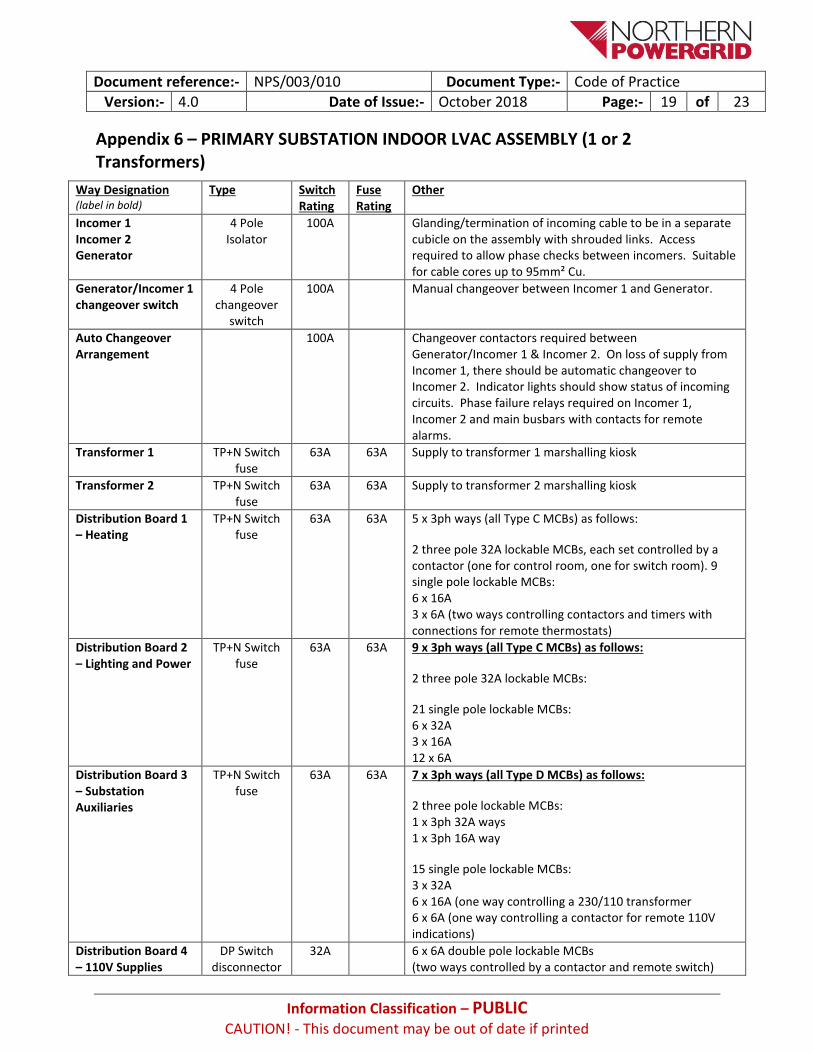
Appendix 6 – PRIMARY SUBSTATION INDOOR LVAC ASSEMBLY (1 or 2 Transformers)
Way Designation (label in bold)
Type Switch Rating
Fuse Rating
Other
Incomer 1 Incomer 2 Generator
4 Pole Isolator
100A Glanding/termination of incoming cable to be in a separate cubicle on the assembly with shrouded links. Access required to allow phase checks between incomers. Suitable for cable cores up to 95mm² Cu.
Generator/Incomer 1 changeover switch
4 Pole changeover
switch
100A Manual changeover between Incomer 1 and Generator.
Auto Changeover Arrangement
100A Changeover contactors required between Generator/Incomer 1 & Incomer 2. On loss of supply from Incomer 1, there should be automatic changeover to Incomer 2. Indicator lights should show status of incoming circuits. Phase failure relays required on Incomer 1, Incomer 2 and main busbars with contacts for remote alarms.
Transformer 1
TP+N Switch fuse
63A 63A Supply to transformer 1 marshalling kiosk
Transformer 2 TP+N Switch fuse
63A 63A Supply to transformer 2 marshalling kiosk
Distribution Board 1 – Heating
TP+N Switch fuse
63A 63A 5 x 3ph ways (all Type C MCBs) as follows:
2 three pole 32A lockable MCBs, each set controlled by a contactor (one for control room, one for switch room). 9 single pole lockable MCBs: 6 x 16A 3 x 6A (two ways controlling contactors and timers with connections for remote thermostats)
Distribution Board 2 – Lighting and Power
TP+N Switch fuse
63A 63A 9 x 3ph ways (all Type C MCBs) as follows:
2 three pole 32A lockable MCBs:
21 single pole lockable MCBs: 6 x 32A 3 x 16A 12 x 6A
Distribution Board 3 – Substation Auxiliaries
TP+N Switch fuse
63A 63A 7 x 3ph ways (all Type D MCBs) as follows:
2 three pole lockable MCBs: 1 x 3ph 32A ways 1 x 3ph 16A way
15 single pole lockable MCBs: 3 x 32A 6 x 16A (one way controlling a 230/110 transformer 6 x 6A (one way controlling a contactor for remote 110V indications)
Distribution Board 4 – 110V Supplies
DP Switch disconnector
32A 6 x 6A double pole lockable MCBs (two ways controlled by a contactor and remote switch)

Document reference:- NPS/003/010 Document Type:- Code of Practice
Version:- 4.0 Date of Issue:- October 2018 Page:- 20 of 23
Information Classification – PUBLIC
CAUTION! - This document may be out of date if printed
Appendix 7 – GRID SUPPLY POINT INDOOR LVAC ASSEMBLY (1 or 2 Incomers)
Way Designation (label in bold)
Type Switch Rating
Fuse Rating
Other
Incomer 1 : NPg Aux TX 1 Supply Incomer 2: NPg Aux TX 2 Supply
4 Pole Isolator
300A Glanding/termination of incoming cable to be in a separate cubicle on the assembly with shrouded links. Access required to allow phase checks between incomers. Suitable for cable cores up to 120mm² Cu. XLPE
Auto Changeover Arrangement
4 Pole Auto Changeover
Switch
300A Changeover contactors required between Generator/Incomer 1 & Incomer 2. On loss of supply from Incomer 1 there should be automatic changeover to Incomer 2. Indicator lights should show status of incoming circuits. Phase failure relays (PFRs) required on Incomer 1, Incomer 2 and main busbars with contacts for remote alarms.
Grid Transformer 1: Cooler and Tapchanger Supply
TP+N Switch fuse
63A 63A Supply to Grid Transformer 1 marshalling kiosk.
Grid Transformer 2: Cooler and Tapchanger Supply
TP+N Switch fuse
63A 63A Supply to Grid Transformer 2 marshalling kiosk.
Distribution Board 1 – Heating
TP+N Switch fuse
63A 63A 5 x 3ph ways (all Type C MCBs) as follows:
2 three pole 32A lockable MCBs, each set controlled by a contactor (one for control room, one for switch room).
9 single pole lockable MCBs: 6 x 16A 3 x 6A (two ways controlling contactors and timers with connections for remote thermostats)
Distribution Board 2 – Lighting and Power
TP+N Switch fuse
63A 63A 9 x 3ph ways (all Type C MCBs) as follows:
2 three pole 32A lockable MCBs:
21 single pole lockable MCBs: 6 x 32A 3 x 16A 12 x 6A
Distribution Board 3 – Substation Auxiliaries
TP+N Switch fuse
63A 63A 7 x 3ph ways (all Type D MCBs) as follows:
2 three pole lockable MCBs: 1 x 3ph 32A way 1 x 3ph 16A way
15 single pole lockable MCBs: 3 x 32A 6 x 16A (one way controlling a 230/110 2kVA Transformer) 6 x 6A (one way controlling a contactor for remote 110V indications)
Distribution Board 4 – 110V Supplies
DP Switch disconnector
32A 6 x 6A double pole lockable MCBs (two ways controlled by a contactor and remote switch)

Document reference:- NPS/003/010 Document Type:- Code of Practice
Version:- 4.0 Date of Issue:- October 2018 Page:- 21 of 23
Information Classification – PUBLIC
CAUTION! - This document may be out of date if printed
Appendix 8 – GENERATION SUBSTATION INDOOR LVAC ASSEMBLY Type 1
Way Designation (label in bold)
Type Switch Rating
Fuse Rating
Other
Incomer 1 :Customer Aux Supply Incomer 2: NPg Aux Supply
4 Pole Isolator
100A Glanding/termination of incoming cable to be in a separate cubicle on the assembly with shrouded links. Access required to allow phase checks between incomers. Suitable for cable cores up to 95mm² Cu.
Auto Changeover Arrangement
4 Pole Auto Changeover
Switch
100A Changeover contactors required between Incomer 1 & Incomer 2. On loss of supply from Incomer 1 there should be automatic changeover to Incomer 2. Indicator lights should show status of incoming circuits. Phase failure relays required on Incomer 1, Incomer 2 and main busbars with contacts for remote alarms.
Customer Supply Breaker in series with Customer Supply Fuse
Circuit Breaker plus TP+N Switch
fuse
63A
63A
Supply to Remote Customer LVAC Board
Distribution Board 1 – Heating, Lighting and Power
TP+N Switch Fuse
63A 63A 9 x 3ph ways (all Type C MCBs) as follows:
2 three pole 16A lockable MCBs, each set controlled by a contactor (one for control room, one for switch room). 21 single pole lockable MCBs: 3 x 32A 6 x 16A 10 x 6A 2 x 6A (two ways controlling contactors and timers with connections for remote thermostats)
Distribution Board 2 – Substation Equipment
TP+N Switch Fuse
63A 63A 3 x 3ph ways (all Type D MCBs) as follows:
9 single pole lockable MCBs: 6 x 16A (One way controlling a 230/110 transformer) 3 x 6A (One way controlling a contact for remote switch)
Distribution Board 3 – 110V Supplies
DP Switch disconnector
32A 6 x 6A double pole lockable MCBs (two ways controlled by a contactor and remote switch)

Document reference:- NPS/003/010 Document Type:- Code of Practice
Version:- 4.0 Date of Issue:- October 2018 Page:- 22 of 23
Information Classification – PUBLIC
CAUTION! - This document may be out of date if printed
Appendix 9 – GENERATION SUBSTATION INDOOR LVAC ASSEMBLY Type 2
Way Designation (label in bold)
Type Switch Rating
Fuse Rating
Other
Incomer 1 : Customer Auxiliary Supply Incomer 2: NPg Auxiliary Supply (PMT/UDE) Incomer 3: NPg Auxiliary Supply (EAT Supply)
4 Pole Isolator
300A
Glanding/termination of incoming cable to be in a separate cubicle on the assembly with shrouded links. Access required to allow phase checks between incomers. Suitable for cable cores up to 120 mm² Cu.
Auto Changeover Arrangement 1
300A
Changeover contactors required between Incomer 1 & Incomer 2. On loss of supply from Incomer 1 there should be automatic changeover to Incomer 2. Indicator lights should show status of incoming circuits. Phase failure relays required on Incomer 1, Incomer 2 and main busbars with contacts for remote alarms.
Auto Changeover Arrangement 2
300A
Changeover contactors required between Auto Changeover 1 & Incomer 3. On loss of output from Auto Changeover 1, there should be automatic changeover to Incomer 3. Indicator lights should show status of incoming circuits. Phase failure relays required on output of Auto Changeover 1, Incomer 3 and main busbars with contacts for remote alarms.
Customer Supply Breaker in series with Customer Supply Fuse
Circuit Breaker plus TP+N Switch
fuse
63A
63A
Supply to Remote Customer LVAC Board.
Grid Transformer Cooler and Tapchanger Supply
TP+N Switch fuse
63A 63A Supply to Grid Transformer 1 marshalling kiosk.
Distribution Board 1: Heating, Lighting and Power
TP+N Switch Fuse
63A 63A
9 x 3ph ways (all Type C MCBs) as follows:
2 three pole 16A lockable MCBs, each set controlled by a contactor (one for control room, one for switch room). 21 single pole lockable MCBs: 3 x 32A 6 x 16A 10 x 6A
2 x 6A (two ways controlling contactors and timers with connections for remote thermostats)
Distribution Board 2: Substation Equipment
TP+N Switch Fuse
63A 63A
3 x 3ph ways (all Type D MCBs) as follows:
9 single pole lockable MCBs: 6 x 16A (One way controlling a 230/110 transformer) 3 x 6A (One way controlling a contact for remote switch)
Distribution Board 3: 110V Supplies
DP Switch disconnector
32A 6 x 6A double pole lockable MCBs (two ways controlled by a contactor and remote switch)

Document reference:- NPS/003/010 Document Type:- Code of Practice
Version:- 4.0 Date of Issue:- October 2018 Page:- 23 of 23
Information Classification – PUBLIC
CAUTION! - This document may be out of date if printed
Appendix 10 – GENERATION SUBSTATION INDOOR LVAC ASSEMBLY Type 3
Way Designation (label in bold)
Type Switch Rating
Fuse Rating
Other
Incomer 1: Customer Auxiliary Supply Incomer 2: NPg Auxiliary Supply (PMT/UDE)
4 Pole Isolator
300A
Glanding/termination of incoming cable to be in a separate cubicle on the assembly with shrouded links. Access required to allow phase checks between incomers. Suitable for cable cores up to 120 mm² Cu.
Auto Changeover Arrangement
4 Pole Auto Changeover
Switch 300A
Changeover contactors required between Incomer 1 & Incomer 2. On loss of supply from Incomer 1 there should be automatic changeover to Incomer 2. Indicator lights should show status of incoming circuits. Phase failure relays required on Incomer 1, Incomer 2 and main busbars with contacts for remote alarms.
Customer Supply Breaker in series with Customer Supply Fuse
Circuit Breaker plus TP+N Switch
fuse
63A
63A
Supply to Remote Customer LVAC Board.
Distribution Board 1: Heating, Lighting and Power
TP+N Switch Fuse
63A 63A
9 x 3ph ways (all Type C MCBs) as follows:
2 three pole 16A lockable MCBs, each set controlled by a contactor (one for control room, one for switch room). 21 single pole lockable MCBs: 3 x 32A 6 x 16A 10 x 6A
2 x 6A (two ways controlling contactors and timers with connections for remote thermostats)
Distribution Board 2: Substation Equipment
TP+N Switch Fuse
63A 63A
3 x 3ph ways (all Type D MCBs) as follows:
9 single pole lockable MCBs: 6 x 16A (One way controlling a 230/110 transformer) 3 x 6A (One way controlling a contact for remote switch)
Distribution Board 3: 110V Supplies
DP Switch disconnector
32A 6 x 6A double pole lockable MCBs (two ways controlled by a contactor and remote switch)