npoess conical scanning microwave imager/ sounder (cmis) overview david kunkee june 23, 2002
TRANSCRIPT
NPOESS Conical Scanning Microwave
Imager/ Sounder (CMIS) Overview
David Kunkee
June 23, 2002

Background
• NPOESS Conical Scanning Microwave Imager Sounder (CMIS)– Continues and Improves on the Missions of SSM/I, SSMIS
– Next Generation Polar-orbiting Operational Radiometer • MISSION:
– Provide a variety of data-products: 22 Environmental Data Records (EDRs)
– An integral part of the NPOESS constellation
• Design– CMIS design was optimized with respect to an Integrated
Requirements Prioritization List (IRPL) and risk
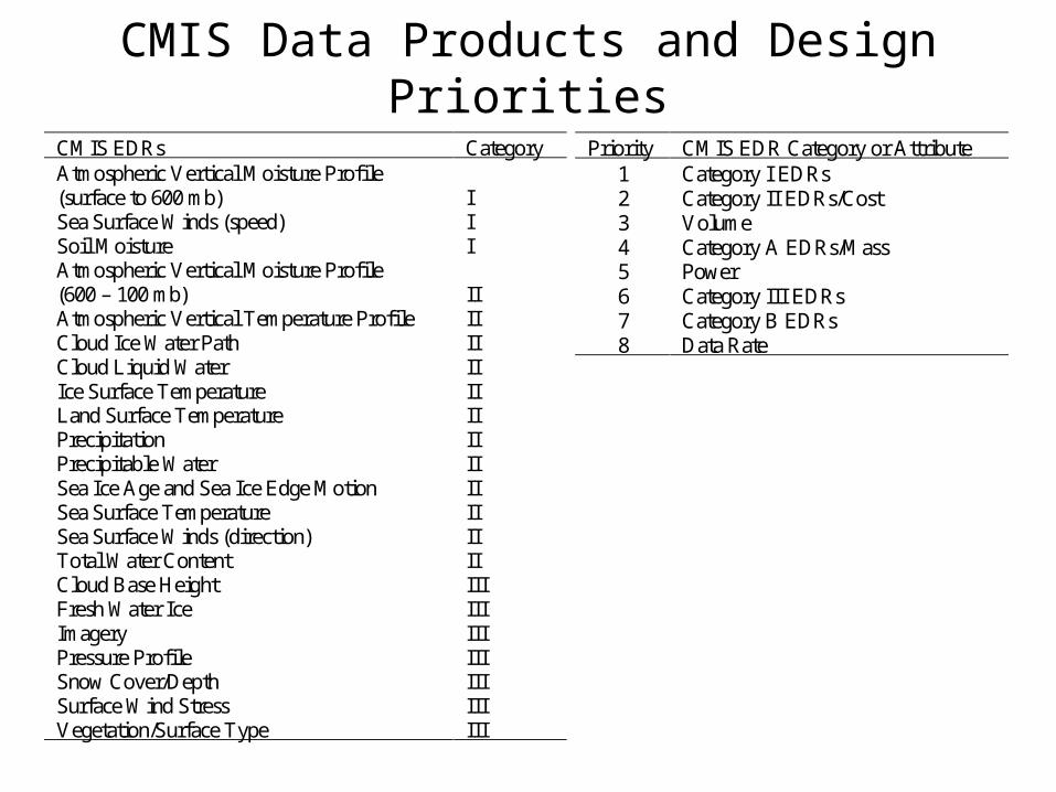
CMIS Data Products and Design Priorities
CMIS EDRs Category Atmospheric Vertical Moisture Profile (surface to 600 mb)
I
Sea Surface Winds (speed) I Soil Moisture I Atmospheric Vertical Moisture Profile (600 – 100 mb)
II
Atmospheric Vertical Temperature Profile II Cloud Ice Water Path II Cloud Liquid Water II Ice Surface Temperature II Land Surface Temperature II Precipitation II Precipitable Water II Sea Ice Age and Sea Ice Edge Motion II Sea Surface Temperature II Sea Surface Winds (direction) II Total Water Content II Cloud Base Height III Fresh Water Ice III Imagery III Pressure Profile III Snow Cover/Depth III Surface Wind Stress III Vegetation/Surface Type III
Priority CMIS EDR Category or Attribute 1 Category I EDRs 2 Category II EDRs/Cost 3 Volume 4 Category A EDRs/Mass 5 Power 6 Category III EDRs 7 Category B EDRs 8 Data Rate

CMIS Design Overview
• CMIS primary design drivers:– Cat I EDRs, Cat II EDRs and Cost
• Current CMIS Design– 77 Channels: 37 channels with 40 FFT channels
– Two main reflectors:• Low Frequencies (LF): 2.2 m
• High Frequencies (HF): 0.5 X 0.7 m
– Two feedhorn clusters• LF cluster: 12 feedhorns, 6 – 89 GHz
• HF cluster: 4 feedhorns, 166 and 183 GHz
– >0.9 reliability after 7 years on orbit + 8 years storage• Substantial redundancy
– 257 kg mass; 280 kb/s data rate; 291 W orbital average power
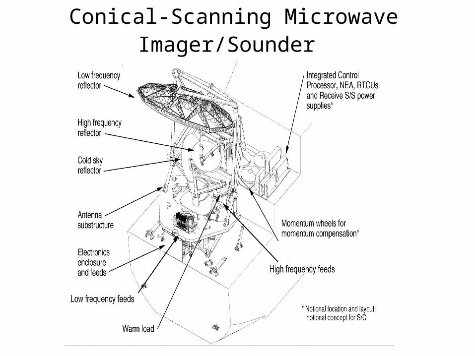
Conical-Scanning Microwave Imager/Sounder
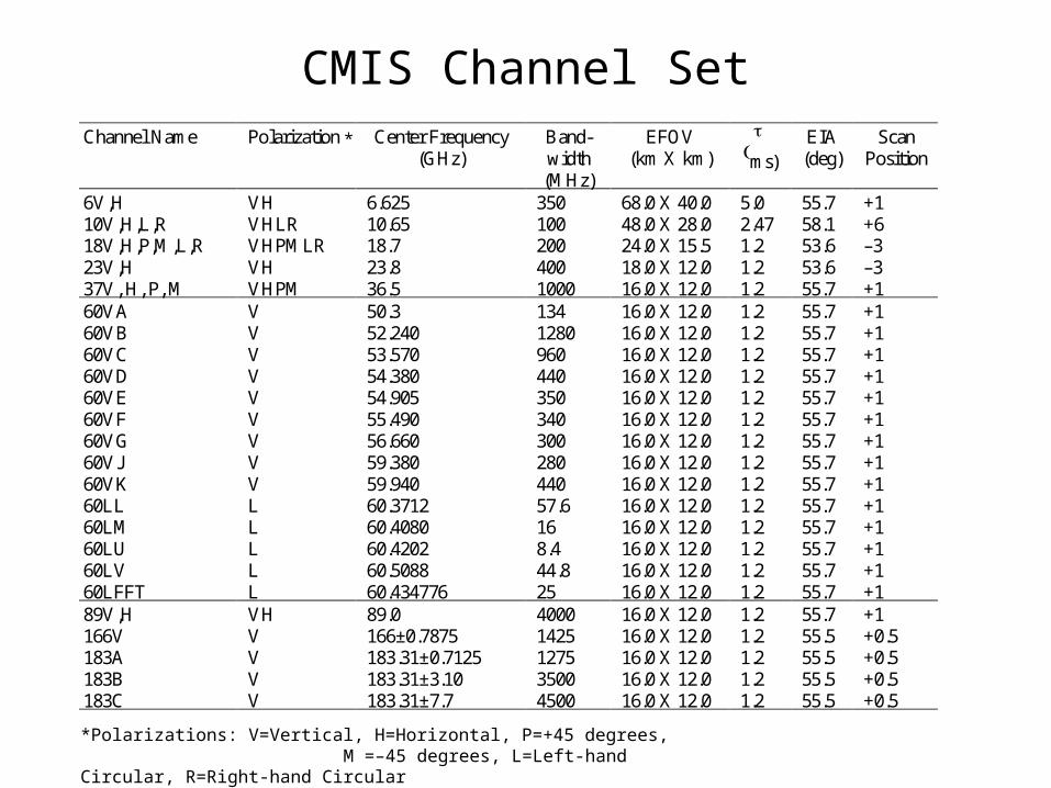
CMIS Channel Set Channel Name Polarization Center Frequency
(GHz) Band-width (MHz)
EFOV (km X km)
ms)
EIA (deg)
Scan Position
6V,H VH 6.625 350 68.0 X 40.0 5.0 55.7 +1 10V,H,L,R VHLR 10.65 100 48.0 X 28.0 2.47 58.1 +6 18V,H,P,M,L,R VHPMLR 18.7 200 24.0 X 15.5 1.2 53.6 –3 23V,H VH 23.8 400 18.0 X 12.0 1.2 53.6 –3 37V, H, P, M VHPM 36.5 1000 16.0 X 12.0 1.2 55.7 +1 60VA V 50.3 134 16.0 X 12.0 1.2 55.7 +1 60VB V 52.240 1280 16.0 X 12.0 1.2 55.7 +1 60VC V 53.570 960 16.0 X 12.0 1.2 55.7 +1 60VD V 54.380 440 16.0 X 12.0 1.2 55.7 +1 60VE V 54.905 350 16.0 X 12.0 1.2 55.7 +1 60VF V 55.490 340 16.0 X 12.0 1.2 55.7 +1 60VG V 56.660 300 16.0 X 12.0 1.2 55.7 +1 60VJ V 59.380 280 16.0 X 12.0 1.2 55.7 +1 60VK V 59.940 440 16.0 X 12.0 1.2 55.7 +1 60LL L 60.3712 57.6 16.0 X 12.0 1.2 55.7 +1 60LM L 60.4080 16 16.0 X 12.0 1.2 55.7 +1 60LU L 60.4202 8.4 16.0 X 12.0 1.2 55.7 +1 60LV L 60.5088 44.8 16.0 X 12.0 1.2 55.7 +1 60LFFT L 60.434776 25 16.0 X 12.0 1.2 55.7 +1 89V,H VH 89.0 4000 16.0 X 12.0 1.2 55.7 +1 166V V 166±0.7875 1425 16.0 X 12.0 1.2 55.5 +0.5 183A V 183.31±0.7125 1275 16.0 X 12.0 1.2 55.5 +0.5 183B V 183.31±3.10 3500 16.0 X 12.0 1.2 55.5 +0.5 183C V 183.31±7.7 4500 16.0 X 12.0 1.2 55.5 +0.5
*Polarizations: V=Vertical, H=Horizontal, P=+45 degrees, M =–45 degrees, L=Left-hand Circular, R=Right-hand Circular
*

CMIS Scan Geometry

CMIS Footprint Arrangement

Antenna Beam Sampling
• Co-registration of footprints– Requires up to 9 scan rotations
– High Frequency observations are offset in elevation to overlay Low Frequency antenna beam footprints
• Antenna Beam Sampling – CMIS Provides Nyquist sampling for all channels along scan
– Nyquist sampling achieved cross-scan beyond ~20 degrees of the center of scan
– Head-to-toe (contiguous) sampling along track

CMIS Data Products and Algorithms
• Atmospheric and Environmental Research (AER)– All EDRs (and intermediate data products) except Ocean EDRs
• Remote Sensing Systems (RSS)– Ocean EDRs
• Microwave Operational Algorithm Team (MOAT)– Government/University advisory board to CMIS– Shares latest science and techniques with AER/RSS
• Sea Surface Wind Direction:– 10, 18, 37 GHz (V,H) 18, 37 GHz (–45, +45) 10, 18 GHz (LH, RH)
• Temperature Sounding:– 60 GHz (9 channels from 50.3 to 59.94 GHz, V-pol)– 40 FFT channels centered on 7+ O2 line (60.434776 GHz)

CMIS EDR Algorithms
• AER uses a unified retrieval approach – All available radiometric & auxiliary/ancillary data supplied to a
physical retrieval scheme • Optimizes solution based on the internal model
– Retrieval produces vertical moisture profile and vertical
temperature profile • Output generated at predetermined altitudes
• Includes Surface Temperature & Emissivity
• Output is supplied algorithms that produce remaining non-ocean EDRs

CMIS EDR Algorithms (Cont’d)
• Ocean EDRs Remote Sensing Systems– Based on CMIS calibrated brightness temperatures
– Ocean EDRs are supplied as input to the unified retrieval
– Sea-Surface Wind Direction (SSWD) is a key development of CMIS

Heritage Radiometers
• Several sensors qualify as “heritage”– SSM/I (special-sensor, microwave imager)
• Only Operational Conical-Scanning microwave imager on orbit
– SSMIS (microwave imager/sounder)• Not yet launched – scheduled for October 2002• Includes temperature and moisture sounding channels
• Other ‘pathfinders’– AMSR-E
• Includes imaging channels 6 – 89 GHz 1.6 m reflector
– WINDSat• Sea surface wind direction from polarimetric microwave measurements • Full polarimetric capability at 10, 18 and 37 GHz• Risk reduction for CMIS

SSM/I Scan Geometry
J.L Hollinger, J. L. Peirce and G. A. Poe, “SSM/I Instrument Evaluation”, IEEE Trans. Geosci. Remote Sensing, 28(5), Sept 1990

SSM/I and CMIS Imaging Channels
Channel Name
Polarization Center Frequency (GHz)
Band-width (MHz)
EFOV (km X km)
ms)
EIA (deg)
Scan
19 VH 19.35 240 69.0 X 43.0 8.4 53.1 A 22 V 22.235 240 60.0 X 40.0 8.4 53.1 A 37 VH 37 900 37.0 X 29.0 8.4 53.1 A 85 VH 85.5 1400 15.0 X 13.0 4.2 53.1 A,B
Channel Name Polarization Center Frequency (GHz)
Band-width (MHz)
EFOV (km X km)
ms)
EIA (deg)
Scan Position
6V,H VH 6.625 350 68.0 X 40.0 5.0 55.7 +1 10V,H,L,R VHLR 10.65 100 48.0 X 28.0 2.47 58.1 +6 18V,H,P,M,L,R VHPMLR 18.7 200 24.0 X 15.5 1.2 53.6 –3 23V,H VH 23.8 400 18.0 X 12.0 1.2 53.6 –3 37V, H, P, M VHPM 36.5 1000 16.0 X 12.0 1.2 55.7 +1 89V,H VH 89.0 4000 16.0 X 12.0 1.2 55.7 +1
SSM/I
CMIS Imaging

Conical Scanning
Radiometers (I)
L-R:TMI
CMIS SSM/I
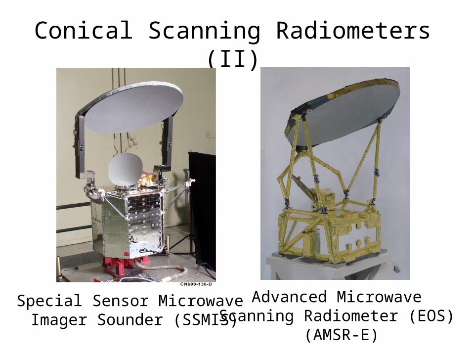
Conical Scanning Radiometers (II)
Advanced Microwave Scanning Radiometer (EOS)
(AMSR-E)
Special Sensor Microwave Imager Sounder (SSMIS)

Summary
• CMIS offers:– New operational data products
• Sea Surface Wind Direction• Soil Moisture• Cloud Base Height
– Quantifiable improvements in heritage data products
• Spatial Resolution• Measurement Range