novenco axial flow fans - inexco · novenco axial flow fans novax — standard and hot smoke. 2...
TRANSCRIPT
Novenco Axial Flow Fans
Novax — Standard and hot Smoke
2 Novax
Product facts
Product
Axial flow fans with adjustable blades.
• ACN for duct installation• ACG free intake with connec-
tion to duct• ACP free suction and ex-
haust, for wall mounting
Application
Novax axial flow fans are used for standard installations in connec-tion with comfort and industrial ventilation including removal of hot smoke in case of fire.
Range
The series of Novax axial fans is of-fered in 14 sizes with rotor diame-ters from Ø250 to Ø1600 mm for standard fans and in 12 sizes with rotor diameters from Ø400 to Ø1600 mm for hot smoke fans.There are seven sizes of hub diam-eters from Ø160 to Ø578 mm for both types of fans.The air flow rates run from 0.1 to 65 m3/s with increases in pressure up to 2000 Pa for standard fans and from 0.2 to 65 m3/s with increases in pressure up to 2000 Pa for hot smoke fans.
Standard motors
ACN, ACP and ACG
Dimension standard: IEC-72Electrical standard: IEC-34Enclosure: IP-55 or IP-54Insulation: Class B, F or HBalancing: ISO 2373Structural shape: B14 and B5 (flanges)
Important The choice of motor manufacturer and sizes is limited due to special requirements for instal-lation. This applies es-pecially for type ACN.
Materials
Blades: Aluminium or glass fibre reinforced polyester (GRP). Please note that rotors with hub sizes Ø403 and Ø578 mm, only are made with aluminium blades.Hot smoke fans are made only with blades of aluminium.Hub: Hot-dip galvanised sheet steel (Sendzimir galvanised)Fan housing: Hot-rolled, hot-dip galvanised sheet steel
Flange standard
Flanges are in accordance with EU-ROVENT 1/2.
Classifications
Technical capacity in accordance with BS 848:1980 and ISO 5801:1997.
The fans meet the requirements for operation in unheated, low-corro-sion environments in accordance with DS /EN ISO 12944 - 2,Corrosion category C3.
The temperature range for the fans is as standard -20 to +50 °C. Max. temperature range is -40 to +120 °C. GRP-blades are limited to max. +70 °C.At -40 to -20 °C and +40 to +120 °C, with reduced RPMs and special motors.Fans used for hot smoke removal are approved in class F300 accord-ing to EN 12101-3 to operate for at least 60 min. at 300 °C. In addition, type ACN is approved according to EN 12101-3 to operate for at least 120 min. at 400 °C.
Accessories
• Mounting feet• Mounting plates• Inlet cones with wire guard• Counter flanges• Duct spigots• Flexible connections• Silencers with or without
cores• Acoustic diffusers with cores• Spark proof lining• Anti-vibration mountings• Diffusers• Welding spigots• Outlet wire guards• Downstream guide vane ar-
rangement
Hub Diameters[mm]
Number of BladesNovax
Ø160 4Ø230 6Ø280 8Ø330 10Ø380 12Ø403 6Ø578 10
Number of blades according to hub diameter
Hub Diameters[mm] Motor Sizes
Ø160 – ACN– ACP/G
71 - 8071 - 100
Ø230 71 - 100Ø280 71 - 112Ø330 80 - 132Ø380 90 - 180Ø403 112 - 180Ø578 132 - 250 / 280 (ACN)
ACN, ACP and ACG motor sizes
Novax 3
MU 14329 0810
Contents
ImportantThis document is provided ‘As is’ and is subject to change without notice. Novenco reserves this right due to continuous product de-velopment.
The fan is designed for continuous operation. The following kinds of operation may cause fatigue break in the impeller and endanger people.
• Operation in stall area• Operation with pulsating counter pressure – called pump
mode• Operation with repeated starting and stopping
If in doubt Novenco should be contacted to assess the suitability of the fan.
Copyright (c) 2002 – 2010, Novenco A/S.All rights reserved
TrademarksNovenco is a trademark of Novenco A/S.
Other trademarks appearing in this document are the property of their respective owners.
Description 4
RPMs and frequency regulation 5
Type descriptions 6
Overview of types and accessories 8
Performance curves for ACN at 50 Hz 10
Performance curves for ACG at 50 Hz 12
Performance curves for ACP at 50 Hz 14
Dimensions 16
Accessories 18
Calculations 26
4 Novax
Description
Novax are compact, robust, series-produced axial flow fans with presettable blades.
Novax fans are installed in a wide range of ventilation systems on shore and off-shore: Comfort systems, in-dustrial, process, parking and tunnel ventilation as well as environment-enhancement systems. The fans require little space, are easy to install and offer high operational reliability.
Novax fan types
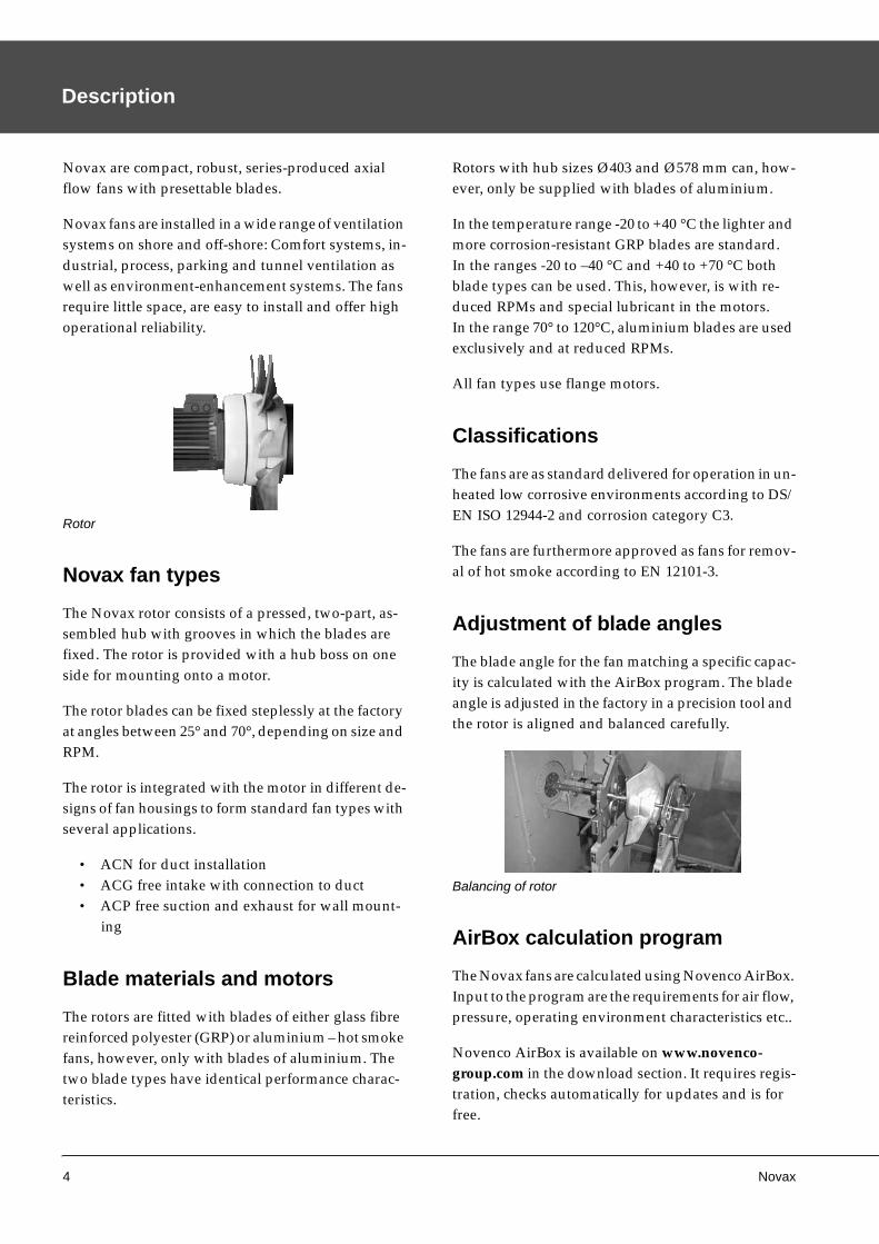
The Novax rotor consists of a pressed, two-part, as-sembled hub with grooves in which the blades are fixed. The rotor is provided with a hub boss on one side for mounting onto a motor.
The rotor blades can be fixed steplessly at the factory at angles between 25° and 70°, depending on size and RPM.
The rotor is integrated with the motor in different de-signs of fan housings to form standard fan types with several applications.
• ACN for duct installation• ACG free intake with connection to duct• ACP free suction and exhaust for wall mount-
ing
Blade materials and motors
The rotors are fitted with blades of either glass fibre reinforced polyester (GRP) or aluminium – hot smoke fans, however, only with blades of aluminium. The two blade types have identical performance charac-teristics.
Rotors with hub sizes Ø403 and Ø578 mm can, how-ever, only be supplied with blades of aluminium.
In the temperature range -20 to +40 °C the lighter and more corrosion-resistant GRP blades are standard.In the ranges -20 to –40 °C and +40 to +70 °C both blade types can be used. This, however, is with re-duced RPMs and special lubricant in the motors.In the range 70° to 120°C, aluminium blades are used exclusively and at reduced RPMs.
All fan types use flange motors.
Classifications
The fans are as standard delivered for operation in un-heated low corrosive environments according to DS/EN ISO 12944-2 and corrosion category C3.
The fans are furthermore approved as fans for remov-al of hot smoke according to EN 12101-3.
Adjustment of blade angles
The blade angle for the fan matching a specific capac-ity is calculated with the AirBox program. The blade angle is adjusted in the factory in a precision tool and the rotor is aligned and balanced carefully.
AirBox calculation program
The Novax fans are calculated using Novenco AirBox. Input to the program are the requirements for air flow, pressure, operating environment characteristics etc..
Novenco AirBox is available on www.novenco-group.com in the download section. It requires regis-tration, checks automatically for updates and is for free.
Rotor
Balancing of rotor
Novax 5
RPMs and frequency regulation
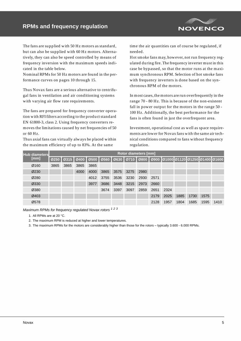
The fans are supplied with 50 Hz motors as standard, but can also be supplied with 60 Hz motors. Alterna-tively, they can also be speed controlled by means of frequency inversion with the maximum speeds indi-cated in the table below.Nominal RPMs for 50 Hz motors are found in the per-formance curves on pages 10 through 15.
Thus Novax fans are a serious alternative to centrifu-gal fans in ventilation and air conditioning systems with varying air flow rate requirements.
The fans are prepared for frequency converter opera-tion with RFI filters according to the product standard EN 61800-3, class 2. Using frequency converters re-moves the limitations caused by net frequencies of 50 or 60 Hz.Thus axial fans can virtually always be placed within the maximum efficiency of up to 83%. At the same
time the air quantities can of course be regulated, if needed.Hot smoke fans may, however, not run frequency reg-ulated during fire. The frequency inverter must in this case be bypassed, so that the motor runs at the maxi-mum synchronous RPM. Selection of hot smoke fans with frequency inverters is done based on the syn-chronous RPM of the motors.
In most cases, the motors are run overfrequently in the range 70 - 80 Hz. This is because of the non-existent fall in power output for the motors in the range 50 - 100 Hz. Additionally, the best performance for the fans is often found in just the overfrequent area.
Investment, operational cost as well as space require-ments are lower for Novax fans with the same air tech-nical conditions compared to fans without frequency regulation.
Hub diameters[mm]
Rotor diameters [mm]
Ø250 Ø315 Ø400 Ø500 Ø560 Ø630 Ø710 Ø800 Ø900 Ø1000 Ø1120 Ø1250 Ø1400 Ø1600
Ø160 3865 3865 3865 3865
Ø230 4000 4000 3865 3575 3275 2980
Ø280 4012 3755 3536 3230 2930 2571
Ø330 3977 3686 3448 3215 2973 2660
Ø380 3674 3397 3097 2859 2651 2324
Ø403 2179 2025 1885 1730 1575
Ø578 2128 1957 1804 1685 1595 1410
Maximum RPMs for frequency regulated Novax rotors 1 2 3
1. All RPMs are at 20 °C.
2. The maximum RPM is reduced at higher and lower temperatures.
3. The maximum RPMs for the motors are considerably higher than those for the rotors – typically 3.600 - 6.000 RPMs.
6 Novax
Type descriptions
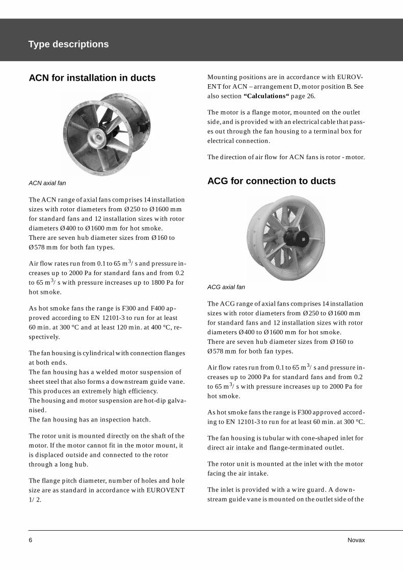
ACN for installation in ducts
The ACN range of axial fans comprises 14 installation sizes with rotor diameters from Ø250 to Ø1600 mm for standard fans and 12 installation sizes with rotor diameters Ø400 to Ø1600 mm for hot smoke.There are seven hub diameter sizes from Ø160 to Ø578 mm for both fan types.
Air flow rates run from 0.1 to 65 m3/s and pressure in-creases up to 2000 Pa for standard fans and from 0.2 to 65 m3/s with pressure increases up to 1800 Pa for hot smoke.
As hot smoke fans the range is F300 and F400 ap-proved according to EN 12101-3 to run for at least 60 min. at 300 °C and at least 120 min. at 400 °C, re-spectively.
The fan housing is cylindrical with connection flanges at both ends.The fan housing has a welded motor suspension of sheet steel that also forms a downstream guide vane. This produces an extremely high efficiency.The housing and motor suspension are hot-dip galva-nised.The fan housing has an inspection hatch.
The rotor unit is mounted directly on the shaft of the motor. If the motor cannot fit in the motor mount, it is displaced outside and connected to the rotor through a long hub.
The flange pitch diameter, number of holes and hole size are as standard in accordance with EUROVENT 1/2.
Mounting positions are in accordance with EUROV-ENT for ACN – arrangement D, motor position B. See also section “Calculations“ page 26.
The motor is a flange motor, mounted on the outlet side, and is provided with an electrical cable that pass-es out through the fan housing to a terminal box for electrical connection.
The direction of air flow for ACN fans is rotor - motor.
ACG for connection to ducts
The ACG range of axial fans comprises 14 installation sizes with rotor diameters from Ø250 to Ø1600 mm for standard fans and 12 installation sizes with rotor diameters Ø400 to Ø1600 mm for hot smoke.There are seven hub diameter sizes from Ø160 to Ø578 mm for both fan types.
Air flow rates run from 0.1 to 65 m3/s and pressure in-creases up to 2000 Pa for standard fans and from 0.2 to 65 m3/s with pressure increases up to 2000 Pa for hot smoke.
As hot smoke fans the range is F300 approved accord-ing to EN 12101-3 to run for at least 60 min. at 300 °C.
The fan housing is tubular with cone-shaped inlet for direct air intake and flange-terminated outlet.
The rotor unit is mounted at the inlet with the motor facing the air intake.
The inlet is provided with a wire guard. A down-stream guide vane is mounted on the outlet side of the
ACN axial fan
ACG axial fan
Novax 7
rotor, enabling the ACG to achieve a very high effi-ciency.
The flange pitch diameter, number of holes and hole size are as standard in accordance with EUROVENT 1/2.
Mounting positions are in accordance with EUROV-ENT for ACG – arrangement B, motor position A. See also section “Calculations“ page 26.
The motor is a flange motor with electrical connection in the terminal box.
The direction of air flow for ACG is motor - rotor.
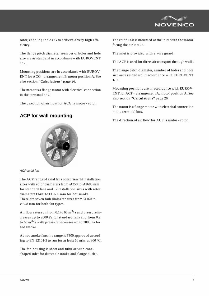
ACP for wall mounting
The ACP range of axial fans comprises 14 installation sizes with rotor diameters from Ø250 to Ø1600 mm for standard fans and 12 installation sizes with rotor diameters Ø400 to Ø1600 mm for hot smoke.There are seven hub diameter sizes from Ø160 to Ø578 mm for both fan types.
Air flow rates run from 0.1 to 65 m3/s and pressure in-creases up to 2000 Pa for standard fans and from 0.2 to 65 m3/s with pressure increases up to 2000 Pa for hot smoke.
As hot smoke fans the range is F300 approved accord-ing to EN 12101-3 to run for at least 60 min. at 300 °C.
The fan housing is short and tubular with cone-shaped inlet for direct air intake and flange outlet.
The rotor unit is mounted at the inlet with the motor facing the air intake.
The inlet is provided with a wire guard.
The ACP is used for direct air transport through walls.
The flange pitch diameter, number of holes and hole size are as standard in accordance with EUROVENT 1/2.
Mounting positions are in accordance with EUROV-ENT for ACP – arrangement A, motor position A. See also section “Calculations“ page 26.
The motor is a flange motor with electrical connection in the terminal box.
The direction of air flow for ACP is motor - rotor.
ACP axial fan
8 Novax
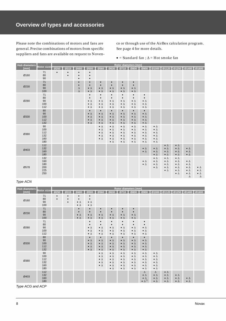
Overview of types and accessories
Please note the combinations of motors and fans are general. Precise combinations of motors from specific suppliers and fans are available on request to Noven-
co or through use of the AirBox calculation program. See page 4 for more details.
• = Standard fan ; Δ = Hot smoke fan
Hub diameters[mm] Motor sizes
Rotor diameters [mm]Ø250 Ø315 Ø400 Ø500 Ø560 Ø630 Ø710 Ø800 Ø900 Ø1000 Ø1120 Ø1250 Ø1400 Ø1600
Ø160718090
• ••
•••
•••
Ø230
718090
100
••ΔΔ
••
• Δ• Δ
••
• Δ• Δ
••
• Δ• Δ
••
• Δ• Δ
••
• Δ• Δ
Ø280
718090
100112
••
• Δ• Δ• Δ
••
• Δ• Δ• Δ
••
• Δ• Δ• Δ
••
• Δ• Δ• Δ
••
• Δ• Δ• Δ
••
• Δ• Δ• Δ
Ø330
8090
100112132
•• Δ• Δ• Δ• Δ
•• Δ• Δ• Δ• Δ
•• Δ• Δ• Δ• Δ
•• Δ• Δ• Δ• Δ
•• Δ• Δ• Δ• Δ
•• Δ• Δ• Δ• Δ
Ø380
90100112132160180
• Δ• Δ• Δ• Δ• Δ
• Δ• Δ• Δ• Δ• Δ• Δ
• Δ• Δ• Δ• Δ• Δ• Δ
• Δ• Δ• Δ• Δ• Δ• Δ
• Δ• Δ• Δ• Δ• Δ• Δ
• Δ• Δ• Δ• Δ• Δ• Δ
Ø403
112132160180
• Δ• Δ
• Δ• Δ• Δ
• Δ• Δ• Δ• Δ
• Δ• Δ• Δ• Δ
• Δ• Δ• Δ
Ø578
132160180200225250
• Δ• Δ
• Δ• Δ• Δ• Δ
• Δ• Δ• Δ• Δ• Δ
• Δ• Δ• Δ• Δ• Δ• Δ
• Δ• Δ• Δ• Δ• Δ
Δ
• Δ• Δ• Δ
Δ
Type ACN
Hub diameters[mm] Motor sizes
Rotor diameters [mm]Ø250 Ø315 Ø400 Ø500 Ø560 Ø630 Ø710 Ø800 Ø900 Ø1000 Ø1120 Ø1250 Ø1400 Ø1600
Ø160
718090
100
••
•••
••
• Δ• Δ
••
• Δ• Δ
Ø230
718090
100
••
• Δ• Δ
••
• Δ• Δ
••
• Δ• Δ
••
• Δ• Δ
••
• Δ• Δ
••
• Δ• Δ
Ø280
718090
100112
••
• Δ• Δ• Δ
••
• Δ• Δ• Δ
••
• Δ• Δ• Δ
••
• Δ• Δ• Δ
••
• Δ• Δ• Δ
••
• Δ• Δ• Δ
Ø330
8090
100112132
•• Δ• Δ• Δ• Δ
•• Δ• Δ• Δ• Δ
•• Δ• Δ• Δ• Δ
•• Δ• Δ• Δ• Δ
•• Δ• Δ• Δ• Δ
•• Δ• Δ• Δ• Δ
Ø380
90100112132160180
• Δ• Δ• Δ• Δ• Δ
• Δ• Δ• Δ• Δ• Δ• Δ
• Δ• Δ• Δ• Δ• Δ• Δ
• Δ• Δ• Δ• Δ• Δ• Δ
• Δ• Δ• Δ• Δ• Δ• Δ
• Δ• Δ• Δ• Δ• Δ• Δ
Ø403
112132160180
Δ• Δ• Δ
• Δ 1
Δ• Δ• Δ• Δ
• Δ• Δ• Δ• Δ
• Δ• Δ• Δ
• Δ• Δ
Type ACG and ACP
Novax 9
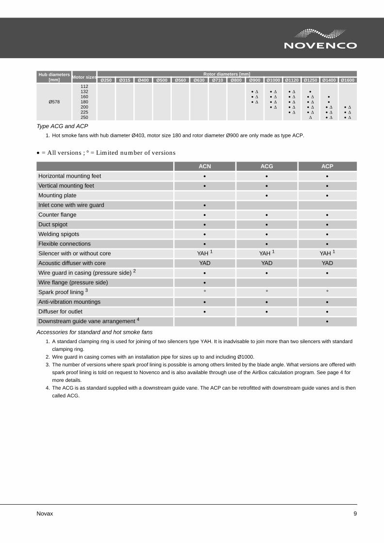
• = All versions ; ° = Limited number of versions
Ø578
112132160180200225250
• Δ• Δ• Δ
• Δ• Δ• Δ• Δ
• Δ• Δ• Δ• Δ• Δ
•• Δ• Δ• Δ• ΔΔ
••
• Δ• Δ• Δ
• Δ• Δ• Δ
1. Hot smoke fans with hub diameter Ø403, motor size 180 and rotor diameter Ø900 are only made as type ACP.
Hub diameters[mm] Motor sizes
Rotor diameters [mm]Ø250 Ø315 Ø400 Ø500 Ø560 Ø630 Ø710 Ø800 Ø900 Ø1000 Ø1120 Ø1250 Ø1400 Ø1600
Type ACG and ACP
ACN ACG ACP
Horizontal mounting feet • • •
Vertical mounting feet • • •
Mounting plate • •
Inlet cone with wire guard •
Counter flange • • •
Duct spigot • • •
Welding spigots • • •
Flexible connections • • •
Silencer with or without core YAH 1 YAH 1 YAH 1
Acoustic diffuser with core YAD YAD YAD
Wire guard in casing (pressure side) 2 • • •
Wire flange (pressure side) •
Spark proof lining 3 ° ° °
Anti-vibration mountings • • •
Diffuser for outlet • • •
Downstream guide vane arrangement 4 •
Accessories for standard and hot smoke fans
1. A standard clamping ring is used for joining of two silencers type YAH. It is inadvisable to join more than two silencers with standard
clamping ring.
2. Wire guard in casing comes with an installation pipe for sizes up to and including Ø1000.
3. The number of versions where spark proof lining is possible is among others limited by the blade angle. What versions are offered with
spark proof lining is told on request to Novenco and is also available through use of the AirBox calculation program. See page 4 for
more details.
4. The ACG is as standard supplied with a downstream guide vane. The ACP can be retrofitted with downstream guide vanes and is then
called ACG.
10 Novax
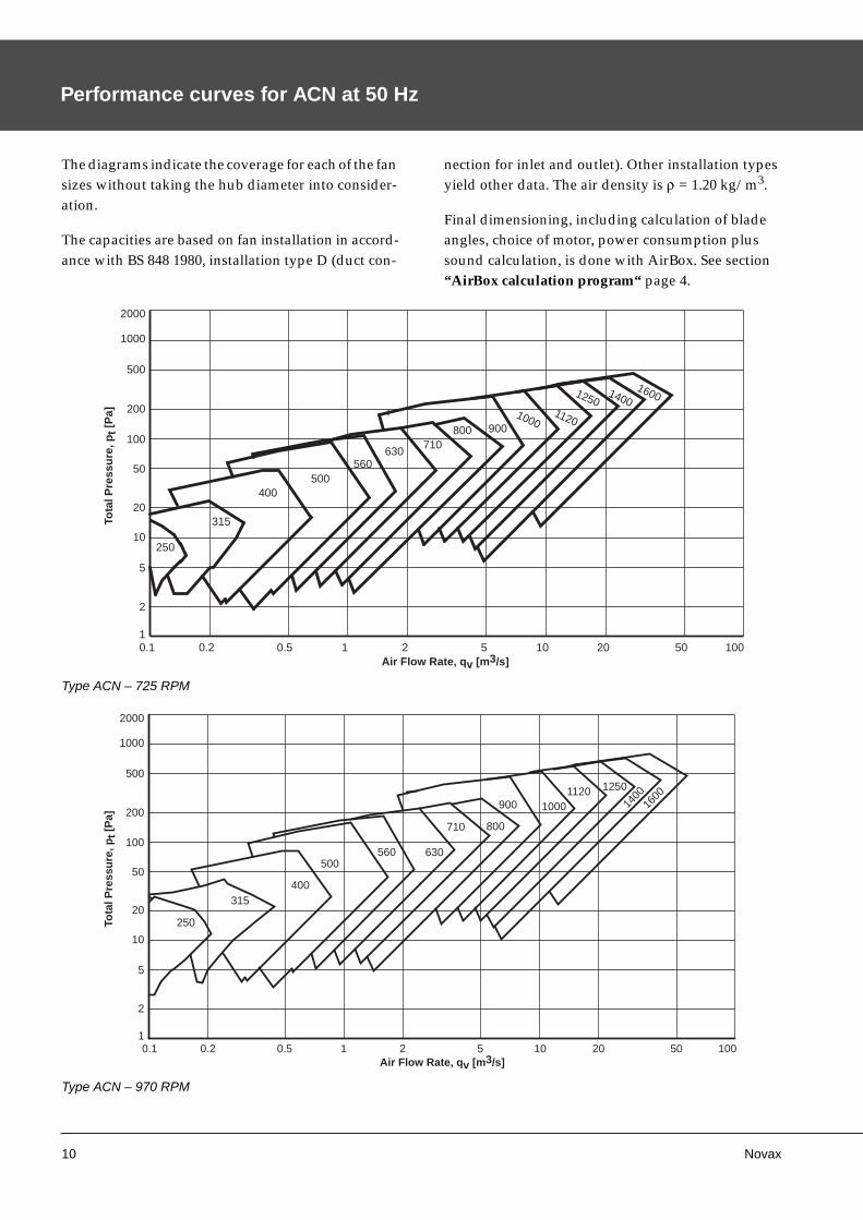
Performance curves for ACN at 50 Hz
The diagrams indicate the coverage for each of the fan sizes without taking the hub diameter into consider-ation.
The capacities are based on fan installation in accord-ance with BS 848 1980, installation type D (duct con-
nection for inlet and outlet). Other installation types yield other data. The air density is ρ = 1.20 kg/m3.
Final dimensioning, including calculation of blade angles, choice of motor, power consumption plus sound calculation, is done with AirBox. See section “AirBox calculation program“ page 4.
Type ACN – 725 RPM
Type ACN – 970 RPM
1
2000
1000
500
200
100
50
20
10
5
2
250
315
400500
560630
710800 900
10001120
12501400
1600
20 50 1000.1 0.5 1 2 5 100.2
Tota
l Pre
ssu
re, p
t [P
a]
Air Flow Rate, qv [m3/s]
1
2000
1000
500
200
100
50
20
10
5
2
250
315400
500560 630
710 800
900 10001120 1250
1400
1600
20 50 1000.1 0.5 1 2 5 100.2
Tota
l Pre
ssu
re, p
t [P
a]
Air Flow Rate, qv [m3/s]
Novax 11
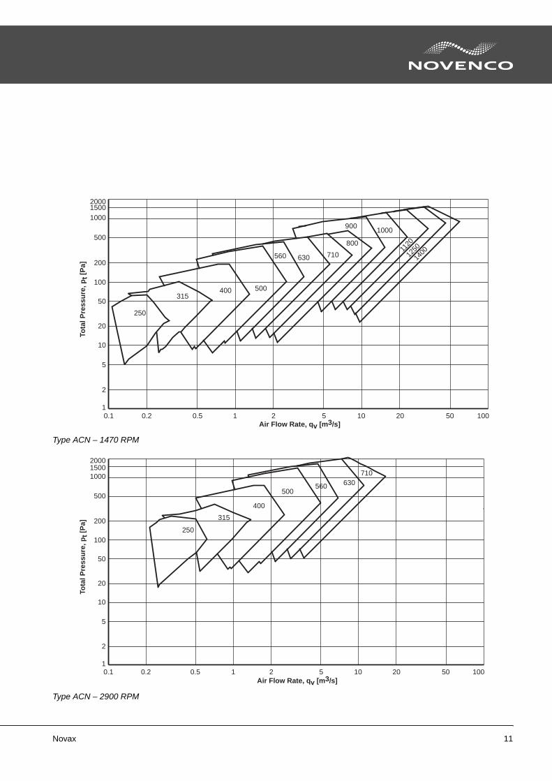
Type ACN – 1470 RPM
Type ACN – 2900 RPM
1
2000
1000
500
200
100
50
20
10
5
2
250
315400 500
560 630 710
800
9001000
1120
1250
1400
1500
20 50 1000.1 0.5 1 2 5 100.2
Tota
l Pre
ssu
re, p
t [P
a]
Air Flow Rate, qv [m3/s]
1
2000
1000
500
200
100
50
20
10
5
2
1500
250
315
400
500560 630
710
20 50 1000.1 0.5 1 2 5 100.2
Tota
l Pre
ssu
re, p
t [P
a]
Air Flow Rate, qv [m3/s]
12 Novax
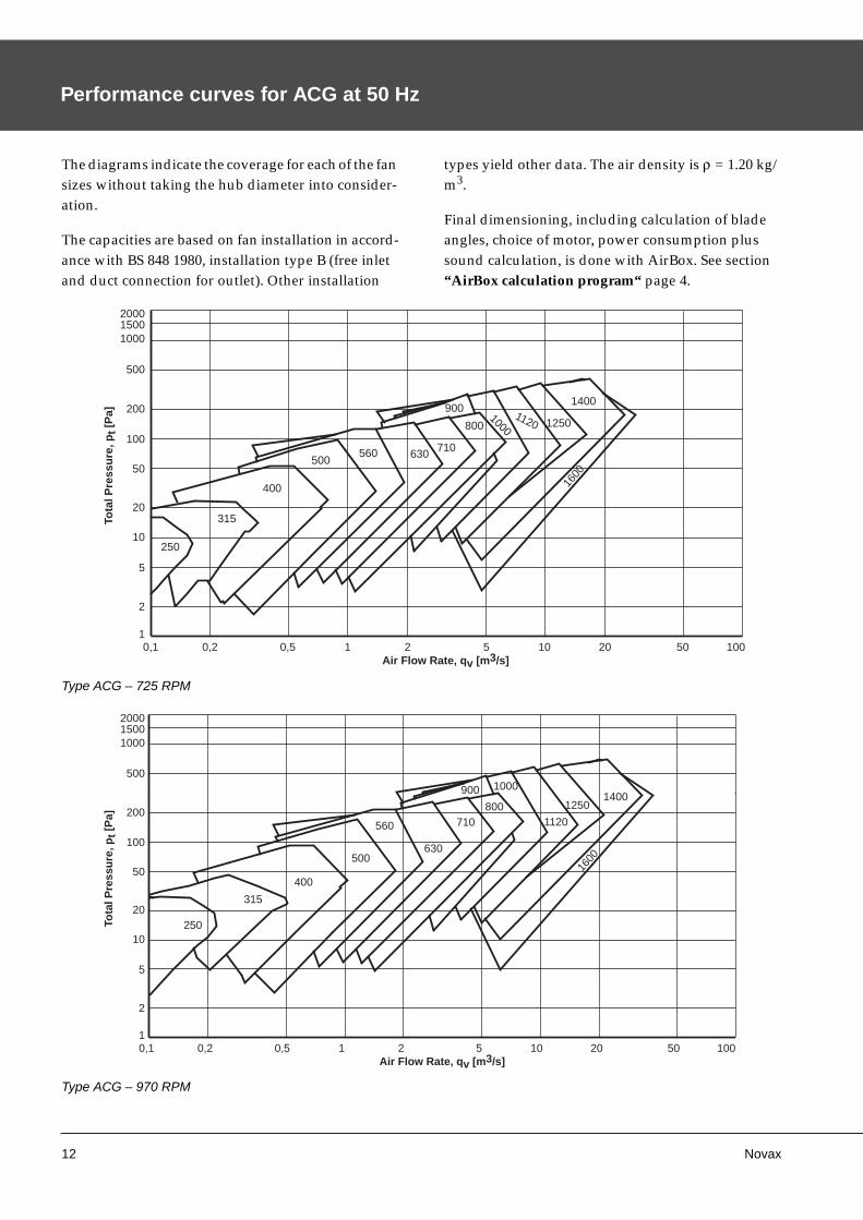
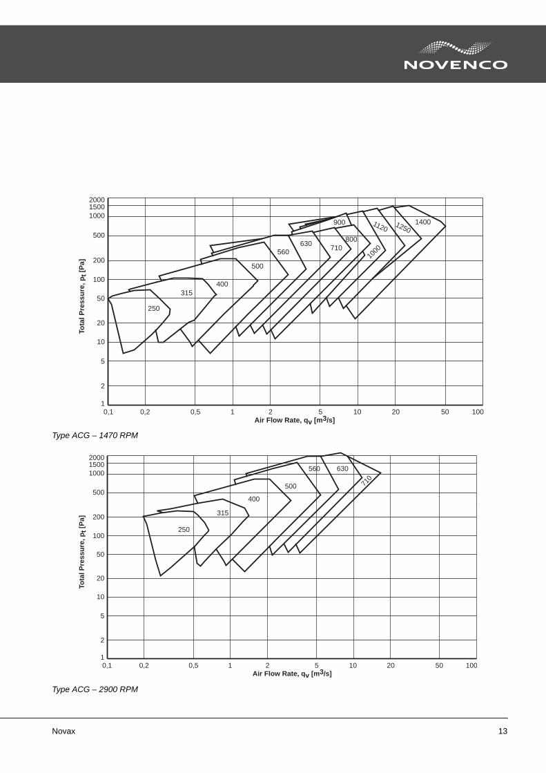
Performance curves for ACG at 50 Hz
The diagrams indicate the coverage for each of the fan sizes without taking the hub diameter into consider-ation.
The capacities are based on fan installation in accord-ance with BS 848 1980, installation type B (free inlet and duct connection for outlet). Other installation
types yield other data. The air density is ρ = 1.20 kg/m3.
Final dimensioning, including calculation of blade angles, choice of motor, power consumption plus sound calculation, is done with AirBox. See section “AirBox calculation program“ page 4.
Type ACG – 725 RPM
Type ACG – 970 RPM
1
2000
1000
500
200
100
50
20
10
5
2
1500
1400
12501120
1000800
900
710630560500
400
315
25016
00
20 50 1000,1 0,5 1 2 5 100,2
Tota
l Pre
ssu
re, p
t [P
a]
Air Flow Rate, qv [m3/s]
1
2000
1000
500
200
100
50
20
10
5
2
1500
250
315
400
500
560
630
710800
900 1000
1120
12501400
1600
20 50 1000,1 0,5 1 2 5 100,2
Tota
l Pre
ssu
re, p
t [P
a]
Air Flow Rate, qv [m3/s]
Novax 13
Type ACG – 1470 RPM
Type ACG – 2900 RPM
1
2000
1000
500
200
100
50
20
10
5
2
1500
250
315400
500
560630
710800
900
1000
11201250
1400
20 50 1000,1 0,5 1 2 5 100,2
Tota
l Pre
ssu
re, p
t [P
a]
Air Flow Rate, qv [m3/s]
1
2000
1000
500
200
100
50
20
10
5
2
1500
250
315
400
500
560 630
710
20 50 1000,1 0,5 1 2 5 100,2
Tota
l Pre
ssu
re, p
t [P
a]
Air Flow Rate, qv [m3/s]
14 Novax
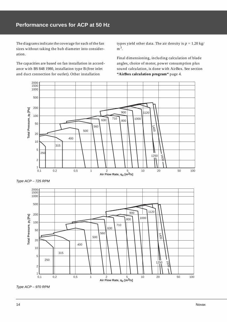
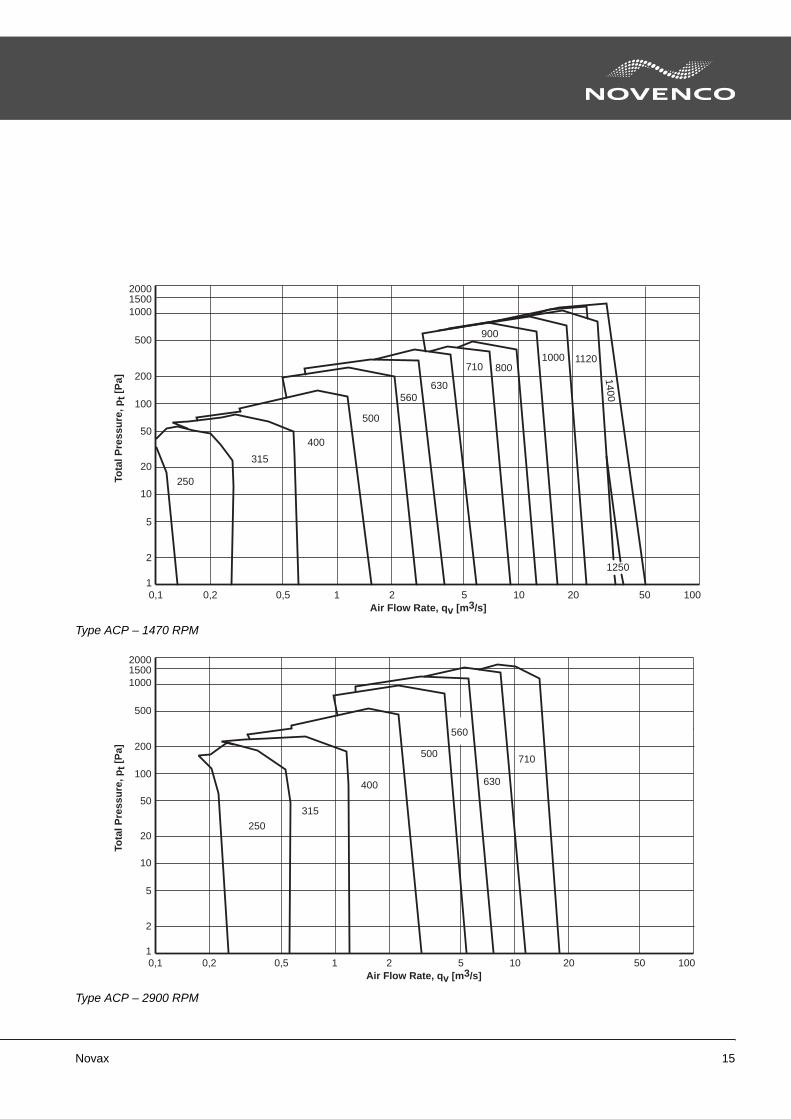
Performance curves for ACP at 50 Hz
The diagrams indicate the coverage for each of the fan sizes without taking the hub diameter into consider-ation.
The capacities are based on fan installation in accord-ance with BS 848 1980, installation type B (free inlet and duct connection for outlet). Other installation
types yield other data. The air density is ρ = 1.20 kg/m3.
Final dimensioning, including calculation of blade angles, choice of motor, power consumption plus sound calculation, is done with AirBox. See section “AirBox calculation program“ page 4.
Type ACP – 725 RPM
Type ACP – 970 RPM
1
2000
1000
500
200
100
50
20
10
5
2
1500
250
315
400
500
560
630 710800
900
1000
1120
1400
1600
1250
20 50 1000,1 0,5 1 2 5 100,2
Tota
l Pre
ssu
re, p
t [P
a]
Air Flow Rate, qv [m3/s]
1
2000
1000
500
200
100
50
20
10
5
2
1500
250
315
400
500560
630710
800
900
1000
1120
1400
1600
1250
20 50 1000,1 0,5 1 2 5 100,2
Tota
l Pre
ssu
re, p
t [P
a]
Air Flow Rate, qv [m3/s]
Novax 15
Type ACP – 1470 RPM
Type ACP – 2900 RPM
1
2000
1000
500
200
100
50
20
10
5
2
1500
250
315
400
500
560630
710 800
900
1000 1120
1400
1250
20 50 1000,1 0,5 1 2 5 100,2
Tota
l Pre
ssu
re, p
t [P
a]
Air Flow Rate, qv [m3/s]
1
2000
1000
500
200
100
50
20
10
5
2
1500
250
315
400
500
560
630
710
20 50 1000,1 0,5 1 2 5 100,2
Tota
l Pre
ssu
re, p
t [P
a]
Air Flow Rate, qv [m3/s]
16 Novax
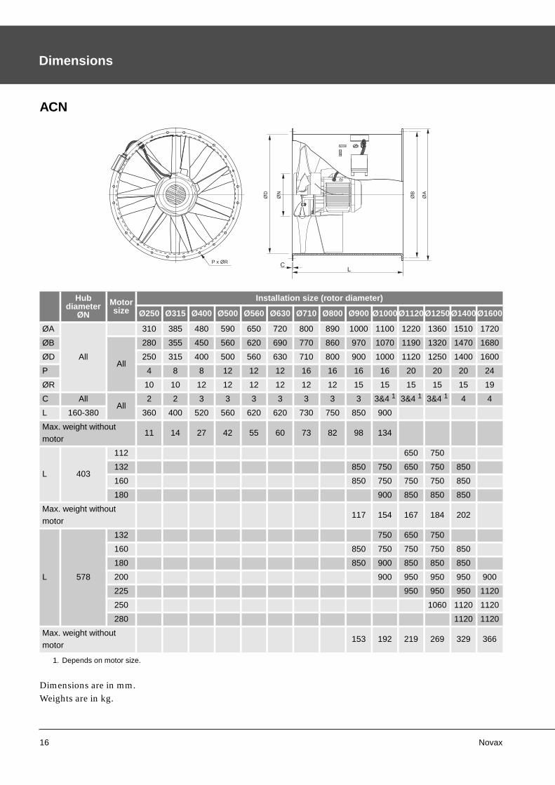
Dimensions
ACN
Dimensions are in mm.Weights are in kg.
Hubdiameter
ØN
Motorsize
Installation size (rotor diameter)
Ø250 Ø315 Ø400 Ø500 Ø560 Ø630 Ø710 Ø800 Ø900 Ø1000Ø1120Ø1250Ø1400Ø1600
ØA
All
310 385 480 590 650 720 800 890 1000 1100 1220 1360 1510 1720
ØB
All
280 355 450 560 620 690 770 860 970 1070 1190 1320 1470 1680
ØD 250 315 400 500 560 630 710 800 900 1000 1120 1250 1400 1600
P 4 8 8 12 12 12 16 16 16 16 20 20 20 24
ØR 10 10 12 12 12 12 12 12 15 15 15 15 15 19
C AllAll
2 2 3 3 3 3 3 3 3 3&4 1 3&4 1 3&4 1 4 4
L 160-380 360 400 520 560 620 620 730 750 850 900
Max. weight without
motor11 14 27 42 55 60 73 82 98 134
L 403
112 650 750
132 850 750 650 750 850
160 850 750 750 750 850
180 900 850 850 850
Max. weight withoutmotor
117 154 167 184 202
L 578
132 750 650 750
160 850 750 750 750 850
180 850 900 850 850 850
200 900 950 950 950 900
225 950 950 950 1120
250 1060 1120 1120
280 1120 1120
Max. weight without
motor153 192 219 269 329 366
1. Depends on motor size.
LCP x ØR
ØA
ØB
ØN
ØD
Novax 17
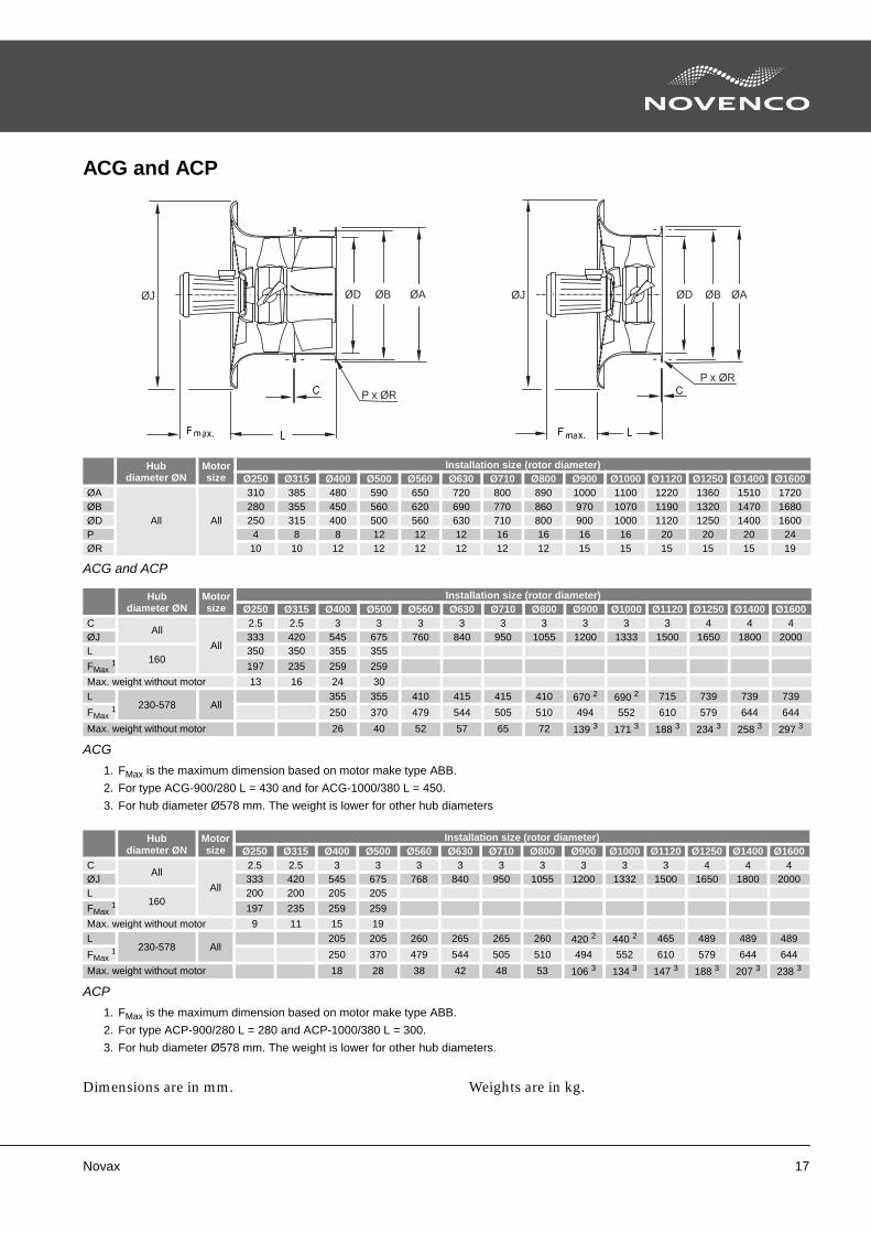
ACG and ACP
Dimensions are in mm. Weights are in kg.
Hubdiameter ØN
Motorsize
Installation size (rotor diameter)Ø250 Ø315 Ø400 Ø500 Ø560 Ø630 Ø710 Ø800 Ø900 Ø1000 Ø1120 Ø1250 Ø1400 Ø1600
ØA
All All
310 385 480 590 650 720 800 890 1000 1100 1220 1360 1510 1720ØB 280 355 450 560 620 690 770 860 970 1070 1190 1320 1470 1680ØD 250 315 400 500 560 630 710 800 900 1000 1120 1250 1400 1600P 4 8 8 12 12 12 16 16 16 16 20 20 20 24ØR 10 10 12 12 12 12 12 12 15 15 15 15 15 19
ACG and ACP
Hubdiameter ØN
Motorsize
Installation size (rotor diameter)Ø250 Ø315 Ø400 Ø500 Ø560 Ø630 Ø710 Ø800 Ø900 Ø1000 Ø1120 Ø1250 Ø1400 Ø1600
CAll
All
2.5 2.5 3 3 3 3 3 3 3 3 3 4 4 4ØJ 333 420 545 675 760 840 950 1055 1200 1333 1500 1650 1800 2000L
160350 350 355 355
FMax 1 197 235 259 259
Max. weight without motor 13 16 24 30L
230-578 All355 355 410 415 415 410 670 2 690 2 715 739 739 739
FMax 1 250 370 479 544 505 510 494 552 610 579 644 644
Max. weight without motor 26 40 52 57 65 72 139 3 171 3 188 3 234 3 258 3 297 3
ACG
1. FMax is the maximum dimension based on motor make type ABB.
2. For type ACG-900/280 L = 430 and for ACG-1000/380 L = 450.
3. For hub diameter Ø578 mm. The weight is lower for other hub diameters
Hubdiameter ØN
Motorsize
Installation size (rotor diameter)Ø250 Ø315 Ø400 Ø500 Ø560 Ø630 Ø710 Ø800 Ø900 Ø1000 Ø1120 Ø1250 Ø1400 Ø1600
CAll
All
2.5 2.5 3 3 3 3 3 3 3 3 3 4 4 4ØJ 333 420 545 675 768 840 950 1055 1200 1332 1500 1650 1800 2000L
160200 200 205 205
FMax 1 197 235 259 259
Max. weight without motor 9 11 15 19L
230-578 All205 205 260 265 265 260 420 2 440 2 465 489 489 489
FMax 1 250 370 479 544 505 510 494 552 610 579 644 644
Max. weight without motor 18 28 38 42 48 53 106 3 134 3 147 3 188 3 207 3 238 3
ACP
1. FMax is the maximum dimension based on motor make type ABB.
2. For type ACP-900/280 L = 280 and ACP-1000/380 L = 300.
3. For hub diameter Ø578 mm. The weight is lower for other hub diameters.
P x ØR
ØBØD ØAØJ ØJ
P x ØR
ØBØD ØA
18 Novax
Accessories
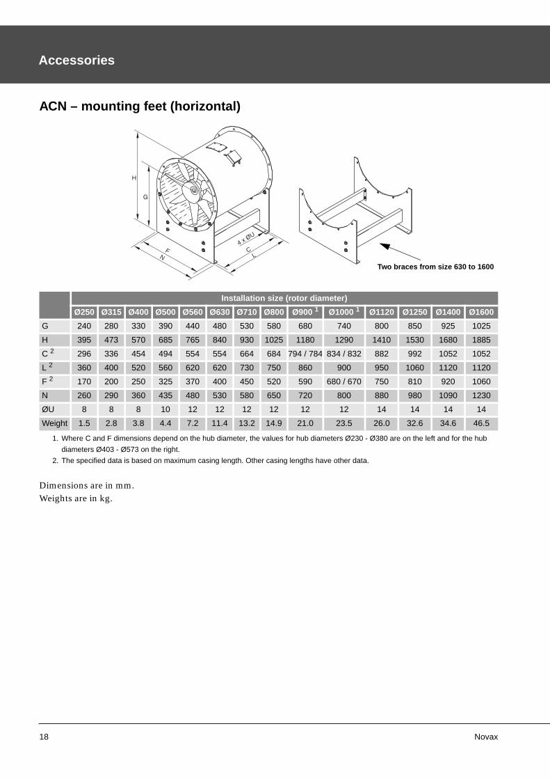
ACN – mounting feet (horizontal)
Dimensions are in mm.Weights are in kg.
Installation size (rotor diameter)
Ø250 Ø315 Ø400 Ø500 Ø560 Ø630 Ø710 Ø800 Ø900 1 Ø1000 1 Ø1120 Ø1250 Ø1400 Ø1600
G 240 280 330 390 440 480 530 580 680 740 800 850 925 1025
H 395 473 570 685 765 840 930 1025 1180 1290 1410 1530 1680 1885
C 2 296 336 454 494 554 554 664 684 794 / 784 834 / 832 882 992 1052 1052
L 2 360 400 520 560 620 620 730 750 860 900 950 1060 1120 1120
F 2 170 200 250 325 370 400 450 520 590 680 / 670 750 810 920 1060
N 260 290 360 435 480 530 580 650 720 800 880 980 1090 1230
ØU 8 8 8 10 12 12 12 12 12 12 14 14 14 14
Weight 1.5 2.8 3.8 4.4 7.2 11.4 13.2 14.9 21.0 23.5 26.0 32.6 34.6 46.5
1. Where C and F dimensions depend on the hub diameter, the values for hub diameters Ø230 - Ø380 are on the left and for the hub
diameters Ø403 - Ø573 on the right.
2. The specified data is based on maximum casing length. Other casing lengths have other data.
FN
H
CL
4 x ØU
Two braces from size 630 to 1600
Novax 19
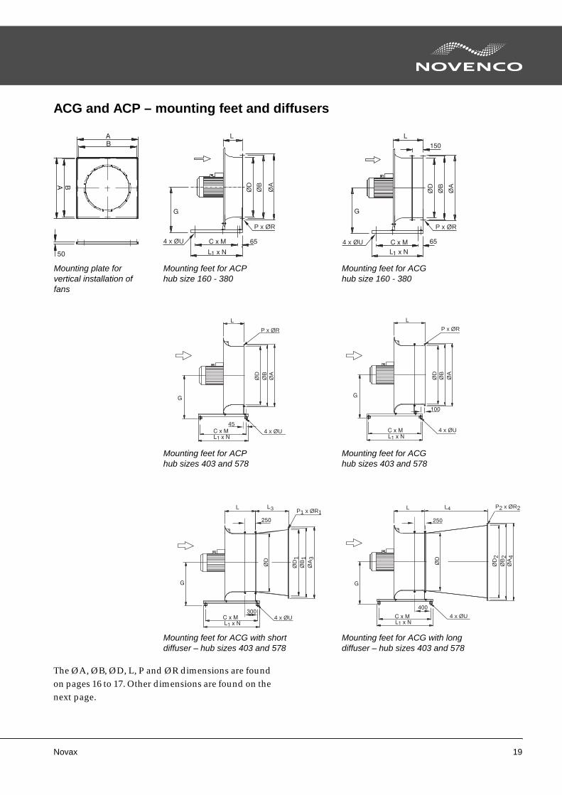
ACG and ACP – mounting feet and diffusers
The ØA, ØB, ØD, L, P and ØR dimensions are found on pages 16 to 17. Other dimensions are found on the next page.
4 x ØU
P x ØR
ØB
ØA
ØD
4 x ØU
P x ØR
ØA
ØB
ØD
4 x ØU
P x ØR
ØA
ØB
ØD
4 x ØU
P x ØR
ØB
ØA
ØD
4 x ØU
P1 x ØR1
ØB
1Ø
A3
ØD
1
ØD
4 x ØU
P2 x ØR2
ØD
ØA
4
ØB
2
ØD
2
Mounting plate for vertical installation of fans
Mounting feet for ACGhub size 160 - 380
Mounting feet for ACPhub size 160 - 380
Mounting feet for ACPhub sizes 403 and 578
Mounting feet for ACGhub sizes 403 and 578
Mounting feet for ACG with short diffuser – hub sizes 403 and 578
Mounting feet for ACG with long diffuser – hub sizes 403 and 578
20 Novax
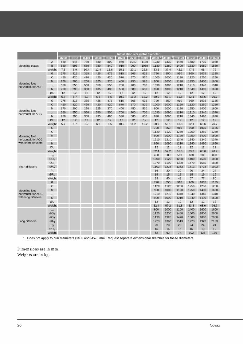
Dimensions are in mm.Weights are in kg.
Installation size (rotor diameter)Ø250 Ø315 Ø400 Ø500 Ø560 Ø630 Ø710 Ø800 Ø900 1 Ø1000 1 Ø1120 Ø1250 Ø1400 Ø1600
Mounting platesA 580 645 730 830 890 960 1040 1130 1230 1330 1450 1580 1730 1930B 530 595 680 780 840 910 990 1080 1180 1280 1400 1530 1680 1880
Weight 7.8 8.9 10.4 12.4 13.6 15.1 20.1 22.6 33.5 37.4 42.1 47.5 68 79
Mounting feet,horizontal, for ACP
G 275 315 365 425 475 515 565 615 790 850 910 960 1035 1135C 420 420 420 420 420 570 570 570 1000 1000 1120 1120 1250 1250M 170 200 250 325 370 400 450 520 900 1000 1120 1250 1400 1600L1 550 550 550 550 550 700 700 700 1090 1090 1210 1210 1340 1340N 260 290 360 435 480 530 580 650 990 1090 1210 1340 1490 1690
ØU 12 12 12 12 12 12 12 12 12 12 12 12 12 12Weight 5.7 5.7 5.7 6.3 8.5 10.2 11.2 12.2 50.9 53.1 61.8 62.1 68.6 76.7
Mounting feet,horizontal for ACG
G 275 315 365 425 475 515 565 615 790 850 910 960 1035 1135C 420 420 420 420 420 570 570 570 1000 1000 1120 1120 1250 1250M 170 200 250 325 370 400 450 520 900 1000 1120 1250 1400 1600L1 550 550 550 550 550 700 700 700 1090 1090 1210 1210 1340 1340N 260 290 360 435 480 530 580 650 990 1090 1210 1340 1490 1690
ØU 12 12 12 12 12 12 12 12 12 12 12 12 12 12Weight 5.7 5.7 5.7 6.3 8.5 10.2 11.2 12.2 50.9 53.1 61.8 62.1 68.6 76.7
Mounting feet,horizontal, for ACG with short diffusers
G 790 850 910 960 1035 1135C 1120 1120 1250 1250 1250 1250M 900 1000 1120 1250 1400 1600L1 1210 1210 1340 1340 1340 1340N 990 1090 1210 1340 1490 1690
ØU 12 12 12 12 12 12Weight 52.4 57.2 61.8 63.8 68.6 76.7
Short diffusers
L3 400 500 560 600 800 800ØD1 1000 1120 1250 1400 1600 1800ØB1 1070 1190 1320 1470 1680 1880ØA3 1103 1223 1363 1513 1723 1923P1 16 20 20 20 24 24
ØR1 15 15 15 15 19 19Weight 33 40 48 57 77 86
Mounting feet,horizontal, for ACGwith long diffusers
G 790 850 910 960 1035 1135C 1120 1120 1250 1250 1250 1250M 900 1000 1120 1250 1400 1600L1 1210 1210 1340 1340 1340 1340N 990 1090 1210 1340 1490 1690
ØU 12 12 12 12 12 12Weight 52.4 57.2 61.8 63.8 68.6 76.7
Long diffusers
L4 900 1000 1100 1400 1600 1600ØD2 1120 1250 1400 1600 1800 2000ØB2 1190 1320 1470 1680 1880 2080ØA4 1223 1363 1513 1723 1923 2123P2 20 20 20 24 24 24
ØR2 15 15 15 15 19 19Weight 52 62 74 102 123 139
1. Does not apply to hub diameters Ø403 and Ø578 mm. Request separate dimensional sketches for these diameters.
Novax 21
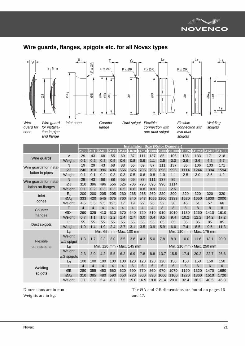
Wire guards, flanges, spigots etc. for all Novax types
Dimensions are in mm.Weights are in kg.
The ØA and ØR dimensions are found on pages 16 and 17.
Installation Size (Rotor Diameter)Ø250 Ø315 Ø400 Ø500 Ø560 Ø630 Ø710 Ø800 Ø900 Ø1000 Ø1120 Ø1250 Ø1400 Ø1600
Wire guardsV 29 43 68 55 69 87 111 137 85 106 133 133 171 218
Weight 0.1 0.2 0.3 0.5 0.6 0.8 0.9 1.1 2.5 3.0 3.6 3.6 4.2 5.7
Wire guards for instal-
lation in pipes
N 19 29 43 68 88 55 69 87 111 137 85 106 133 171ØJ 246 310 396 496 556 626 706 796 896 996 1114 1244 1394 1594
Weight 0.1 0.1 0.2 0.3 0.3 0.5 0.6 0.8 1.0 1.1 2.5 3.0 3.6 4.2
Wire guards for instal-lation on flanges
N 29 43 68 88 55 69 87 111 137 85ØJ 310 396 496 556 626 706 796 896 996 1114
Weight 0.1 0.2 0.3 0.3 0.5 0.6 0.8 0.9 1.1 2.5
Inletcones
E1 200 200 205 205 260 265 265 260 280 300 320 320 320 320ØA1 333 420 545 675 760 840 947 1055 1200 1333 1520 1650 1800 2000
Weight 4.5 5.5 9.5 12.5 17 19 22 26 32 38 45 51 57 66
Counterflanges
T 4 4 4 4 4 4 4 4 8 8 8 8 8 8ØDF 260 325 410 510 570 640 720 810 910 1010 1130 1260 1410 1610
Weight 0.7 1.1 1.5 2.2 2.4 2.7 3.0 3.4 8.5 9.4 10.2 12.2 14.2 17.2
Duct spigotsG 55 55 55 55 55 55 55 55 85 85 85 85 85 85
Weight 1.0 1.4 1.9 2.4 2.7 3.1 3.5 3.9 5.9 6.6 7.4 8.5 9.5 11.3
Flexible
connections
LF Min. 65 mm - Max. 100 mm Min. 110 mm - Max. 175 mmWeight
w.1 spigot1.3 1.7 2.3 3.0 3.5 3.8 4.3 5.0 7.8 8.9 10.0 11.6 13.1 20.0
LF Min. 120 mm - Max. 145 mm Min. 210 mm - Max. 250 mmWeight
w.2 spigots2.3 3.0 4.2 5.5 6.2 6.9 7.8 8.8 13.7 15.5 17.4 20.2 22.7 26.6
Weldingspigots
LS 100 100 100 100 100 120 120 120 120 150 150 150 150 150t 4 4 4 4 4 6 6 6 6 6 6 6 6 6
ØB 280 355 450 560 620 690 770 860 970 1070 1190 1320 1470 1680ØA3 310 385 480 590 650 720 800 890 1000 1100 1220 1360 1510 1720
Weight 3.1 3.9 5.4 6.7 7.5 15.0 16.9 19.0 21.4 29.0 32.4 36.2 40.5 46.3
P x
ØR
P x ØRP x ØRP x ØRP x ØR
ØJ
ØA
1
ØB
ØA
ØB
ØB
ØB
ØD
F
ØB
ØB
ØA
3
Wire guard for cone
Counter flange
Flexible connection with one duct spigot
Duct spigotInlet coneWire guard for installa-tion in pipe and flange
Flexible connection with two duct spigots
Welding spigots
22 Novax
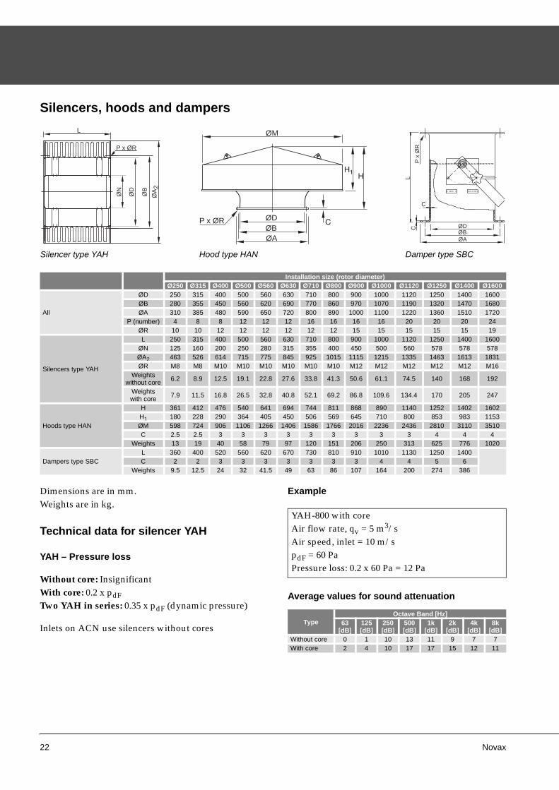
Silencers, hoods and dampers
Dimensions are in mm.Weights are in kg.
Technical data for silencer YAH
YAH – Pressure loss
Without core: InsignificantWith core: 0.2 x pdFTwo YAH in series: 0.35 x pdF (dynamic pressure)
Inlets on ACN use silencers without cores
Example
Average values for sound attenuation
Installation size (rotor diameter)Ø250 Ø315 Ø400 Ø500 Ø560 Ø630 Ø710 Ø800 Ø900 Ø1000 Ø1120 Ø1250 Ø1400 Ø1600
All
ØD 250 315 400 500 560 630 710 800 900 1000 1120 1250 1400 1600ØB 280 355 450 560 620 690 770 860 970 1070 1190 1320 1470 1680ØA 310 385 480 590 650 720 800 890 1000 1100 1220 1360 1510 1720
P (number) 4 8 8 12 12 12 16 16 16 16 20 20 20 24ØR 10 10 12 12 12 12 12 12 15 15 15 15 15 19
Silencers type YAH
L 250 315 400 500 560 630 710 800 900 1000 1120 1250 1400 1600ØN 125 160 200 250 280 315 355 400 450 500 560 578 578 578ØA2 463 526 614 715 775 845 925 1015 1115 1215 1335 1463 1613 1831ØR M8 M8 M10 M10 M10 M10 M10 M10 M12 M12 M12 M12 M12 M16
Weightswithout core 6.2 8.9 12.5 19.1 22.8 27.6 33.8 41.3 50.6 61.1 74.5 140 168 192
Weightswith core 7.9 11.5 16.8 26.5 32.8 40.8 52.1 69.2 86.8 109.6 134.4 170 205 247
Hoods type HAN
H 361 412 476 540 641 694 744 811 868 890 1140 1252 1402 1602H1 180 228 290 364 405 450 506 569 645 710 800 853 983 1153ØM 598 724 906 1106 1266 1406 1586 1766 2016 2236 2436 2810 3110 3510C 2.5 2.5 3 3 3 3 3 3 3 3 3 4 4 4
Weights 13 19 40 58 79 97 120 151 206 250 313 625 776 1020
Dampers type SBCL 360 400 520 560 620 670 730 810 910 1010 1130 1250 1400C 2 2 3 3 3 3 3 3 3 4 4 5 6
Weights 9.5 12.5 24 32 41.5 49 63 86 107 164 200 274 386
P x ØR
ØN
ØD
ØB
ØA
2
ØM
ØD
ØB
ØA
P x ØRØDØBØA
P x
ØR
Silencer type YAH Hood type HAN Damper type SBC
YAH-800 with coreAir flow rate, qv = 5 m3/sAir speed, inlet = 10 m/spdF = 60 PaPressure loss: 0.2 x 60 Pa = 12 Pa
TypeOctave Band [Hz]
63[dB]
125[dB]
250[dB]
500[dB]
1k[dB]
2k[dB]
4k[dB]
8k[dB]
Without core 0 1 10 13 11 9 7 7With core 2 4 10 17 17 15 12 11
Novax 23
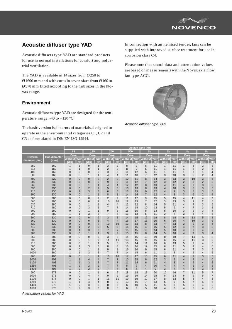
Acoustic diffuser type YAD
Acoustic diffusers type YAD are standard products for use in normal installations for comfort and indus-trial ventilation.
The YAD is available in 14 sizes from Ø250 to Ø1600 mm and with cores in seven sizes from Ø160 to Ø578 mm fitted according to the hub sizes in the No-vax range.
Environment
Acoustic diffusers type YAD are designed for the tem-perature range: -40 to +120 °C.
The basic version is, in terms of materials, designed to operate in the environmental categories C1, C2 and C3 as formulated in DS/EN ISO 12944.
In connection with an itemised tender, fans can be supplied with improved surface treatment for use in corrosion class C4.
Please note that sound data and attenuation values are based on measurements with the Novax axial flow fan type ACG.
Acoustic diffuser type YAD
Octave band [Hz]63 125 250 500 1k 2k 4k 8k
Externaldiameter [mm]
Hub diameter [mm]
Core Core Core Core Core Core Core CoreWithout
[dB]With[dB]
Without[dB]
With[dB]
Without[dB]
With[dB]
Without[dB]
With[dB]
Without[dB]
With[dB]
Without[dB]
With[dB]
Without[dB]
With[dB]
Without[dB]
With[dB]
250315400500
160160160160
1100
1100
0001
1121
2234
2234
881111
991210
5567
11111112
1113
11111110
1113
8876
2212
5544
400500560630710800
230230230230230230
000000
000010
001231
221231
294568
294568
101112131314
111212131314
878897
141213131212
334444
1312111099
324333
1087666
323332
655554
500560630710800900
280280280280280280
000001
000001
001313
221313
2104797
2104787
111212141513
121312141513
978
1085
151214131311
535552
1513119107
434433
1197766
423334
755545
500560630710800900
330330330330330330
000000
000110
000231
232231
3410579
34
10579
141612151515
151713151515
12118
10108
181613151414
864555
181613121010
643444
13109777
533343
865554
5606307108009001000
380380380380380380
000001
000101
011313
221313
3115897
3115897
141315161614
151514161614
139
111296
191516151511
866663
18151311118
745544
14119776
534434
866656
9001000112012501400
403403403403403
01111
01122
14322
14322
107777
107777
17151155
17151498
106644
151211109
63443
118877
44444
77665
34433
56554
90010001120125014001600
578578578578578578
000111
000122
141433
141433
6911888
69
11888
1819191366
18191916109
151412755
201817131110
1088554
161313988
765554
1198766
554544
775655
Attenuation values for YAD
24 Novax
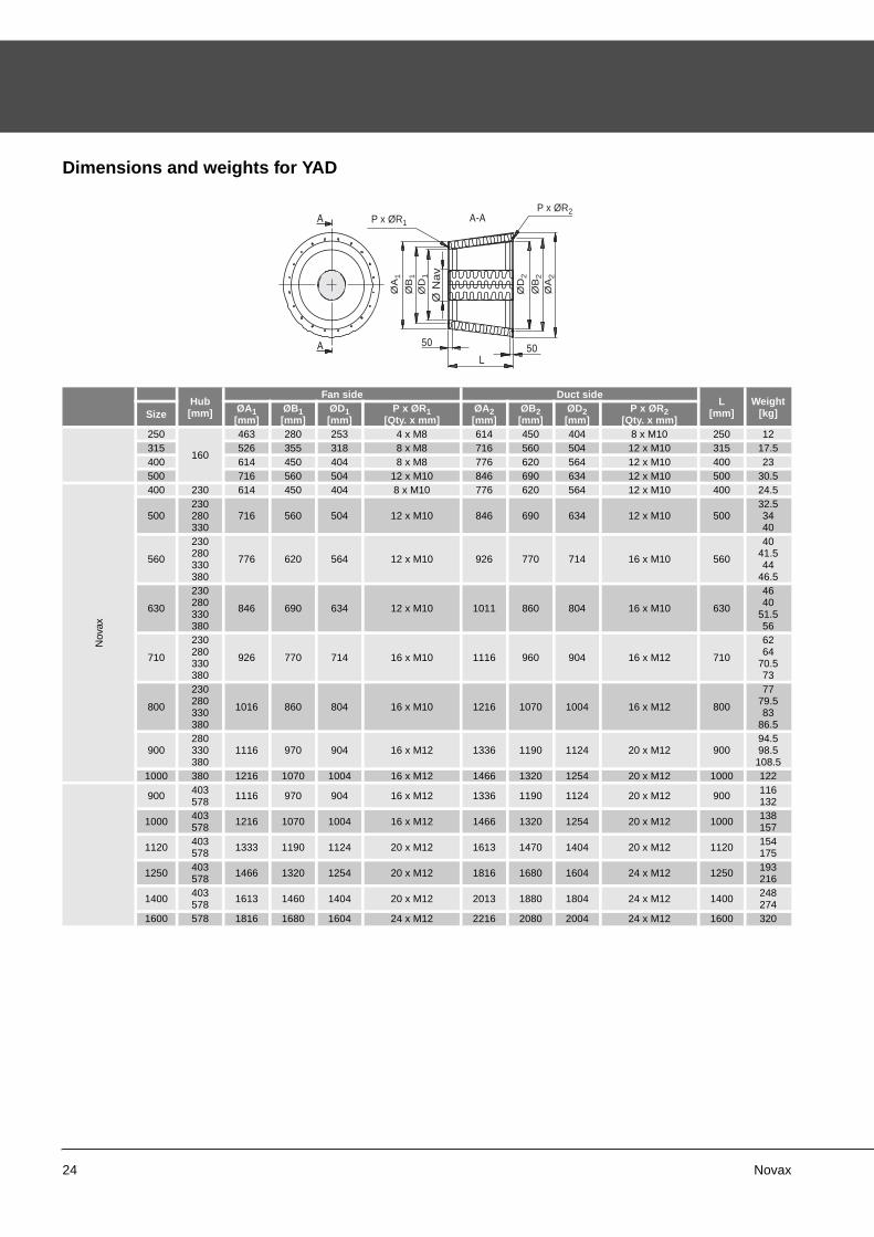
Dimensions and weights for YAD
Hub[mm]
Fan side Duct sideL
[mm]Weight
[kg]Size ØA1[mm]
ØB1[mm]
ØD1[mm]
P x ØR1[Qty. x mm]
ØA2[mm]
ØB2[mm]
ØD2[mm]
P x ØR2[Qty. x mm]
250
160
463 280 253 4 x M8 614 450 404 8 x M10 250 12315 526 355 318 8 x M8 716 560 504 12 x M10 315 17.5400 614 450 404 8 x M8 776 620 564 12 x M10 400 23500 716 560 504 12 x M10 846 690 634 12 x M10 500 30.5
Nov
ax
400 230 614 450 404 8 x M10 776 620 564 12 x M10 400 24.5
500230280330
716 560 504 12 x M10 846 690 634 12 x M10 50032.53440
560
230280330380
776 620 564 12 x M10 926 770 714 16 x M10 560
4041.544
46.5
630
230280330380
846 690 634 12 x M10 1011 860 804 16 x M10 630
4640
51.556
710
230280330380
926 770 714 16 x M10 1116 960 904 16 x M12 710
6264
70.573
800
230280330380
1016 860 804 16 x M10 1216 1070 1004 16 x M12 800
7779.583
86.5
900280330380
1116 970 904 16 x M12 1336 1190 1124 20 x M12 90094.598.5108.5
1000 380 1216 1070 1004 16 x M12 1466 1320 1254 20 x M12 1000 122
900 403578 1116 970 904 16 x M12 1336 1190 1124 20 x M12 900 116
132
1000 403578 1216 1070 1004 16 x M12 1466 1320 1254 20 x M12 1000 138
157
1120 403578 1333 1190 1124 20 x M12 1613 1470 1404 20 x M12 1120 154
175
1250 403578 1466 1320 1254 20 x M12 1816 1680 1604 24 x M12 1250 193
216
1400 403578 1613 1460 1404 20 x M12 2013 1880 1804 24 x M12 1400 248
2741600 578 1816 1680 1604 24 x M12 2216 2080 2004 24 x M12 1600 320
Ø N
av
ØA
1
ØB
1
ØD
1
ØD
2
ØB
2
ØA
2
P x ØR1
P x ØR2
Novax 25
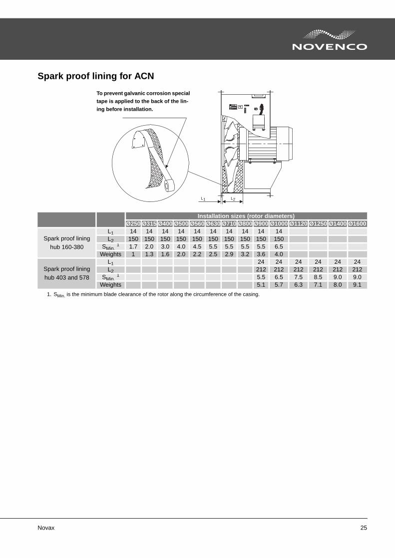
Spark proof lining for ACN
Installation sizes (rotor diameters)Ø250 Ø315 Ø400 Ø500 Ø560 Ø630 Ø710 Ø800 Ø900 Ø1000 Ø1120 Ø1250 Ø1400 Ø1600
Spark proof lininghub 160-380
L1 14 14 14 14 14 14 14 14 14 14L2 150 150 150 150 150 150 150 150 150 150
SMin. 1 1.7 2.0 3.0 4.0 4.5 5.5 5.5 5.5 5.5 6.5
Weights 1 1.3 1.6 2.0 2.2 2.5 2.9 3.2 3.6 4.0
Spark proof lining
hub 403 and 578
L1 24 24 24 24 24 24L2 212 212 212 212 212 212
SMin. 1 5.5 6.5 7.5 8.5 9.0 9.0
Weights 5.1 5.7 6.3 7.1 8.0 9.1
1. SMin. is the minimum blade clearance of the rotor along the circumference of the casing.
L1 L2
To prevent galvanic corrosion special
tape is applied to the back of the lin-
ing before installation.
26 Novax
Calculations
Basis
Novax fans are measured corresponding to the nor-mal installation of the fans. See the following arrange-ments A, B, C and D.
Installing ACN or ACG fans with free outlet (arr. C) causes loss of the entire velocity energy. However, fit-ting a diffuser on the outlet side lowers the outlet ve-locity, whereby some of the dynamic pressure loss is recovered as static pressure. Hence, the energy con-sumption of the fans is reduced. Novenco diffusers are designed to achieve optimal recovery of the dy-namic energy.
a-factor
This is a loss factor, which is used if the fan is used with free outlet (arrangement A and C). The a-factor is related to the speed loss (Δpd) resulting from the dif-ference in air speed between the net inlet area and the total outlet area.
The effect of the a-factor is reduced if a diffuser is mounted on the outlet side.
The AirBox program compensates for the a-factor when the fan outlet is to a duct or as free outlet.
For fans with duct connections on the outlet and oth-erwise unchanged dimensions (arr. B and D) the a-fac-tor is included in the performance data and no correc-tion is necessary.
Examples
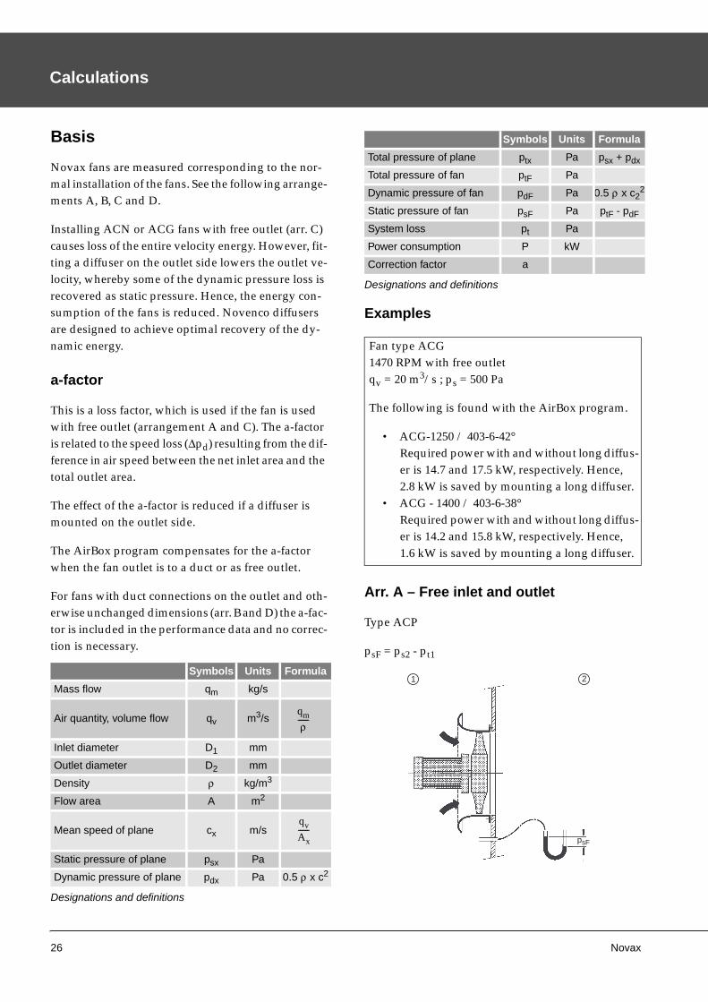
Arr. A – Free inlet and outlet
Type ACP
psF = ps2 - pt1
Symbols Units Formula
Mass flow qm kg/s
Air quantity, volume flow qv m3/s
Inlet diameter D1 mm
Outlet diameter D2 mm
Density ρ kg/m3
Flow area A m2
Mean speed of plane cx m/s
Static pressure of plane psx Pa
Dynamic pressure of plane pdx Pa 0.5 ρ x c2
Designations and definitions
qm
ρ------
qv
Ax------
Total pressure of plane ptx Pa psx + pdx
Total pressure of fan ptF Pa
Dynamic pressure of fan pdF Pa 0.5 ρ x c22
Static pressure of fan psF Pa ptF - pdF
System loss pt Pa
Power consumption P kW
Correction factor a
Fan type ACG1470 RPM with free outletqv = 20 m3/s ; ps = 500 Pa
The following is found with the AirBox program.
• ACG-1250 / 403-6-42°Required power with and without long diffus-er is 14.7 and 17.5 kW, respectively. Hence, 2.8 kW is saved by mounting a long diffuser.
• ACG - 1400 / 403-6-38°Required power with and without long diffus-er is 14.2 and 15.8 kW, respectively. Hence, 1.6 kW is saved by mounting a long diffuser.
Symbols Units Formula
Designations and definitions
psF
1 2
Novax 27
Formulas for pressure
All inlet sizes of the fan are designated by subindex 1 and all outlet sizes by subindex 2.
Arr. B – Free inlet and duct on outlet
Type ACG
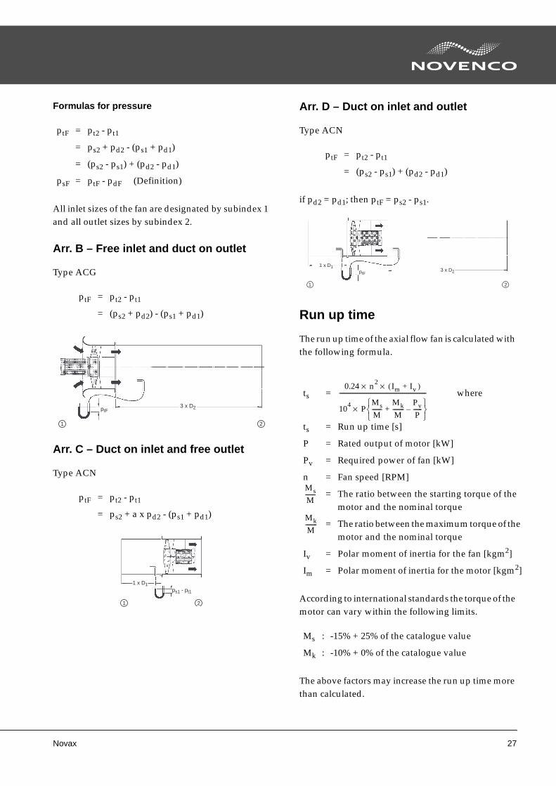
Arr. C – Duct on inlet and free outlet
Type ACN
Arr. D – Duct on inlet and outlet
Type ACN
if pd2 = pd1; then ptF = ps2 - ps1.
Run up time
The run up time of the axial flow fan is calculated with the following formula.
According to international standards the torque of the motor can vary within the following limits.
The above factors may increase the run up time more than calculated.
ptF = pt2 - pt1
= ps2 + pd2 - (ps1 + pd1)
= (ps2 - ps1) + (pd2 - pd1)
psF = ptF - pdF (Definition)
ptF = pt2 - pt1
= (ps2 + pd2) - (ps1 + pd1)
ptF = pt2 - pt1
= ps2 + a x pd2 - (ps1 + pd1)
3 x D2ptF
1 2
1 x D1
ps1 - pt1
1 2
ptF = pt2 - pt1
= (ps2 - ps1) + (pd2 - pd1)
ts = where
ts = Run up time [s]
P = Rated output of motor [kW]
Pv = Required power of fan [kW]
n = Fan speed [RPM]
= The ratio between the starting torque of the motor and the nominal torque
= The ratio between the maximum torque of the motor and the nominal torque
Iv = Polar moment of inertia for the fan [kgm2]
Im = Polar moment of inertia for the motor [kgm2]
Ms : -15% + 25% of the catalogue value
Mk : -10% + 0% of the catalogue value
1 x D1
ptF3 x D2
1 2
0.24 n2 Im Iv )+(××
104 PMsM-------
MkM--------
Pv
P------–+
⎩ ⎭⎨ ⎬⎧ ⎫
×
--------------------------------------------------------------
MsM-------
Mk
M--------
28 Novax
Finding the total efficiency
The total efficiency tells how effective the complete ar-rangement is. The efficiency is found with the follow-ing formula.
η total = η fan x η motor , where
η total : Total efficiency
η fan : Fan efficiency
η motor : Motor efficiency


Novenco A/S · Industrivej 22 · DK-4700 Naestved · Denmark · Tel. +45 70 12 42 22 · Fax +45 55 75 65 50
www.novenco-group.com
MU
14329 0
8.1
0
Novenco develops and manufactures
ventilation and fi re fi ghting systems that
are marketed and distributed world-wide
through subsidiaries and agents.
The company was founded in Denmark
1947 and has become one of the
world-leading suppliers.
Novenco symbolises quality and environ-
mentally friendly products. The company
is certifi ed according to ISO 9001 and
ISO 14001.
The headquarters of Novenco is located
in Naestved, Denmark.
Novenco, Hi-Pres, XFlow and ZerAx are
registered trademarks of Novenco.
Read more about Novenco on the
Internet.