november 1976 vied1stcne - apps.dtic.mil · a^r-senai, alabama 35809 ... none mounted catia~ds is...
TRANSCRIPT

TECHNICAL REPORT RO-.77-8
THE EFFECTIVENESS OF CANARDS FOR ROLL CONTROL
James R. Burt, Jr.
Aeroballistics Directorate
US Army Missile Research, Development and Engineering Laboratory
US Army Missile CommandRedstone Arsenal. Alabama 35809
November 1976
Approved for public release; distribution unlimited.
ft Vied1stcne A^r-senai, Alabama 35809
SMI FORM 1021 1 MAR 66 REPLACE' AMSMI 1021 *NICH MAY Or OSED

DISPOSITION INSTRUCTIONS
DESTROY THIS REPORT WHEN IT IS NO LONGER NEEDED. DO NOTRETURN IT TO THE ORIGINATOR
DISCLAIMER
THE FINDINGS IN THIS REPORT ARE NOT TO BE CONSTRUED AS ANOFFICIAL DEI -%RTMENT OF THE ARMY POSITION UNLESS SO DESIG-NATED BY OTHER AUTHORIZED DOCUMENTS.
TRADE NAMES
USE OF TRADE NAMES OR MANUFACTURERS IN THIS REPORT DOESNOT CONSTITUTE AN OFFICIAL INDORSEMENT OR APPROVAL OFTHE USE OF SUCH COMMERCIAL HARDWARE OR SOFTWARE.
IlI

UNCLASSIFIEDSECURITY CLA3111FICATION OF THI.S PAGE (UR.- t,.,. Pn...d)
REPORT DOCUMENTATION PAGE BEF~ORE COMPLETING IFOPM
"11GVT AsCCESSION No -7PIE..TS CATALOG NUMBER
TH FFECT IVENES S OF CANARDS ..FOR ROLL CO'6NT1flL- Te chnical,~~t
"Ill- rIrNGl 4ORG REPOR NUMER
7.ATNR& CONTRA~CT ORGff U~N mr(.)
P- PERFORMING ORGANIZATION NAME AND ADDRESS 06T RNA6M eLE3ME NT.P O~jECTr. TASK
AR A SIRA
US Army Missile Commuand A 3633AlATN RM-DAMC24S . 511.03
Redstonc Arsenal Ala 35809 ______________
11. CONTOLING OFFICE NAME AND ADDRESSe r NoailiM 761US Army Missile Coriuand F ý SATTN: DRSMI-UR 5
Red ,toan. Arsenal Ala 35809 __________
IAM NTRIN AGENCY NAME A ADDRESS(I1 d11I..ae I-oi C-.t~id.4a Diet-) IS SECURITY CLASS WhiA.-ePonI
UNCLASSIFIED
ISA OECL ASSI FICATI ON/ DOWN GRADINGi SCHEDULE
17. DISTRIBUTION STATEMENT (of the abstract mnIC..dn 81,ek 20,.it dI~fleten frhg, R-*.,f) \jl
ID. SUPPLEMENTA-V NOTES
I- KEY WORDS3 (C~fr-ti.. .1d. It A*46*ay. aud Id-ftII4 by ElayS nwb.,)
Roll controlSmall, nose notinted canardsClipped delta planforinPlanar tail
A study of the roll control effectivne~scof small, none mounted catia~dsis presented. Mach number was varied from 0.6 to 4.5, canard differentialdeflection from -3* to 5 %1 and angle of attack from -3* to 6% The canardswere small with a c~lipped delta planforin and were tested in two longitudinalnose positicns in combination with both a planar tail and a ring tail. Itis show~n' that the effectiveness of small, nose mounted canards as rill controldevices depends upon tail shape
JAM 76 mnow or530 NoF ii iOV oest OSlE UNCLASSIFIED
SECUIRITY CLASSFI1CATION OF THIS PAGE (Wb.- Coto Swwd)

UNCLASSIFIED)89CUmTY CLAISVtCAgN DIP THISPGe~. De*~u~
UNCLASS IFIED
i Itcu fti Tv_ CAsiSrocriYom oF THIS PAGP(P?,I DO'- B,.,.d)

CONTENTS
Pa ge
1. INTRDUICTIO. ...... . 3
11. EXPRIENTAL PROG . . . . . .. . 4
111. DISCUSSION AND KESULTS .. .. ................................
IV. SLWI~ARY AND CONCLUSIONS .. .................................. 10
REFERENCES. .. .. ...... . ........................................... ............
LIST OF SYMBOLS. .. ................................................ 2
INS.
*71i
II-.- aP- - -N A -ROG -, . . . . . . . . . . . . . . . .

I. INTRODUC! ION
Nose mounted canards are attractive candilates for aerodynamiccontrols on a guided missile for Keveral reasons. Generally. the hingrmoments are small compared to those devdlloped by an equally effectivetail control. The effectiveness uf canards increases with increasingangle of attack rather than decreasing as does tail control effective-ness. Also canards miay be employed to tailor the missile stabilitymargin by decreasing the transonic stability hump (1].
A common reqiremnent for a guided missile is that the roll rateshould be maintained at d low level or ever ¶.hat the mitsile should befixed in roll position. One potential advantage of nose mounted canardsis that they may be considercd as roll control devices as well as givingcontrol forces for a manetvering missile. The purpose of this study isto investigate the effectiveness of small, nose mounted canards indeveloping rolling moments for roll attitude and roll rate control.
The aerodynamics properties ot canard-cail configurations arecomplicated by vortices, produced by the canards at incidence, trailingpast the tail panejs and effecting the tail lift. This phenomenon maybe beneficial at times such as by increasing trim angle of attack fora given canard deflection angle or by decreaszng the transonic staticmargin rise, thereby decreasing flight path errors due to windsensitivity.
Theoretical predictions of the aerodynamics of canard-planar tailconfigurations are complicated by the difficulty in estimating correctlythe canard induced vortex strengths and the vortex trajectories as theytrail downstream past tne tail panels. The method of Pitts, Nielsen,and Kaattari (2] was modified to calculate canard ,ortex induced planartail tolling moments but comparison with experimental data was poor;therefore, it was not included in this report.
Wind tunnel data were obtained fot canard-planar tail configurationsr with variable canard longitudinal positions. Mach number was varied
from 0.6 to 4.5 and angle of attack and canard differential deilectionwas varied from -3o tc 50. The data wera obtained from three differenttest facilities.
Some data were obcained for" a canard-ring tail conifigurarion atMach numbers 2.5 and 4.5 with the canards located in only the most attposition. Comparisons are made between the canard-planar tail configur-ations and the canard-ring tail configuration in roll controleffectiveness.
43PP.SLDY!G PAýt t&ioAW.akrFIM
.rv
- - m a - ---- -- --- --.-I I F l l 1-i.- - -. 1 n I .- I 1--.--

II. EXPERIMENTAL PROGRAM
A. TvsL I it C fieL S
The 8-fL transonic wind tunnel , located at CALSI 'NCorpor.ktiuin, bu!lfolo, New York, was used to obtain the data for ,M1ahnumbers o, 0.6 to 1.25. The tunner test u.ction has perforateC wallsand .i iux'lilary pumping syszem for ai tenuation of reflected shock a.d,x'ansiion wuvcs oni models in the low supersuniic range. This method ofattenuattin reflected shock and expansion wa•es is Jescribed in detailir, Refecence J. The closed circuit tunnel is capable of ipeeds fro-M5 ftisez up to Mach number 1.3',. For this t.:srt, the tunnel wasprimarily run "n a constant mass mude which is the most efficient way,timtwise, to operate at several Muich nur'cers. Constant mass mode meinsthati no air Is added to the tunnel in going from one Mach number to._noth.2r. Ir. this node, boti Reyr.olds number and dynamic pressure vary
with Mach number. A photograph of the inLtallation is presented inFijgurc 1.
Vie Anes Research Center 6 ft x 6 t supersonic wind tunnel wasused to obtain dati for Aach numbers 1.5 and 2.0. It is a closed-circuit,single-return, continuous-flow facility and has an 3syu;-metric sliding-block nozzle and a test sactLon with perforated floor and ceiling toperm-t boundary-layer removal. Continuous testing is available for
Nach numbers from 0.25 to 2.25' ith Reynolds numbers trom 1.0 - 10 to
5.0 , 10 6 /fr and a maximum stagnation temrerature of 5800 R. The tunnelair 1! driven by an eight-stage, axial-flow compressor .-owered by twoclti. icik' motors mouttted in tdndem ouLside thv wiJAd vattnel. The Amessting, El 11 235-500, together with a 5' angle adaptor, was used tomount the model. The model was inverted in tie tunnel during all thetests.
The Arnold Engineering Development CettLer, Von Kateoi, Facility,
Tunnel A, was used to obtain data for Mach numbers 2.5, 3.0, and 4.5.Tunnel A is a crntin'tous, clcsed-circuit, variable density wind tunnelwith an automatically driven flexible-plate nozzle and a 40 in. ; 40 in.
b test sectLon. The tunnel can be operated at Macu!. numbers from 1.5to 6.0 zt maxinum stagnation pressures from 29 to 200 psia, respectively,
rl and s,.agnaticn temperatures up Lo 75U0 R (A'. - 6.0). Minimun. operating
pressures rinne f.,am approximately one-tenth to one-twentieth of theSmaximum at each Mach number. The tunnel is equipped with a modelinjection system, whizh allows removal of tht. model from the test section
Lt, thc Lunmi,: ro'nains in operation.
4'4
1 ,*0

1. ýitnd Tunnel Model
]Thu wind tunnel model waF a sting mounted body of ruvolu-Lion, 5.0 in. diamete~r, 52.0 in. lung, and hid a tl.ree calilier Lail.uIl.ugivc. The model body ir shown in Figurc 2. The model was tested withitwo sets of canards, one set of planar tail panels and a ring tail.The model was unique in that all four canards "nd Lail parnels were eachimounted on three component balances along with a six-component mainbalance which raea,:uied total model loads. Each canard was deflectedremotely; the deflection angles were measured by potentiometers mountedon the canard deflection mechanism. The tail panel. e.-e iindeflectcdthroughout the tests.
C. Canards
The two sets of canards had essentially the same plan-foim. These two sets were tested at two different longitudin;lpositions on the model nose with the canard root chord remainingtangent to the model surface at the canard hinge poi.nt. The twolongitudinal positions are shown in Figure 3; the canards are shown
in Figure 4.
D. Tail
A rectangular tail was tested with tho trailing edgeflush with the model base. The tail has an exposed aspect ratio of1.0. A ring tail, designed to give approximately the same Staticstability as the planar tail was tested at Mach numbers 2.5 and 4.0.The vertical support struts were not attached to tie body. With thisarrangement, the two horizontal tail balancea provided measurementsof th_ total force on the ring tail. The tails are shown in Figure 4.
E. Test Conditions
The canard-plandr tail configurations vere tested atMach numbers 0.6, 0.8, 0.9, 1.05, 1.25, 1.5, 2.0, 2.5, 3.0, and 4.5,'while the ring tail configu,:ation was tested only at Mach numbers 2.5and 4.5. The angle of attack was varied from approximacely -3* to 58and the canards were deflected differentialiy from -?* to 5e* Alldata were corrected for sting deflections ana flow angularities.Tunnel operatithg conditions are give:, in Table 1. The main balanceaccuracy was estimated to be 0.5% of fuil sLale fo: each balance gageand the paael balance accuracies were estimated to be on the order ofi% of full scale, where the full scalc loras a'e:
Canard Tail
a, Normal forze (Ib) 40 60
"Root bending mo'ent 35 130
(in.-lb)
Hinge moment (in.-lb) 25 100
5
ai

1AIII| RA -"" 1 C,"!,'-.
Number Rpytw, ld4 No. lu ill,
0i. 8 O.17 50U
0.9 0.18 4.2Q
1.05 0.19 4?90
1.)54 0. 11 550
1. 5 0.20 500
2.0 0.20 5 V)
S5 0.23 547
3.0 0.26 1 547
It wai estimated Oialt atlv ul attack was accurate to -0.0; andcanard deflOcLion arngles tu "0.10'. The basic u4nd tunnel data -irv.
presented in plotted form In Referen,.es .4, 5, and 6. Tlhl, data axisuystem ito shown in Figure 5.
F. Da.tii Reduct ion
Total ind4lbrolling modent i oen'iciert .--.s cculated1trom the canard and tail balance da~a itC, 01P follulwing riner:
C M- + CIlR I B C2 5B B CCR - Cl Cos2 + C .C " o C+ Cc4
-D- (-CNcI CO8A1C, + CNc 2 c 2 +.,Nc 3 coJ C3
-CNc cos 'C4)
C -C CM + C + CT
MT M 1R S B B B1' Ti T2 T3 T4
+ - C N + CN + L'
6

l'L .1* ~ ,, *
III DISCUSSION AND R~ESULTS
A. L.otiari-a-1iI Cvl.; t~urt'iilon Aurudyrnaics
1li, .avrodvii~arnc Oiaracte riotic-i of canard-Liail coixtigura-t. ioiis ltre % omp I ;( b-% iube t. hvt c ina&r dis d -I ; Iti 'Heno. gvier.i te vo rt Ic vsWi' it: tit r1 ; Ii d.'wn't FVai .I'-t. the ta il and % igiý( iC f cant 1y chanige 01 Lo.it ii1i1t. Vortex c ist~v i-.: s , u-,h ;% nui-ioer of vurt ici's , strQ1ngci,pos it I mi, andt tyre ýkrv kul ten !if ( ictuh tv predict. anatlyt lccii I Y . Atmtodvratt! angles of ut'tack. Lith body may ~vcfl generate SyVnmott'iCUl oruvnsymmetrik l.. Vknir~ies Which change the flow f ied about the Lailparilsl dL'd aflIct~ ta.il lift. Spahr rnd Dickey (71 have shomi thatIthe 4etwerry of- tho wit',e .iL it leavos the caiu~rd or wing varieslion~ider.ably with .canat d aspect ratioa .nd angle of attack. The vcrtexsheoit generated 11, low aspect. ratio canard with %labsonic, leading edgetends to roll ulp into a .iingic vor-t'x ahc~d of the traiiing edge;lic~wever, the vortex~ ivke ge~nerated hy a large aspect ratio canard at:iargc u&L~gltŽ of -Attack and with a supersouic leading edge may Ieavethe traiiing edge its a vo&czex sheet Oiich rolls up into two vorticesat Slone poin,. doum'strearn cl the canard. The fG1lowing sketch shows
I.AC
N~fi-

-- - -----
'1hle carlnirds used iii L ii Is zii.' es t .lgit tot ai 'll thad s -t:I soni I C: Itaanti th ICvt I Ivs of v4apo1t. stEf 'vint 1,ographis inIi I gmrt' Cr Slhows t 11.1 C tnt
vur t#cx is sliud I rom etchi cantiord iand appjeair,, to Uti': j c t-,ipIvt ]) i. Ic-uup ats it 1 caves t ivt' an a ra d t ra i 1 I g edge. I tic -.c : I is ul v~i,'r sc: It
pliotographsu were takeni -t anil anglfo of al'.t~i ci 12", SO IC. hat)i VýII)qfur thle hotly indoccd votV ticuis to be gene rat. d ais sts'wii inl tic 'Ii~o~.tm:ri;'!,-
B. Uhserv;U itloiw I rumi EX1'cr Inicrial Diatai
Wind tunnel. t4.:sts were conducted Iii wt1 cl ca~la i'jti, t c s idcanards wecre duf lct. td di 111er.-it tally over thec rarigt -3' to 5' soc, thaeacti canardl prodaced a rr. ii big moment In thle S art dl rotL it 'll Iom t ti
model cciiterltilie. Angi~le of- acmnck was, var iet It. twecri -36 adi 5' Atvacti canard and Maclh number condition.
C. Planar Tail
ri1gurvs; 7 throughli, 24Sh'.0' .- l ing nOr~le,i cotlfr it. lit. -Pa f uric tir. (t 'hi cli iinumbr and anglIe of atr.IC :ic V'r a coast.itt S V di ffe r -
cnt lal canard deflect ion' w,.tti the canard% :ii die forw~ard ai~d aftposit ion. These plots show the r ol1 liii fliornnit c''tI I ic tent dvcn;'ej
by d-iv canards only v dtiv ta .iiJs-n mv . anid Oir LtJirilards 'ustil U:. tt1 1-LOAl
roll itig moncaet I ItCic cL't) . IoUta 1 nIl I lagý mo-c at co'r t. I ,vlnt. r;,ca urcivi
directly hiorn ., ucivodel ma in balaknce! is a) s s- ii arid gciiBcurý-pares very well wi th thev value~s compoted I roti c.anard and tall I alazn: s
The mi-st notable aspvct of tl.t: p1 an.,r to.il c t'ris2 ,gorat Ion dat aIsthit. whilie tie rolli[ag miorien t -love]0td 'IN' ci\tlt'hc Ctial ¾Is 1i argt' Ml
that developý,d "~v the tail is lirge * the suntirmed railing mnomeit. Coolt-fictont is snail beCcause the direction oir :ign ofl thme cinardI andl taillvalue's are difler'nt . Theo- c usartl roll iip- "-oenwnt ;cf].t~~*~~ gtim-o ratetl by the devi trcftuin aug IQ Of tOW' !our .tna ris; liowevczr, t ho Ldaitrolling moment cacIflic.ictirts are caused by ih" xorf lazs. * sed by L!Iv.tleflcred c~llartS, * trailing paist rime tail p-antls an).. inducizlg air cr It-
tLyeq angle of at tack for each tatii panel. lT'e caniard rolliA lag srtu-ntare' gencrall1v large r than the tail Io 1 11Ig momnk-1ts- it) I Lic i C C1t.; ,l'ui
at tlio supersonic Macht numbers,* the tatil moment nay lIt lairger Cian tflt
c an ard momncti:. I n thIi s cas e * 0c1ic re s u11 ten mo men t isý illOl thy cPUmo, ILt'directio-n than would be logically'N eXpc':Ied WIi~i tic' Viveml c-lanad t!h: It-.tion. 711iis phlenomenon hjas been termed ridll revel sal and is ee t:u!:the panel data at Macli aurubers 1.05 anld 2.0 vit'; the cana~rds tinl tiv
b fowvard posit ion and Macli nuntet s 1.5 S itiotim .? w il'ii the ca'rardsz illthe ai\ posit ion. No data were obtained for thet forward caiia-rl l!in
tions at Macli rurumter' 4.5. Roll rteversal lhas been ot'scrvee rtlusliii wind tunniel tests of models w~tln large canards beat 1ýd onl Ott. ,..an
body diameter as8 the planar tail.
Tot~al rolling miumnti ot.'e ficilent f run i'l 01V d i. i ti nplanar tail cornfigtirat oi.n is shown p)lotted 01n .i11 eX~ldndcd scale it,
itFigures 25 through 42. At times, sizeable2 rolling moments were -ceni

the datw when all ftyUr •Anards wtre undefiectidi thuse 9*amnts wotrdsubtracted fn e tit dat, !or 4etlouted gzaards. This type of datacorrectiLon tsa vaifactory if the too deflection wnis reptsoesra constant "as LIn the data; hb•wevor,. t•is data odjustmiw isa hut
cortrect If the atoe doflaction Pament% are due tc a caAted detlectonbids error. A coawtant canard or tAti ddflk'tton bias error wouldcreate a nrnlnotr error &i rlling mnt.
'the expared scale roiling *.ent dita are shown plottea for thaforward and aft moumtoad canard oafig~gutstion thr~vhoit the canarddeflection and Mach number range. The data are gerntral.y not eymetralAbout taro hngle of attack at would bt expected fcr tht configurationstested. The reason for this asysetry is (tot knon; however, Figures7 through 42 ithwng tt- roll lil woment cowponent data indicate thatthe aaym.etrr to due to the tail comporent rather then the canardeoaponent. A slight staliitment of on. or more of the tall panelsmAy be the culprit; because, ad previously stated, error* due to panelmisalilgrant would be nonlinear with angle of attack. The rclling*antse arte gonarlly -n the expecttd direction 6;4boonically endtransonically, but in the supemsonic Mach number rarne, the tellingtmeunts are in rho reverse direction than would be expected for bothth" configuratlons tested. The reason for this is not known other than%.he physical fact that the :64"nent of rolling woment due to the tailpanels .'s larger than the (--ponont du. to the canards. Roll reversalis clearly shtvn in figure 43 for aero angle of attack and differentialcanard deflections of 5t.
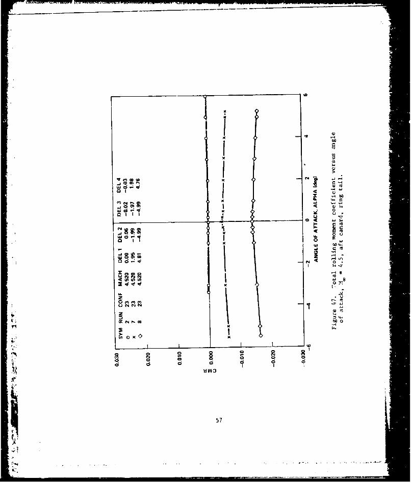
D. filn Tail
Figures 44 and 45 show rolli..g msaent coefficients Lurthe :in& tail configuration as calculsied from the canart balanc*-salone, h•. tail alone, the canard-tail balance combination, and themain blance. These figures thow that the ri,)p tail, unlike tho planartail, does rot develop large induced rolling moments it the Mach numbers
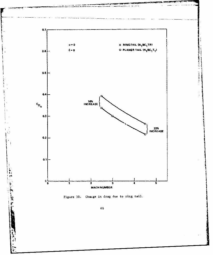
b tented. because of this fact, small canards in rjobtnatton with a ringtail appear to be tar more effective as a mians of roll control than"small canards in line wat, an equivalent planar tail. Variation ofrolling moment coefficient from the uAin balance as a function of angleof attack and ciiard deflectLot angle for the ring tail configurationis shown in Fidures 46 and 47. Rolling woment coef(itient for tho ringtail configuration is a linear function of canard differential deflec-tion ane does not vary with angle of attack as do*& the planar tailcon•iguration over the pdraimeter ranges tested. A coaparison ofrolling wom-?nts from the planar tall and ring tail are shown inFigures 48 and 49. The rlflU tall configuration (;us* hava the possibledisadvantage of increasing the missile drAs from that of a planar tailconfiguration with approximately the same characteristi%s. The dragincrease Is sl'uatn in Figure 50.
I9
IV. SUMMARY AND CONCLUSIONS
This report is a study of effectiveness of small nobe mountedcanards as roll control devices, moderate canard deflection angle, andsmall angles of attack. Wind tunnel data were obtained for canards intwo different longitudinal positions. Mach number was varied from 0.6to 4.5, canard differential deflection angle from -3* to 5%, and angleof attack from -3* to 6°.
The following conclusions were drawn from this study. Small, nosemounted canards in combination with an in-line planar tail are noteffective as roll control devices unless decoupled froyr the tail panelsbecause the vortex induced tail rolling moments are of the sane magni-tude as the rolling moments developed by the canards alone. The netrolling moments are generally only approximately 10% as large'as therolling moments developed by the canards alone. In the supersonicMach number range, the tail component of rolling moments may actuallyhe larger than the canard component, Pnd in the opposite direction,leading to the condition known as roll reversal.
Small, nose mounted canards in combination with a ring tail,however, show promise as roll control de-ices because the canardinduced vortices do not cause any significant tail rolling moments.A ring tail giving approximately the same stability characteristicsas a planar tail does, however, cause some increase in total missiledrag.
IL is recommended that further wind tunnel teSt, be conducted inthe subsonic ant transonic Mach number range to supplement the rathersmall amount of canard-ring tail configuration data available. Varia-tions in ring tail planform and mounting strut design should be includedin these tests.
10
I -II
___ _ __

V
'aI,,"I
C-4
-4ci
-nC
-4
C)
C-
1FJ!I�1.4
S S
11
S

U)
IX I
Li0
Co
w. 0
0
LU1
r-4
z oo
2 > 00S0
o
z4 u 000 CC 0
u 5z
•...
Oz
zJ 4 C4
00
-Iw
12

'AA
49
2jo
- o
1. .4
4
)o a4
ant
'-4
131

K •- HINGE LINE0.015 R TYPF I TflLE AND TE
2.48 060 0.03TYP - TYP
1t. 250 -73.7 1.51
4700- TYP {E OO TYP
MS 52.00 01
- P 2. -100 .667 JI .< 7 0.01S R T. P I - 'YP
TYP
PLANAR TAIL PANEL CANARD PANEL
SECTION A-A
150-Y) 0.01 R (TYP) 0 125I1SOO' ITYP) --• •_
THICKNESS VARIES FROM 0.02 TO 0.125
A r ,A
MISSILE
BODY
I,L
0 2-0 BALANCE-SUPFORTED STRUTS
900. 4. NOTE: VERTICAL STRUTS ARE NOT ATTACHED
MS 52.00 TO THE MISSILE BODY.
ALL LINEAR ARE DIMENSIONS IN INCHES;NOT TO SCALE
RING TAIL
Figure 4. Planar tail, ring tail, and canard panel.
114
rl•,It .

CNC CN VIW C C4CN T NIV C NT
VIW
-LOOKING - LOOKINGFORWARD FORWARD
CNC3
CANARDS TAIL FINS
/ I I• -iCNc4 CN CM4c 4
* CNTCNT 2ý
CMF POSITIVE CLOCKWISE LOOKING FORWARD
Figure 5. Axis system and positive sign convention (typical).
15
A

44
0 - (000
4 -r
16.

SYM RUN COWP MACH DELTAI OF.LTA2 DELTA3 DELTA4
a 776 CANARD 0.60 5.06 -5.13 -4.06 &W0
S778 TAIL 0.60 6 C, -5.13 -5.06 S.00
776 CAN-TL 0.60 5.06 -513 -5.06 1.00
0 770 MAIN 0.60 &06 -5.13 -5.06 IL00
0-08 T NOTE: DP.LTAS PERTAIN TO
CANANDSONLY
0.06 1
TAIL COMPONENT
0.0
Uji
CANARD COMPONENT
ANGLE OF ATTACK
Figure 7. Component rolling moment coeffic'ent,MW- 0.6. forward canards, planar tail.
17

RM U COW MACH DELTA I DELTA DCLTA3 DiLTA40 757 CANARD 0aft0 A-5.13
-, ,014 5?7 "At 0 606 -(Aft
4 l.01a 57 CAN-TL 060 &-.13 -&060' ) 7 M A IN CLOD t ooi0 - 5 ,-13 - 6-041 0
0.04 -- 0 &01
-fPANEL ABALOANF$
0-cpa-0.0.CANARD COWIONENT
S~-006.
t - 0 .0 4
t ANGLE OF ATTACKS •"Figure
8. Componeat rollitig moment coefficient,0= -08s forward canards* planar tail.,
18
A
nea---

"SYM RUN COMP MACH DELTA I DELTA 2 DELTA3 DELTA4@ 701 CANARD 0.90 L06 -LI1 -5,05 5.02A 701 TAIL 0.90 506 -,11 -5.05 5.02x 701 CAN-TL 0.e0 506 -LOG -5.05 &02O 701 MAIN 0.90 5,06 -511 -LS0• , 02
0.08
0.06TAIL COMPONENT
0.04'
0.02
PANEL BALANCES
-4 -2
EE -0.02
CANARC SAL ANCE$
I,
S~ANGLIE OF ATTACK
t• Figure 9. Componert rollins uoment coefficient,I • ~H - 0.9, forw~ard canards, planar tail.
•-0
-00
-mw-- - w ~~-0.0 --.

3vM NUN COJMP MACH4 OELTAI Of' 1A2 DELTA 3 DELTA 4e) 670 CANARD 1.25 LO07 -15,12 -SOS &.0140 670 1AIL 1.05 L07 -1.12 -606 5&01
1 670 CAN-TI 1.06 5L07 -6.12 -5.05 &01C 67G MAIN 1.06 6.07 -5,12 -606 &.01
TAIL COMPONENT
IL0 PANEL BALANCES
CANARD COMPONENT
ANGOLE OF Al TACK
Figure 10. Comrponeat tolling~ momrent coefficient,Mw, 1 .05, fo4ward canards, planar tail.
20

gym RUN COW* MACH DILTAI1 DIELTAI DILTAS D§LTrA4
a 651 CANARD 1.2% to$ -&11 -500 1.00
S 31 TAIL 1.21 &06 -V12 -t4.0 50
TAIL C016 11NSN¥
0.02
S;- • t _•, ,o~oT't-- C •* 'ONoj
• •pax." PANEL ItLANC-S
II
-0.02-
-IX04
CANARD COMPONENT
ANGLE OF ATTACK
Figure 11. Component rolling moment coefficient,
M , 1.25, fot,4ard canards, planar tail.
21
- -. -, "-

SYM RUN •,MP MACH DELTA 1 %OTA 2 R LTA40 46= 1.50 4.90 .950 43 TAIL 1.50 -4.95 5.04 -4.96 &04M 43 CAN-TL 1.50 -4.9S 604 -4.95 &040 463 MAIN 1 .50 -4-9b b.04 -4.96 &040604--
0.06°
TAIL COMPONENT
MPANE BALANCES
711
CANARD COMPONENT
"• ~-0-0 --
-0.0
ANGLE OF ATTACK
Figure 12. Component roll1ia moment coefficient,* - 1.5, forward canards, planar tail.
22

SYM RUN r.OMP MACH 04LTAI DELTA1 2 DOLTA 3 DELTA40 417 CANARD 1 H 4.V4 -500 -4.9 06s4 457 TAIL 1 06 -4." &06 -4 1 101x 457 CFIN-TL 1." -4.95 t0o -4.16 105Q 467 MAIN I." -496 US0 -495 L06
008 -
0,04--
0.04
TAIL COMPONENT
iMAIN BALANCE
--
w
-0.02 PANCL SAL ANCES--
b -0.04
CANARD COMPONENT
-0.06-
"-0.08SANGLE OF ATTACK
Figure 13. Component rolling moment coefficient,. - 2.0, forwird canards, planar tail.
23
-. --- .--. ..-- - --- -

SYM RUN COMP MACH DEL.TA 1 DELTA 2 DELTA 3 DELTA 40 242 CANARD 3,01 5.01 -&0O1 -4.99 5,02a 242 TAIL 3.01 5.01 -5.01 -4.99 5.02x 242 CAN-TI 3.01 5.01 -5.01 -4.99 b602
C 242 MAIN 3.01 6.01 -5.01 -4.99 %020.08 j
0.06-
0.04-ITAIL COMPONENT
0-0
0.02
U.U-
0 O XX.XV-j ~2 4 6
Uj 4 -2PANEL BALANCES
Zx
0
CANARD COMPONENT
-0.04-
-0.06--0.061
ANGLE OF ATTACK
Figure 14. Component rolling moment coefficient,N=3.0, forward canards, plý2nar tail.1
24

SYM RUN COMP MACH DELTA1 DELTA2 DELTA3 DELTA4o 106 CANARD 0.60 4.99 -5.07 -5.04 4.990 105 TAI L 0660 4.99 -5.07 -5.04 4.99x 10⁶ CAN-TL 0.60 4.99 -5.07 -5.04 4.990 105 MAIN 0.60 4.99 -5.07 -5.04 4.990.08
TAIL COMPONENT
I0.04
0.02
2
tLU.S2 4 6
PANEL BALANCES
aE MAIN BALANCES
[z -0o0 o2-0.06
.J
-0.04
•':CANARD COMONN
-0.081
ANGLE OF ATTACKFigure 15. Component rolling moment coefficient,
W = 0.6, aft canards, planar tail.
25
: -. -

SYM RUN COMP MACH4 DELTA 1 DELTA 2 DELTA 3 DELTA 4
0 59 CANARD 0.80 5602 -5.07 -6.03 5L000 59 TAI L 0.80 IL02 -&.07 -6.03 &00Ix 59 CAN-TI 0.80 5L02 -5.07 -5.03 &.00
0 59 MAIN 0.30 &02 -r%07 -5&03 &.00
TAIL COMPONENT
0.04--i
0.02-
0NEC
U01 ___00
z - -::5MI AAC
-0.04 Iri CANARD BALANCES
-0.08
ANGLE OF ATTACKFigure 16- Component rolling moment coefficient,
N=0.8, aft canards, planar tail.
26
W-M NJ

to.
SYM HUN COMP MACH DELTA 1 0 A 2 D 3 DELTA 40 CANARD 0.90 &00 - - 3 4.9
TAIL :5.02 4.CAN-TL & it HS &O480 MAIN 0.90 %00 -5.02 4."
TAIL COMPONENT
0.04-
I-
0.0
"-. PANEL BALANCES
0
g• _______ MAIN BALANCE
Ixx
"•~06 -o.0-
--0.06- CANARD COMPONENT
-0.08
ANGLE OF ATTACK
Figure 17. Component rolling moment coefficient,
MW 0.9, aft canards, planar tail.
27
I.

SYM RUN COMP MACH DELTAI DELTA2 DELTA3 DELTA479 CANARD 1:81 k.99 -5.06 -Lot 5.o079 TAIL 1 -0 -79 CAN-TL 1.5 -5 -501 J79 MAIN 105 4.99 &05 -Sl 5•00
TAIL COMPONENT
I-0
0.02-
PANEL BALANCES
z-J
0-J
I._
I; MAIN BALANCE
-0004-
'k, -0.08
ANGLE OF ATTACK
Figure 18. Component rolling moment coefficient,= 1.05, aft canards, planar tail.
28
7-3

SYM RUN COMP MACH DELTA1 OELTA2 DELTA3 DELTA40 65 CANARD 1.26 4.99 -1 0
CAN-TL 1.25 4,99 - -6.01 s1aoMAN 1.26 4,99 -4.99 -5.01 &00
0 66 MAIN 1.26 499 -4.99 -6.01 &0oo0.06
4,06-- TAIL COMPONENT
0.04-
I- 0.02
U.U.
S:I I I I I ', -4 - 2 4 6
;IPA`NEL BALANCES
b.
4 -CANA RD COMPONENT
ANGLE OF ATTACK
Figure 19. Component rolling moment coefficient,MM- 1.25, aft canards, planar tail.
29

SYM RUN COMP MACH DELTA1 DELTA, DELTA3 DELTA4CANARD 1.50 4.7 -41 -0O 4STA iL 1.50 4.57 -4 -02CaM-, 4.7 -49 -02 4.96AiN 487 -4.96 -&01 4.96
TAIL COMPONENT
PANEL BALANCESU. x
bz
rA o, -2 2,,__
MAIN BALANCE
-. J-0.02-'--0
-0,04 .. •
CANARD COMPONENT
S.• ~-0.06..--
ANGLE OF ATTACK
Figure 20. Component rolling moment coefficient,M- 1.5, aft canards, planar tall.
30

SYM RUN COMP MACH DELTAI DELTA2 DELTA3 DELTA4
A ý ANARD 2.0 4.66 -4.95 -Lai 4.97j TAI 2.0 -O 4.7 -50 4~
x 60 CAN1-T 8' US 47 603 47<) 00 MAIN 2.00 -5,0 4.97 -6,03 4.97
0.03-
406-.
TAIL COMPONENT
0.04-
Ur.t-CL02-
uI
S~PANEL BALANCES
+" -4 -22 4 6
MAIN BALANCE4.,
- -0.02o
CANARD COMPONENT
_ -0.04
Yi
-0.06--
-0.08
ANGLE OF ATTACK
Figure 21. Component rolling moment coefficient,
MW- 2.0, aft canards, planar tail.
31
AI

ISYM RUN COMP MACH DELTA1 DELTA2 LLTA3 DIELTA4
190 CANARD - -02 L01gAN-I
it160 TL -I
0 IGO MAI N t.oo -&0of0
0116
I0.044
TAIL BALANCES
o.02I-
0LU
2o 0
E PACNAEL BALANCES
I GOI -" 1
-J ANR BALANCES
ANL CANARDAC
-o ;: -. o .
I."
*' ANGLE OF ATTACK
Figure 22. Component rolling moment coefficient,MW 2.5, aft canards, planar tail.
32
; ->

SYM RUN COMP MACH DELTA1 DELTA2 DELTA3 0ELTA4$A-411 14.71"
CAIARD &.0 4.31 Lt -0 4.7T CAN-IL 48 1 1 - 4.714 MAIN 4.81 4.7
O0lS -
004
TAIL BALANCES
SA/ MAIN BALANCE
-Q102- PANEL BALANCES
7j
CANARD BALANCES
8 - 6 Os
' -0 08
ANGLE OF ATTACK
Figure 23. Component rolling moment coefficient,
M = 3.0, aft canards, planar tail.
33

SY ~NCANAR LuC DELTA I DELTAI DELTAS DILTA4'o W TAIL~D45 4831 -1602 -411 4.79~~ U TAIL 4.61 .?2-4I .aCAN...L 4.6" 4.3 -L02 -4 W0 4.7*o * MAIN 4021 4.31 -1602 -Aft
0.06
Q020
PANEL ~ o BAANE rFFIERE
b
-0.03
Figur 24.ANGLE OF ATTACKFiue 4 Component rolling moment coefficient,41 -45, aft canards, Planar tail.
34

SYM RUN CONFIG MACH DILTAI 14LTA2 DELTA) DILTA4o 707 0.00 -300 &00 100 -&006 M FORWARD0.U 0,00 00 000 k 004LOx 770 0.00 M10 -0650 -0LO 0.600 772 CANARDI 0,00 1.00 -1.00 -1.00 1.00o 774 0600 zoo -. 00 -200 2.000 77 0.00 LO0 -LO0 -0.00 &.00
06012
14 01 6,0
I-,-3 2
V
up -0.004
-. 1012
"ANGLE OF ATTACK
Figure 25. Total rolling moment coefficient, M - 0.6,forward canards, planar tail.
35
II - I I I• -" I I I, • I

SYM RUN CONFICi MACH DELTAI DILTA2 DELTA3 DELTA4o 741 0.10 -&00 300 100 -3.006 749 FORWARD 0.,0 0.00 0.00 0.00 0.00* 751 0.10 1.50 -0,60 -0.90 0,50O ?3 t.ANAROS f.1 0 1.00 -1.00 -1.00 1.00
o 755 (Leo 2.00 -o00 -Loa .000 757 also ILO -&00 -5.00 &00
0.012-
0o006
0U00
I -.CC =5
5ANGLE OF ATIACK
Figure 2, Total rolling moment coefficient.
M. 0.8. forward canards, planar tail.
36
.4-'
i- ....- -- -

SYM RUN CONFIG MACH DELTA1 OELTA2 OELTA3 DFLTA4o 092 0690 -100 3.00 3.00 -1000 093 FORWAPD 0,90 0.00 0.00 0.00 0.00- 096 0.90 0.0o -0.10 -0.60 0.500 097 CANAROS 0690 1 00 -1.00 -1.00 1.00
o 6"0 0690 2.00 -2.00 -2.00 2.00o 7o0 0.90 LOO -LOO -&,00 o IO
0.012
0600e
0.004
2
-4-2 2 4 6
z -0.004
2
o -0.008
b
-0012
ANGLE OF ATTACK
Figure 27 Tocal rolling moment coefficient,
M, - 0 9, forward canards, planar tail.
I37
'm' 37
: -- .-

SYM RUN CONFIG MACH DELTAI DELTA2 DELTA3 DELTA4
0 669 1.05 -3.00 3.00 3.00 -3-00S670 FORWARD 1.05 0.00 0,00 0.00 0.00
x 672 CANARCS i.05 0.50 -0.50 -0.50 0.50
e 674 1.05 1.00 -1.00 -1.00 1.00o 676 1.05 2,00 -2.00 -200 zooa 67n 1.05 5.00 -5.00 -5.00 5.00
0.012-
Uii
u
z 01008-
-- 3
I-
LLL
0 -2 2l 4. 61
- 0-
0
e ANGLE OF ATTACK
Figure 28. Tot.al rolling moment coefficient,
S.N = 1.05, forward canards, planar tail.
38

0 643 FORWARD 1.25 0.00 0.00 0.00 0.00
0 647 CANARDS 1.25 100 -1.00 -. 0 1
691.25 -300 -200 32.00 -. 00
0.008-LJ
41
0wo
-3
0
r'i Ix 2ANLzFATC
Fiur 29xoa oln oetcefcet0.004Iz .5 owr aadpaa al
03
M
_M08-

SYM RUN CONFIG MACH DELTA1 DELTA2 DELTA3 DELTA4S 459 O 1.50 -3.03 3.01 3.04 -3.046FORWARD 1.51 0.03 0.00 0.05 0.01
x 460 CNRS 1.50 0.010 460 1.50 0.52 -051 -0.45 0.51S 46 CANARDS 1.50 0.96 -1.03 -0.94 0.99
o 462 1.50 1.97 -2.00 -1.92 1.98
o 463 1.50 4.38 -5.02 -4.95 5.04
0.012
0.008
wzI-
U.F,
z5 0
z_ 022
00
2I-3t,2
4-
_j-
0--
".. ~Figure 30. Total rolling rnomen coefficient,•"•H= l,5, forward caadplanar tail.I7
"040
- -02"---
"401
A'.4
-

SY RU4 C o2I M A CH D E L TA , I T A0 5 FORWARD 1.99 -3.03 30EA2 DIELTA3 OELTA4x 441.99 0.05 -0.01 3.070 455 CANARDS 1-99 0.53 -0.501 0.06 -300 461.99 0 -. 0 04 0.060o 5 1. 29 1.99 -1.02 - . 3 0.541.9 1 .9 -1.99 -0.93 1.010.012 4.99 -00 -1.92 1.98-. o -4.95 5.05
0.008
0.004
0-2
I0.
ANG E O0A0 AC
F~gu~ ~ To~a1 olai g n on20,j f r a d ' 3 lrsa
-0.008ie
415

0 M
$4
D fn
LU
a1 I I
zI- 1-
z
0 U0
0
(4 R 04
o x1'
d - n
2 I2
.. .............

SYM RUN CONFIG MACH DELTA 1 DELTA2 DELTA3 DELTA4
0 101 AFT 0.60 -300 3.00 3.00 -3.00
0 102 0.60 0.60 -0.50 -0.60 0.50
103 0.60 1.00 -1.00 -1.00 1.00
( 104 CANARDS 0.60 2.00 -2.00 -2.00 2.00
0 106 0.60 5.00 -5.00 -5.00 &.O0
0.012
0.008
I-
-. 004
bz
2-0.012
S~~~~ANGLE OF ATTACK '••- -
Figure 33. Total rolling moment coefficient, 0.6 0.6
,•,: ~aft canards, planar tail. I..
43
0F

SYM RUN CONFIG MACH DELTA1 DELTA2 DELTA3 DELTA40 60 AFT 0.80 -3.00 3,00 300 -. 00"" 6 0.80 0.50 -0.50 -0.60 0.500 CANARDS 0.80 1.00 -1.00 -1.00 1.000.80 5.00 -5.00 -5.00 5.00
0.012
0.008LU
616 1
2
2- -3 -3U 0.5 24
:4
U.
x
w
I• -0.004-.j
.
-a-
0
-0.008
-0.012
ANGLE OF ATTACK
Figure 34. Total rolling moment coefficient,SM 0.8, 9ft canards, planar tail.
44
A,' +

SYM RUN CONFIG •IN DELTAI DELTA2 DELTA3 DELTA40 84 AFT 0. -3.00 moo 3.00 -&004 83 0.90 0.50 -0.50 -0.50 0}.50
82 C ANARDS 0`90 100 -1.00 -1.00 1.000 011.90 2.00 -O -2.00 -Zo zo0 OD) 0.90 &,00 -&,00 -5.00 5.00 -
0.012
0.008
' 'UUj
|r -- 0 ,004 -61
81 -3
3 0o 4 -
.2
z!
i " 0
;K ANGLE OF ATTACK
! •. Figure 45. Total rolling moment coefficient,•. •. - 0.9, .ft canard, planar tai,,.
i' ~45
0' :
-0.01

I
SYM RUN CONFIG MACH DELTA I DELTA 2 DELTA3 DELTA40 75 AFT 1.06 -3.00 3.00 300 -3.00A 78 CANARDS 1.05 0.50 -0.50 -0.50 0.5077 1.05 1.00 -1.00 -1.00 1.00S 79 1.0S &00 -5.00 -5.00 5.00
-0.012.
0.008
S61-30• , -3•
z
LU
- 0.5.2 6
.),
-O00
06100
ANGLE OF ATTACKFigure 36. Total rolling moment coefficie~nt,
MIX 1.05, aft canards, planar tail.
46
I77 777

SYM RUN CONFIG MACH DELTA I DELTA 2 DELTA3 DELTA4O 6L AFT 1125 -3.00 300 300 -&00a 62 CANARDS 1.24 0.50 -0.50 -0560 0.50x 63 1.25 1.00 -1.00 -1.00 1.000 64 1.25 2,00 -2.00 -z.00 2.00o 65 125 L00 -LOO -&00 L.00
0.012
0.000
-3 16
-3
z A__ _ _ _ _ _ _S_4 -2••.j 2 4
x 2
2
0l4
ANGLE OF ATTACK
Figu-' 1'1. Total rolling moment coefficient,ýft 1.25, aft canards, planar tail.
f47
• 4?
Ilp r -

SYM RUN CONFIG MACH OELTAI DILTA2 DELTA3 DELTA40 49 AFT 1.O0 -3.08 X.9 2.99 -3&11& I1 CANARDS 1.50 -005 -0.02 -0.06 -0.0?x 53 1.50 0.43 -0,47 -0.40 0.430 55 1.50 0.91 -0.93 -1.01 0.930 67 1.50 1.23 -X00 -1t.99 V,94
0 5 1.50 4.837 -4k -&.02 49910.012.
61
0 5
6 0.008
5 LI
2
. -0.004-
I :-
t0.2
00
"ANGLE OF ATTACK
Figure 38. Totdl rolling moment coefficient,M - 1.5, aft canards, planar tail.
48

SYM RUN CONFIG MACH DELTAI DELTA 2 UELTA3 DELTA4
O 50 1.99 -3&06 299 2.91 -3.11S 2 AFT 20o -0.04 -002 -0.05 -0.07
S54 200 0.43 -0.40 -0,40 0.44
O 6 CANARDS 199 3.93 -0-93 -1.01 Q93
o 5 1." 1.93 -2.00 -196 1.96
0 0 2t00 4M0 -4.96 -5.03 4970.012 -
0I
61
I S I2 e -3o
.0.
I
LuI
00z
-r-530
-0.0086
-0.012ANGLE OF ATTACK
Figurp 19. Total rolling moment coefficient,
NH - 2.0, ift canards, planar tail.
49

14 410 ao
4 d4
to Q
C4 C4 -f
.0 -a
t.-I
d '4
50

0
I-4
N LL
0 IgoI
H w
51*

£00
ILTi u
4ý
0 00 V u
w C4dd u
0
-4
4n if0 IL)il Ifl #Avs$
z IA.oWi 40£ 0 I£0 Co V0
0 0 4.4
0~6 0(a00
dddd d di
I 52m

MAIN BALANCE N1 9C1 T 1 (AFT POSITION)
0-0, 6 .6 .5O0.01 6:- ; 6c4 -so
0 - -41.0 20 10O '1. 5101 0[1 - I o
-01.01
-0.02 -
N1 BC1 T1 (FORWARD POSITION)Q0,h - 50
0.01 6 -6 5
0.01 C2 C3
I
Go"o0 1.0 20.0 4.0 5.0
U M0
-0.01
-a102LFigure 43. Effect of Mach number on rolling moment
coefficients, a 0, = +5
53
A

SYM RUN COMP MACH DELTAI DELTA2 DELTA3 DELTA4
0 46 CANARD 2.50 4.80 -5.02 -5.00 4.79
0 46 TAIL 2.50 4.80 -502 -5.00 4.79x 46 CAN-TL 2.60 4.80 --&02 -5.00 4.79
0 46 MAIN 2.50 P180 -6.02 -&.00 4.79
0.068-
0--4
w 0.02-
W. TAIL COMPONENT
w
-4 -2 2 4 6
0-J--. MAIN BALANCE x~-0.02
,ýX-x--x-'-X-'-- -"xXX~ -,COMPONENT BALANCES
CANARD COMPONENT-0.04--
',,-
-0.06--
-0.08
ANGLE OF ATTACK
Figure 44. Coy 1 'pt rolling moment coefficient,
M = 2.5, aft canards, ring tail.
54

SYM RUN COMP MACH DELTAI DELTA2 DFLTA3 DELTA4
O 8 CANARD 4.52 4.81 -4.99 -4.99 4.76
0 8 TAIL 452 481 -4.99 -4.99 4.76
x 8 CAN-TL 4.52 4,81 -4.99 -4.99 4.76
0 8 MAIN 4.52 4.81 -4.99 -4.99 4.76
0,086-
0.06
0.04
I+
+,• 0 .02 --
z
W_ I"w - - 2, 240
-0.02 - -
z
0
- 0 .0 4 - -
II
i - 0 .06 - -
0.08
ANGLE OF ATTACK
Figure 45. Component rolling moment coefficient)
M 4.5, aft canards, ring tail.
55
4-

C4 00
j rIn
E-4
U.J
Q 0~i M
> 0
C5J
564
_ __k_
d 0 %
I -
LU 001 1
NN -J
C04
co to 0
x 0L
0 t~ 0 C
u~- I cid
ki 2Y 3-
57

j.jmJ v 60
/ mO
V Isu
a4 =
60 09- i
58"31

IK
/ 4
U. Ir4U -4 4r
V-4I
0IIE 0V
0.
X I-'
Ct0
IK:w
-- a 59
117-
a.() o RINGTAIL (N1BC1TR)
0.6 6-o0 0 PLANER TAIL MN1BCIT 1 )
065
(14-
16%coo INCREASE
Q222%
0.1-
!0
[ ;oI II, '
0 1 2 3 4: .MACH NUMBER
t.
Figure 50. Change in drag due to ring tail.
60

REFERENCES
1. Free Flight Rocket Technology Program Aeroballistics DirectorateFY-74 Activity Report, US Army Missile Command Technical ReportNo. TR-RD-75-3, July 1974.
2. Pitts, W. C., Neilsen, J. N., and Kaa~tari. G. E., Lift and Canterof Pressure of Wing-Body-Tail Combinations at Subsonic, Transonic.and Supersonic Speeds, NACA Report 1307, 1959.
3. 8-Foot Transonic Wind Tunnel, CALSPAN Corporation Wind TunnelReport No. WTO-300, Revised October 1971.
4. Burt, J. R., Jr., An Experimental Investigation of the AerodynamicCharacteristics of Several Nose-Mounted Canard Configurations at
TransoniL Mach Numbers, US Army Missile Command Technical ReportRD-75-2, August .974.
5. Burr, J. R., Jr.. An Experimental Investigation of the AerodynamicCharacteristics of Several Nose-Mounted Canard Configurations atSupersonic Kach Numbers, US Army Mics'le Command Technical ReportRD-75-17, January 1975.
6. Burt, J. R., Jr., An Experimencal Investigation of the AerodynamicCharacteristics of Nose Mountee Canard Configuration at SupersonicMach Numbers (1.5 through 4.5), US Army Missile Command TechnicalReport RD-77-5, October 1976.
7. Spahr, J. R., and Dickey, R. X., Wind-Tunnel Investigation of theVortex Wake and Downwash Field Behind Triangular Wings and Wing-Body Combinations at Supersonic Speeds, NACA RMA531jl0, June 1953.
S61
*1
.4m
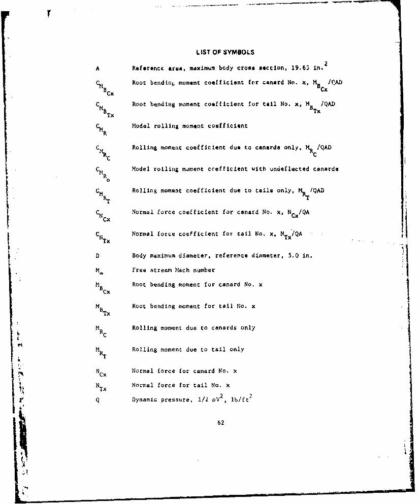
LIST OF SYMBOLS
A Referencc area, mdximum bcdy cross section, 19.63 in.
CM Cx Root bendin6 moment coefficient for canard No. x, MBCX /QAD
C Root bending moment coefficient for tail No. x, MB TX/QADN8 x
CMR Model rolling moment coefficient
C MRolling moment coefficient due to canards only, MR C/QAD
CH Model rolling moment ccefficient with undeflected canards
0
CM Rolling moment coefficient due to tails only, M/QAD'ICNc Normal force coefficient for canard No. x, Ncx/QA
CNTx Normal force coefficient for tail No. x, NTx/QA
D Body maximum diameter, reference diameter, 5.0 in.
M. Free stream Mach number
H Root bending moment for canard No. x
B TX Root bending moment for tail No. x
M RC Rolling moment due to canards only
NRT Rolling moment due to tail only
NCx Normal force for canard No. x
N Normal force for tail No. xTXIi;2 2q Dynamic pressure, 1/2 oV , lb/ft
62

Ii. C .....- Body radiuts St the canard hinge point
RT Body radius at the tail hinge point
V Free stream velocity -
x Canard or tail panel number
a Angle of attack (deg)6Cx DEL Deflection angle for canard No. x (deg)Cx'L x
P Free stream density
6
I
Y*1
II-N!

DISTRI13UTION
Cq.' . Nv M. ofD4111t4a Ducum-ar 'n -antgr AAaqfpathLatr~Alanoti, lruvi~jj j ArTTN Tochnicol 1LibraryI
I" Aro.y Hatoriel Dooj.l.mog~e~An A#..2An Cj, i n.rv
and:" RAtdines, Lo@Vanj DrcoaeAT'T!ncl jr~erch oind UW*vslpbent COir.ah, Oioa41,
AfT:1,t4 on UKL C. 101 HAS.%-Msrshl S pace tl lght CenterWai.h~n IC 23)3ATMh T" hnlc,l Liktrar,I
t'oimAndin8 'Iricor Marshall SpotC@ rlikht Center,LS AMeY PIratifiniy Arw*,ai Alaoa,.a 3';euATMh SMCPAVtJ, Mr, A. L.'.b I L i .r ~J~,)over, how Jet,,, 07801 tSA1N i. Ai,4j,%, gtnOtl
Dire.t.,r ISAr Acadomy. fl' irra® 806tOLb AMYmoNbiliity Reo.af,, on.)hi.~Dievelopaent Lab..ratoy Ah~rO,,t~i illvieitin
ATIhi SAVllL.AS I AwiN. Ttr,.Incs Diilonf,.mrAmo IsgsacI. Cnr.ý TN T#.rvlcgl ln'ttlons
C01104rding Ulticer rlitýItesearch LAb.,ratrtric Na"p't 16001. California V'S63ATTN, SHVEA-RA. Mr. Abraham PFara~. Vf .b Ii InraivILdg*%PO.J Arsenal, Maryland 21010 Inteb Arnraft iional
C"ItdIl itrA1T"; Mr. Fred iiesasmniAif FOr.:. Arwmemnr Leboratoly Cvi.00j~ 94 t~ rilh 2INATINI Mr. I". Butler Coubs Ul )1
Mr. V. Hovaj I Sandia k.orporatio~nDa. F. Flnd,
7o Sandia &as* ivlihian 9J22EILin Air Focla.. floi4. I3214 AT"i IHr. L. CurryArnold E"nginerinj and 04volop-o..t Center A"OX o Nano 11A'mfth; vr. McKay
L.vrary I Purdue UnoiversityArnto'd Air Force Sta-lon. ATTN: Or. 1. Muff.an.Tanrgoeg
PTS rgipu1.i.w CenterAir oruc. tiliht Pvnhatics Laboratory iWiay.ot., Indian. ..go?ATTN' P1*0. Mr. (;oen rip.,a, I -'loat of AlabAmaWri~t-gbt.Parkr., Air Fi'co~ &a,&, upartempt Of Aerotpacq tntineerinsOhio 43.,l
AT"? r Zg
C~loandinx officer Or. J3. 0. DoughtyIAI~IaIXZI Research i-Aforatorieg 011-r.Ity. Aiabrm& 35406ATTN. AIM.hD-*kL. Mr. It, Knioger j Jet Prop3lejun LaboratoryAVIIrdtg. Fwonfr%#_ In round, Maryland 21005 California Institute of Tecnology
COPC-ndni L~f~jr_ - . _ -. ~ - ------ A M:i _ill p. MartinL'S Naval Ordnana~ Laboratories80 O~ada G o,o Daifrnive- ioATIi: Mr. S. Pogstin%& C$tIni lo
M,. Rt T. Ita11 I cnivaroity of Missouri at COolubiaLibrary I ilPAr senL of Mechanical flngiftoerirt
5Whit* OakATN
r.. .Wlirhi3Silver Spring%. MarylandJ 20910 AT" :bria D f.lagouri * hoiN
NASA-langley Retanarch Lontrr L'nlroricy of 11lihoi.ATTN: Mr. Leroy Spo~rean I College Of Engilne~ringMr. C644rit' Jackmann ATTM: Dr. A. L. AddyTechnical Library OrN.I.EraLanglaY field. Virginia 21165 Dr. R. A. Vhira
Comandinil Ufficor ond Director Uran. Il ~ingi LibaryNava) Ship Prnvatr~h nod Development Center Ubn.llnl 10ATTNs: Anr.,!yraelc Laborat-ry 1 J.ohns Hopkins inivereityCardarobk, Maryland 2000) Applied Phystcs LaboratoryNatal weanone Centsr ATTN: Dr. 1. CronvlchATTN: hr. Rt. Masekr K r. Gord. WalkerChina lAb... California 915,5 Mr.i (.o , AWalk*,
SLiver Springs, Maryland Zu910
64

Ho, of fncCup i.e Copies
ni~v.raii y of Motra bass M.cDnnoei-Dvulgil Cstorr.tiun
bopartmeac of Aerospace FASineertin, PU Ibae 1iATTN, In. T. J. Moeller I St. Louis. Mimeouri 63166
Moire Dloe, Indlana 66556Nurthlop Corporation
Soeing Company ilectrsa-tchanical bivisionATTlm Library Unit Chief I ATTNa Mr. I. Clark I
Mr, a. . No ion 1 0 I aSO Let Ortnetlhrops Y20
Mr. H. L. Ctl.a I Anahima, Calif, rnoa 9.601"u bo- 370?Seattle, Waahington f0li26 Etrron lectric Conpany
AMT h Mr. Hobeit oua.. I
Convair, A Divielon of General riOO lorilesantSynamiCs rpora.Lo, St, Lous. Missuwri 73116
ATTWi Di tolen Library I
Powona. California 9j)76 Data Manaogment ServLcesDeportment o10
Niielsen Lr&ineoring and Iesasr:h, Inc. Chroeler Corporation Space Division
ATiTN Dr. Jack 11. Nileeon I ATTN: Mr. N. D. Kemp
150 HOWJd Avenue PO &'e 29200
iuontain View. California V4-00 Ne. OCleans. Loulisian 70189
Hughes AIZmroit C.kpenV Dait Manageinont Services
AM.14, Document. Croop tacnsiosrtomst 3307Library I Chryslir Corporation
Florence Avenue at Teals Street Hointevillie l4ctronis tiviloirn
Culver City, California 90230 ATT: h,. jI. Vaughn102 Wyvn Orite
Lina-tem.o\oua.'vt Aerosapce Curponrtin Huntstville, Alabama 35005
ATM~: Mr. Dick FilioauraPU 5ks 90A DRSMi-tR, Mr. btrickland
Warren. Michigan 45090 -LP, Mr. VuLig-A. Dr. Hcbaniel
LLing-Tn.uo-VooajI;i Aeroapace Corporation D,. KoblrVought Aeronautics Division -ROD 3AI"Mh Z. P. Jesse, LnLt 2-53330 1 -SAD, Mr. Deep ISox 5903 Mr. Burt 15Dailas. ox*las ?522 -PtR (Pe•ord Set) I
(nuforencs Copy) I
Lockheed aipeil end Space Companyi,.uie Umrucmh aod tnglorrrinr G.eyser
ATTN; Mr. J. bonoteiod I
4800 l-'dford Boulevard. ,4WHuntsville. Alebame 35805
Lockhee4 Aircraft CorporationMissile and Space Divislon
AT'IN: Techntclt Information Cent.r I
PU Bos 504
Sunnyvaqle Ceif1orni.
The Martin-Marietta Corporationvirliano DLvisionAITM U. Tipping
L. GilbertOrlando, Floctda 31804
Hcio.onel-Douglaa Company-WestATT.: Library A3-128 I
to -- H- - . -- Dathu California 92646
165
65
S ++::- - -+-i+•4~~~~~. . . .• .. .. . .•... . ... • .5;.--: .;;-. ;: .. ... . . . . . ..:.. .. . .. -- -- • -u -