novel automated software system for arcing simulation · pdf filenovel automated software...
TRANSCRIPT

Novel Automated Software System for Arcing Simulation in Spacecraft On-Board Electronics
Vasily Yu. Kozhevnikov*1, Vadim M. Karaban2, Denis S. Kosov2, Andrey V. Kozyrev1, Alexander V. Batrakov1, Natalia S. Semeniuk1 and Larisa A. Zjulkova1
1Intitute of High Current Electronics, Tomsk, Russian Federation, 2Tomsk State University of Control Systems and Radioelectronics, Tomsk, Russian Federation, *2/3 Akademichesky ave. 634055 Tomsk, Russia, [email protected]
Abstract: In our project, we propose an innovative software solution to the problem of electrical arcing risk prediction in high-voltage on-board electronic equipment intended for long-term self-contained use, e.g. in spacecraft conditions. It completely based on so-called “decomposition” approach proposed earlier. The novel computational algorithm implemented in our software significantly (ten times as compared to full-scale simulation) reduces computation costs. It makes possible to solve large diagnostic problems without high performance computing. Main pre- and post-processing operations are completely automated. As a result we easily locate regions of possible primary arcs (critical regions) and identify corresponding critical ranges of operating parameters. Our working prototype can be easily applied to diagnostics of electronic devices operated under wide range of parameters.
Keywords: Spacecraft Electronics, DC-discharge simulation, Device diagnostics.
1. Introduction
Fault tolerance of the on-board electronicequipment is a critical problem associated with modern satellite telecommunication systems, especially actual for the equipment intended for long-term self-contained use. Thermal and ionizing radiation effects, geomagnetic and electromagnetic fields influences, as well as various types of gas discharges can cause partial or complete failure of the on-board satellite equipment. Modern civil on-board equipment is not sealed or vacuumed. Significant pressure and temperature differences, existence of strong ionizing radiation and intensive chemical reactions at material surfaces frequently cause discharge ignition. Conformably self-sustained discharge contracts to electrical arcing.
Figure 1. Typical damage from primary arc in power supply.
The arcing phenomenon is always associated with a significant energy release, leading to destruction of the on-board equipment components. Due to the cascade effect, secondary arcing is especially damaging because it involves a significant amount of system workspace. Appearance of secondary arcing greatly reduces effectiveness of device duplication technology for single components and entire assemblies of electronic circuits. This problem escalates with the increase of operating voltages from 27 to 100 Volts, followed by even higher voltages. It first arose in 1995 when Boeing Satellite Systems offered the BSS-702 platform with high-voltage bus connected to 100 Volts stabilized power source.
At now, the arcing diagnostics becomes a challenge to electrical engineering due to its complexity. In particular, a significant decrease of the electric breakdown threshold voltage (below Paschen’s law values) was observed in multiple experiments whether metal conductors were partially covered with a dielectric material. This fact gives a fresh look at the problem of fault tolerance, as the destruction of dielectric coating (e.g. lacquer insulation) will significantly increase the probability of arcing.
COMSOL Multiphysics and COMSOL are either registered trademarks or trademarks of COMSOL AB. Microsoft is a registered trademark of Microsoft Corporation in the United States and/or other countries.
Excerpt from the Proceedings of the 2016 COMSOL Conference in Munich
2. Theory
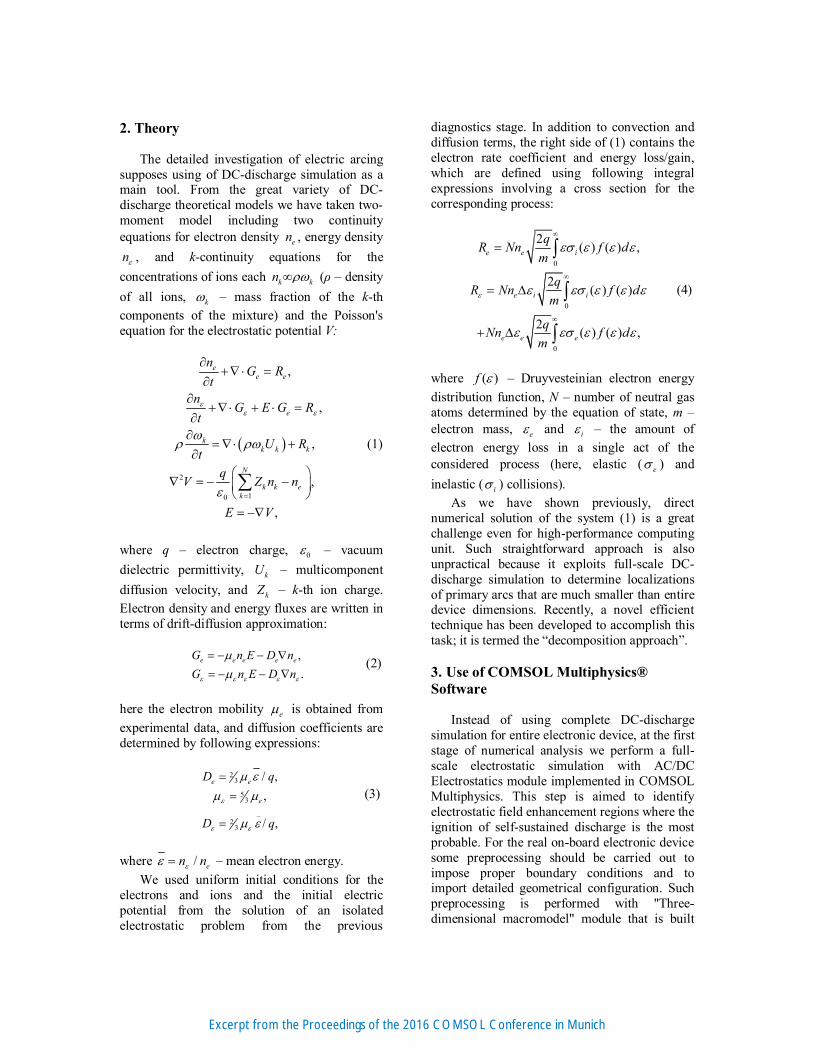
The detailed investigation of electric arcing supposes using of DC-discharge simulation as a main tool. From the great variety of DC-discharge theoretical models we have taken two-moment model including two continuity equations for electron density en , energy density
n , and k-continuity equations for the
concentrations of ions each k kn (ρ – density
of all ions, k – mass fraction of the k-th
components of the mixture) and the Poisson's equation for the electrostatic potential V:
2
10
,
,
,
,
,
ee e
e
kk k k
N
k k ek
nG R
t
nG E G R
t
U Rt
qV Z n n
E V
(1)
where q – electron charge, 0 – vacuum
dielectric permittivity, kU – multicomponent
diffusion velocity, and kZ – k-th ion charge.
Electron density and energy fluxes are written in terms of drift-diffusion approximation:
,
.
e e e e eG n E D n
G n E D n
(2)
here the electron mobility e is obtained from
experimental data, and diffusion coefficients are determined by following expressions:
23
53
_2
3
/ ,
,
/ ,
e e
e
D q
D q
(3)
where / en n – mean electron energy.
We used uniform initial conditions for the electrons and ions and the initial electric potential from the solution of an isolated electrostatic problem from the previous
diagnostics stage. In addition to convection and diffusion terms, the right side of (1) contains the electron rate coefficient and energy loss/gain, which are defined using following integral expressions involving a cross section for the corresponding process:
0
0
0
2( ) ( ) ,
2( ) ( )
2( ) ( ) ,
e e i
e i i
e e e
qR Nn f d
m
qR Nn f d
m
qNn f d
m
(4)
where ( )f – Druyvesteinian electron energy
distribution function, N – number of neutral gas atoms determined by the equation of state, m – electron mass, e and i – the amount of
electron energy loss in a single act of the considered process (here, elastic ( e ) and
inelastic ( i ) collisions).
As we have shown previously, direct numerical solution of the system (1) is a great challenge even for high-performance computing unit. Such straightforward approach is also unpractical because it exploits full-scale DC-discharge simulation to determine localizations of primary arcs that are much smaller than entire device dimensions. Recently, a novel efficient technique has been developed to accomplish this task; it is termed the “decomposition approach”.
3. Use of COMSOL Multiphysics® Software
Instead of using complete DC-discharge simulation for entire electronic device, at the first stage of numerical analysis we perform a full-scale electrostatic simulation with AC/DC Electrostatics module implemented in COMSOL Multiphysics. This step is aimed to identify electrostatic field enhancement regions where the ignition of self-sustained discharge is the most probable. For the real on-board electronic device some preprocessing should be carried out to impose proper boundary conditions and to import detailed geometrical configuration. Such preprocessing is performed with "Three-dimensional macromodel" module that is built
Excerpt from the Proceedings of the 2016 COMSOL Conference in Munich

using COMSOL Application builder. More specifically, the module integrates following features: internal definition and/or import of certain device geometry from CAD software. The PCB layout import is carried out from the electrical computer-aided design system (ECAD) in .PCB ASCII-format. The import of three-dimensional geometry as load-bearing structures (frames) from mechanical computer-aided design (MCAD) is performed in .x_b, .x_t, .dwg, .igs, .step, .stl formats; editing of spatial and surface properties of elements; editing of circuit parameters towards to definition of voltages and internal resistances for power supplies; finite-element meshing adjustment.
After the preprocessing is complete,
stationary electrostatic problem is solved using COMSOL AC/DC Electrostatics module. As an example, below the Figure 2 shows the computed distribution of the electric field norm (a) near the PCB surface for the real onboard satellite power supply (b). As can be seen the electric field enhancement region (highlighted in red color) is located close to the curved part of the PCB track.
Figure 2. Distribution of the electric field norm (a) near the surface of printed circuit board (b) inside grounded metal housing.
In order to solve the full electrostatic problem the most coarse available finite element mesh is used which nevertheless allowing high detailing of simulated device.
The results of current step computations are already allowing make some preliminary conclusions about arcing risk for particular electronic device set. Field enhancement areas are those critical regions (with respect to arcing) that need to be additionally insulated or redesigned to avoid excessive field enhancement.
Further simulation stages follow the preliminary diagnostics, and they aimed to determine ranges of critical parameters. Critical parameters correspond to parameters set for which self-sustained discharge inevitably occurs in critical region. In terms of plasma physics, each critical region is a combination of discharge gaps formed by various elements of electronic device and ambient space.
Due to the fact that all printed circuit boards within the device are typically arranged in parallel (e.g. like in Figure 3), there is an immediate opportunity to apply decomposition approach decoupling it into a very limited set of simple geometric configurations. The decomposition is performed automatically according to results of the previous stage.
Further, the obtained set of two- and three-dimensional discharge gaps configurations (see Figure 4) is subjected to study by means of COMSOL DC-discharge simulation in Plasma module. Here we use “Parametric Sweep” feature in order to go over the most important parameters: pressure, emission current density, initial number of particles. Some of geometrical parameters are also have to be enumerated taking into the account their possible variation in real manufactured device.
Figure 3. Example of satellite-born equipment electronic device.
b)
a)
Excerpt from the Proceedings of the 2016 COMSOL Conference in Munich

Figure 4. Example set of 2D and 2D-axisymmetric discharge gaps configurations extracted from 3D printed circuit board device.
Figure 5. Electron density distribution at self-sustained discharge phase. This 2D model is derived from 3D macro model of real satellite power supply (at Figure 2b)
Special attention is given to COMSOL models extracted using the decomposition approach. In standard DC-discharge interface, we apply the “Cross Section Import” option to implement real experimental cross-section approximation for elastic and ionization collisions for argon. For simplicity reasons, we omit all excited species transport and reactions. An important boundary condition is a secondary electron emission from the cathode surface and dielectrics. It is given with the options “Wall” and “Surface reaction” for all surfaces with parameters of secondary electrons emission coefficients. For the metal surfaces its value usually does not exceed 0.1, while on dielectric surfaces, this value may reach 0.7-0.9 for space conditions. Another crucial physical process to be taken into account is the accumulation of electric charge at dielectric surfaces. Here we use “Surface Charge Accumulation” option in DC Discharge interface. To complete the COMSOL model we set Dirichlet boundary conditions for electrostatic potential distribution at metal surfaces. In current simulation the maximum
anode voltage is equal to 100 Volts that is the below breakdown voltage in argon following Paschen’s law. Mesh choice based on internal COMSOL setting “Physics-controlled mesh” with “Normal” or “Coarse” element size.
The “Processing core” module also built with COMSOL Application builder assigns all necessary boundary and initial (uniform) conditions as well as basic solver options automatically. It also includes data output in ASCII and graphics formats during DC discharge simulation.
The main outcome of the simulation is a multidimensional critical diagram obtained by using “Parametric Sweep” feature. Typical critical diagram (in Figure 6) shows safe and unsafe parameters areas with respect to possible self-sustained discharge ignition. Arc discharge ignition at critical diagram corresponds to area where the steady-state current density is sufficiently high. In order to estimate threshold current density the DC-discharge simulation can be performed with “reference” anode voltage that has to be taken above breakdown value.
The resulting set of critical diagrams gives the comprehensive information about arcing vulnerabilities of the entire device without resorting to full-scale three-dimensional discharge simulation. Entire computational methodology is implemented in our pilot software allowing to reduce diagnostics time of onboard equipment manifold (ten times as compared to full-scale simulation).
Figure 6. Pressure vs. Emission from dielectric critical diagram example. Color bar (at left) depicts the level of discharge current density.
Excerpt from the Proceedings of the 2016 COMSOL Conference in Munich

4. Conclusions
The previously proposed computational approach has been successfully applied to the investigation of arcing risk in large-scale satellite onboard power devices. We have been implemented our innovative approach in pilot software system ready-built with COMSOL Multiphysics. COMSOL Application builder was used along with COMSOL AC/DC Electrostatics and Plasma modules in order to construct complete simulation cycle. The developed software enables to combine possible arc positioning with the further investigation of certain regimes of discharge ignition. Some simulation results are exhibited good agreement with laboratory measurements.
At present the Ministry of Education and Science of Russian Federation accepts the proposed software system as the main simulation tool of the project “Development of methods for complex diagnostics of onboard equipment of spacecraft on resistance to arcing” (Project ID is RFMEFI60714X0008).
5. References 1. R. Leach, Spacecraft system failures and anomalies attributed to the natural space environment, Space Programs and Technologies Conference, (1995) 2. B. M. Smirnov, Theory of Gas Discharge Plasma, Springer Series on Atomic, Optical, and Plasma Physics (2015) 3. A. V. Batrakov, K. V. Karlik, V. S. Kim, S. G. Kochura, V. A. Lavrinovich, S. A. Popov and S. B. Suntsov, Statement of the problem and experimental study of the secondary arcing in the conditions of orbital space, 2014 International Symposium on Discharges and Electrical Insulation in Vacuum (ISDEIV), pp.725-727 (2014) 4. A. V. Kozyrev, V. Y. Kozhevnikov, N.S. Semeniuk, and L.A. Zyulkova, Theoretical Simulation of a Gas Breakdown Initiated by External Plasma Source in the Gap With Combined Metal-Dielectric Electrodes, IEEE Transactions on Plasma Science, Vol. 43, Issue 8, pp. 2294–2298 (2015) 5. V. Y. Kozhevnikov, A. V. Kozyrev, A. V. Batrakov, N. S. Semeniuk, V. M. Karaban, D. S. Kosov, Design and
Diagnostics of Arc-resistant Electronics for Satellite Telecommunication Systems, 18th Mediterranean Electrotechnical Conference (MELECON) (2016) 6. V. M. Karaban, D. S. Kosov, ASC Permanent Arc, certificate of state registration of computer programs №2016614035
6. Acknowledgements
Authors express their sincere gratitude to all colleagues and friends who voted for their competition project “Automated Software System for the Simulation of Arcing in Spacecraft On-Board Power Electronics Equipment”.
Excerpt from the Proceedings of the 2016 COMSOL Conference in Munich