novadrier membrane dryer for plastics
TRANSCRIPT
U.S. Patent No. US 6,584,701 B1
Document: ND IM 3 JAN 2017
NovaDrier™ MEMBRANE DRYER for Plastics
MODELS: ND-7, ND-25, ND-50, ND-75,
ND-100, ND-150, ND-200
©NOVATEC, Inc. 2017 All Rights Reserved
NOTE: See important information about air supply on next page.

Instruction Manual ND IM 3 JAN 2017
Instruction Manual IM ND 3 JAN 2017 Page 2
NOTES:
Please record the following information, which is specific to this piece of equipment, in the space provided. Our Parts/Service Department will need these numbers to properly respond to any of your requests.
Instruction Manual: ND IM 3 JAN 2017 Model #:___________________________ Serial #____________________________
DISCLAIMER: NOVATEC, Inc. shall not be liable for errors contained in this Instruction Manual nor for misinterpretation of information contained herein. NOVATEC shall not, in any event, be held liable for any special, indirect or consequential damages in connection with performance or use of this information.

Instruction Manual ND IM 3 JAN 2017
Instruction Manual IM ND 3 JAN 2017 Page 3
Table of Contents 1-UNPACKING AND INSPECTION ..................................................................................................... 4
1.1 Unpacking ................................................................................................................................... 4
1.2 General Inspection & Mounting ................................................................................................ 5
1.3 Clamp Ring Inspection .............................................................................................................. 6 2 SPECIFICATIONS ............................................................................................................................. 7
2.1 NovaDrier STANDARD COMPONENT Set Points .................................................................... 7
3 INSTALLATION ................................................................................................................................. 8 3.1 Mounting The Dryer ................................................................................................................... 8
3.2 Connecting Power...................................................................................................................... 8 3.3 Compressed Air ......................................................................................................................... 9
3.3.1 Compressed Air Requirements .......................................................................................... 9
3.3.2 Connecting Compressed Air ............................................................................................. 10 3.3.3 Condensate Drains ............................................................................................................ 10
4 DESCRIPTION OF OPERATION .................................................................................................... 11
5 INITIAL START-UP & OPERATION ............................................................................................... 12 5.1 Turning The Dryer On .............................................................................................................. 12
5.4 Other Parameters ..................................................................................................................... 14
6 USING THE 7 DAY TIMER OPTION: .............................................................................................. 15 7 SETTING ENERGY SAVER OPTION ON ND-100 AND LARGER SIZES...................................... 16
8 UPDATING FIRMWARE .................................................................................................................. 17
9 TROUBLESHOOTING GUIDE ........................................................................................................ 18 9.1 Dryer Fault Lights .................................................................................................................... 18
9.2 Power Failure ........................................................................................................................... 18
9.3 Troubleshooting Chart ............................................................................................................ 19 10 MAINTENANCE AND INSPECTION SCHEDULE ........................................................................ 20
10.1 Vendor Instructions ............................................................................................................... 22
10.1.1Compressed Air Inlet Filters ............................................................................................ 22 10.1.2 Round Re-Circulation Air Filter....................................................................................... 23
10.1.3 Heater Housing Thermostat ............................................................................................ 23
10.1.4 Spare Parts Notes ............................................................................................................ 23 11 WARRANTY – NOVATEC, INC. - Effective Date 21 SEPT 2016 ................................................ 24
Instruction Manual ND IM 3 JAN 2017
Instruction Manual IM ND 3 JAN 2017 Page 4
1- UNPACKING AND INSPECTION
Congratulations, you have purchased the finest Dryer on the market from the finest dryer manufacturer. It has a (2) year warranty (as long as you replace the filter elements regularly and exercise good maintenance – see the warranty information in section 8). This manual will provide you with proper procedures to insure that you will be completely satisfied with your purchase. Please review this manual carefully.
1.1 Unpacking
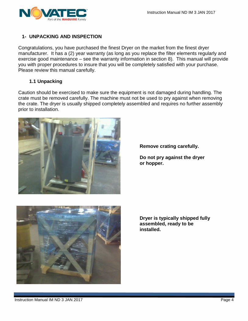
Caution should be exercised to make sure the equipment is not damaged during handling. The crate must be removed carefully. The machine must not be used to pry against when removing the crate. The dryer is usually shipped completely assembled and requires no further assembly prior to installation.
Remove crating carefully. Do not pry against the dryer or hopper.
Dryer is typically shipped fully assembled, ready to be installed.

Instruction Manual ND IM 3 JAN 2017
Instruction Manual IM ND 3 JAN 2017 Page 5
1.2 General Inspection & Mounting
When the unit is unpacked, make a visual inspection looking for missing parts or damage, which may have occurred during shipment. Some parts, such as hoses, and hose clamps may be packed inside the hopper as well as the instruction manual. It is important that all electrical and piping connections should be checked for tightness because vibration during transit may cause them to loosen. Inside of the hopper door, the (2) perforated air diffuser tubes (upper & lower) should be thoroughly cleaned to remove any dust, moisture or oil that may have accumulated during shipment. The diffuser tubes must be reinstalled so they are properly aligned and secure. The upper diffuser tube must be installed at the end of the vertical tube in the center of the hopper (it is a friction fit) and should stick out from the end of this tube as follows:
NovaDrier Upper Diffuser Tube
NovaDrier Lower Diffuser Tube
Optional Short Run Diffuser Tube for use when hopper is less than 100% full. NOTE: NovaDriers should always be run with a 100% full hopper- never below 75% full.
Instruction Manual ND IM 3 JAN 2017
Instruction Manual IM ND 3 JAN 2017 Page 6
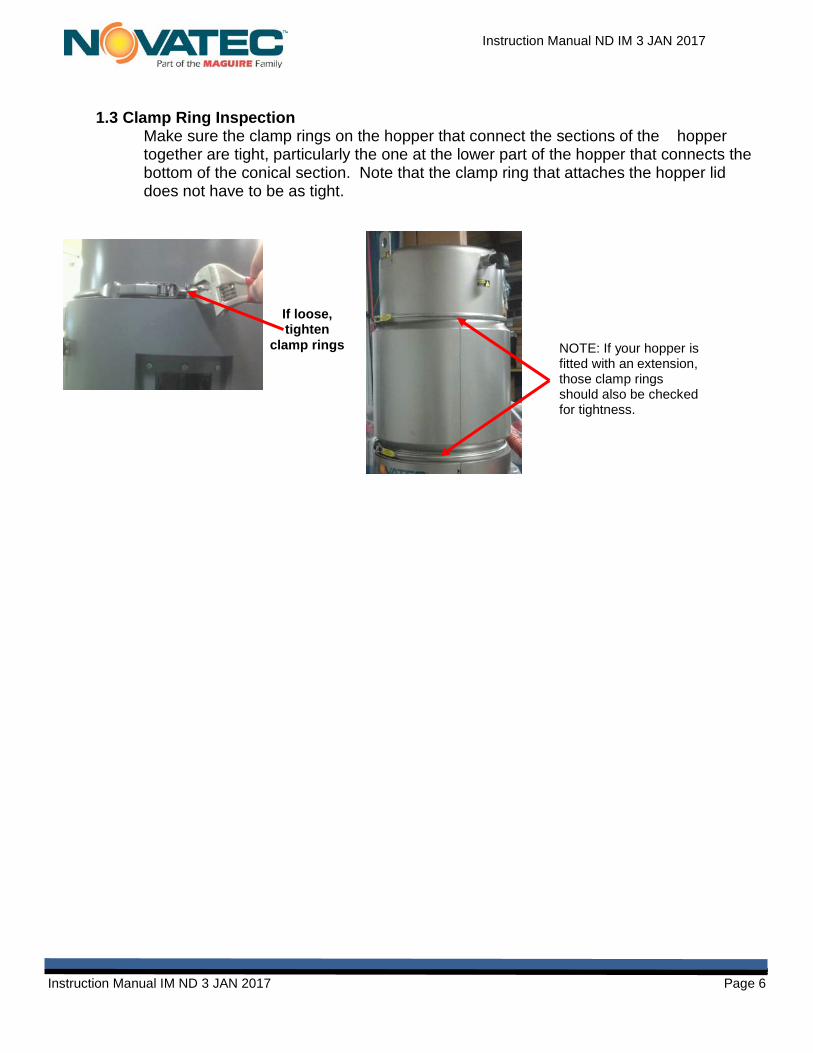
1.3 Clamp Ring Inspection Make sure the clamp rings on the hopper that connect the sections of the hopper together are tight, particularly the one at the lower part of the hopper that connects the bottom of the conical section. Note that the clamp ring that attaches the hopper lid does not have to be as tight.
If loose, tighten
clamp rings NOTE: If your hopper is fitted with an extension, those clamp rings should also be checked for tightness.

Instruction Manual ND IM 3 JAN 2017
Instruction Manual IM ND 3 JAN 2017 Page 7
ALL MODELS
2 SPECIFICATIONS
**Note: If set point is exceeded by 5°F (3°C) the heater will shut down for 1 minute to allow it to come back to set point. If it does not, the dryer will alarm and shut down.
2.1 NovaDrier STANDARD COMPONENT Set Points
Air Amplifier setting: See sticker inside control box LOWER air pressure regulator setting (R1) - located inside the upper part of the control box:
See sticker inside control box
UPPER air pressure regulator setting (R2) - located inside the lower part of the control box:
See sticker inside control box
Low air pressure switch: 70 PSIG (4.7 BagG) Over-temperature shut-down set point from both the temperature controllers (see **note above):
5°F (3°C) higher than the control set point after one minute
Angle needle valve that controls flow to Hygro Dew Point Sensor option (if supplied): (2) turns open from full closed
Heater Thermostats - legend “TSH” (if supplied): 375°F (191°F)
Required Compressed Air Pressure - PSIG 85-125 psig (5.9 -8.7 Barg)Max. Temperature
°F/ºC 100°F / 38°C Max Inlet Dew Point
°F/ºC 100°F / 38°C Process Air Outlet Temp. °F/ºC (max) 350ºF / 163°C
Process Air Dew Point (max) -40ºF / -40ºC

Instruction Manual ND IM 3 JAN 2017
Instruction Manual IM ND 3 JAN 2017 Page 8
3 INSTALLATION
3.1 Mounting The Dryer Mount the NovaDrier to the processing machine (if machine mounted). Use the control panel support bracket supplied on the bottom of the control box, as the control box must be supported properly.
CAUTION: FOLLOW ALL NATIONAL AND LOCAL ELECTRICAL AND MECHANICAL CODES, AS REQUIRED. ONLY QUALIFIED AND TRAINED PERSONEL SHOULD INSTALL AND OPERATE THIS EQUIPMENT
3.2 Connecting Power Refer to the specifications in Section 2 and the mechanical and electrical drawings provided.
Connect the required electrical power to the unit through a main line disconnect (field supplied) as indicated on the NOVATEC nameplate, which is located on the side of the control box. Because the controllers and various sensors are sensitive to “Industrial Noise” the system must be properly connected to true earth ground. This is the only power connection necessary as the system is completely pre-wired.
Main power connection inside control panel
NovaDrier machine mounting.
Control panel support bracket. (Must be installed)

Instruction Manual ND IM 3 JAN 2017
Instruction Manual IM ND 3 JAN 2017 Page 9
3.3 Compressed Air
3.3.1 Compressed Air Requirements
IMPORTANT NOTE: The introduction of OZONE to the flow of compressed air will damage the membrane and void the warranty.
OZONE in the atmosphere near the air compressor intake can also damage the NovaDrier membrane.
To avoid membrane damage from atmospheric ozone please order and install the Catalyst Modules listed above.

Instruction Manual ND IM 3 JAN 2017
Instruction Manual IM ND 3 JAN 2017 Page 10
3.3.2 Connecting Compressed Air Connect a clean, ozone-free, vapor-free and liquid water-free compressed air line to the
compressed air inlet ball valve located on the left side of the control panel. See the minimum compressed air inlet line size requirement below. The
pressure of the compressed air to the system should be at least 85 psig but not more than 125 psi (note that the system will run more efficiently at higher air pressures). The inlet compressed air temperature should be less that 100°F. Note that the (2) coalescing inlet compressed air filters on the NovaDrier each have an internal condensate trap that is designed to remove small amounts of water droplets
from un-dried incoming compressed air but they are not designed to remove liquid water. Make sure that hazardous vapors, like solvents or ozone, are not being introduced into the compressed air system that is feeding the NovaDrier.
3.3.3 Condensate Drains Connect the automatic compressed air condensate drains at the bottom of the
(2) compressed air filters on the side of the cabinet, so the condensate iscaptured and disposed of properly. If the drains are not piped away, oily watermay spray down periodically from the automatic drains. Use a 1/8” npt malefitting to connect into each drain.
MODEL ND-7 ND-25 ND-50 ND-75 ND-100 ND-150 ND-200
Minimum compressed air
line size 3/8” hose or 10 mm
3/8” hose or 10 mm
3/8” hose or 10mm
3/8” hose or 10mm
1/2" hose or 12 mm
3/4" hose or 20 mm
3/4” hose or 20mm
Connect air LOWER of 85-125 psig here.
Condensate drains: Collect discharge or attach drain lines.
See chart below for proper line
compressed air line size for your dryer model, or
the sticker on dryer cabinet.
DO NOT USE REDUCERS THAT WILL
RESTRICT AIR
IMPORTANT

Instruction Manual ND IM 3 JAN 2017
Instruction Manual IM ND 3 JAN 2017 Page 11
4 DESCRIPTION OF OPERATION
• Compressed air is filtered by two coalescing filters in series, to remove all aerosols aswell as any particles, all down to 0.01 micron.
• Inside the control box the compressed air flow splits. The bulk of the airstream isexpanded to atmospheric pressure through a pressure regulator (to lower the dew point),heated and injected into the middle of the hopper. An Air Amplifier, driven by theexpansion of the compressed air, is used to re-circulate much of the air in the upper partof the hopper.
• This insures that heat is transferred into the material quickly, evenly and at the correctvelocity, to insure good drying. The inlet air temperature to the hopper is controlled by athermocouple and a solid state temperature controller (located in the right side of thecontrol box and it is the top controller & labeled “UPPER HEAT”).
• The rest of the compressed air goes through a special membrane, located inside thecontrol box. This membrane filters out the water vapor, which is continuously exhaustedthrough vents in the side.
• The dry air is then expanded to atmospheric pressure through a pressure regulator,heated and injected into the bottom of the hopper to dry the material in the lower part ofthe hopper. The dry air temperature to the lower part of the hopper is controlled by athermocouple and a solid state temperature controller (located in the right side of thecontrol box and it is the one on the bottom labeled “LOWER”). After drying the material,the moisture laden air is vented through the relief valve at the top of the hopper.
5 Air Flow Diagram of the patented NovaDrier™
Patent # 6,584,701 B1

Instruction Manual ND IM 3 JAN 2017
Instruction Manual IM ND 3 JAN 2017 Page 12
5 INITIAL START-UP & OPERATION
WARNING: 1) Never turn off the compressed air flow to the system while power is on, as compressed
air must always be flowing for proper operation of the heaters and to avoid product and system damage from overheating and poor temperature control.
2) The (2) insulated heaters and the piping from the heaters inside the control box are hot. When operating the system with the door of the control box off, be careful to avoid touching these hot surfaces.
3) If the NovaDrier is mounted on a floor stand with casters, be careful moving it, to avoid tipping, as damage and injury may result. Material loaders and other equipment located on top of the drying hopper will increase the need for care when moving this equipment.
4) The drying hopper and the red silicone hoses may be hot. 5) Only qualified and properly trained personal should operate this equipment!
Refer to the drawing and the information in this Technical Manual. Contact NOV ATEC if there are any questions about how to operate or maintain this equipment!
Before starting, the compressed air inlet valve (located on the side of the dryer) must be fully open.
Fill the hopper with material, being careful not to overfill it. The hopper should never be less full than the Minimum Level arrow next to the sight glass. When ready to start the system, fully open the compressed air inlet valve (located on the side of the dryer cabinet) and assure that a minimum of 85 psi shows on the dryer’s air pressure gauge. Compressed air should be flowing through the system. Turn on control and immediately set both temperature controls to the proper drying temperature (see “Changing the Drying Temperature”, below).
5.1 Turning The Dryer On After making sure that compressed air is flowing to the dryer (pressure gauge should show 85-125 psi), and making sure that the drying hopper is filled to above the minimum level shown next to the sight glass, turn the dryer “ON” using this switch.
Control will display the factory default of 160F°.
Valve in CLOSED
(horizontal) position.
Valve in OPEN
(vertical) position.
Air
To Dryer
Air

Instruction Manual ND IM 3 JAN 2017
Instruction Manual IM ND 3 JAN 2017 Page 13
5.2 Choosing F° or C°
On the display under UPPER HEAT – (NOTE: initial temps shown are the set points entered during testing.)
unt
Selecting F° or C° for Dew Point
1- Find the board behind the dew point display.2- Press & HOLD one of the two white buttons.3- The display will change to the new selection.4- Release the button and the dew point readout
will be in the new selection.
1- Press the upper left and lower rightbuttons at the same time.
2- The display will show Unt (Units).Press the upper left button “SELECT”
3- Press or button to select C for centigrade.
4- Press “ENTER” to save changeand exit.
Instruction Manual ND IM 3 JAN 2017
Instruction Manual IM ND 3 JAN 2017 Page 14
5.3 Changing The Drying Temperature
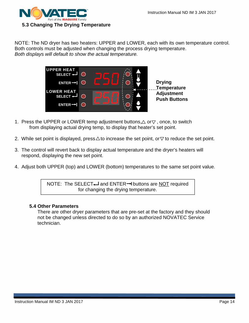
NOTE: The ND dryer has two heaters: UPPER and LOWER, each with its own temperature control. Both controls must be adjusted when changing the process drying temperature. Both displays will default to show the actual temperature.
1. Press the UPPER or LOWER temp adjustment buttons, or , once, to switchfrom displaying actual drying temp, to display that heater’s set point.
2. While set point is displayed, press to increase the set point, or to reduce the set point.
3. The control will revert back to display actual temperature and the dryer’s heaters willrespond, displaying the new set point.
4. Adjust both UPPER (top) and LOWER (bottom) temperatures to the same set point value.
5.4 Other Parameters There are other dryer parameters that are pre-set at the factory and they should not be changed unless directed to do so by an authorized NOVATEC Service technician.
NOTE: The SELECT and ENTER buttons are NOT required for changing the drying temperature.
Drying Temperature Adjustment Push Buttons
UPPER HEAT SELECT
ENTER
LOWER HEAT SELECT
ENTER
Instruction Manual ND IM 3 JAN 2017
Instruction Manual IM ND 3 JAN 2017 Page 15
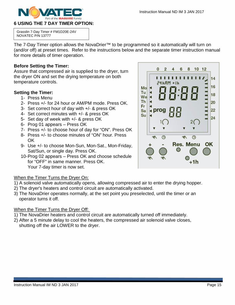
6 USING THE 7 DAY TIMER OPTION:
The 7-Day Timer option allows the NovaDrier™ to be programmed so it automatically will turn on (and/or off) at preset times. Refer to the instructions below and the separate timer instruction manual for more details of timer operation.
Before Setting the Timer: Assure that compressed air is supplied to the dryer, turn the dryer ON and set the drying temperature on both temperature controls.
Setting the Timer: 1- Press Menu2- Press +/- for 24 hour or AM/PM mode. Press OK.3- Set correct hour of day with +/- & press OK4- Set correct minutes with +/- & press OK5- Set day of week with +/- & press OK6- Prog 01 appears – Press OK7- Press +/- to choose hour of day for “ON”. Press OK8- Press +/- to choose minutes of “ON” hour. Press
OK9- Use +/- to choose Mon-Sun, Mon-Sat., Mon-Friday,
Sat/Sun, or single day. Press OK.10- Prog 02 appears – Press OK and choose schedule
for “OFF” in same manner. Press OK.Your 7-day timer is now set.
When the Timer Turns the Dryer On: 1) A solenoid valve automatically opens, allowing compressed air to enter the drying hopper.2) The dryer's heaters and control circuit are automatically activated.3) The NovaDrier operates normally, at the set point you preselected, until the timer or an
operator turns it off.
When the Timer Turns the Dryer Off: 1) The NovaDrier heaters and control circuit are automatically turned off immediately.2) After a 5 minute delay to cool the heaters, the compressed air solenoid valve closes,
shutting off the air LOWER to the dryer.
Grasslin 7-Day Timer # FM1D20E-24V NOVATEC P/N 13777

Instruction Manual ND IM 3 JAN 2017
Instruction Manual IM ND 3 JAN 2017 Page 16
7 SETTING ENERGY SAVER OPTION ON ND-100 AND LARGER SIZES
1. Press and Hold the UPPER “SELECT” and “↓” down arrow buttons for five seconds when “Unt” appears on the UPPER display.
2. Press “↓” three times to make ES appear on the UPPER display. 3. Press “SELECT” and “OFF” will appear on the UPPER display 4. Press “↑” to select the desired Return Air
Temperature at which the Energy Saver function should engage. Press “ENTER” twice to exit the menu.
5. If the Return Air Temperature is greater than or equal to the Energy Saver functions set point “EnG” will appear and the power to the UPPER Heater will turn off. Note: Air will continue flowing to the UPPER heater for five minutes after the Energy Saver function engages to ensure proper cooling of the heaters elements.
6. When Return Air Temperature falls below the Energy Saver functions set point the UPPER Heater will turn back on and if the air LOWER to the heater was “OFF” the air LOWER will then re-open. Note: If the Energy Saver function cycles faster than every five minutes compressed air will never turn off. To improve energy savings lower the Energy Saver functions set point to lengthen the amount of time the UPPER Heater remains “OFF”.
To turn off the Energy Saver Option:
1. Press and Hold the UPPER “SELECT” and “↓” down arrow buttons for five seconds when “Unt” appears on the UPPER display.
2. Press “↓” three times to make ES appear on the UPPER display.
3. Press “SELECT” and the Energy Saver function set point will appear on the UPPER display. 4. Press “↓” until the UPPER display reads “OFF” 5. Press “ENTER” twice to exit the menu.
To Monitor the Return Air Temperature
1. Press and Hold the UPPER “SELECT” and the LOWER “SELECT” buttons for five seconds. 2. After five seconds the Return Air Temperature will be displayed on the UPPER display. The
Return Air Temperature will remain displayed as long as the two “SELECT” buttons are depressed.
3. Release the “SELECT” buttons and the UPPER display will return to the UPPER Heater Temperature.

Instruction Manual ND IM 3 JAN 2017
Instruction Manual IM ND 3 JAN 2017 Page 17
8 UPDATING FIRMWARE
When the NovaDrier is powered on, the Temperature Control Dual Display will show the current firmware version across both displays. When required or advised, firmware updates are loaded into the NovaDrier via a SD flash memory card.
The SD flash memory card slot is located within the NovaDrier’s electrical cabinet. Firmware updates can be supplied via shipment of a pre-loaded SD flash memory flash card or may be downloaded or sent via email and loaded onto your own SD flash memory card.
Firmware Updates apply when the NovaDrier is turned on. After the firmware is updated, the firmware file is deleted from the SD card. This is to prevent repeated update attempts of the firmware in the event that the flash card is left in the SD slot indefinitely. If more than one NovaDrier is to be updated, request additional pre-loaded SD cards from NOVATEC, or instructions on copying the file onto your computer prior to updating, so the card can be reloaded for updating other dryers.
Procedure: 1. Disconnect power to the NovaDrier prior to opening the electrical cabinet. The cabinet door
opens by rotating the two ¼-turn latches counter-clockwise. Locate the elevated printedcircuit board in the lower left corner of the cabinet and the SD card slot on its base.
2. Insert the SD update card into the slot until it clicks. Note that some dryers have “large”slots (about an inch wide) and some have “small” slots (about ½” wide).Small slots take the SD card directly. Large slots require the use of anSD card adaptor.
3. Close the electrical box door and close the ¼ - turn latches. Reconnectpower.
4. To update the firmware, turn on the machine. On power up, the UPPERand LOWER displays will show “UPT” and an incremental counter from000 to 100. It will then display the new firmware version.
5. Once the updated version disappears and temperature is once again displayed on thereadouts, the update is complete. Shut the dryer off once again and disconnect power.Open the cabinet and remove the SD card.
6. Default settings must be reloaded following a firmware update. At the dryer’s dual controlreadouts, use the upper “UPPER” display and press the upper left and lower right buttonssimultaneously to enter Set-up mode.
7. Use the up and down buttons of the UPPER readout to navigate to the setting “LdF” (LoadFactory defaults), then hold the Select (upper left) button down for 2 seconds.
8. When the Select button is released “dne” (done) will be displayed on the top readout,indicating the factory default settings are done being restored.
9. NovaDrier’s equipped with the Energy Saver feature must be have this feature re-activatedand the Energy Saver temperature set, to complete the firmware update process.
10. At the dryers’ dual control readouts, use the upper “UPPER” display and press the upperleft and lower right buttons simultaneously to once again, enter Set-up mode.
11. Use the up and down buttons to navigate to the setting “ES” (Energy Saver).12. Press the Select (upper left) button and view ”Off” setting on the readout. The desired
energy saver temperature may now be set with the up and down arrows.13. Lock in your setting by pressing the lower left Enter button and the dryer is now ready to
operate normally with the updated firmware.
1

Instruction Manual ND IM 3 JAN 2017
Instruction Manual IM ND 3 JAN 2017 Page 18
9 TROUBLESHOOTING GUIDE
Note that most drying problems are the result of dirty filter(s), too high a material flow or air leaks. It is seldom that components fail.
9.1 Dryer Fault Lights
OVER TEMP Light is On: This is factory set to shut down both heaters when the air temperature from either heater rises about 15°F higher than the set point.
1.Usually the result of incorrect deviation or alarm set points in temperaturecontroller(s). Refer to Section 4, “Parameters-Full Explanation” in this manual to adjustsettings for yourParticular drying application.2.Thermocouple failure(s). Repair or replace the thermocouple(s).
Once the reason for the over temperature alarm is corrected, and the heaters have cooled down, you can restart the heaters by turning the control switch off and then on to reset the control.
LOW AIR PRESSURE Light is On: An internal pressure switch detects insufficient compressed airflow and heaters are automatically turned off. 1.Be sure air LOWER valve is fully on (handle is vertical) and ample air is supplied (85 psi +)as read on the pressure gauge on the side of the cabinet.2.Drain water and clean drainage tubes and/or base of filters, or replace both filters.
NOTE: Visible liquid in the sight glasses, located on the side of the compressed air filter modules indicates a blockage in the drainage system at the base of the filter, or a saturated filter. To assure good drainage flow, inspect and clean the base fitting of the filter and the drainage line (if installed) to assure that there are no blockages that might prevent the automatic liquid evacuation from the filter. If this does not remedy the collection of visible liquid, the filters should be replaced.
WARNING: BEFORE OPENING THE DOOR OF THE CONTROL BOX, DISCONNECT ALL POWER TO THE UNIT AND TURN OFF THE COMPRESSED AIR TO THE NOVADRIER! NOTE THAT THE SMALL “ON/OFF” ELECTRICAL SWITCH, LOCATED ON THE SIDE OF THE CABINET, DISCONNECTS ONLY THE CONTROL POWER AND DOES NOT SHUT-OFF THE MAIN POWER INTO THE UNIT.
Sight Glasses
Drains 9.2 Power Failure
A power failure will de-energize the controls and the heaters but compressed air will continue to flow through the system and be dried through the filters and membrane. When the power is restored, the system will automatically come back on and resume operation.

Instruction Manual ND IM 3 JAN 2017
Instruction Manual IM ND 3 JAN 2017 Page 19
9.3 Troubleshooting Chart PROBLEM TROUBLESHOOTING CODE
Power won’t come on (“POWER” light off on panel) A, B, C No or low inlet compressed air pressure F, G, H, I Inadequate or no process heat D, E, F, G, H, I, M, S Material not being dried properly D, E, F, G, H, I, J, K, M, N, O, P, Q, R, S High air dew point F, G, H, I, J, L,N
I Inlet compressed air LOWER pressure is
less than 85 psi, as read on the pressure
gauge supplied on the left side of the unit.
Low inlet compressed air LOWER pressure. Red
light “low compressed air pressure” may be on.
• Air inlet valve fully open?
• Check airline to NovaDrier for obstructions
or restrictions.
• Is airline the correctly size per specification
sheet on p3?
• Are there airline “quick connects” with
restrictive internals & check valve that is
reducing the air pressure?
• Check plant air system.
J Inlet compressed air LOWER temperature
is more than 100°F
High inlet compressed air LOWER temperature. Check plant air system & correct so the inlet
temperature is below 100°F.
K Relief valve (on top of hopper) Clogged with material or dust. Clean dust out. On the ½” & ¾” npt brass
valves on models
N-7, N-25 & N-50: unscrew valve body & clean
valve disk.
L Dew Point Sensor (optional feature, if
supplied)
Not operating:
Hi or Erratic Dew Point:
• Check cable & wiring for breaks or tightness.
• Replace sensor- change yearly
• Check for air leaks into sensor or in tubing to
sensor.
CODE CHECK CONDITIONS SOLUTIONS A Power LOWER No voltage or incorrect voltage Check field installed disconnect or incoming
voltage. B Transformer (if supplied) No voltage on primary:
No voltage on secondary: • See code “A”• Check fuse – if ok & power to primary,
replace transformerC Light bulb Burnt out Replace D Heater amperage Voltage correct but amps incorrect (check both
heaters inside box) Replace heater element as required
E Re-circulation air filter (located at the top of the box, unscrew the top wing nut to replace)
Dirty filter restricting the re-circulation air flow Replace filter element (replace about very 6 month min, as required)
F Two Compressed air inlet filters (on left side of box & red in color).
One or both of the air pressure drop indicators on top of the filters have changed from green to red, indicating a clogged filter element.
Replace both filter elements – (Both filters must be replaced yearly to maintain warranty!).
G Two Compressed air inlet filters (on left side of box & red in color).
Condensate from one or both filters not draining from the automatic traps in the bottom of each filter. This will cause a high dew point from the Dryer & a high air pressure drop across the filters. Water shows in the level gauge on the side of the filter(s).
• Check air filter drain tubing (if installed) for restrictions.
• Make sure the filter is vertical.• Clean or replace the automatic drain, as
required.H Leaks in system Air leaking out of system causing poor performance. • Check piping & gasket for leaks; repair or
replace as required. • Check clamp ring(s) & door clamps on
hopper to make sure they’re tight, gasketsare okay & sealing properly.
• Gate valve on material drain valve at the bottom of hopper on the side is fully closed & (2) setscrews are tight.
• Check air tubing inside of control box tomake sure their connected properly. Checkall hoses to make sure hose clamps are tight & hoses are not damaged.
• Wing nut on top of round filter housing (F3) on top of control box is tight.

Instruction Manual ND IM 3 JAN 2017
Instruction Manual IM ND 3 JAN 2017 Page 20
CODE CHECK CONDITIONS SOLUTIONS
M (2) Temperature controllers for
heaters
Adjustment incorrect:
Not controlling properly:
Heater over temperature shuts down system & red
light “Heater Overtemp” is on.
• Re-check process air set points per section 4
• Check for loose wiring.
• Check thermocouple for proper operation,
tightness & correct installation (replace if
required).
• Auto Tune controller(s) per instructions at end of
section.
• See over temperature settings in section 1.
Readjust deviation alarm per instructions in sect. 9
(if req.) or thermostats (if supplied).
• Low compressed airflow (see sections F, G, H, I).
• To reset heaters, when the heaters havecooled, turn power on & off using the on/off switch.
N Lower & Upper air pressure
regulators inside of box.
Regulators out of adjustment resulting in incorrect
air flow to hopper. Low airflow causes inadequate
drying & high airflow may cause the heaters to
deliver air at too low a temperature.
Refer to the set points on the label inside the box.
O LOWER orifice Orifice plugged with material. This is a hex shaped
brass fitting screwed into air inlet of LOWER heater
(H1).
Remove the orifice & clean out the particles (if
required).
P Upper & lower screen in hopper. Screens are clogged with material.
Screens are positioned incorrectly and not straight.
Remove & clean (see General Inspection section on p4 for the proper position of this screen).
See General Inspection section on page 4 for the proper position of this screen.
Q Material level in hopper. Low material level in hopper reducing the drying
efficiency.
Make sure the material level in the hopper is always
at least 75% full and preferably 100% full.
R Initial moisture content in the plastic
material being dried.
Higher than normal moisture content of the
material being loaded into the hopper is
reducing the Dryer efficiency.
The material being dried should be sealed until it is
ready to be dried, to keep it from picking up additional
moisture from the atmosphere.
S Heater housing Thermostat(s) – if
supplied
Adjustment incorrect causing the heaters to turn
off & lock out.
Re-check the set point (see the set point on page 4).
Re-adjust the thermostat if required.

Instruction Manual ND IM 3 JAN 2017
Instruction Manual IM ND 3 JAN 2017 Page 21
10 MAINTENANCE AND INSPECTION SCHEDULE
It is recommended that maintenance and inspection is done on a scheduled basis. Maintenance requirements will naturally vary widely for each installation and with specific operating conditions. It is suggested that a complete inspection be performed with necessary maintenance at the end of the first month, the first three months, and the first six months. These inspections can determine how often future maintenance will be necessary. The system has been designed with no moving parts to keep maintenance to a minimum.
The special membrane, located inside the control box, is designed to last indefinitely under normal operating conditions and with proper care. To properly protect the membrane, the inlet compressed air filter elements (the two compressed air filters on the side of the unit) must be replaced every 12 months. These replacements must be documented to maintain the 2-year warranty.
Also, liquid water and oil from the compressed air LOWER system must be prevented from entering the dryer as this will permanently damage the dryer media and it may have to be replaced.
Every Month:
A. Check system for air leaks or flow obstructions and correct as required.
B. Inspect the re-circulated air filter (located with the filter housing on the top of the control cabinet).Be careful as this filter housing and the filter inside may be hot. Carefully vacuum collected dust fromthe filter housing and further clean as required. Thoroughly clean the filter cartridge with a vacuumcleaner or replace the cartridge if it is loaded with material, damaged or torn. The time interval forinspection should be shortened if experience indicates high or unusual dust loading.
Every 3 Months:
A. Check heater amperage (see Specification Sheet.)
B. Check all electrical connections to make sure that they have not become loose, especially thoseconnections at the heater contactors and heater elements.
C. Check the two, compressed air filters on the side of cabinet: If the air pressure drop indicator,located on the top of one filter is red, replace both filters immediately.
NOTE: Both air filter elements must be replaced
YEARLY, regardless of color indicator on top.
Air Pressure Drop Indicator

Instruction Manual ND IM 3 JAN 2017
Instruction Manual IM ND 3 JAN 2017 Page 22
Every Year:
A. Replace compressed air filter elements on side of cabinet. \Document this replacement to protect the equipment warranty.
Every (2) Years:
A. Change the sensor on the Hygro Dew Point Monitor.
10.1 Vendor Instructions 10.1.1Compressed Air Inlet Filters
This procedure is for replacing the filter element for the two compressed air inlet and located on the left-hand side of the box (Fig 1). Make sure the correct filter element is installed in the correct filter.
1.0 Important: The air inlet valve (located immediately upstream of the filters) must be fully closed and the air pressures (as read on the pressure gauge that is immediately downstream of the filters) must be fully depressurized and read 0 psi. Serious injury may result if the filter bowl is removed when there is pressure in the bowl.
2.0 With no pressure in the system, unscrew the four screws in each corner of each filter housing cap (Fig 2) with a 4mm Allan wrench. A ball ended wrench typically works best. 5/32 will also work. Remove 8 screws total.
3.0 Remove the existing filter elements. 4.0 Insert the new filter elements into each filter bowl and carefully refit into the filter housing cap.
Note that the filter element can only fit in one position and must be installed correctly, so the air inlet aligns properly. The new filter element number must match that listed for the filter housing. Make sure the correct filter element is installed, as each filter requires a different filter element and they look the same.
5.0 Replace the 4 mm screws and tighten. Restore operation.
Note that the filter elements in each filter are different (although they look the same) and they must be installed in the proper filter! The first filter has a coarser element that removes most of the liquids and the second filter has a finer micron rating that removes the last traces of liquids and particles. When replacing the filter elements, make sure the model number on the element corresponds with the model number on top the filter housing! Note that the elements cannot be cleaned or blown out and it may not be always apparent that the filter is dirty and needs to be
1 Valve Closed (horizontal) 2

Instruction Manual ND IM 3 JAN 2017
Instruction Manual IM ND 3 JAN 2017 Page 23
replaced, from a visual inspection. The filters must be in a near vertical position for the automatic traps to work properly.
Both inlet compressed air filter elements must be replaced every 12 months, in order to properly protect the system and to maintain the warranty on the system. The element replacement must be documented to maintain the 2-year warranty.
These filters are supplied with a: • Automatic trap to drain away any liquid water or oil.• Differential air pressure indicator on top that changes to red when the filter element needs to be
replaced. This indicator changes when the air pressure drop across the filter element becomesmore than about 5 psi, which means that the filter element is loaded with particles & dust.
10.1.2 Round Re-Circulation Air Filter (located on top the control cabinet)
To check or replace this filter, the system must be shut down and the filter housing should be cool to the touch. Carefully remove the filter housing. The filter element can be removed to inspect or replace. Any particles in the filter element can be vacuumed out carefully, however it is better to replace the filter element when it is dirty, for better performance of the system. Install the filter element and replace the filter housing on top of the filter. Make sure the seal, where the lid mates onto the filter housing, is in good condition.
10.1.3 Heater Housing Thermostat (if supplied)
These are 3/8” npt by 2” long stainless steel adjustable thermostats that are used for over temperature protection. The set point is factory set. If an adjustment is required, turning the adjustment screw clockwise decreases the set point and turning the adjustment screw counterclockwise increases the set point.
10.1.4 Spare Parts Notes
Go to this link for ordering information on most common NovaDrier parts. http://www.novatec.com/parts/ND/

Instruction Manual ND IM 3 JAN 2017
Instruction Manual IM ND 3 JAN 2017 Page 24
11 WARRANTY – NOVATEC, INC. - Effective Date 21 SEPT 2016
NOVATEC, INC. offers COMPREHENSIVE PRODUCT WARRANTIES on all of our plastics auxiliary equipment. We warrant each NOVATEC manufactured product to be free from defects in materials and workmanship, under normal use and service for the periods listed under “Warranty Periods”. The obligation of NOVATEC, under this warranty, is limited to repairing or furnishing, without charge, a similar part to replace any part which fails under normal use due to a material or workmanship defect, within its respective warranty period. It is the purchaser’s responsibility to provide NOVATEC with immediate written notice of any such suspected defect. Warranted replacement parts are billed and shipped freight pre-paid. The purchaser must return the suspect defective part, freight prepaid and with identifying documentation to receive full credit for the part returned. NOVATEC shall not be held liable for damages or delay caused by defects. No allowance will be made for repairs or alterations without the written consent or approval of NOVATEC. The provisions in equipment specifications are descriptive, unless expressly stated as warranties. The liability of NOVATEC to the purchaser, except as to title, arising out of the LOWERing of the said equipment, or its use, whether based upon warranty, contract or negligence, shall not in any case exceed the cost of correcting defects in the equipment as herein provided. All such liability shall terminate upon the expiration of said warranty periods. NOVATEC shall not in any event be held liable for any special, indirect or consequential damages. Commodities not manufactured by NOVATEC are warranted and guaranteed to NOVATEC by the original manufacturer and then only to the extent that NOVATEC is able to enforce such warranty or guaranty. NOVATEC, Inc. has not authorized anyone to make any warranty or representation other than the warranty contained here. Non-payment of invoice beyond 90 days will invalidate the warranty. A renewed warranty can be purchased directly from NOVATEC. Please note that we always strive to satisfy our customers in whatever manner is deemed most expedient to overcome any issues in connection with our equipment. Warranty Period: Note: All warranty periods commence with the shipment of the equipment to the customer.
ND Series NovaDrier™ = 5 Years Exclusions: Routine maintenance/replacement parts are excluded from the warranty. These include, but are not limited to: hoses, desiccant, filters, filter elements, wiper seals, gaskets, dew point sensors, infrared lamps, motors, internal solenoids, fuses and motor brushes. Use with abrasive materials will void the warranty of any standard product. Wear resistant options may be available to extend usable service life with abrasive materials. NOVATEC reserves the right to limit the warranty if the customer installs replacement parts that do not meet the specifications of the original parts supplied by NOVATEC.
*Specific Exclusions:1. NovaDrier warranty is void if coalescing filters are not replaced on a 6-month or yearly basis (per instruction manual) and/or membrane has been exposed to ozone.
This warranty shall not apply to equipment: 1. Repaired or altered without written approval of NOVATEC unless such repair or alteration was, in our judgment, not responsible for the failure2. Which has been subject to misuse, negligence, accident or incorrect wiring by others3. Warranty is void if processing rates exceed manufacturer-recommended levels or if damage is caused by ineffective power isolation and/or power spikes/sags or incorrect installation.
NOTE: All conditions and content of this warranty are subject to changes without notice.