nov. 24, 1942. a. m. wilson 2,302,826
TRANSCRIPT

‘Nov. 24, 1942. A. M. WILSON ~ 2,302,826 SOOT BLOWER
Filed June 6, 1959 5 SheetS-ShI/eet 1
2,302;826 Nov. 24, 1942. A. M. WILSON SOOT BLOWER
5 Sheets-Sheet 2 Filed June 6, 1959‘
F13.
H1
a .
:1
9% w .9 M ___u.
5 (X f
% 040, m» 10% z:
m 5 ///////// //////7//7/ . / 1F / u M .V. 7 7 ~11

2,302,826 Nov. 24, 1942. A. M. WILSON
’ 500T BLOWER
5~Sheets-Sheet 3 Filed June 6, 1959
‘ Nov. 24, 1942. A_ M, WILSON 2,302,826 SOOT BLOWER .
Filed June 6, 1959 5 Sheets-Sheet 4
. QAM.
V %m $ “max

Nov; 24, 1942. A, M; WILSQN ‘ 2,302.;826 1
SCOT BLOWER ‘ _ v
Filgd June 6, 1939 \ 5 Sheets-Sheet s
v

Patented Nov. 24, 1942
UNITED STATES PATENT
2,302,826
OFFICE 2,302,826
soo'r' BLOWER
Allan Murray Wilson, Clydebank, Scotland
Application June 6; 1939, Serial ‘No. 277,667 In Great Britain June17, 1938‘
(Cl. 192-142) 10 Claims.
This invention relates to so-called "soot-blow ers”‘ which are used in association with steam boilers and other heat exchangers for the pur pose of periodically ejecting cleaning ?uid (usual ly steam.) on tubes and other parts to remove soot, scale and other matter likely to be‘ depos ited' thereon. The invention relates in particular to soot
blowers which for their operation require a to and-fro axial movement to be imparted to one of their working parts, usually the ?uid ejector." An object of the invention is to provide an
improved operating assembly including a motor for'imparting to the working'part concerned the requisite to-and-fro axial movement. ' Another object is to provide an operating as
sembly comprising a unidirectional rotary drive, for example an electromotor drive, a reversible power-transmitting connection driven. by said’ drive, reversing mechanism interposed between said drive and said' connection and means ac; tuating said reversing mechanism after a pre determined extent of operation to reverse the. direction in which said connection is driven‘. Another object. is' to provide reversing mecha
nism comprising opposed bevelpinions, which are journalled‘ co-axially of a unidirectionallyv rotary driving shaft and which are respectively, pro vided with clutch elements, a bevel gearwheel which meshes with both bevel pinions and which is connectedlto the said power-transmitting con nection, and a double-acting c-lutch driven by said shaft and. displaceable thereon to engage said clutch elements alternatively. ,
Another. object is to. provide. a device which cuts out the unidirectional‘ rotary drivewhen the cleaning-?uid ejector occupies the inoperative position on completion of a predetermined-num ber of strokes. Another object is to provide clutch mechanism
including an element displaceable into alternae tive positions in which. the ?uid-cleaning ejector is, caused. to advance andlwithdraw. respectively, a coupling between ejector-operating gear and said element to effect therequisite displacement. thereof, said coupling being. actuated initially by the ejector-operating: gear,- and a device,» which accumulates energy in the initial actuation of saidv coupling. and thereafter-applies such energy to the completion of the actuation of said‘ cou pling. Other objectsiof the inventionwill'be appar
ent from. the following ' description. and‘ claims;
c:
as
45)
The:- invention will now be described‘? by- way 55"
of example with reference to the accompanying drawings in which:
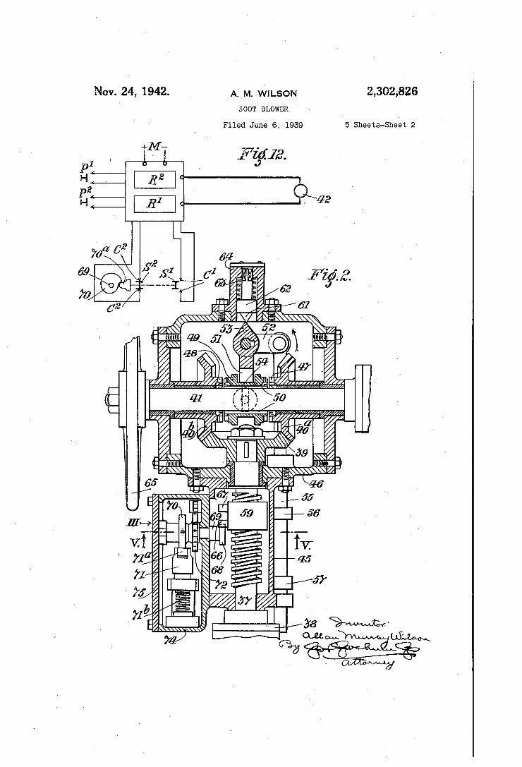
Fig. 1 is a plan of a1 soot-blower, parts on which the blower is mounted being shown in section‘.
Fig. 2 is a sectional plan of parts of the blower‘ operating assembly; Fig. 2 being drawn to a larger scale than Fig. 1.
Fig. 3 is a sectional elevation in the direction of the arrow III, Fig. 2.
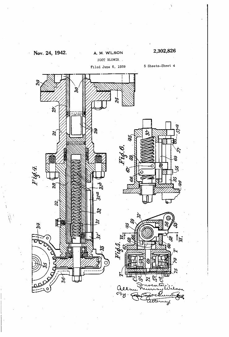
Fig. 4 is a section on‘ the-line IV-IV of Fig. 1'; Fig. 4 also being drawn‘ to a larger scale than Fig. 1.
Fig; 5 is a section on the line V’--V of Fig. 2. Fig, 6 is a section on the line VI-VI ofv Fig. 5. Figs. 7 to 11 are diagrams illustrative of the
action of switch-operating parts. Fig. 12 is a diagram illustrative of electrical
components provided in association with the soot blower.
Fig. 13 is an elevation of a soot-blower having itsv operating assembly arranged in a different manner from that according‘ to Figs. 1 to 4, and Fig. 14 is a plan of Fig. 13'.
Fig. 15 is an elevation of a soot-blower having its operating assembly arranged in yet a dif ferent' manner from that according to Figs. 1 to 4, the arrangement according to Fig. 15 in volving operation from a remote location;
Referring ?rstly to Figs. 1 to 4-, the soot-blower according thereto comprises a casing formed‘ mainly of three stationary parts 20, 2!, 22 which are rigidly inter-connected in axial oo-relation ship. The part 20 is attached to a so-called wall box 23 which is embedded in the wall 24 of a‘ steam-boiler. The part 20' is formed with a branch 25 which serves for the supply of clean ing'steamto thesoot-blower.. The steam ejector of the soot-blower consists of a nozzle 26, which is shown in the example as being double-ported (Fig. 1). The nozzle 26 is secured to one end of anozzle tube 21 whichv forms an extension of another tube 28. The nozzle tube 21 is formed with steam-inlet ports 29 which can be brought into register with ports 30‘ in permanent com munication with the steam-inlet branch 35. The extension tube 28 encloses a pair of in
terengaging screwed elements,_ one of which is a nut 51' secured in the tube‘ 28' and the-other of which is a screwed shaft 32~which is rotatable in a stationary location. ThescreW-threadedshaft 32' receives to»and'-fro rotational motion through screw-gears 33. 34' of which the gear" 33 is se cured to the shaft 32-‘ and of. whichthe gear: 33 is secured to a shaft 35'. The screw-gearsz33, 34. are .journalled in. agear. case. 36. which is adjust

2 able about the common axis of the casing 29, 2|, 22, the tubes 21, 28 and the rotatable parts 32, 33. The screw-threaded shaft 32 and nut 3| work
in combination with a cam device which controls the angular setting of the tube 28 and conse» quently the nozzle 25. In the example, the cam device consists of a cam slot 3la, 8H), which is formed in the casing part 22 and the follower of which is a pin or roller 3|’ mounted on the tube 28. The portion 3la of the cam slot is straight whereas the portion 3|b is helically or otherwise inclined. The arrangement is accord ingly such that if the ejector unit consisting of the parts 26—28 is caused to move axially by rotation of the screw-threaded shaft 32, the cam device will act to maintain the said unit against angular motion while the pin or roller 3|’ is in‘ the portion Sla but will permit or cause angular motion when the pin or roller 3i’ is in the por tion 311). The ports 29 and 39 constitute valve means
which operate automatically in the operation of the blower to open the supply of steam while the ejector 25 is advanced. axially into an oper ative zone beyond the wall box 23 and to shut off the supply while the ejector is retracted into an inoperative zone (see Fig. 1) in which it is shel tered from the heat of the furnace of the boiler. The arrangement is such that the ejector is ad vanced and retracted axially through the inop erative zone but is also turned angularly or rota tionally as it advances or is retracted through the operative zone. The soot-blower parts so far described are
known per se and accordingly the construction and operation thereof need not be described herein in further detail. A screw threaded shaft 31 constituting a re
versible blower-operating member is connected by a ?ange coupling 38 to the gear shaft 35. In the example under consideration the shaft 37 is horizontally arranged. Secured to the shaft 3‘! is a pinion wheel 39 which constantly meshes with two coaxial but diametrically opposed pin ions 48a, 45b journalled on a horizontal clutch shaft 4! which is driven unidirectionally by a small electric motor 42, for example a squirrel cage motor of 1/8 brake-horse-power and rotat able at 1400 revolutions per minute. The speed of the motor is reduced by reduction gearing which is not shown in the drawings but which is contained in a casing 43 forming part of the same structure as the motor, the reduction ratio being such that the clutch shaft 4| is rotated , unidirectionally at about 50 revolutions per min ute. The motor is mounted in juxtaposition to the soot-blower casing 26, 2!, 22 with the motor axis parallel to the casing axis (Fig. 1). The motor and reduction~gear structure is supported by a bracket 44 on the boiler wall. The operat ing shaft 37 is journalled in a casing 45 and the pinion gears are housed in a gear casing 46 which also is secured to the bracket 44 and to which the casing 45 is secured. Each of the opposed pinions 49a, 4917 has an
inwardly facing clutch 4'! or 49, and a double acting clutch 49 is disposed on the shaft 4| be tween said pinions to engage with the pinion clutches alternatively. The double-acting clutch is feathered at 50 to the clutch shaft 4| so as to rotate therewith, but the double-acting clutch 49 is slidable along the shaft 4| under the control of a clutch lever which is composed of three le Yer arms 5|, 52, 53 and is fulcrumed in the gear
‘2,302,826
(71
10
3 U
60
casing 46. The lever arm 5| is a fork which engages an annularly grooved portion 54 of the double-acting clutch 49. The second lever arm 52 is pivotally attached to a trigger rod 55 which is axially slidable in bearings provided for it in the casings 45, 46. The trigger rod 55 is provided with two spaced triggers 56, 51 which are arranged to co-operate with an intermediate striker 58 on a nut 59 (see Figs. 2, 5 and 6) which is in screw-threaded engagement with the operating shaft 31. A guide 60 secured to the casing 45 engages the striker 58 and thus main tains the nut 59 against rotational movement but permits the nut to move axially in one or other direction according to the direction in which the operating shaft 31 is rotated. The nut 59 constitutes an automatic reverser which acts on the clutch 49 through the triggers 56, 51 and the rod 55. The third lever arm 53 is a short projection presenting inclined faces which meet at an apex. This projection co-operates with a similarly formed projection 6| on a plung er 62 which is constantly pressed by a spring 63 and which is guided for movement to and from the projection 53 in a guide box 64. The clutch parts are so designed that, when
the double-acting clutch 49 is passing through its mid-position in relation to the two pinion clutches 41, 48 a small clearance space is left between the teeth of the double-acting clutch. and the teeth of the two pinion clutches (see Fig. 2). So far as concerns the parts already described
with reference to the drawings, the ejector unit 26—28 occupies substantially the retracted po sition in which it is shown in Fig. 1 when the soot blower is inoperative, and the nut 59 on the operating shaft 31 then occupies substantially the position in which it is shown in Figs. 2 and 6. The double-acting clutch 49 is then so lo cated that its teeth are fully in mesh with the clutch teeth 48 of the pinion 401). When the motor 42 is started, the clutch shaft
4| is rotated and rotates the operating shaft 31 in the direction to advance the ejector unit 2B—28 from its retracted position, so that the nozzle 26 will advance from the wall box 23 into the opera tive zone. At the same time, the nut 59 will be caused to advance along the shaft 31 towards the trigger 51. As the nozzle 26 nears its fully advanced position, the striker 58 will engage the trigger 51; and so the trigger rod 55 will be dis placed and will force the lever arm 52 to turn about its fulcrum and cause the lever arm 5| to withdraw the double-acting clutch from engage ment with the pinion clutch 48, thus freeing the pinions 49b and 39 from the motor drive. In consequence the operating shaft 3‘! and parts op era-ted therewith will instantly come to rest. How ever, the movement of the clutch lever 5 [-53 will be suf?cient to bring the apex of the projection '53 just past the dead centre position in relation 'to the co-operating projection 6|, with the result that the compressed spring 63 will force the clutch lever to continue its movement and bring the double-acting clutch into full engagement with the clutch teeth 41 of the opposite pinion 40a. Thus, a reversing action of the clutch parts is automatically brought about. After reversal, the pinion 40a, acting through
the pinion 39, will cause the operating shaft 31 to be rotated in the opposite direction, so that the ejector unit ‘will be retracted from its advanced position and the nut 59 will be caused to move
_ axially towards the trigger 56. When the ejector

2,302,826. '7 unit nears its fully retracted position the striker
58. engages the trigger 5.6 and displaces the trigger rod 55. in the direction to cause the double-acting clutch £39 to be retracted from engagement with the clutch teeth Ill of the pinion 40a. When the apex of the projection 53 has just passed the dead centre (as shown in Fig. 2, the lever then turning in the direction of the arrow). the com pressed spring '63 acting through the projection M on the projection 53 will cause the clutch lever to continue its movement sufficiently to bring the double-acting clutch 4-9 into full engagement with the clutch teeth 48 of the pinion 4332). Thus, another reversing action is brought about. The foregoing procedure will continue until the _
motor is stopped. It will have been noted that, as each stroke of
the ejector unit 26-28 is nearing its end, the action of the nut 59 and striker 58 upon the trigger rod 55 and clutch lever 5l——53. builds up sufficient energy by compressing the spring 63 to ensure that the reversing action of the double acting clutch 49 will be completed after the clutch driven parts have been cut-off from the motor drive. In effect, the double‘acting clutch follow~ i ing the completion of any stroke of the ejector unit is automatically brought into a condition to transmit the drive to the said unit and other driven parts in the next stroke, whether or not that stroke in fact takes, place.
Provision is made for varying the stroke of the steam-ejecting nozzle 2-8. In the example, the provision consists in arranging the trigger 51 ad justably on the trigger rod 55 and providing a pinching screw 51a (Fig. 6) to secure the trigger :r. E‘i in its position of adjustment. This ensures that it is the place» of reversal at the end of the advance stroke of the nozzle which is varied, the retracted position remaining constant. By mak ing such provision, the nozzle stroke is variable -:' between a maximum of about 7 inches and a minimum of about 3 inches. In order that the working parts of the soot
blower and of the operating assembly can be turned manually, a hand-wheel 65 is secured to one end of the clutch shaft 4 I.
Provision made whereby stoppage of the‘ blower-operating motor occurs automatically after completion of a predetermined number of nozzle strokes, this number in the example being six strokes. The arrangement is such that stoppage occurs only when the ejector has reached its fully retracted position following which, as already ex plained, the double~acting clutch 69 automatically re-engages the appropriate pinion clutch. This ensures that, following stoppage of the motor, the clutch mechanism is set all in readiness for the switching-on of the motor. The mechanism for causing the requisite timed
stoppage of the motor is operated by the reversing nut ‘59. As shown in Figs. 2, 5 and 6, the mecha nism includes two striker pins $6, 61 arranged at diiferen-t levels and horizontally offset from one another on the nut 59. These pins cooperate with a star wheel 63 which they are adapted to rotate intermittently, the star wheel having three arms equispaced 120° apart in conformity with the requirement that the nozzle shall per form six strokes. The star wheel 68 is secured to a shaft ~69 to which a cam '10 is secured. This cam has an active surface (see Fig. 3) which is formed with a uniform displacement contour ris ing in a curve from a point of minimum height to one of maximum height, both points being in
21
:30
60
tor-connected- by a- steep drop at ‘Mia. The follower 75
3 of the cam consists of a tappet ‘H with a cam engaging roller ‘Ha (Fig. 2), the tappet being forced towards the cam by a spring 'Hb. There is also secured to the cam shaft 69 a locating disc 12 which is formed with six equispaced notches 12a. A spring-urged detent 13 (Fig. 3) co-operates with the notches 12a, and is thus adapted to locate the cam in the successive posi tions into which it is turned by the action of the pin 66, 61. ' The tappet ‘H constitutes a mechanical support
for two bridge switches S’ and S2, respectively co operating with pairs of contacts C’, C’ and C2, C2 (Figs. 3 and 5). The. cam 10, disc 12, switches ‘S’, S2 and contacts C’, C2 are disposed in a casing 14 which is secured to the casing 45 of the oper ating shaft 31 and parts thereon. The cam shaft '59 is journalled in the casing 14 and extends therefrom into the proximity of the reversing nut 59. The casing ‘M is closed by a cover plate 15 (removed in Fig. 3). The respective contacts C", C2 are electrically connected to. four terminals T (Figs. 3 and 5) , the electric leads from these ter minals not being shown in the drawings. The striker pins 65, 61 serve to impart to the
cam 10 intermittent rotation in steps of 60° each and by virtue of this rotational motion the cam 18 controls the operation of the switches S’, S2. The operation of the striker pin 66, 61 will be described hereinafter with reference to Figs. '7 to 11.
Referring now to Fig. 12, there are diagram matically represented therein an assembly of electric and electro-magnetic components serv ing for the control of the starting and stopping of the blower-driving motor d2.
Referring to Fig. 12, R1 and R2 represent two electro-magnetic relays so connected in the elec tric circuit of the motor 42 that when either or both are closed the motor is thereby completely connected to the mains M and is thus in opera tion. The two switches 81, S2, the cam 10., and the tappet ll mechanically interconnecting the switches to operate in unison are also represent ed. P1 represents a starting push-button by de pression of which the motor is started. P2 repre sents a resetting push button by depression of which the electric and electro-magnetic compo nents are reset in condition for starting the motor should the blower have become stopped in the course of its sequence of operations. The assembly of electric and electro-magnetic
components diagrammatically represented and their connections are not claimed and moreover are known to those conversant with electrical control systems, and therefore details thereof are neither shown in the drawings nor described herein. The said assembly operates normally as fol
lows: When the blower is not in use and is set in readiness for operation, both relays R1, R.2 are open, the switch S1_also is open but the switch S2 is closed; this condition is represented by the drawings. To put the blower in operation, the
' push button P1 is depressed, the effect of which is that both relays R1, R2 close and the motor starts, The shaft 59 is now caused to rotate step-by-step, each step followingv a reversal ac tion by the clutch 49. Each step of the shaft 69 vcauses the cam 10 to displace the'tappet Ti and switches S1, S2, each of which is adapted to maintain sliding contact with the respective con tacts C1, C2 during a predetermined. extent of its displacement. At an intermediate state, the switch S1 is closed, but this has no effect on the

4- 2,302,826. other components shown. Next, the switch S2 is opened, and the only effect of this is to cut out the coil of the relay R1, which instantane ously opens. The relay R2 however remains closed. Finally, when the drop 13a of the cam reaches the tappet ‘H, the latter snaps back into its initial position under the action of spring 1 lb, thus closing the switch S2 and opening the switch S1. The effect of this is that the coil of the sec ond relay R2 is cut out, and this relay also opens, so that the motor circuit is broken and the motor stops. The drawings illustrate the blower parts at
the instant after the double-acting clutch 49 has passed through its mid-position and is on its way to engage the pinion clutch 48 in readiness for the next cycle of operations. At the instant illus trated, the tappet H has encountered the drop of the cam 75 and snapped into the position in which the motor circuit is open and the motor ‘ stopped. The action of the striker pins 66, 61 will now
be described with reference to Figs. 7 to 11 as starting from the position in which the parts operated by said pins are shown in the drawings; that is, as from the beginning of a complete cycle of operations. .
Fig. ‘7 shows the two pins 66, 61 starting to move towards the right (that is, in the direc tion of movement of the striker 58- towards the I‘ trigger 51 as viewed in Fig. 6), The steam~eject~ ing nozzle 26 is then starting to advance from its inoperative position. It will be seen that the top pin 66 will move clear of the star wheel 58 (on the cam shaft 69) whereas the bottom pin 6‘! ' will engage it.
Figs. 8 and 9 show how the top pin 65 passes clear of the star wheel 68 and how the bottom pin 61 engages the star wheel and turns it 60° coun ter-clockwise. The pins 63, B7 idly continue their motion to the right until the double-acting clutch 54 is changed over, the nozzle 26 then be ing fully advanced. Thereafter, the pins 65, 67 return to the left.
Fig. 10 shows that, on the return of the pins, the upper pin 66 will engage the star wheel whereas the bottom pin 51 will move clear there of. Fig. 11 shows the upper pin turning the star wheel through a further 60° counterclockwise, the turning action being completed when the ex treme Fig. ‘7 position is again reached. At this position the clutch 54 is again changed over. Thereafter, the pins 56, 5'! move towards the right and the nozzle again advances, Thus, in one complete movement of the pins
to the right and back again to the left, the star wheel receives in all 120° from their successive actions. Therefore, when three of these com plete movements have been performed (that is, six strokes of the nozzle) the star wheel and the switch cam 13 have turned through 360°, and so the drop of the cam becomes effective. At that instant, the switch mechanism operates to cut out the blower-operating motor as already de scribed with reference to Fig. 12. The pins and the star-wheel then occupy their Fig. '7 position. In the arrangement according to Figs. 1 to 4,
the motor 42 is arranged in juxtaposition to the soot-blower proper with the motor axis parallel to the axis of the ejector unit 25-28 and the parts associated therewith, the reversing mecha nism contained in and associated with the casing 45 being arranged to cross perpendicularly from
_ ,the gear casing “to the soot-blower. There is
10
40
65
75
the usual blower mounting 23 on the boiler wall and a separate mounting 44 thereon for the motor and associated blower-operating parts. The ar rangement may however be such that need for such a separate mounting is obviated. For ex ample, one such other arrangement is illustrated by Figs. 13 and 14, which will now be described. Referring to Figs. 13 and 14, in the arrange
ment illustrated thereby, the motor 42 and clutch gearing associated therewith are arranged above the soot-blower proper with their axis cross wise of the axis of the blower, the axis of the shaft 35 and the parts in the casing 45 being in this arrangement parallel to the blower axis. The individual parts are in general the same as in ac cordance with Figs. 1 to 4 and the exposed parts are denoted by the same reference numerals. However, as regards the gearing interconnecting the shafts 32 and 35, as these shafts are now par allel, screw-gears such as 33, 34 (Fig. 4) are no longer employed but are replaced by any of the various forms of gearing suitable for transmit ting a drive between parallel shafts without slip. The motor and gear casing are mounted in the arrangement according to Figs. 13 and 14 on a bracket 80 secured to the casing part 20, so that the motor, clutch gearing and reversing mecha nism require for their accommodation substan tlally no more space on the boiler wall than a corresponding hand-operated soot-blower. In the arrangements already described, the
motor forms part of the same structural assembly as the soot-blower proper and the intermediate gearing. The arrangement, however, may be such that the soot-blower alone is mounted in the appropriate position on the boiler wall while the motor and clutch gearing are mounted in a re mote location; for example, at some convenient place, say, on the ?oor. An example of such an arrangement is illustrated by Fig. 15. Referring to Fig. 15, the parts of the soot
blower proper and the operating assembly are substantially the same as already described with reference to Figs. 1 to 4, and accordingly the ex posed parts in Fig. 15 are given the same ref erence numerals. As shown, the soot-blower proper is arranged high above the motor, clutch gearing and reversing mechanism. The casing 45 is so arranged that the shaft 35 is vertical. Cor respondingly, the casing 45 and the mechanism contained in and associated therewith is arranged vertically upon the clutch gear case 46. The shaft 35, instead of being connected directly to the coupling 38 on the operating shaft 31, is con nected thereto through shafting 90, 9|, the re spective parts of which are universally coupled together at 92. The motor and gear casing are mounted on a sole-plate 93. In any of the arrangements described, there
may be provided in association with the operat ing shaft 31, for operation thereby, an indicator (not shown) comprising a pointer which moves to-and-fro along a stationary graduated scale to indicate the position of the ejector in its range of movement. Such a pointer may be on the nut 59.
I claim: 1. A sootblower-operating assembly compris
ing a unidirectional rotary motor drive, a revers ible power-transmitting connection driven by said drive, a reversing clutch interposed between said drive and said connection, means operatively con nected to said power-transmitting connection for actuation thereby about the end of each one of

2,302,826 several recurring periods of operation of said con nection to actuate said clutch and thus reverse the direction in which said connection is driven and means for switching-off said drive, said switching-off means being operatively connect ible to said clutch for operation thereby to effect switching-off on completion of a plurality of said periods.
2. A sootblower-operating assembly comprising a unidirectional rotary motor drive, a reversible power-transmitting connection driven for a series of periods by said drive, reversing mechanism in terposed between said drive and said connection, means actuating said reversing mechanism at the end of each of said periods to reverse the direc tion in which said connection is driven and means operated under the control of said reversing mechanism to switch-01f said drive on comple tion of said series of periods.
3. A sootblower-operating assembly comprising a unidirectional rotary motor drive, reversing mechanism comprising opposed bevel pinions journalled coaxially of said drive and respectively provided with clutch elements and a double-act ing clutch driven by said drive and displaceable axially thereof to engage said clutch elements al ternatively, a bevel gearwheel meshing with both said bevel pinions, a reversible power-transmit ting connection driven for a series of periods by said gearwheel and including a rotatable screw- 5 threaded shaft, a nutlike member engaging said shaft, means constraining said member to travel along said shaft on rotation thereof throughout each of said periods, and a trigger assembly adapted for operation by said nutlike member at - opposite ends of the travel of said member to ac tuate said double-acting clutch at the end of each of said periods to reverse the direction in which said connection is driven and means operated un der the control of said reversing mechanism to switch-off said drive on completion of said series of periods.
4. A sootblower-operating assembly comprising a unidirectional rotary motor drive, a reversible power-transmitting connection driven by said drive, reversing mechanism including a reversing clutch interposed between said drive and said connection, said clutch being driven by said drive, gears respectively arranged to rotate said con nection in opposite directions, said clutch being adapted for alternative engagement with said gears, means adapted to bring said clutch into engagement with one of said gears after a pre determined extent of operation of said connec tion through the other of said gears, a device adapted to switch-o? said drive and means oper atively connectible with said clutch so as to be operated by successive transpositions thereof to actuate said device and effect switching-off on completion of a predetermined plurality of such transpositions. .
5. A sootblower-operating assembly compris ing a unidirectional rotary motor drive, a re versible power-transmitting connection driven by said drive, reversing mechanism including a re versing clutch interposed between said drive and said connection, said clutch being driven by said drive, gears respectively arranged to rotate said connection in opposite directions, said clutch being adapted for alternative engagement with
40
50
60
65
70
5 said gears, means adapted to transpose said clutch from one of said gears to the other after each of recurrent periods of operation of said connection, a device adapted to switch off said drive and means operated by said connection to operate said device on completion of a prede termined plurality of such periods of operation.
6. A sootblower-operating assembly comprising a unidirectional rotary motor drive, a reversible power-transmitting connection driven by said drive and applicable to the sootblower, reversing mechanism interposed between said drive and said connection, means adapted to actuate said reversing mechanism at the end of periods of op eration by said drive of said connection to re verse the direction in which said connection is driven, a device adapted to switch off said drive and means for operating said device on comple tion of a, predetermined plurality of said periods of operation of said connection.
7. A sootblower-operating assembly comprising a unidirectional rotary motor drive, a reversible power-transmitting connection between said drive and the sootblower, said connection including a rotatable screw-threaded shaft, a nutlike member engaging said shaft, means constraining said member to travel along said shaft on rotation thereof in either direction, a trigger assembly adapted for operation by said nutlike member to effect reversal of said connection at opposite ends of the travel of said member, so that said shaft performs recurrent periods of rotation in succes sively opposite directions, and mechanism oper ated by said nutlike member to switch off said drive on completion of a predetermined number of said periods.
8. A sootblower-operating assembly comprising a unidirectional rotary drive, a power-transmit ting connection, including reversing mechanism between said drive and the sootblower, a member driven to-and-fro by a part of said connection, a cam operated stepwise by said member so as to perform a, plurality of operations corresponding to a predetermined cycle of operations of the sootblower, and means for switching off said drive under the control of said cam on completion of said plurality of operations.
9. A sootblower-operating assembly comprising a unidirectional rotary drive, a power-transmitting connection including reversing mechanism be tween said drive and the sootblower, said connec tion including a rotatable screw-threaded shaft, a nut-like member engaging said shaft, means con straining said member to travel along said shaft on rotation thereof in either direction, a cam operated stepwise by said nutlike member so as to perform a plurality of operations correspond ing to a predetermined cycle of operations of the sootblower and means for switching off said drive under the control of said cam on completion of said plurality of operations.
10. A sootblower-operating assembly as claimed in claim 7 wherein the said trigger assembly com prises an axially displaceable trigger rod carrying spaced triggers and a striker on said nutlike mem ber and intermediate said triggers, and wherein one of said triggers which effects reversal of the power-transmitting connection is adjustable to vary the duration of said operation.
ALLAN MURRAY WILSON.