notice: this manual is to remain with truck after … this manual is to remain with truck after pump...
TRANSCRIPT
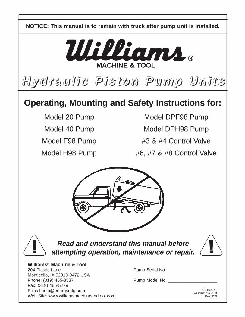
NOTICE: This manual is to remain with truck after pump unit is installed.
H y d r a u l i c P i s t o n P u m p U n i t sH y d r a u l i c P i s t o n P u m p U n i t s
Operating, Mounting and Safety Instructions for:
Read and understand this manual beforeattempting operation, maintenance or repair.
Williams® Machine & Tool204 Plastic Lane Pump Serial No. ____________________Monticello, IA 52310-9472 USAPhone: (319) 465-3537 Pump Model No. ____________________Fax: (319) 465-5279E-mail: [email protected] Site: www.williamsmachineandtool.com
Model 20 Pump
Model 40 Pump
Model F98 Pump
Model H98 Pump
Model DPF98 Pump
Model DPH98 Pump
#3 & #4 Control Valve
#6, #7 & #8 Control Valve
MACHINE & TOOL
SAFBOOK1Williams® p/n 2183
Rev. 9/09
!!
Read and understand this manual before
attempting operation, maintenance or repair
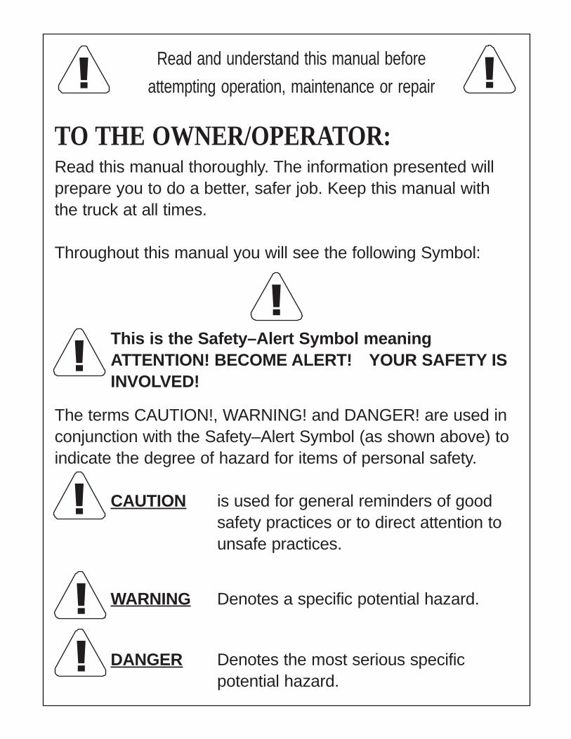
TO THE OWNER/OPERATOR:Read this manual thoroughly. The information presented willprepare you to do a better, safer job. Keep this manual withthe truck at all times.
Throughout this manual you will see the following Symbol:
This is the Safety–Alert Symbol meaningATTENTION! BECOME ALERT! YOUR SAFETY ISINVOLVED!
The terms CAUTION!, WARNING! and DANGER! are used inconjunction with the Safety–Alert Symbol (as shown above) toindicate the degree of hazard for items of personal safety.
CAUTION is used for general reminders of goodsafety practices or to direct attention tounsafe practices.
WARNING Denotes a specific potential hazard.
DANGER Denotes the most serious specificpotential hazard.
! !
!
!
!!
!
TABLE OF CONTENTS
TO THE OWNER / OPERATOR .................................... INSIDE FRONT COVER
CHECKLISTS ..................................................................................................... 2
GENERAL INFORMATION................................................................................. 2
SAFETY INFORMATION
SAFETY DECALS........................................................................... 3 - 4
SAFETY DECAL LOCATIONS........................................................ 5 - 8
PUMP OPERATIONAL SAFETY ......................................................... 9
OPERATING INSTRUCTIONS
PREFACE .......................................................................................... 10
OPERATING INSTRUCTION .............................................................11
INSTALLATION INSTRUCTION CHECKLIST ................................... 13
INSTALLATION AND SERVICE INSTRUCTIONS
CONTROL CABLE INSTALLATION............................................ 14 - 18
PUMP ONLY REMOVAL............................................................. 19 - 20
PUMP PARTS LISTS .................................................................. 21 - 31
PUMP ONLY INSTALLATION ..................................................... 32 - 33
VALVE ONLY REMOVAL
3 - BOLT VALVE .......................................................... 34 - 35
3 - BOLT VALVE PARTS LIST..................................... 36 - 37
4 - BOLT VALVE .......................................................... 38 - 40
4 - BOLT VALVE PARTS LIST..................................... 41 - 43
VALVE ONLY INSTALLATION
3 - BOLT VALVE .......................................................... 44 - 45
4 - BOLT VALVE .......................................................... 46 - 48
WARRANTY...................................................................... INSIDE BACK COVER
1
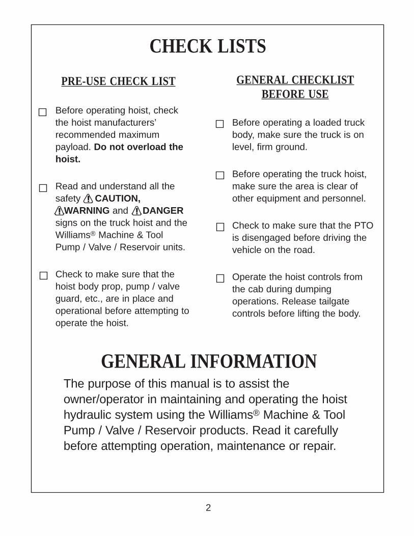
CHECK LISTS
GENERAL INFORMATIONThe purpose of this manual is to assist theowner/operator in maintaining and operating the hoisthydraulic system using the Williams® Machine & ToolPump / Valve / Reservoir products. Read it carefullybefore attempting operation, maintenance or repair.
PRE-USE CHECK LIST
Before operating hoist, checkthe hoist manufacturers’recommended maximumpayload. Do not overload thehoist.
Read and understand all thesafety CAUTION, WARNING and DANGERsigns on the truck hoist and theWilliams® Machine & ToolPump / Valve / Reservoir units.
Check to make sure that thehoist body prop, pump / valveguard, etc., are in place andoperational before attempting tooperate the hoist.
GENERAL CHECKLISTBEFORE USE
Before operating a loaded truckbody, make sure the truck is onlevel, firm ground.
Before operating the truck hoist,make sure the area is clear ofother equipment and personnel.
Check to make sure that the PTOis disengaged before driving thevehicle on the road.
Operate the hoist controls fromthe cab during dumpingoperations. Release tailgatecontrols before lifting the body.
!!!
2
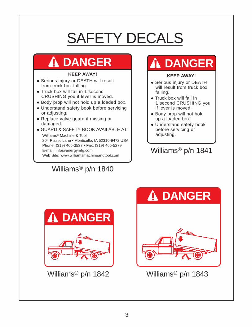
KEEP AWAY!
• Serious injury or DEATH will result from truck box falling.
• Truck box will fall in 1 second CRUSHING you if lever is moved.
• Body prop will not hold up a loaded box.
• Understand safety book before servicing or adjusting.
• Replace valve guard if missing or damaged.
• GUARD & SAFETY BOOK AVAILABLE AT:Williams® Machine & Tool204 Plastic Lane • Monticello, IA 52310-9472 USAPhone: (319) 465-3537 • Fax: (319) 465-5279E-mail: [email protected] Site: www.williamsmachineandtool.com
KEEP AWAY!
• Serious injury or DEATHwill result from truck boxfalling.
• Truck box will fall in1 second CRUSHING youif lever is moved.
• Body prop will not holdup a loaded box.
• Understand safety bookbefore servicing oradjusting.
SAFETY DECALS
Williams® p/n 1841
Williams® p/n 1842 Williams® p/n 1843
DANGER!
Williams® p/n 1840
DANGER!
DANGER!
DANGER!
3
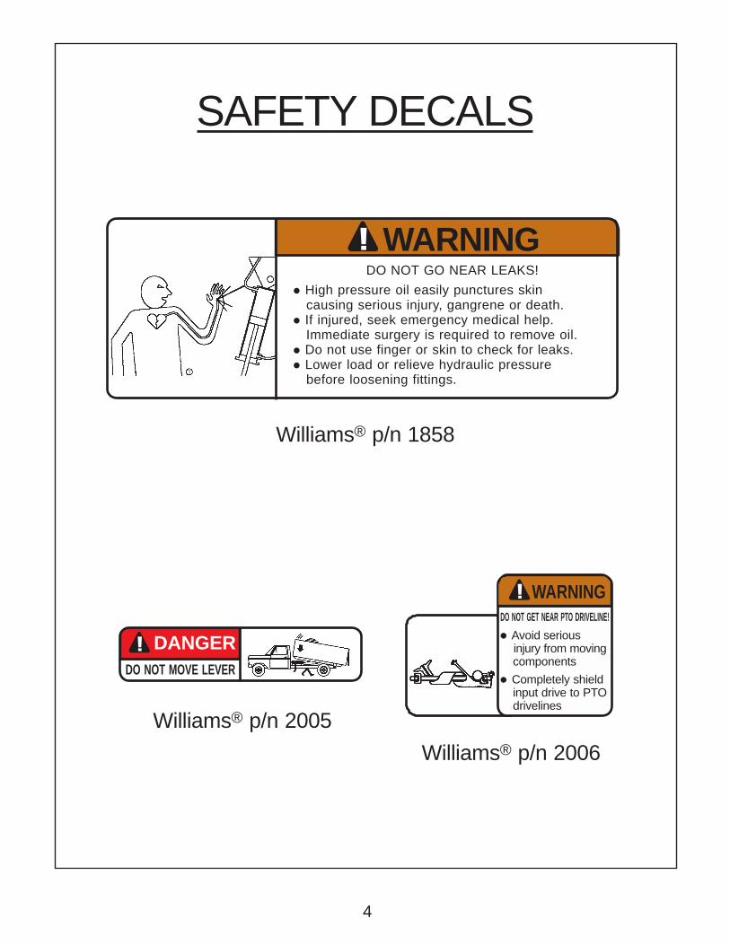
DO NOT GO NEAR LEAKS!
• High pressure oil easily punctures skin causing serious injury, gangrene or death.• If injured, seek emergency medical help. Immediate surgery is required to remove oil.• Do not use finger or skin to check for leaks.• Lower load or relieve hydraulic pressure before loosening fittings.
WARNING
DO NOT MOVE LEVER
DANGER
WARNINGDO NOT GET NEAR PTO DRIVELINE!
• Avoid serious injury from moving
components
• Completely shieldinput drive to PTOdrivelines
Williams® p/n 1858
Williams® p/n 2005
Williams® p/n 2006
SAFETY DECALS
!
!
!
4
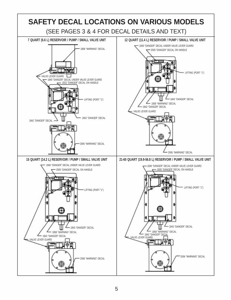
SAFETY DECAL LOCATIONS ON VARIOUS MODELS(SEE PAGES 3 & 4 FOR DECAL DETAILS AND TEXT)
7 QUART (6.6 L) RESERVOIR / PUMP / SMALL VALVE UNIT 12 QUART (11.4 L) RESERVOIR / PUMP / SMALL VALVE UNIT
15 QUART (14.2 L) RESERVOIR / PUMP / SMALL VALVE UNIT 21-60 QUART (19.9-56.8 L) RESERVOIR / PUMP / SMALL VALVE UNIT
1858 “WARNING” DECAL
LIFTING (PORT “1”)
1842 “DANGER” DECAL1842 “DANGER” DECAL
2022 “DANGER” DECAL ON HANDLE
VALVE LEVER GUARD1840 “DANGER” DECAL UNDER VALVE LEVER GUARD
2006 “WARNING” DECAL
VALVE LEVER GUARD
LIFTING (PORT “1”)
2005 “DANGER” DECAL ON HANDLE
1840 “DANGER” DECAL UNDER VALVE LEVER GUARD
2006 “WARNING” DECAL
1843 “DANGER” DECAL
1858 “WARNING” DECAL1842 “DANGER” DECAL
2006 “WARNING” DECAL
1840 “DANGER” DECAL UNDER VALVE LEVER GUARD
1843 “DANGER” DECAL
1858 “WARNING” DECAL1842 “DANGER” DECAL
2005 “DANGER” DECAL ON HANDLE
LIFTING (PORT ”1”)
VALVE LEVER GUARD
2006 “WARNING” DECAL
1840 “DANGER” DECAL UNDER VALVE LEVER GUARD
1843 “DANGER” DECAL
1858 “WARNING” DECAL1842 “DANGER” DECAL
2005 “DANGER” DECAL ON HANDLE
LIFTING (PORT ”1”)
VALVE LEVER GUARD
5

SAFETY DECAL LOCATIONS ON VARIOUS MODELS(SEE PAGES 3 & 4 FOR DECAL DETAILS AND TEXT)
12 QUART (11.4 L) RESERVOIR / PUMP / LARGE VALVE UNIT 15 QUART (14.2 L) RESERVOIR / PUMP / LARGE VALVE UNIT
21-60 QUART (19.9-56.8 L) RESERVOIR / PUMP / LARGE VALVE UNIT ALL RESERVOIRS / PUMP / DUAL LARGE VALVE UNITS
2006 “WARNING” DECAL
1858 “WARNING” DECAL
1843 “DANGER” DECAL
1840 “DANGER” DECAL UNDER VALVE LEVER GUARD
VALVE LEVER GUARDLIFTING PORT ”B”
2005 “DANGER” DECAL ON HANDLE
2006 “WARNING” DECAL
1840 “DANGER” DECAL UNDER VALVE LEVER GUARD
1843 “DANGER” DECAL
1858 “WARNING” DECAL1842 “DANGER” DECAL
2005 “DANGER” DECAL ON HANDLE
LIFTING (PORT ”1”)
VALVE LEVER GUARD
1843 “WARNING” DECAL
2005 “DANGER” DECAL ON HANDLE
1843 “DANGER” DECAL
1840 “DANGER” DECAL UNDER VALVE LEVER GUARD
VALVE LEVER GUARD
LIFTING PORT ”B”
1858 “WARNING” DECAL
2006 “WARNING” DECAL
1858 “WARNING” DECAL
LIFTING PORT “B”
1840 “DANGER” DECAL
VALVE LEVER GUARD
LIFTING PORT ”B”
2005 “DANGER” DECAL ON BOTH HANDLES1843 “DANGER” DECAL
6
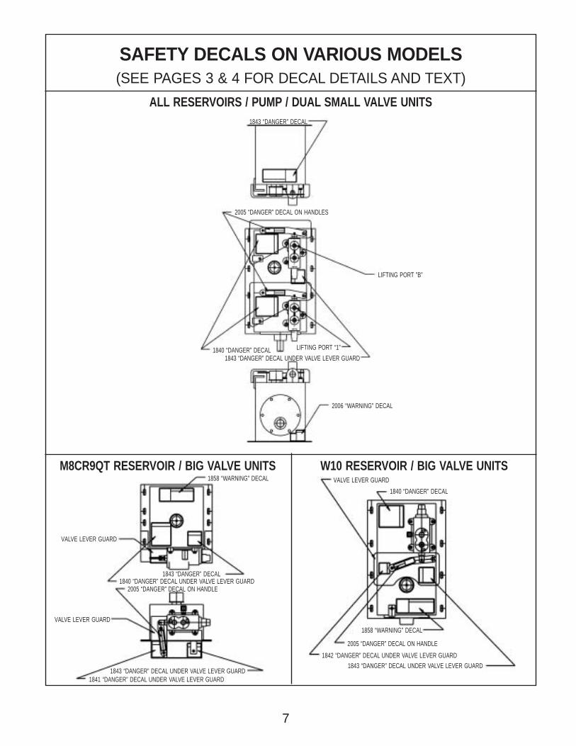
SAFETY DECALS ON VARIOUS MODELS(SEE PAGES 3 & 4 FOR DECAL DETAILS AND TEXT)
ALL RESERVOIRS / PUMP / DUAL SMALL VALVE UNITS
M8CR9QT RESERVOIR / BIG VALVE UNITS W10 RESERVOIR / BIG VALVE UNITS
2006 “WARNING” DECAL
2005 “DANGER” DECAL ON HANDLES
1843 “DANGER” DECAL
1840 “DANGER” DECAL LIFTING PORT “1”
LIFTING PORT ”B”
1843 “DANGER” DECAL UNDER VALVE LEVER GUARD
2005 “DANGER” DECAL ON HANDLE
1841 “DANGER” DECAL UNDER VALVE LEVER GUARD
VALVE LEVER GUARD
1858 “WARNING” DECAL
1843 “DANGER” DECAL
VALVE LEVER GUARD
1840 “DANGER” DECAL UNDER VALVE LEVER GUARD
1843 “DANGER” DECAL UNDER VALVE LEVER GUARD
VALVE LEVER GUARD
1840 “DANGER” DECAL
1842 “DANGER” DECAL UNDER VALVE LEVER GUARD
1843 “DANGER” DECAL UNDER VALVE LEVER GUARD
2005 “DANGER” DECAL ON HANDLE
1858 “WARNING” DECAL
7
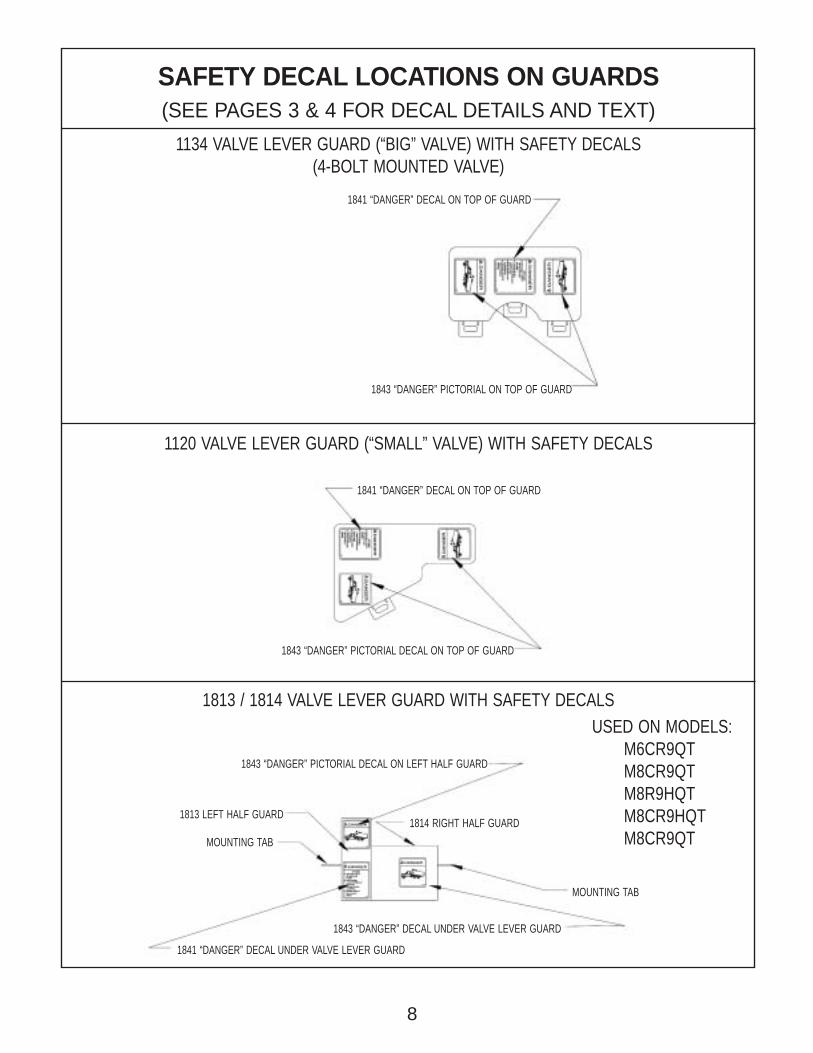
SAFETY DECAL LOCATIONS ON GUARDS(SEE PAGES 3 & 4 FOR DECAL DETAILS AND TEXT)
1134 VALVE LEVER GUARD (“BIG” VALVE) WITH SAFETY DECALS(4-BOLT MOUNTED VALVE)
1813 / 1814 VALVE LEVER GUARD WITH SAFETY DECALS
1120 VALVE LEVER GUARD (“SMALL” VALVE) WITH SAFETY DECALS
1841 “DANGER” DECAL ON TOP OF GUARD
1843 “DANGER” PICTORIAL ON TOP OF GUARD
1843 “DANGER” PICTORIAL DECAL ON TOP OF GUARD
1841 “DANGER” DECAL ON TOP OF GUARD
1843 “DANGER” PICTORIAL DECAL ON LEFT HALF GUARD
MOUNTING TAB
1813 LEFT HALF GUARD
1843 “DANGER” DECAL UNDER VALVE LEVER GUARD
MOUNTING TAB
1841 “DANGER” DECAL UNDER VALVE LEVER GUARD
1814 RIGHT HALF GUARD
8
USED ON MODELS:M6CR9QTM8CR9QTM8R9HQTM8CR9HQTM8CR9QT
CAUTIONUnless specifically stated in writing by Williams®, Williams®’ products are not approved for, and notwarranted when used in: high-cycle industrial applications, aerospace applications, applications that
lift people, or for any application that may place people in dangerous positions during operation.
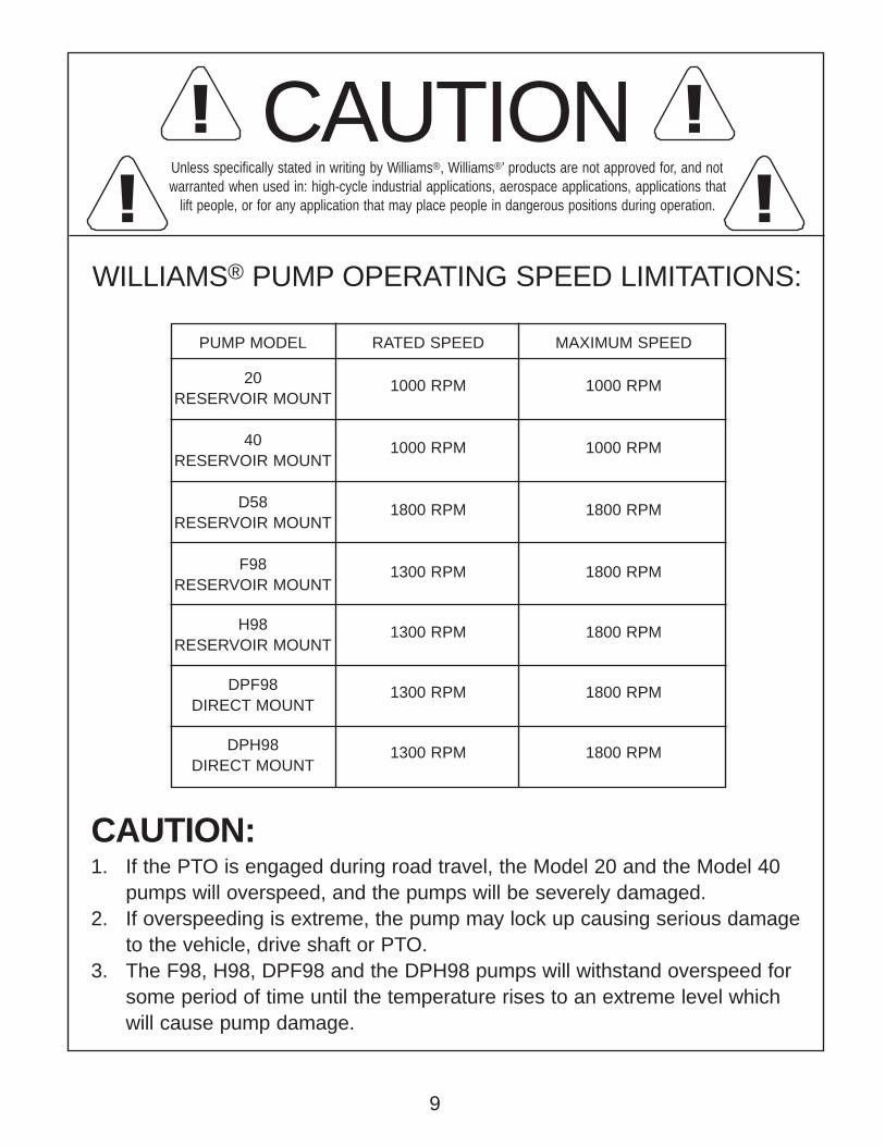
WILLIAMS® PUMP OPERATING SPEED LIMITATIONS:
CAUTION:1. If the PTO is engaged during road travel, the Model 20 and the Model 40
pumps will overspeed, and the pumps will be severely damaged.2. If overspeeding is extreme, the pump may lock up causing serious damage
to the vehicle, drive shaft or PTO.3. The F98, H98, DPF98 and the DPH98 pumps will withstand overspeed for
some period of time until the temperature rises to an extreme level whichwill cause pump damage.
PUMP MODEL RATED SPEED MAXIMUM SPEED
20RESERVOIR MOUNT
1000 RPM 1000 RPM
40RESERVOIR MOUNT
1000 RPM 1000 RPM
D58RESERVOIR MOUNT
1800 RPM 1800 RPM
F98RESERVOIR MOUNT
1300 RPM 1800 RPM
H98RESERVOIR MOUNT
1300 RPM 1800 RPM
DPF98DIRECT MOUNT
1300 RPM 1800 RPM
DPH98DIRECT MOUNT
1300 RPM 1800 RPM
! !! !
9

OPERATING INSTRUCTIONS
PREFACE
INSTALLATION (NEW OR REPLACEMENT)
1. Before beginning any installation work, make sure that the truck box is empty –
if necessary, empty the load. Make sure the empty truck box is properly blocked
by using the body props on the hoist unit as well as blocks under the hoist
frame. Then, from the cab (not from under the truck box) push the control cable
in to lower the truck box onto the body props and blocks to make sure the body
props and blocks will hold the empty truck box safely.
2. Install the pump/valve/reservoir unit in line with the PTO output to meet the PTO
driveline manufacturers’ position and angle recommendations.
3. Use a fully shielded PTO driveline in the installation to avoid serious injury from
rotating components.
4. Install the control cable to the pump/valve/reservoir unit per the control cable
installation instructions on pages 14-18.
5. Install the hydraulic hoses to the hoist unit using the port "B" on the 4-bolt mount
control valve and port “1” on the 3-bolt mount control valve to the lifting port on
the hoist cylinder. Use hydraulic hoses with a working pressure rating equal to
or greater than the highest pressure at which the system will be operating.
6. Fill reservoir to the recommended level with automobile automatic transmission
fluid (ATF).
7. Properly install the control valve guard or guards before operating the hoist
system.
NOTE: Use the installation and maintenance check list that follows (page 13) before the
operation of the hoist system.
!
10
!
OPERATING INSTRUCTIONS
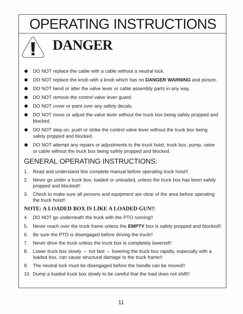
DANGER
• DO NOT replace the cable with a cable without a neutral lock.
• DO NOT replace the knob with a knob which has no DANGER WARNING and picture.
• DO NOT bend or alter the valve lever or cable assembly parts in any way.
• DO NOT remove the control valve lever guard.
• DO NOT cover or paint over any safety decals.
• DO NOT move or adjust the valve lever without the truck box being safely propped andblocked.
• DO NOT step on, push or strike the control valve lever without the truck box beingsafely propped and blocked.
• DO NOT attempt any repairs or adjustments to the truck hoist, truck box, pump, valveor cable without the truck box being safely propped and blocked.
GENERAL OPERATING INSTRUCTIONS:1. Read and understand this complete manual before operating truck hoist!!
2. Never go under a truck box, loaded or unloaded, unless the truck box has been safelypropped and blocked!!
3. Check to make sure all persons and equipment are clear of the area before operatingthe truck hoist!!
NOTE: A LOADED BOX IS LIKE A LOADED GUN!!
4. DO NOT go underneath the truck with the PTO running!!
5. Never reach over the truck frame unless the EMPTY box is safely propped and blocked!!
6. Be sure the PTO is disengaged before driving the truck!!
7. Never drive the truck unless the truck box is completely lowered!!
8. Lower truck box slowly – not fast – lowering the truck box rapidly, especially with aloaded box, can cause structural damage to the truck frame!!
9. The neutral lock must be disengaged before the handle can be moved!!
10. Dump a loaded truck box slowly to be careful that the load does not shift!!
11
12
TYPI
CAL
GUAR
DED
PTO
SHAF
T IN
STAL
LATI
ON
PTO
DRIV
E UN
IT M
OUNT
ED O
N TR
ANSM
ISSI
ON
WIL
LIAM
S® M
ACHI
NE &
TOO
L
PTO
DRIV
ENPU
MP/
RESE
RVOI
R/VA
LVE
UNIT
ROTA
TING
DRI
VELI
NECO
NTAC
T CA
N CA
USE
DEA T
HKE
EP A
WAY
DO N
OT O
PERA
TE W
ITHO
UT:
• ALL
DRI
VELI
NE, T
RACT
OR A
ND E
QUIP
MEN
T SH
IELD
S IN
PLA
CE• D
RIVE
LINE
SEC
UREL
Y A
TTAC
HED
AT B
OTH
ENDS
• DRI
VELI
NE S
HIEL
DS T
HAT
TURN
FRE
ELY
ON D
RIVE
LINE

OPERATING INSTRUCTIONSINSTALLATION & MAINTENANCE CHECK LIST
INSTALLATION CHECK LIST:
CHECK OFF AFTER PROPER INSTALLATION IS COMPLETE:
FIRST DANGER: SAFELY PROP, BLOCK OR BRACE TRUCK BOX BEFOREBEGINNING INSTALLATION.
1. Pump/valve/reservoir installed in line with PTO to meet driveline specifications. 2. Use a fully shielded PTO driveline installed per manufacturers’ specifications. 3. Hydraulic hoses installed to the hoist from the proper port. 4. The cable casing clamps are not overtightened binding the wire core (see Fig. C Pg. 17). 5. The exposed cable wire length is no longer than 1/4" (6.35 mm) (see Fig. C Pg. 17). 6. The cable casing is clamped/aligned to minimize pushing force (see Fig. C Pg. 17). 7. The wire clamp on the valve lever and the cable casing clamp are capable of
swiveling to self-align properly (see Fig. C Pg. 17). 8. No bend in the cable is less than 10" (25.4 cm) (see Fig. A Pg. 16). 9. The neutral lock is detented when the valve spool is in the neutral or hold position
(see Fig. A Pg. 16)10. The knob with DANGER sign and picture are installed on the cable.11. The cable is routed away from catalytic converters, tailpipes, exhaust manifolds, or
mufflers. These can melt the outer casing exposing the cable wire, and possibly causing failure.
12. The outer casing is not crushed or routed where moving parts may crush it during use.
13. One cable casing tie per bend or per 3' (91.4 cm) of cable length is securely fastened adequately in secure parts of the frame.
14. The valve lever guard is fastened securely according to the installation instructions.
WEEKLY MAINTENANCE CHECK LIST: 1. Are all tie downs secure on the cable? If not, replace. 2. Is the cable wire moving freely after lubrication? If not, repair or replace. 3. Is the valve lever guard and all safety signs in place, clean and legible? If not,
replace immediately. 4. Is the cable casing wearing through and allowing moisture and rust to corrode the
cable assembly? If so, replace. 5. Can the cable casing clamp and cable wire clamp on the valve lever still swivel? If
not, lubricate both. 6. Is the neutral lock button releasing freely after lubrication, and is the cable locked
when the valve is in the neutral (hold) position? If not, adjust until proper or replace. 7. Check the tightness of the cable wire clamp bolt to be certain it does not slide on the
wire. If sliding, tighten or replace. 8. Check hydraulic reservoir fluid level. Add fluid if needed. Always use automotive
automatic transmission fluid (ATF).
!
✓
13

Williams® p/n 1843
DANGER!KEEP AWAY!
• Serious injury or DEATH will result from truck box falling.
• Truck box will fall in 1 second CRUSHING you if lever is moved.
• Body prop will not hold up a loaded box.
• Understand safety book before servicing or adjusting.
• Replace valve guard if missing or damaged.
• GUARD & SAFETY BOOK AVAILABLE AT:Williams® Machine & Tool204 Plastic Lane • Monticello, IA 52310-9472 USAPhone: (319) 465-3537 • Fax: (319) 465-5279E-mail: [email protected] Site: www.williamsmachineandtool.com
DANGER!
Williams® p/n 1840
!
! DANGER Cables used on truck hoist applications must be of the neutral locktype to meet OSHA Standard 1926. Do not replace your control cableassembly without the neutral lock feature. The neutral lock on thecontrol cable assembly protects those in the truck box area fromaccidental actuation and serious injury or death.
DANGER Operator or mechanics shall follow instructions to prevent improperinstallation that can cause cable to kink. Failure to do so shall resultin death or serious injury.
NOTE: Cable must be properly installed and checked for proper operation(see Fig. B Pg. 17) completely before hydraulic lines are installed tocontrol valve.
THESE INSTRUCTIONS MUST STAY WITH THE TRUCKTO WARN FUTURE OWNERS AND OPERATORS!
INSTALLATION & SERVICEINSTRUCTIONS
CONTROL CABLE INSTALLATIONIMPORTANT INSTRUCTIONS
14

!
INSTALLATION & SERVICEINSTRUCTIONS
CONTROL CABLE INSTALLATION INSTRUCTIONS
Before beginning any installation work, make sure that the truck box is empty –if necessary, empty the load. Make sure the empty truck box is properlyblocked by using the body props on the hoist unit as well as blocks under thehoist frame. Then, from the cab (not from under the truck box) push the controlcable in to lower the truck box onto the body props and blocks to make surethe body props and blocks will hold the empty truck box safely.
1. Mount the control cable to the vehicle with special attention that no bends aresharper than a 10 inch (25.4 cm) radius (see Fig. A).
2. Be certain that the cable plunger is locked in the neutral lock groove as shownin Figure A.
3. Route the control cable casing away from catalytic converters, tailpipes,exhaust manifolds or mufflers. These can melt the outer casing exposing thecable wire, and possibly causing failure.
4. Install the stroke limiting spacer nut on the plunger of the control assembly inthe cab of the truck to limit the travel of the control cable wire when pushed in(see Fig. D). DANGER failure to install the spacer nut can cause thecontrol cable wire to kink from over-travel and the cable will not operate prop-erly. Failure to follow these instructions may result in serious injury or death.
5. Install the control cable to the control valve and tighten the casing clamp swiveland wire clamp swivel according to Figure C (Pg. 17). Be certain both clampsare free to swivel after tightening and that the wire will freely travel aftertightening. Also be certain that there is no more than 1/4" (6.35 mm) of ex-posed wire with the control lever in the up position. With the control valve inneutral – from the truck cab – test the control cable assembly to be certainthe wire will travel the control valve spool lever open and closed without dragor restriction (see Fig. C Pg. 17).
6. Tie down the control cable casing according to Figure B (Pg. 17) with one (1)tie-down per 3 feet (91.4 cm) of cable length or one (1) tie-down per bend.
!
15

A. Mount cable to vehicle as needed with special attention that no bends aresharper than a 10 inch (25.4 cm) radius.
NOTE: Route the cable casing around all hazards which maycause damage, such as catalytic converters, tailpipes,exhaust manifold or mufflers. Make sure the outer casing isnot crushed or routed where moving parts may crush itduring use.
B. Make sure cable plunger is locked in the neutral lock groove.
DANGER When installing cable on an existing unit with hydraulic lines already connected... use EXTREME CAUTION. On a truck hoist application, moving the valvecontrol lever can cause the truck box to fall in one second or less. Make sureempty truck box is well BLOCKED-BRACED and PROPPED to prevent theempty truck box from crushing you. SERIOUS INJURY OR DEATH WILLRESULT if you move the control lever while someone is under the truck box,and it is not secured properly in accordance with the truck box/hoistmanufacturers’ instructions.
C. Install cable to control valve and tighten clamps per drawing instructions inFigure C Page 17. NOTE – extend the casing through the casing clamp towithin 1/4" (6.35 mm) of the control lever at the closest position. This will keepthe exposed wire to a minimum. Excess wire should be trimmed to 1/2" (12.7 mm)beyond the wire clamp and kept at a maximum of 1/4" (6.35 mm) of exposedwire to prevent possible kinking and causing some to go under the truck box.
INSTALLATION & SERVICEINSTRUCTIONS
CONTROL CABLE INSTRUCTIONS
FIGURE A
!
NEUTRAL LOCK RELEASE CASING
MINIMUM BEND RADIUS OF 10 INCHES (25.4 CM)
PLUNGER
16
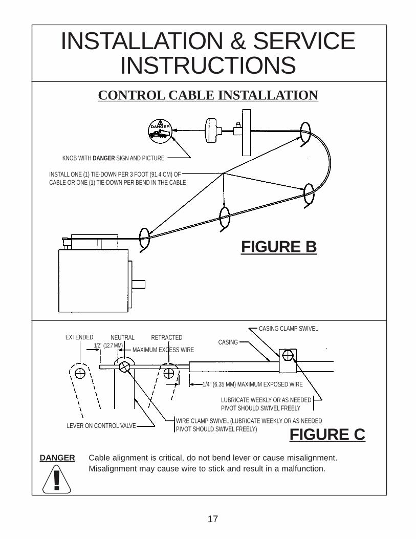
!
FIGURE B
DANGER Cable alignment is critical, do not bend lever or cause misalignment.Misalignment may cause wire to stick and result in a malfunction.
INSTALLATION & SERVICEINSTRUCTIONS
CONTROL CABLE INSTALLATION
FIGURE C
KNOB WITH DANGER SIGN AND PICTURE
INSTALL ONE (1) TIE-DOWN PER 3 FOOT (91.4 CM) OFCABLE OR ONE (1) TIE-DOWN PER BEND IN THE CABLE
CASING
CASING CLAMP SWIVELRETRACTED
MAXIMUM EXCESS WIRE
EXTENDED NEUTRAL1/2” (12.7 MM)
LEVER ON CONTROL VALVE
1/4” (6.35 MM) MAXIMUM EXPOSED WIRE
WIRE CLAMP SWIVEL (LUBRICATE WEEKLY OR AS NEEDEDPIVOT SHOULD SWIVEL FREELY)
LUBRICATE WEEKLY OR AS NEEDEDPIVOT SHOULD SWIVEL FREELY
17

!DANGER
D. Identify the model of control valve on the unit you are installing and the spacernut to be used on the cable from drawings in Figure D below.
CONTROL CABLE INSTALLATION (CONTINUED)
SPACER NUTS – (INCLUDED WITH CABLE HEAD)
FIGURE D
Use the 2342 spacer with a Williams®’ #3 valve.
#3 VALVE
#4 VALVE
#6, #7, #8 VALVE
“M” SERIES
MANUAL ELECTRIC VALVE
18
STROKE LIMITING SPACERS FOR CONTROL CABLE INSTALLATIONTwo stroke limiting spacers have been supplied with your cable head. A stroke limiting spacermust be used on the knob end of the cable head to prevent over-travel of the plunger. Withoutthe proper spacer, the plunger may over-travel causing the cable to kink and the cable willnot operate properly. Use the information below to determine which spacer to use withWilliams®’ valves. Failure to follow these instructions may result in serious injury or death.(Each spacer is supplied with a #6-32 set screw to secure the spacer to the cable head plunger.)
3/16”(4.75mm) 1-5/16”
(33.3mm)
Use the 2343 spacer with a Williams®’ #4 valve.
Use the 2342 & 2343 spacers with a Williams®’ manual electric valve.
1) Place O’ring (A) on to seat (B) 2) Slide ball (C) into slot (D) 3) Push nut (E) onto threads (F) and tighten securely.
ASSEMBLY INSTRUCTIONS FOR CABLE AND CABLE HEAD.Install Spacer Here C D F
B
A E
2342
2342
2343
2343
Use the 2343 spacer with a Williams®’ #6, #7, #8 valve.
Use the 2343 spacer with a Williams®’ M-unit.
2343
2343
Williams® p/n 2342 Williams® p/n 2343
!
!
! !
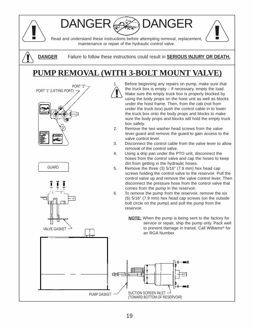
1. Before beginning any repairs on pump, make sure that the truck box is empty – if necessary, empty the load. Make sure the empty truck box is properly blocked by using the body props on the hoist unit as well as blocks under the hoist frame. Then, from the cab (not from under the truck box) push the control cable in to lower the truck box onto the body props and blocks to make sure the body props and blocks will hold the empty truck box safely.2. Remove the two washer head screws from the valve lever guard and remove the guard to gain access to the valve control lever.3. Disconnect the control cable from the valve lever to allow removal of the control valve.4. Using a drip pan under the PTO unit, disconnect the hoses from the control valve and cap the hoses to keep dirt from getting in the hydraulic hoses.5. Remove the three (3) 5/16" (7.9 mm) hex head cap screws holding the control valve to the reservoir. Pull the control valve up and remove the valve control lever. Then disconnect the pressure hose from the control valve that comes from the pump in the reservoir.6. To remove the pump from the reservoir, remove the six (6) 5/16" (7.9 mm) hex head cap screws (on the outside bolt circle on the pump) and pull the pump from the reservoir.
NOTE: When the pump is being sent to the factory forservice or repair, ship the pump only. Pack wellto prevent damage in transit. Call Williams® foran RGA Number.
DANGER DANGERRead and understand these instructions before attempting removal, replacement,
maintenance or repair of the hydraulic control valve.
DANGER Failure to follow these instructions could result in SERIOUS INJURY OR DEATH.
PUMP REMOVAL (WITH 3-BOLT MOUNT VALVE)
PORT “2”PORT “1” (LIFTING PORT)
GUARD
VALVE GASKET
PUMP GASKET SUCTION SCREEN INLET(TOWARD BOTTOM OF RESERVOIR)
19
1. Before beginning any repairs on pump, make sure that the truck box is empty – if necessary, empty the load. Make sure the empty truck box is properly blocked by using the body props on the hoist unit as well as blocks under the hoist frame. Then, from the cab (not from under the truck box) push the control cable in to lower the truck box onto the body props and blocks to make sure the body props and blocks will hold the empty truck box safely.2. Remove the two washer head screws from the valve lever guard and remove the guard to gain access to the valve control lever.3. Disconnect the control cable from the valve lever to allow removal of the control valve.4. Using a drip pan under the PTO unit, disconnect the hoses from the control valve and cap the hoses to keep dirt from getting in the hydraulic hoses.5. Remove the valve control lever. Then remove the four (4) 5/16" (7.9 mm) hex head cap screws holding the control valve to the reservoir. Pull the control valve up and disconnect the pressure hose from the control valve that comes from the pump in the reservoir.6. To remove the pump from the reservoir, remove the six (6) 5/16" (7.9 mm) hex head cap screws (on the outside bolt circle on the pump) and pull the pump from the reservoir.
NOTE: When the pump is being sent to the factory forservice or repair, ship the pump only. Pack wellto prevent damage in transit. Call Williams® foran RGA Number.
DANGER DANGERRead and understand these instructions before attempting removal, replacement,
maintenance or repair of the hydraulic control valve.
DANGER Failure to follow these instructions could result in SERIOUS INJURY OR DEATH.
PUMP REMOVAL (WITH 4-BOLT MOUNT VALVE)
!
!
! !
PORT “A”PORT “B” (LIFTING PORT)
GUARD
VALVE GASKET
PUMP GASKET
SUCTIONSCREEN INLET(TOWARD BOTTOM OF RESERVOIR)
20

QTY.REQ.
QTY.REQ.
NO. NO.PART DESCRIPTION PART DESCRIPTIONPART NO.
PART NO.
NOTE: LETTER CODE INDICATES RELIEF PRESS. SETTING AND IS LOCATED ON REAR MAIN BEARING HOUSING. NEW VALVE GASKETS ARE RECOMMENDED WHEN REPLACING PUMP. THE PUMP MODEL # AND SERIAL # ARE LOCATED ON FRONT OF PUMP.
18 1009 4 WASHER
19 1008 4 PORT STUD
20 1035 6 CAP SCREWS
22 1664 1 INTAKE PIPE
21 1059 PUMP CASTING (Not Sold Seperately)
REMAINING PUMP PARTS
25 1033 1 REAR BEARING HOUSING
24 2664 1 INTAKE SCREEN
26 1040 1 HOUSING SET SCREW & NUT
28 -- HOSE - SPECIFY RESERVOIR SIZE WHEN ORDERING
27 1060 1 RELIEF VALVE (SPECIFY PUMP MODEL,SERIAL#, PRESS. & RPM)
11 1027 1 KEY
17 1016 2 INTAKE SPRING
14 1015 4 BALL
13 1043 4 SEAT
1432 INTAKE and EXHAUST VALVE KIT
12 1006 2 PISTON and ROD ASSEMBLY
1431 PISTON and CONNECTING ROD KIT
15 1041 2 CAGE SPRING
16 2264 2 EXHAUST SPRING
10 1055 3 NYLON THRUST WASHER
6 1023 2 NEEDLE BEARING
1430 SHAFT AND BEARING KIT
1433 SEAL KIT
8 1004 2 ECCENTRICS
7 29466A 1 SPIROLOX RING
5 1002 1 SHAFT
2 1012 1 PUMP GASKET
1 1028 2 OIL SEAL
3 1030 6 ALUMINUM WASHER
9 1026 2 KEY, ECCENTRIC
2524
28
6
181516
12
2
27
22
10218
9
6
5
17
108
11
MODEL 20 PUMP PARTS LIST
18171413
19
26
203
21

NOTE: LETTER CODE INDICATES RELIEF PRESS. SETTING AND IS LOCATED ON REAR MAIN BEARING HOUSING. NEW VALVE GASKETS ARE RECOMMENDED WHEN REPLACING PUMP. THE PUMP MODEL # AND SERIAL # ARE LOCATED ON FRONT OF PUMP.
21 1054 PUMP CASTING (Not Sold Seperately)
18 1009 8 WASHER
25 1033 1 REAR BEARING HOUSING
26 1040 1 HOUSING SET SCREW & NUT
24 2664 1 INTAKE SCREEN
20 1035 6 CAP SCREWS
22 1664 1 INTAKE PIPE
19 1008 8 PORT STUD
REMAINING PUMP PARTS
27 1060 1 RELIEF VALVE (SPECIFY PUMP MODEL,SERIAL#, PRESS. & RPM)
28 -- HOSE - SPECIFY RESERVOIR SIZE WHEN ORDERING
NO.
11 1027 1 KEY
14 1015 8 BALL
1435 PISTON and CONNECTING ROD KIT
16 2264 4 EXHAUST SPRING
13 1043 8 SEAT
1436 INTAKE and EXHAUST VALVE KIT
15 1041 4 CAGE SPRING
12 1006 4 PISTON and ROD ASSEMBLY
17 1016 4 INTAKE SPRING
9 1026 4 KEY, ECCENTRIC
10 1055 3 NYLON THRUST WASHER
3 1030 6 ALUMINUM WASHER
1434 SHAFT AND BEARING KIT
1433 SEAL KIT
6 1023 2 NEEDLE BEARING
8 1004 4 ECCENTRICS
7 29466A 1 SPIROLOX RING
5 1005 1 SHAFT
2 1012 1 PUMP GASKET
1 1028 2 OIL SEAL
PART DESCRIPTIONQTY.REQ.
NO. PART NO.
PART DESCRIPTIONQTY.REQ.
PART NO.
625
28
12
15 1816
2
24
27
22
108
5
216
9
1
11
78
10
MODEL 40 PUMP PARTS LIST
1413
1726
320
18
19
22

QTY.REQ.
QTY.REQ.
PART DESCRIPTIONPART NO.
NO. PART NO.
PART DESCRIPTIONNO.
REMAINING PUMP PARTS
31,32 1087 2 DUAL RELIEF VALVE (SPECIFY PUMP MODEL, SERIAL#, PRESS. & R.P.M.)
37 1237 1 INTAKE HOUSING TUBE36 1231 1 PUMP CASTING (Not Sold Seperately)
38 1350 1 FRONT CASTING
30 1008 8 PORT STUD
1354 EXHAUST VALVE KIT25 1043 8 SEAT
27 2264 8 EXHAUST SPRING
28 1041 8 CAGE SPRING
26 1015 8 BALL
29 1009 8 WASHER
1356 PISTON KIT
18 1168 8 BALL
19 1233 8 BALL STOP
20 1234 8 SPRING
17 1235 8 PISTON
41 -- HOSE - SPECIFY RESERVOIR SIZE WHEN ORDERING
40 1035 6 MOUNTING CAP SCREW
42 1515 1 INTAKE SCREEN
39 1107 8 PUMP ASSEMBLY BOLT
1357 THRUST BEARING KIT
10 1080 1 THRUST RACE
14 1078 1 REAR ROLLER RETAINER
11 1077 1 FRONT ROLLER RETAINER
13 1232 1 WOBBLE PLATE
12 1119 32 THRUST ROLLER BEARING
16 1076 1 PISTON THRUST PLATE
15 1106 1 THRUST PLATE BEARING
9 1117 1 WOBBLE KEY
7 1027 1 SHAFT KEY
8 1118 2 SNAP RING
3 1030 6 ALUMINUM WASHER
1 1028 2 OIL SEAL
2 1012 1 PUMP GASKET
1359 SEAL KIT
1358 SHAFT AND BEARING KIT
6 1023 2 NEEDLE BEARING5 1075 1 SHAFT
4 1108 8 ALUMINUM WASHER
NOTE: LETTER CODE ON RELIEF INDICATES RELIEF PRESS. SETTING. NEW VALVE GASKETS ARE RECOMMENDED WHEN REPLACING PUMP.
1516
42
37
32
2
41
31
27
25
2826
29
30
6
20
17
36
1918
13
78
98
5
39
34
40
1011
1
12
38
6
MODEL D58 PUMP PARTS LIST
14
12
23

D58X_24.VLM REV 3/24/04
3
4
1355 CHECK VALVE KIT
31 2663 1 LOW PRESS. RELIEF SPECIFY PUMP MODEL,32 1087 1 HIGH PRESS. RELIEF SERIAL#, PRESSURE & R.P.M.)
1354 EXHAUST VALVE KIT
37 1237 1 INTAKE HOUSING TUBE
REMAINING PUMP PARTS35 1243 2 90° FITTING
34 1351 1 PILOT HOSE
22 2383 1 CAGE SPRING
25 1043 8 SEAT
24 1217 1 BALL
23 1216 1 SPRING
21 1221 1 PLUG
42 1515 1 INTAKE SCREEN
36 1238 1 PUMP CASTING (Not Sold Seperately)
38 1350 1 FRONT CASTING
33 1245 1 UNLOADING VALVE
1352 UNLOADING VALVE KIT
27 2264 8 EXHAUST SPRING
41 -- HOSE - SPECIFY RESERVOIR SIZE WHEN ORDERING
40 1035 6 MOUNTING CAP SCREW
39 1107 8 PUMP ASSEMBLY BOLT
28 1041 8 CAGE SPRING
26 1015 8 BALL
30 1008 8 PORT STUD
29 1009 8 WASHER
PART DESCRIPTION
MODEL D58X PUMP PARTS LIST(TWO STAGE PUMP)
1359 SEAL KIT
17 1235 8 PISTON
11 1077 1 FRONT ROLLER RETAINER
12 1119 32 THRUST ROLLER BEARING
14 1078 1 REAR ROLLER RETAINER
1356 PISTON KIT
18 1168 8 BALL
19 1233 8 BALL STOP
16 1076 1 PISTON THRUST PLATE
15 1106 1 THRUST PLATE BEARING
13 1232 1 WOBBLE PLATE
20 1234 8 SPRING
1 1028 2 OIL SEAL
8 1118 2 SNAP RING
7 1027 1 SHAFT KEY
10 1080 1 THRUST RACE
1358 SHAFT AND BEARING KIT
9 1117 1 WOBBLE KEY
2 1012 1 PUMP GASKET
4 1108 8 ALUMINUM WASHER
5 1075 1 SHAFT
6 1023 2 NEEDLE BEARING
3 1030 6 ALUMINUM WASHER
1357 THRUST BEARING KIT
24
NOTE: LETTER CODE ON RELIEF INDICATES RELIEF PRESS. SETTING. NEW VALVE GASKETS ARE RECOMMENDED WHEN REPLACING PUMP.
PART DESCRIPTIONQTY.REQ.
PART NO.
NO.
42
24
31
25262626
28
33
41
2
32
2927
30
2322
34
21
36
6
35
78
PART NO.
89
NO.
5
13
QTY.REQ.
15
16
1718
37
2019
17
14
1
3940
6
11
3810
24
}
QTY.REQ.
QTY.REQ.
PART NO.
PART NO.
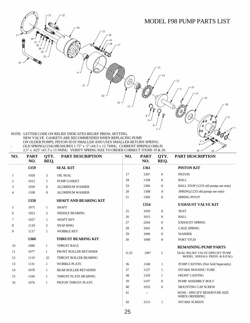
20 1368 8 SPRING(1233 old pumps see note)
19 1366 8 BALL STOP (1233 old pumps see note)
31,32 1087 2 DUAL RELIEF VALVE (SPECIFY PUMP MODEL, SERIAL#, PRESS. & R.P.M.)
27 2264 8 EXHAUST SPRING
28 1041 8 CAGE SPRING
26 1015 8 BALL
30 1008 8 PORT STUD
REMAINING PUMP PARTS
29 1009 8 WASHER
37 1237 1 INTAKE HOUSING TUBE
36 1240 1 PUMP CASTING (Not Sold Seperately)
1354 EXHAUST VALVE KIT
17 1367 8 PISTON
18 1168 8 BALL
1361 PISTON KIT
21 1369 8 SPRING PIVOT
25 1043 8 SEAT
42 1515 1 INTAKE SCREEN
41 -- HOSE - SPECIFY RESERVOIR SIZE WHEN ORDERING
40 1035 6 MOUNTING CAP SCREW
39 1107 8 PUMP ASSEMBLY BOLT
38 1350 1 FRONT CASTING
1360 THRUST BEARING KIT
12 1119 32 THRUST ROLLER BEARING
13 1131 1 WOBBLE PLATE
11 1077 1 FRONT ROLLER RETAINER
10 1080 1 THRUST RACE
16 1076 1 PISTON THRUST PLATE
15 1106 1 THRUST PLATE BEARING
14 1078 1 REAR ROLLER RETAINER
9 1117 1 WOBBLE KEY
1359 SEAL KIT
2 1012 1 PUMP GASKET
1 1028 2 OIL SEAL
3 1030 6 ALUMINUM WASHER
8 1118 2 SNAP RING
7 1027 1 SHAFT KEY
4 1108 8 ALUMINUM WASHER
5 1075 1 SHAFT
6 1023 2 NEEDLE BEARING
1358 SHAFT AND BEARING KIT
NOTE: LETTER CODE ON RELIEF INDICATES RELIEF PRESS. SETTING. NEW VALVE GASKETS ARE RECOMMENDED WHEN REPLACING PUMP.ON OLDER PUMPS, PISTON ID IS SMALLER AND USES SMALLER RETURN SPRING.
. OLD SPRING(1234) MEASURES 1.75" x .5" (44.5 x 12.7MM). CURRENT SPRING(1368) IS
. 2.5" x .625" (63.5 x 15.9MM). VERIFY SPRING SIZE TO ORDER CORRECT ITEMS 19 & 20.
NO.
37
PART DESCRIPTIONNO.
16
42
32
2
41
27
25
2826
29
30
31
6
3621
1918
20
17
PART DESCRIPTION
5
78
98
15
43
12
38
6
40
1011
1
39
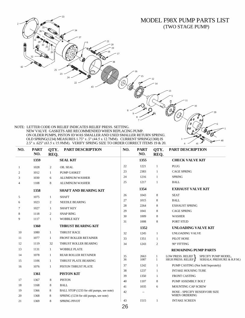
MODEL F98 PUMP PARTS LIST
13
14
12
25
26
11 1077 1 FRONT ROLLER RETAINER
19 1366 8 BALL STOP (1233 for old pumps, see note)
12 1119 32 THRUST ROLLER BEARING
17 1367 8 PISTON
16 1076 1 PISTON THRUST PLATE
15 1106 1 THRUST PLATE BEARING
13 1131 1 WOBBLE PLATE
14 1078 1 REAR ROLLER RETAINER
1361 PISTON KIT
18 1168 8 BALL
21 1369 8 SPRING PIVOT
20 1368 8 SPRING (1234 for old pumps, see note)
10 1080 1 THRUST RACE
9 1117 1 WOBBLE KEY
2 1012 1 PUMP GASKET
4 1108 8 ALUMINUM WASHER
5 1075 1 SHAFT6 1023 2 NEEDLE BEARING
3 1030 6 ALUMINUM WASHER
1360 THRUST BEARING KIT
1 1028 2 OIL SEAL
8 1118 2 SNAP RING
7 1027 1 SHAFT KEY
1358 SHAFT AND BEARING KIT
F98X_26.VLM REV 3/24/04
33 1351 1 PILOT HOSE
40 1107 8 PUMP ASSEMBLY BOLT
35 2663 1 LOW PRESS. RELIEF SPECIFY PUMP MODEL,36 1087 1 HIGH PRESS. RELIEF SERIAL#, PRESSURE & R.P.M.)
34 1243 2 90° FITTING
REMAINING PUMP PARTS
38 1237 1 INTAKE HOUSING TUBE
39 1350 1 FRONT CASTING
42 -- HOSE - SPECIFY RESERVOIR SIZE WHEN ORDERING
43 1515 1 INTAKE SCREEN
41 1035 6 MOUNTING CAP SCREW
37 1242 1 PUMP CASTING (Not Sold Seperately)
26 1043 8 SEAT
1354 EXHAUST VALVE KIT
30 1009 8 WASHER
31 1008 8 PORT STUD
27 1015 8 BALL
29 1041 8 CAGE SPRING
28 2264 8 EXHAUST SPRING
1352 UNLOADING VALVE KIT32 1245 1 UNLOADING VALVE
23 2383 1 CAGE SPRING
25 1217 1 BALL
24 1216 1 SPRING
22 1221 1 PLUG
NOTE: LETTER CODE ON RELIEF INDICATES RELIEF PRESS. SETTING. NEW VALVE GASKETS ARE RECOMMENDED WHEN REPLACING PUMP.ON OLDER PUMPS, PISTON ID WAS SMALLER AND USED SMALLER RETURN SPRING.OLD SPRING(1234) MEASURES 1.75" x .5" (44.5 x 12.7MM). CURRENT SPRING(1368) IS2.5" x .625" (63.5 x 15.9MM). VERIFY SPRING SIZE TO ORDER CORRECT ITEMS 19 & 20.
1359 SEAL KIT
17
38
QTY.REQ.
NO. PART NO.
PART DESCRIPTION
26
4225
32
3536
2
31
2729
2830
18
2423
4322
33
6 212019
37
34
1355 CHECK VALVE KIT
PART DESCRIPTIONNO. QTY.REQ.
PART NO.
8
78
9
5
13
6
403
4
1
41
11
10
39
MODEL F98X PUMP PARTS LIST(TWO STAGE PUMP)
12
14
16
15
26
}
QTY.REQ.
QTY.REQ.
PART NO.
PART NO.
31,32 1087 2 DUAL RELIEF VALVE (SPECIFY PUMP MODEL, SERIAL#, PRESS. & R.P.M.)
17 1909 8 PISTON
1354 EXHAUST VALVE KIT
36 1908 1 PUMP CASTING (Not Sold Seperately)
37 1237 1 INTAKE HOUSING TUBE
29 1009 8 WASHER
REMAINING PUMP PARTS
30 1008 8 PORT STUD
26 1015 8 BALL
28 1041 8 CAGE SPRING
27 2264 8 EXHAUST SPRING
25 1043 8 SEAT
21 1369 8 SPRING PIVOT
18 1168 8 BALL
19 1366 8 BALL STOP
20 1368 8 SPRING
2002 PISTON KIT
39 1107 8 PUMP ASSEMBLY BOLT
40 1035 6 MOUNTING CAP SCREW
41 -- HOSE - SPECIFY RESERVOIR SIZE WHEN ORDERING
42 1515 1 PUMP INTAKE SCREEN
38 1350 1 FRONT CASTING
1360 THRUST BEARING KIT
10 1080 1 THRUST RACE
11 1077 1 FRONT ROLLER RETAINER
13 1131 1 WOBBLE PLATE
12 1119 32 THRUST ROLLER BEARING
16 1076 1 PISTON THRUST PLATE
15 1106 1 THRUST PLATE BEARING
14 1078 1 REAR ROLLER RETAINER
9 1117 1 WOBBLE KEY
1359 SEAL KIT
6 1023 2 NEEDLE BEARING
5 1075 1 SHAFT
4 1108 8 ALUMINUM WASHER
7 1027 1 SHAFT KEY
8 1118 2 SNAP RING
3 1030 6 ALUMINUM WASHER
1 1028 2 OIL SEAL
2 1012 1 PUMP GASKET
1358 SHAFT AND BEARING KIT
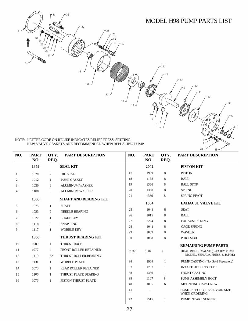
NOTE: LETTER CODE ON RELIEF INDICATES RELIEF PRESS. SETTING. NEW VALVE GASKETS ARE RECOMMENDED WHEN REPLACING PUMP.
NO.
37
PART DESCRIPTIONNO.
42
16
32
41
2
31
30
2928
25
27
26
6
1819
2136
17
20
PART DESCRIPTION
5
78
98
15
43
38
12
1
10
6
11
40 39
MODEL H98 PUMP PARTS LIST
14
13
12
27
2 23226A 2 HOUSING O-RING19 1366 8 BALL STOP4 1108 8 ALUMINUM WASHER
15 1106 1 THRUST PLATE BEARING
16 1076 1 PISTON THRUST PLATE
14 1078 1 REAR ROLLER RETAINER
13 1131 1 WOBBLE PLATE
11 1077 1 FRONT ROLLER RETAINER
10 1080 1 THRUST RACE
1360 THRUST BEARING KIT
5 1965 1 SPLINED SHAFT- 7/8" (22.2mm) - 13 tooth spline
9 1117 1 WOBBLE KEY
8 1118 2 SNAP RING
6 1023 2 NEEDLE BEARING
1982 SPLINED SHAFT AND BEARING KIT
7 NOT USED
1986 STRAIGHT SHAFT AND BEARING KIT
6 1023 2 NEEDLE BEARING
7 1027 1 SHAFT KEY
8 1118 2 SNAP RING
9 1117 1 WOBBLE KEY
5A 1966 1 STRAIGHT SHAFT - 1" (25.4mm) dia. keyed shaft
12 1119 32 THRUST ROLLER BEARING
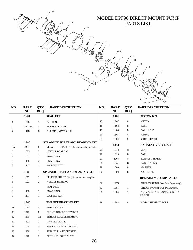
28DPF98_28.VLM REV 3/24/04
38 1960 1 FRONT CASTING - SAE-B 4 BOLT MOUNT
39 1985 8 PUMP ASSEMBLY BOLT
37 1961 1 DIRECT MOUNT PUMP HOUSING
1354 EXHAUST VALVE KIT
20 1368 8 SPRING
21 1369 8 SPRING PIVOT
25 1043 8 SEAT
27 2264 8 EXHAUST SPRING
26 1015 8 BALL
30 1008 8 PORT STUD
29 1009 8 WASHER
REMAINING PUMP PARTS
28 1041 8 CAGE SPRING
36 1978 1 PUMP CASTING (Not Sold Seperately)
1981 SEAL KIT
1 1028 2 OIL SEAL
MODEL DPF98 DIRECT MOUNT PUMP PARTS LIST
89
16
PART NO.
NO. QTY.REQ.
PART DESCRIPTION
5A
7
2927
28
30
2526
20 1918
21
17
6 2
36
37
17 1367 8 PISTON
1361 PISTON KIT
18 1168 8 BALL
4
PART DESCRIPTIONQTY.REQ.
8
NO. PART NO.
1
38
6
39
10
12
13
5
1514
12
11
2
28
2 23226A 2 HOUSING O-RING 18 1168 8 BALL
4 1108 8 ALUMINUM WASHER
29
7 1027 1 SHAFT KEY
6 1023 2 NEEDLE BEARING
1982 SPLINED SHAFT AND BEARING KIT
5A 1966 1 STRAIGHT SHAFT - 1" (25.4mm) dia. keyed shaft
7 NOT USED
8 1118 2 SNAP RING
9 1117 1 WOBBLE KEY
12 1119 32 THRUST ROLLER BEARING
13 1131 1 WOBBLE PLATE
11 1077 1 FRONT ROLLER RETAINER
14 1078 1 REAR ROLLER RETAINER
10 1080 1 THRUST RACE
1360 THRUST BEARING KIT
16 1076 1 PISTON THRUST PLATE
15 1106 1 THRUST PLATE BEARING
6 1023 2 NEEDLE BEARING
5 1965 1 SPLINED SHAFT- 7/8" (22.2mm) - 13 tooth spline
1986 STRAIGHT SHAFT AND BEARING KIT
8 1118 2 SNAP RING
9 1117 1 WOBBLE KEY
38 1960 1 FRONT CASTING - SAE-B 4 BOLT MOUNT
39 1985 8 PUMP ASSEMBLY BOLT
37 1961 1 DIRECT MOUNT PUMP HOUSIING
36 1979 1 PUMP CASTING (Not Sold Seperately)
REMAINING PUMP PARTS
29 1009 8 WASHER
26 1015 8 BALL
27 2264 8 EXHAUST SPRING
25 1043 8 SEAT
21 1369 8 SPRING PIVOT
19 1366 8 BALL STOP
20 1368 8 SPRING
1354 EXHAUST VALVE KIT
28 1041 8 CAGE SPRING
30 1008 8 PORT STUD
16
89
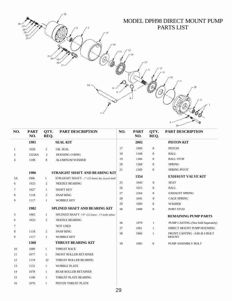
1981 SEAL KIT
1 1028 2 OIL SEAL
QTY.REQ.
NO. PART NO.
7
5A
PART DESCRIPTION
21
30
2829
20 19
27
2625
18
36
17
2
37
6
2002 PISTON KIT
4
17 1909 8 PISTON
PART DESCRIPTION
8
QTY.REQ.
PART NO.
NO.
6
38
1
39
10
MODEL DPH98 DIRECT MOUNT PUMP PARTS LIST
14
12
5 1211
13
15
2
29

30
QTY.REQ.
QTY.REQ.
PART NO.
PART NO.
1360 THRUST BEARING KIT
12 1119 32 THRUST ROLLER BEARING
11 1077 1 FRONT ROLLER RETAINER
10 1080 1 THRUST RACE
13 1131 1 WOBBLE PLATE
16 1076 1 PISTON THRUST PLATE
15 1106 1 THRUST PLATE BEARING
14 1078 1 REAR ROLLER RETAINER
8 1118 2 SNAP RING
7 1027 1 SHAFT KEY
9 1117 1 WOBBLE KEY
1359 SEAL KIT
4 1108 8 ALUMINUM WASHER
5 1075 1 SHAFT
6 1023 2 NEEDLE BEARING
1358 SHAFT AND BEARING KIT
2 1012 1 PUMP GASKET
1 1028 2 OIL SEAL
3 1030 6 ALUMINUM WASHER
28 1041 4 CAGE SPRING (SHORT)
31,32 1087 2 DUAL RELIEF VALVE (SPECIFY PUMP MODEL, SERIAL#, PRESS. & R.P.M.)
REMAINING PUMP PARTS
36 1701 1 PUMP CASTING (Not Sold Seperately)
37 1237 1 INTAKE HOUSING TUBE
42 1515 1 INTAKE SCREEN
40 1035 6 MOUNTING CAP SCREW
41 -- HOSE - SPECIFY RESERVOIR SIZE WHEN ORDERING
39 1107 8 PUMP ASSEMBLY BOLT
38 1350 1 FRONT CASTING
30 1008 4 PORT STUD (SHORT)
29 1009 8 WASHER
EXHAUST VALVE PARTS21 1369 8 SPRING PIVOT
18 1168 8 BALL
19 1366 8 BALL STOP
20 1368 8 SPRING
17 1367 8 PISTON
27 2264 4 EXHAUST SPRING (SHORT)
26 1015 8 BALL
25 1043 8 SEAT
24 1323 4 PORT STUD (LONG)
23 1321 4 CAGE SPRING (LONG)
22 1322 4 EXHAUST SPRING (LONG)
1361 PISTON KIT
NOTE: LETTER CODE ON RELIEF INDICATES RELIEF PRESS. SETTING. NEW VALVE GASKETS ARE RECOMMENDED WHEN REPLACING PUMP.
37
PART DESCRIPTIONNO.
42
16
2329
27
28
30
29
26
25
2224
3231
41
219
21
2625
36
20
6
1718
PART DESCRIPTION
5
8
7
9
8
15
NO.3940
34
6
38
1
1110
12
MODEL F944 PUMP PARTS LIST(SPLIT FLOW PUMP)
14
13
12
30

31
QTY.REQ.
QTY.REQ.
PART NO.
PART NO.
1360 THRUST BEARING KIT
12 1119 32 THRUST ROLLER BEARING
11 1077 1 FRONT ROLLER RETAINER
10 1080 1 THRUST RACE
13 1131 1 WOBBLE PLATE
16 1076 1 PISTON THRUST PLATE
15 1106 1 THRUST PLATE BEARING
14 1078 1 REAR ROLLER RETAINER
8 1118 2 SNAP RING
7 1027 1 SHAFT KEY
9 1117 1 WOBBLE KEY
1359 SEAL KIT
4 1108 8 ALUMINUM WASHER
5 1075 1 SHAFT
6 1023 2 NEEDLE BEARING
1358 SHAFT AND BEARING KIT
2 1012 1 PUMP GASKET
1 1028 2 OIL SEAL
3 1030 6 ALUMINUM WASHER
28 1041 4 CAGE SPRING (SHORT)
31,32 1087 2 DUAL RELIEF VALVE (SPECIFY PUMP MODEL, SERIAL#, PRESS. & R.P.M.)
REMAINING PUMP PARTS
36 1701 1 PUMP CASTING (Not Sold Seperately)
37 1237 1 INTAKE HOUSING TUBE
42 1515 1 INTAKE SCREEN
40 1035 6 MOUNTING CAP SCREW
41 -- HOSE - SPECIFY RESERVOIR SIZE WHEN ORDERING
39 1107 8 PUMP ASSEMBLY BOLT
38 1350 1 FRONT CASTING
30 1008 4 PORT STUD (SHORT)
29 1009 8 WASHER
EXHAUST VALVE PARTS21 1369 8 SPRING PIVOT
18 1168 8 BALL
19 1366 8 BALL STOP
20 1368 8 SPRING
17 1909 8 PISTON
27 2264 4 EXHAUST SPRING (SHORT)
26 1015 8 BALL
25 1043 8 SEAT
24 1323 4 PORT STUD (LONG)
23 1321 4 CAGE SPRING (LONG)
22 1322 4 EXHAUST SPRING (LONG)
2002 PISTON KIT
NOTE: LETTER CODE ON RELIEF INDICATES RELIEF PRESS. SETTING. NEW VALVE GASKETS ARE RECOMMENDED WHEN REPLACING PUMP.
37
PART DESCRIPTIONNO.
42
16
2329
27
28
30
29
26
25
2224
3231
41
219
21
2625
36
20
6
1718
PART DESCRIPTION
5
8
7
9
8
15
NO.3940
34
6
38
1
1110
12
MODEL H944 PUMP PARTS LIST(SPLIT FLOW PUMP)
14
13
12
31
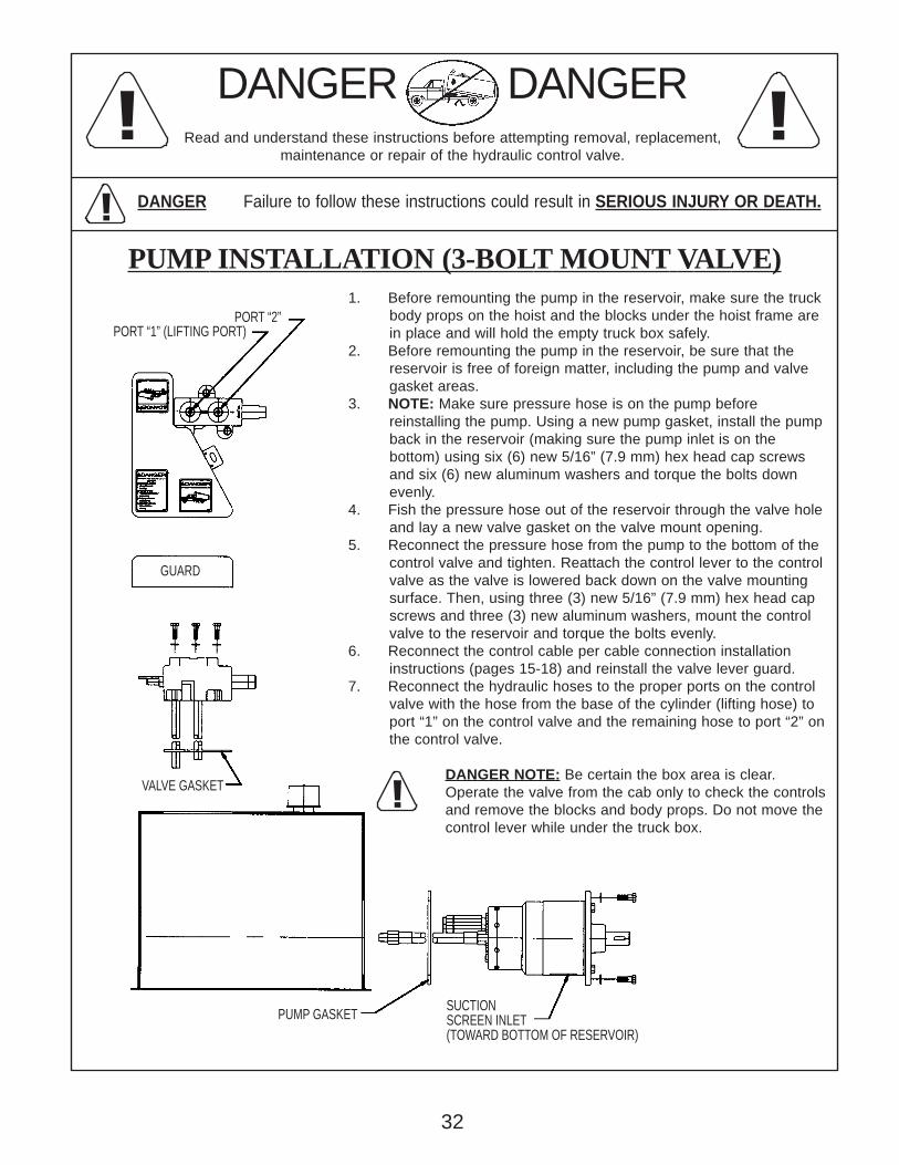
1. Before remounting the pump in the reservoir, make sure the truck body props on the hoist and the blocks under the hoist frame are in place and will hold the empty truck box safely.2. Before remounting the pump in the reservoir, be sure that the reservoir is free of foreign matter, including the pump and valve gasket areas.3. NOTE: Make sure pressure hose is on the pump before reinstalling the pump. Using a new pump gasket, install the pump back in the reservoir (making sure the pump inlet is on the bottom) using six (6) new 5/16” (7.9 mm) hex head cap screws and six (6) new aluminum washers and torque the bolts down evenly.4. Fish the pressure hose out of the reservoir through the valve hole and lay a new valve gasket on the valve mount opening.5. Reconnect the pressure hose from the pump to the bottom of the control valve and tighten. Reattach the control lever to the control valve as the valve is lowered back down on the valve mounting surface. Then, using three (3) new 5/16” (7.9 mm) hex head cap screws and three (3) new aluminum washers, mount the control valve to the reservoir and torque the bolts evenly.6. Reconnect the control cable per cable connection installation instructions (pages 15-18) and reinstall the valve lever guard.7. Reconnect the hydraulic hoses to the proper ports on the control valve with the hose from the base of the cylinder (lifting hose) to port “1” on the control valve and the remaining hose to port “2” on the control valve.
DANGER NOTE: Be certain the box area is clear.Operate the valve from the cab only to check the controlsand remove the blocks and body props. Do not move thecontrol lever while under the truck box.
DANGER DANGERRead and understand these instructions before attempting removal, replacement,
maintenance or repair of the hydraulic control valve.
DANGER Failure to follow these instructions could result in SERIOUS INJURY OR DEATH.
PUMP INSTALLATION (3-BOLT MOUNT VALVE)
!
! !
!
PORT “2”PORT “1” (LIFTING PORT)
GUARD
VALVE GASKET
PUMP GASKETSUCTIONSCREEN INLET(TOWARD BOTTOM OF RESERVOIR)
32
!
! !
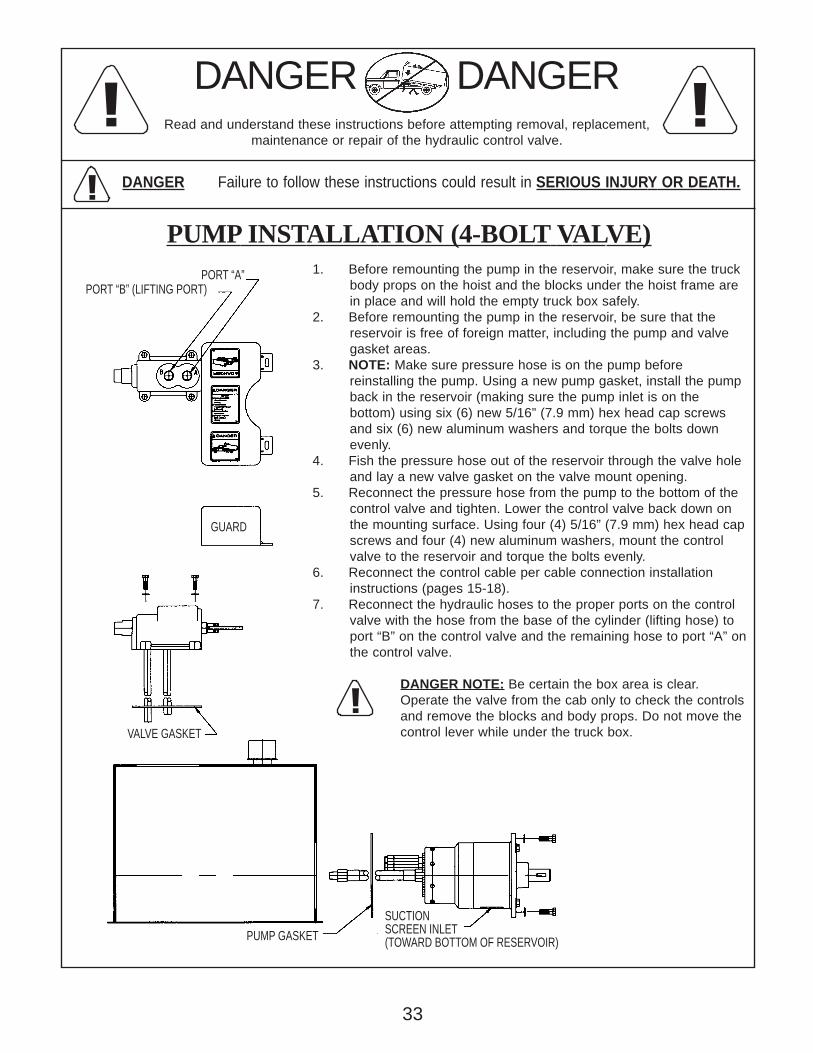
1. Before remounting the pump in the reservoir, make sure the truck body props on the hoist and the blocks under the hoist frame are in place and will hold the empty truck box safely.2. Before remounting the pump in the reservoir, be sure that the reservoir is free of foreign matter, including the pump and valve gasket areas.3. NOTE: Make sure pressure hose is on the pump before reinstalling the pump. Using a new pump gasket, install the pump back in the reservoir (making sure the pump inlet is on the bottom) using six (6) new 5/16” (7.9 mm) hex head cap screws and six (6) new aluminum washers and torque the bolts down evenly.4. Fish the pressure hose out of the reservoir through the valve hole and lay a new valve gasket on the valve mount opening.5. Reconnect the pressure hose from the pump to the bottom of the control valve and tighten. Lower the control valve back down on the mounting surface. Using four (4) 5/16” (7.9 mm) hex head cap screws and four (4) new aluminum washers, mount the control valve to the reservoir and torque the bolts evenly.6. Reconnect the control cable per cable connection installation instructions (pages 15-18).7. Reconnect the hydraulic hoses to the proper ports on the control valve with the hose from the base of the cylinder (lifting hose) to port “B” on the control valve and the remaining hose to port “A” on the control valve.
DANGER NOTE: Be certain the box area is clear.Operate the valve from the cab only to check the controlsand remove the blocks and body props. Do not move thecontrol lever while under the truck box.
DANGER DANGERRead and understand these instructions before attempting removal, replacement,
maintenance or repair of the hydraulic control valve.
DANGER Failure to follow these instructions could result in SERIOUS INJURY OR DEATH.
PUMP INSTALLATION (4-BOLT VALVE)
!
PORT “A”PORT “B” (LIFTING PORT)
GUARD
VALVE GASKET
PUMP GASKET
SUCTIONSCREEN INLET(TOWARD BOTTOM OF RESERVOIR)
33
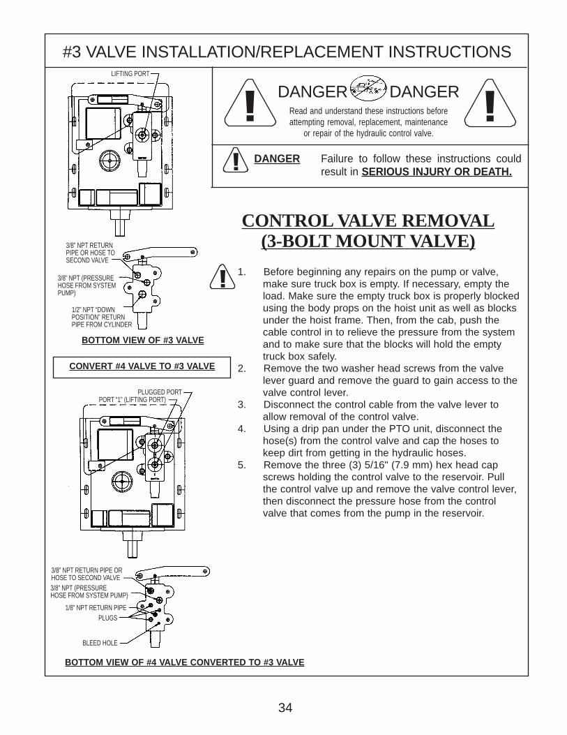
#3 VALVE INSTALLATION/REPLACEMENT INSTRUCTIONS
1. Before beginning any repairs on the pump or valve, make sure truck box is empty. If necessary, empty the load. Make sure the empty truck box is properly blocked using the body props on the hoist unit as well as blocks under the hoist frame. Then, from the cab, push the cable control in to relieve the pressure from the system and to make sure that the blocks will hold the empty truck box safely.2. Remove the two washer head screws from the valve lever guard and remove the guard to gain access to the valve control lever.3. Disconnect the control cable from the valve lever to allow removal of the control valve.4. Using a drip pan under the PTO unit, disconnect the hose(s) from the control valve and cap the hoses to keep dirt from getting in the hydraulic hoses.5. Remove the three (3) 5/16" (7.9 mm) hex head cap screws holding the control valve to the reservoir. Pull the control valve up and remove the valve control lever, then disconnect the pressure hose from the control valve that comes from the pump in the reservoir.
BOTTOM VIEW OF #3 VALVE
BOTTOM VIEW OF #4 VALVE CONVERTED TO #3 VALVE
DANGER DANGERRead and understand these instructions beforeattempting removal, replacement, maintenance
or repair of the hydraulic control valve.
DANGER Failure to follow these instructions couldresult in SERIOUS INJURY OR DEATH.
CONTROL VALVE REMOVAL(3-BOLT MOUNT VALVE)
CONVERT #4 VALVE TO #3 VALVE
!
!!
!
3/8” NPT (PRESSUREHOSE FROM SYSTEM PUMP)
BLEED HOLE
3/8” NPT RETURN PIPE ORHOSE TO SECOND VALVE
PLUGS1/8” NPT RETURN PIPE
3/8” NPT RETURNPIPE OR HOSE TOSECOND VALVE
1/2” NPT “DOWNPOSITION” RETURNPIPE FROM CYLINDER
PORT “1” (LIFTING PORT)PLUGGED PORT
LIFTING PORT
34
3/8” NPT (PRESSUREHOSE FROM SYSTEMPUMP)

#4 VALVE INSTALLATION/REPLACEMENT INSTRUCTIONS
1. Before beginning any repairs on the pump or valve, make sure truck box is empty. If necessary, empty the load. Make sure the empty truck box is properly blocked using the body props on the hoist unit as well as blocks under the hoist frame. Then, from the cab, push the cable control in to relieve the pressure from the system and to make sure that the blocks will hold the empty truck box safely.2. Remove the two washer head screws from the valve lever guard and remove the guard to gain access to the valve control lever.3. Disconnect the control cable from the valve lever to allow removal of the control valve.4. Using a drip pan under the PTO unit, disconnect the hose(s) from the control valve and cap the hoses to keep dirt from getting in the hydraulic hoses.5. Remove the three (3) 5/16" (7.9 mm) hex head cap screws holding the control valve to the reservoir. Pull the control valve up and remove the valve control lever, then disconnect the pressure hose from the control valve that comes from the pump in the reservoir.BOTTOM VIEW OF #4
CONTROL VALVE
BOTTOM VIEW OF #4C CONTROL VALVEPORT "1" PRESSURE WILL BE THE SAME AS THE PUMP PRESSURE SETTINGPORT "2" PRESSURE WILL BE AT THE "C" CARTRIDGE PRESSURE SETTING
BOTTOM VIEW OF #4R CONTROL VALVEPORT "1" & PORT "2" WILL BE AT THE SAME PRESSURE
AS THE "R" RELIEF VALVE SETTING
DANGER DANGERRead and understand these instructions beforeattempting removal, replacement, maintenance
or repair of the hydraulic control valve.
DANGER Failure to follow these instructions couldresult in SERIOUS INJURY OR DEATH.
CONTROL VALVE REMOVAL(3-BOLT MOUNT VALVE)
PRESSURE AT PORT "1" & PORT "2" WILL BE THESAME AS THE PUMP PRESSURE SETTING
!
!!
!
PORT “2”
PORT “1” (LIFTING PORT)
3/8” NPT RETURNPIPE OR HOSETO SECOND VALVE
PLUGS (4)
BLEED HOLE
3/8” NPT HOSE INLET FROM SYSTEM PUMP
“C” RELIEF CARTRIDGE INSTALLED HERE
BLEED HOLE
3/8” NPT (HOSE INLETFROM SYSTEM)PLUGS (3)
3/8” NPT RETURNPIPE OR HOSETO SECOND VALVE
“R” RELIEF CARTRIDGE INSTALLED HERE
BLEED HOLE
3/8” NPT (HOSE INLETFROM SYSTEM)PLUGS (3)
3/8” NPT RETURNPIPE OR HOSETO SECOND VALVE
35
36
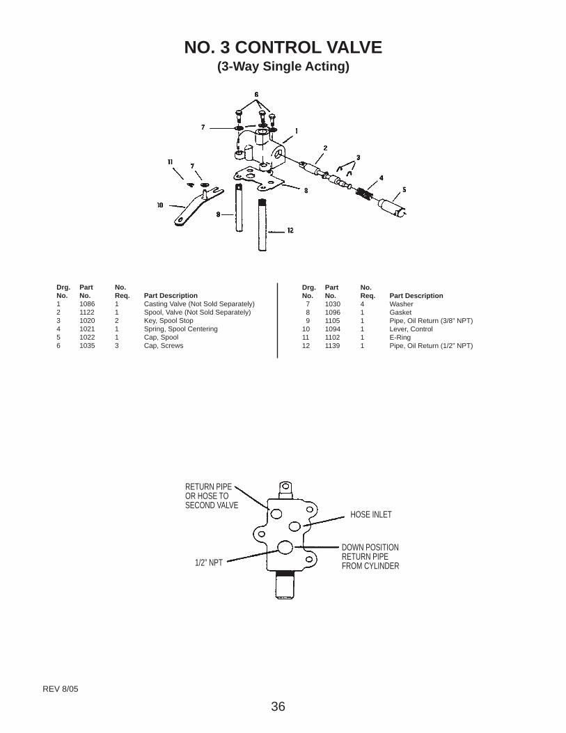
Drg. Part No.No. No. Req. Part Description1 1086 1 Casting Valve (Not Sold Separately)2 1122 1 Spool, Valve (Not Sold Separately)3 1020 2 Key, Spool Stop4 1021 1 Spring, Spool Centering5 1022 1 Cap, Spool6 1035 3 Cap, Screws
Drg. Part No.No. No. Req. Part Description 7 1030 4 Washer 8 1096 1 Gasket 9 1105 1 Pipe, Oil Return (3/8” NPT)10 1094 1 Lever, Control11 1102 1 E-Ring12 1139 1 Pipe, Oil Return (1/2” NPT)
NO. 3 CONTROL VALVE(3-Way Single Acting)
1/2” NPT
RETURN PIPEOR HOSE TOSECOND VALVE
HOSE INLET
DOWN POSITIONRETURN PIPEFROM CYLINDER
REV 8/05

37
Drg. Part No.No. No. Req. Part Description 1 1095 1 Casting (Not Sold Separately) 2 1064 1 Spool (Not Sold Separately) 3 1020 2 Key, Spool Stop 4 1021 1 Spring, Spool Centering 5 1022 1 Cap, Spool 6 1035 3 Cap, Screws 7 1030 4 Washer 8 1096 1 Gasket 9 1105 1 Pipe, Oil Return10 1094 Lever, Control11 1102 1 E-Ring12 1101 Relief Cartridge (“C” or “R”)
Specify ____________ PSI AT _____________ RPM
Pump Model No. __________ Serial No. _________
NO. 4 CONTROL VALVE(4-Way Double Acting)
Effective April 1, 1996
No. 4
No. 4RNo. 4C
HOSE INLET
BLEED HOLE
RETURN PIPE
“R” RELIEFCARTRIDGEINSTALLEDHERE
PLUGS (3)“C” RELIEFCARTRIDGEINSTALLEDHERE
RETURN PIPEOR HOSE TOSECOND VALVE
PLUGS (3)
BLEED HOLE
HOSE INLET
BLEED HOLE
RETURN PIPEOR HOSE TOSECOND VALVE
PLUGS (4)
HOSE INLET
Same Pressure at Both Ports(Pump Pressure Setting)
“C” Relief Cartridge can be Installedfor Lower Pressure at No. “2” Port Only
When used as Second Valve “R” ReliefCartridge can be Installed forLower Pressure at Both Ports
These Control Valves are identified inthe Pump Unit Model Numbers as
(-4-) (-4C-) (-4R-)The Pump Units highest workingpressure is regulated by the ReliefCartridge setting that is located on thepump.The “C” and “R” Relief Cartridges areused at a lower pressure setting togovern only parts of the system.
REV 3/04
DANGER DANGERRead and understand these instructions beforeattempting removal, replacement, maintenance
or repair of the hydraulic control valve.
DANGER Failure to follow these instructions couldresult in SERIOUS INJURY OR DEATH.
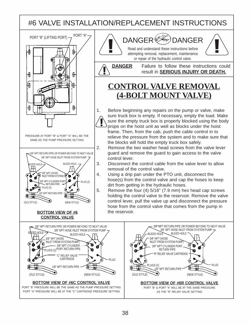
#6 VALVE INSTALLATION/REPLACEMENT INSTRUCTIONS
1. Before beginning any repairs on the pump or valve, make sure truck box is empty. If necessary, empty the load. Make sure the empty truck box is properly blocked using the body props on the hoist unit as well as blocks under the hoist frame. Then, from the cab, push the cable control in to relieve the pressure from the system and to make sure that the blocks will hold the empty truck box safely.2. Remove the two washer head screws from the valve lever guard and remove the guard to gain access to the valve control lever.3. Disconnect the control cable from the valve lever to allow removal of the control valve.4. Using a drip pan under the PTO unit, disconnect the hose(s) from the control valve and cap the hoses to keep dirt from getting in the hydraulic hoses.5. Remove the four (4) 5/16" (7.9 mm) hex head cap screws holding the control valve to the reservoir. Remove the valve control lever, pull the valve up and disconnect the pressure hose from the control valve that comes from the pump in the reservoir.
CONTROL VALVE REMOVAL(4-BOLT MOUNT VALVE)
BOTTOM VIEW OF #6CONTROL VALVE
BOTTOM VIEW OF #6C CONTROL VALVEPORT "B" PRESSURE WILL BE THE SAME AS THE PUMP PRESSURE SETTINGPORT "A" PRESSURE WILL BE AT THE "C" CARTRIDGE PRESSURE SETTING
BOTTOM VIEW OF #6R CONTROL VALVEPORT "B" & PORT "A" WILL BE AT THE SAME PRESSURE
AS THE "R" RELIEF VALVE SETTING
PRESSURE AT PORT "B" & PORT "A" WILL BE THESAME AS THE PUMP PRESSURE SETTING
!
!!
!
PORT “A”PORT “B” (LIFTING PORT)
BLEED HOLE
3/8” NPT HOSE INLET FROM SYSTEM PUMP
PLUG (2)
1/8” NPT RETURN PIPE
BLEED HOLE
(OLD STYLE) (NEW STYLE)
3/8” NPT (HOSEINLET FROM SYSTEM)
3/8” NPT CYLINDER PORTRETURN PIPE
PLUG (3)
3/8” NPT RETURN PIPE OR POWER BEYOND TO NEXT VALVE
PLUG
3/8” NPT RETURN PIPE OR POWER BEYOND TO NEXT VALVE
BLEED HOLE3/8” NPT HOSE INLET FROM SYSTEM PUMP
PLUGS (2)1/8” NPT RETURN PIPE
BLEED HOLE3/8” NPT (HOSEINLET FROM SYSTEM PUMP)
3/8” NPT CYLINDER PORTRETURN PIPE
“R” RELIEF VALVE CARTRIDGE
(OLD STYLE) (NEW STYLE)(OLD STYLE) (NEW STYLE)
1/8” NPT RETURN PIPE
BLEED HOLE3/8” NPT HOSE INLET FROM SYSTEM PUMP
BLEED HOLE3/8” NPT (HOSEINLET FROM SYSTEM PUMP)
PLUG
PLUGS (2)
3/8” NPT RETURN PIPE OR POWER BEYOND TO NEXT VALUE
38
“C” RELIEF VALVECARTRIDGE
3/8” NPT CYLINDERPORT RETURN PIPE
DANGER DANGERRead and understand these instructions beforeattempting removal, replacement, maintenance
or repair of the hydraulic control valve.
DANGER Failure to follow these instructions couldresult in SERIOUS INJURY OR DEATH.
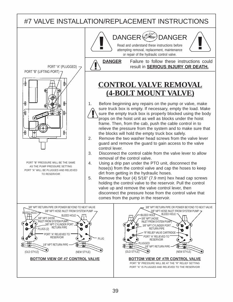
#7 VALVE INSTALLATION/REPLACEMENT INSTRUCTIONS
1. Before beginning any repairs on the pump or valve, make sure truck box is empty. If necessary, empty the load. Make sure the empty truck box is properly blocked using the body props on the hoist unit as well as blocks under the hoist frame. Then, from the cab, push the cable control in to relieve the pressure from the system and to make sure that the blocks will hold the empty truck box safely.2. Remove the two washer head screws from the valve lever guard and remove the guard to gain access to the valve control lever.3. Disconnect the control cable from the valve lever to allow removal of the control valve.4. Using a drip pan under the PTO unit, disconnect the hose(s) from the control valve and cap the hoses to keep dirt from getting in the hydraulic hoses.5. Remove the four (4) 5/16" (7.9 mm) hex head cap screws holding the control valve to the reservoir. Pull the control valve up and remove the valve control lever, then disconnect the pressure hose from the control valve that comes from the pump in the reservoir.
CONTROL VALVE REMOVAL(4-BOLT MOUNT VALVE)
BOTTOM VIEW OF #7 CONTROL VALVE BOTTOM VIEW OF #7R CONTROL VALVEPORT "B" PRESSURE WILL BE AT THE "R" RELIEF SETTINGPORT "A" IS PLUGGED AND RELIEVED TO THE RESERVOIR
PORT "B" PRESSURE WILL BE THE SAMEAS THE PUMP PRESSURE SETTING
PORT "A" WILL BE PLUGGED AND RELIEVEDTO RESERVOIR
!
!!
!
PORT “A” (PLUGGED)PORT “B” (LIFTING PORT)
3/8” NPT RETURN PIPE OR POWER BEYOND TO NEXT VALVE 3/8” NPT RETURN PIPE OR POWER BEYOND TO NEXT VALVE
BLEED HOLE3/8” NPT HOSE INLET FROM SYSTEM PUMP
PLUGGED1/8” NPT RETURN PIPE
BLEED HOLE3/8” NPT (HOSEINLET FROM SYSTEM PUMP)3/8” NPT CYLINDER PORT
RETURN PIPE
(OLD STYLE) (NEW STYLE)(OLD STYLE) (NEW STYLE)
1/8” NPT RETURN PIPE
BLEED HOLE 3/8” NPT HOSE INLET FROM SYSTEM PUMPBLEED HOLE
3/8” NPT CYLINDER PORTRETURN PIPE
3/8” NPT (HOSEINLET FROM SYSTEM PUMP)
PLUG
PLUGS (2)
39
PORT “A” RELIEVED TORESERVOIR
“R” RELIEF VALVE CARTRIDGEPORT “A” RELIEVED TO
RESERVOIR

DANGER DANGERRead and understand these instructions beforeattempting removal, replacement, maintenance
or repair of the hydraulic control valve.
DANGER Failure to follow these instructions couldresult in SERIOUS INJURY OR DEATH.
#8 VALVE INSTALLATION/REPLACEMENT INSTRUCTIONS
1. Before beginning any repairs on the pump or valve, make sure truck box is empty. If necessary, empty the load. Make sure the empty truck box is properly blocked using the body props on the hoist unit as well as blocks under the hoist frame. Then, from the cab, push the cable control in to relieve the pressure from the system and to make sure that the blocks will hold the empty truck box safely.2. Remove the two washer head screws from the valve lever guard and remove the guard to gain access to the valve control lever.3. Disconnect the control cable from the valve lever to allow removal of the control valve.4. Using a drip pan under the PTO unit, disconnect the hose(s) from the control valve and cap the hoses to keep dirt from getting in the hydraulic hoses.5. Remove the four (4) 5/16" (7.9 mm) hex head cap screws holding the control valve to the reservoir. Pull the control valve up and remove the valve control lever, then disconnect the pressure hose from the control valve that comes from the pump in the reservoir.
CONTROL VALVE REMOVAL(4-BOLT MOUNT VALVE)
BOTTOM VIEW OF #8 CONTROL VALVE BOTTOM VIEW OF #8C CONTROL VALVEPORT "B" PRESSURE WILL BE THE SAME AS THE PUMP PRESSURE SETTINGPORT "A" PRESSURE WILL BE THE SAME AS THE "C" RELIEF VALVE SETTING
PORT "B" PRESSURE WILL BE THE SAMEAS THE PUMP PRESSURE SETTING
PORT "A" PRESSURE WILL BE THE SAMEAS THE PUMP PRESSURE SETTING
!
!!
!
1/8” NPT RETURN PIPE
3/8” NPT CYLINDER PORTRETURN PIPE
PLUGS (2)
PORT “B” (LIFTING PORT)
PORT “A”
3/8” NPT RETURN PIPE OR POWER BEYOND TO NEXT VALVE3/8” NPT HOSE INLET FROM SYSTEM PUMP
BLEED HOLE
1/8” NPT RETURN PIPE
3/8” NPT PIPE WITHRECYCLE RESTRICTOR
PLUG
3/8” NPT RETURN PIPE OR POWER BEYOND TO NEXT VALVE3/8” NPT HOSE INLET FROM SYSTEM PUMP
BLEED HOLE
“C” RELIEF VALVE CARTRIDGE
40
41
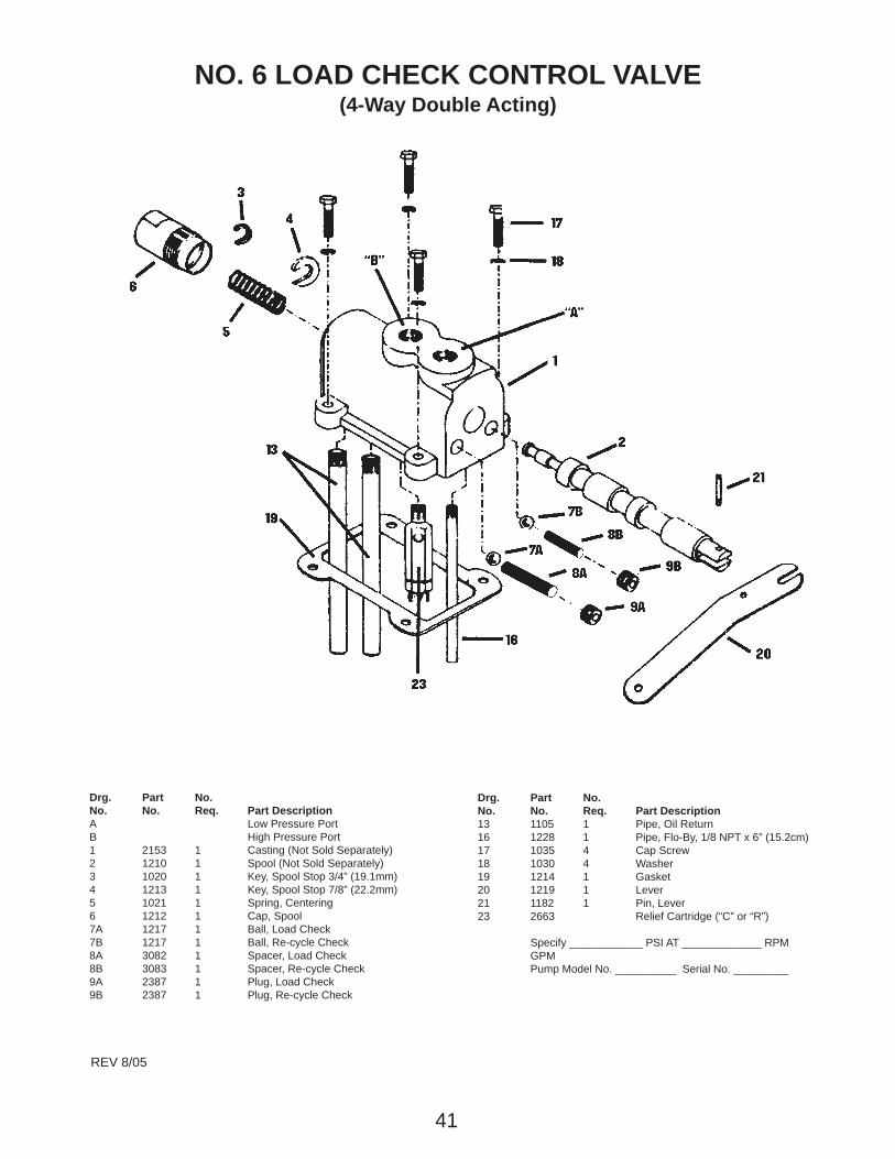
Drg. Part No.No. No. Req. Part DescriptionA Low Pressure PortB High Pressure Port1 2153 1 Casting (Not Sold Separately)2 1210 1 Spool (Not Sold Separately)3 1020 1 Key, Spool Stop 3/4” (19.1mm)4 1213 1 Key, Spool Stop 7/8” (22.2mm)5 1021 1 Spring, Centering6 1212 1 Cap, Spool7A 1217 1 Ball, Load Check7B 1217 1 Ball, Re-cycle Check8A 3082 1 Spacer, Load Check8B 3083 1 Spacer, Re-cycle Check9A 2387 1 Plug, Load Check9B 2387 1 Plug, Re-cycle Check
Drg. Part No.No. No. Req. Part Description13 1105 1 Pipe, Oil Return16 1228 1 Pipe, Flo-By, 1/8 NPT x 6” (15.2cm)17 1035 4 Cap Screw18 1030 4 Washer19 1214 1 Gasket20 1219 1 Lever21 1182 1 Pin, Lever23 2663 Relief Cartridge (“C” or “R”)
Specify ____________ PSI AT _____________ RPMGPMPump Model No. __________ Serial No. _________
REV 8/05
NO. 6 LOAD CHECK CONTROL VALVE(4-Way Double Acting)

42
Drg. Part No.No. No. Req. Part DescriptionA Low Pressure PortB High Pressure Port1 2153 1 Casting (Not Sold Separately)2 1210 1 Spool (Not Sold Separately)3 1020 1 Key, Spool Stop 3/4” (19.1mm)4 1213 1 Key, Spool Stop 7/8” (22.2mm)5 1021 1 Spring, Centering6 1212 1 Cap, Spool7A 1217 1 Ball, Load Check7B 1217 1 Ball, Re-cycle Check8A 3082 1 Spacer, Load Check8B 3083 1 Spacer, Re-cycle Check9A 2387 1 Plug, Load Check9B 2387 1 Plug, Re-cycle Check
Drg. Part No.No. No. Req. Part Description12 1221 1 Plug13 1105 Pipe, Oil Return16 1220 1 Pipe, Flo-By, 1/4 NPT x 6” (15.2cm)17 1035 4 Cap Screw18 1030 4 Washer19 1214 1 Gasket20 1219 1 Lever21 1182 1 Pin, Lever23 2663 Relief Cartridge (“R”)
Specify ____________ PSI AT _____________ RPMGPMPump Model No. __________ Serial No. _________
REV 8/05
NO. 7 LOAD CHECK CONTROL VALVE(3-Way Single Acting)

43
Drg. Part No.No. No. Req. Part DescriptionA Low Pressure PortB High Pressure Port1 2153 1 Casting (Not Sold Separately)2 1210 1 Spool (Not Sold Separately)3 1020 Key, Spool Stop 3/4” (19.1mm)4 1213 1 Key, Spool Stop 7/8” (22.2mm)5 1021 1 Spring, Centering6 1212 1 Cap, Spool7A 1217 1 Ball, Load Check7B 1217 1 Ball, Re-cycle Check8A 3082 1 Spacer, Load Check8B 3083 1 Spacer, Re-cycle Check9A 2387 Plug, Load Check9B 2387 1 Plug, Re-cycle Check
Drg. Part No.No. No. Req. Part Description13 1105 1 Pipe, Oil Return14 2308 1 Variable Restrictor Assm.15 1230 1 Pipe Nipple16 1228 1 Pipe, Flo-By, 1/8 NPT x 6” (15.2cm)17 1035 4 Cap Screw18 1030 4 Washer19 1214 1 Gasket20 1219 1 Lever21 1182 1 Pin, Lever23 2663 Relief Cartridge (“C”)
Specify ____________ PSI AT _____________ RPMGPMPump Model No. __________ Serial No. _________
REV 8/05
NO. 8 RE-CYCLE CONTROL VALVE(4-Way Double Acting - Load Check)

!
#3 VALVE INSTALLATION/REPLACEMENT INSTRUCTIONS
1. Before remounting the control valve, make sure that the truck body props on the hoist and the blocks under the hoist frame are in place to hold the empty truck box safely.2. Before remounting the control valve on the reservoir, be sure that the valve gasket area is free of foreign matter.3. Lay a new valve gasket on the valve mounting area and reconnect the pressure hose from the pump to the bottom of the control valve and tighten. Reattach the control lever to the control valve as the control valve is lowered down on the mounting surface. Then, using three (3) new 5/16" (7.9 mm) hex head cap screws and three (3) new aluminum washers, mount the control valve to the reservoir and torque the bolts evenly.4. Reconnect the control cable per cable connection instructions (pages 15-18) and reinstall the valve lever guard.5. Reconnect the hose from the base of the cylinder (lifting hose) to the only port on the #3 control valve or to port "1" on the #3 control valve which has been converted from a #4 control valve.
DANGER: Operate the control valve fromthe cab only to check the controls and liftbed to remove blocks. Do not under anycircumstances get under the hoist to movethe box.
BOTTOM VIEW OF #3 VALVE
BOTTOM VIEW OF #4 VALVE CONVERTED TO #3 VALVE
DANGER DANGERRead and understand these instructions beforeattempting removal, replacement, maintenance
or repair of the hydraulic control valve.
DANGER Failure to follow these instructions couldresult in SERIOUS INJURY OR DEATH.
CONTROL VALVE INSTALLATION(3-BOLT VALVE)
CONVERT #4 VALVE TO #3 VALVE
!!
!
!
3/8” NPT (PRESSURE HOSEFROM SYSTEM PUMP)
BLEED HOLE
3/8” NPT RETURN PIPE ORHOSE TO SECOND VALVE
PLUGS1/8” NPT RETURN PIPE
3/8” NPT (PRESSURE HOSEFROM SYSTEM PUMP)
3/8” NPT RETURN PIPE ORHOSE TO SECOND VALVE
1/2” NPT “DOWNPOSITION” RETURNPIPE FROM CYLINDER
PORT “1” (LIFTING PORT)PLUGGED PORT
LIFTING PORT
44
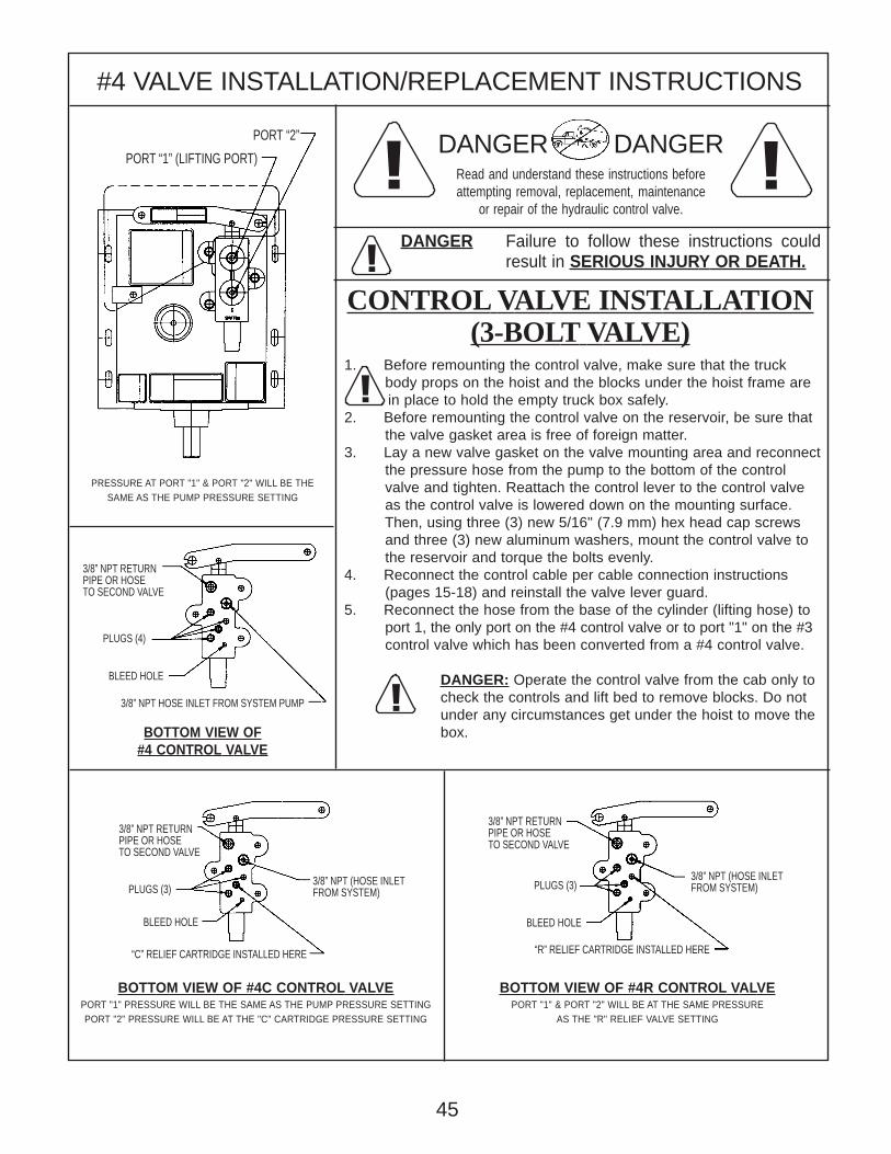
#4 VALVE INSTALLATION/REPLACEMENT INSTRUCTIONS
1. Before remounting the control valve, make sure that the truck body props on the hoist and the blocks under the hoist frame are
in place to hold the empty truck box safely.2. Before remounting the control valve on the reservoir, be sure that the valve gasket area is free of foreign matter.3. Lay a new valve gasket on the valve mounting area and reconnect the pressure hose from the pump to the bottom of the control valve and tighten. Reattach the control lever to the control valve as the control valve is lowered down on the mounting surface. Then, using three (3) new 5/16" (7.9 mm) hex head cap screws and three (3) new aluminum washers, mount the control valve to the reservoir and torque the bolts evenly.4. Reconnect the control cable per cable connection instructions (pages 15-18) and reinstall the valve lever guard.5. Reconnect the hose from the base of the cylinder (lifting hose) to port 1, the only port on the #4 control valve or to port "1" on the #3 control valve which has been converted from a #4 control valve.
DANGER: Operate the control valve from the cab only tocheck the controls and lift bed to remove blocks. Do notunder any circumstances get under the hoist to move thebox.
DANGER DANGERRead and understand these instructions beforeattempting removal, replacement, maintenance
or repair of the hydraulic control valve.
DANGER Failure to follow these instructions couldresult in SERIOUS INJURY OR DEATH.
CONTROL VALVE INSTALLATION(3-BOLT VALVE)
BOTTOM VIEW OF #4C CONTROL VALVEPORT "1" PRESSURE WILL BE THE SAME AS THE PUMP PRESSURE SETTINGPORT "2" PRESSURE WILL BE AT THE "C" CARTRIDGE PRESSURE SETTING
BOTTOM VIEW OF #4R CONTROL VALVEPORT "1" & PORT "2" WILL BE AT THE SAME PRESSURE
AS THE "R" RELIEF VALVE SETTING
BOTTOM VIEW OF#4 CONTROL VALVE
PRESSURE AT PORT "1" & PORT "2" WILL BE THESAME AS THE PUMP PRESSURE SETTING
!
!!
!
!
PORT “2”
PORT “1” (LIFTING PORT)
3/8” NPT RETURNPIPE OR HOSETO SECOND VALVE
PLUGS (4)
BLEED HOLE
3/8” NPT HOSE INLET FROM SYSTEM PUMP
“C” RELIEF CARTRIDGE INSTALLED HERE
BLEED HOLE
3/8” NPT (HOSE INLETFROM SYSTEM)PLUGS (3)
3/8” NPT RETURNPIPE OR HOSETO SECOND VALVE
“R” RELIEF CARTRIDGE INSTALLED HERE
BLEED HOLE
3/8” NPT (HOSE INLETFROM SYSTEM)PLUGS (3)
3/8” NPT RETURNPIPE OR HOSETO SECOND VALVE
45
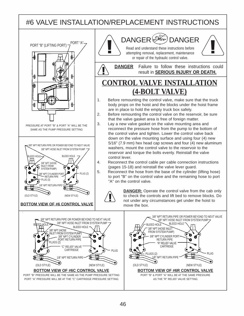
#6 VALVE INSTALLATION/REPLACEMENT INSTRUCTIONS
1. Before remounting the control valve, make sure that the truck body props on the hoist and the blocks under the hoist frame are in place to hold the empty truck box safely.2. Before remounting the control valve on the reservoir, be sure that the valve gasket area is free of foreign matter.3. Lay a new valve gasket on the valve mounting area and reconnect the pressure hose from the pump to the bottom of the control valve and tighten. Lower the control valve back down on the valve mounting surface and using four (4) new 5/16" (7.9 mm) hex head cap screws and four (4) new aluminum washers, mount the control valve to the reservoir to the reservoir and torque the bolts evenly. Reinstall the valve control lever.4. Reconnect the control cable per cable connection instructions (pages 15-18) and reinstall the valve lever guard.5. Reconnect the hose from the base of the cylinder (lifting hose) to port "B" on the control valve and the remaining hose to port "A" on the control valve.
DANGER: Operate the control valve from the cab onlyto check the controls and lift bed to remove blocks. Donot under any circumstances get under the hoist tomove the box.
DANGER DANGERRead and understand these instructions beforeattempting removal, replacement, maintenance
or repair of the hydraulic control valve.
DANGER Failure to follow these instructions couldresult in SERIOUS INJURY OR DEATH.
CONTROL VALVE INSTALLATION(4-BOLT VALVE)
BOTTOM VIEW OF #6C CONTROL VALVEPORT "B" PRESSURE WILL BE THE SAME AS THE PUMP PRESSURE SETTINGPORT "A" PRESSURE WILL BE AT THE "C" CARTRIDGE PRESSURE SETTING
BOTTOM VIEW OF #6R CONTROL VALVEPORT "B" & PORT "A" WILL BE AT THE SAME PRESSURE
AS THE "R" RELIEF VALVE SETTING
BOTTOM VIEW OF #6 CONTROL VALVE
PRESSURE AT PORT "B" & PORT "A" WILL BE THESAME AS THE PUMP PRESSURE SETTING
!
!!
!
PORT “A”PORT “B” (LIFTING PORT)
3/8” NPT RETURN PIPE OR POWER BEYOND TO NEXT VALVE
BLEED HOLE
3/8” NPT HOSE INLET FROM SYSTEM PUMP
PLUG (2)
1/8” NPT RETURN PIPE
BLEED HOLE
(OLD STYLE) (NEW STYLE)
3/8” NPT CYLINDER PORTRETURN PIPE
PLUG (3)
3/8” NPT RETURN PIPE OR POWER BEYOND TO NEXT VALVE3/8” NPT RETURN PIPE OR POWER BEYOND TO NEXT VALVE
BLEED HOLE3/8” NPT HOSE INLET FROM SYSTEM PUMP
PLUGS (2)1/8” NPT RETURN PIPE
BLEED HOLE
(OLD STYLE) (NEW STYLE)(OLD STYLE) (NEW STYLE)
1/8” NPT RETURN PIPE
BLEED HOLE 3/8” NPT HOSE INLET FROM SYSTEM PUMPBLEED HOLE
PLUG
PLUGS (2)
PLUG
46
“C” RELIEF VALVECARTRIDGE
3/8” NPT CYLINDERPORT RETURN PIPE
3/8” NPT (HOSE INLETFROM SYSTEM PUMP)
3/8” NPT CYLINDER PORTRETURN PIPE“R” RELIEF VALVE
CARTRIDGE
3/8” NPT (HOSEINLET FROMSYSTEM PUMP)
3/8” NPT (HOSEINLET FROM SYSTEM PUMP)
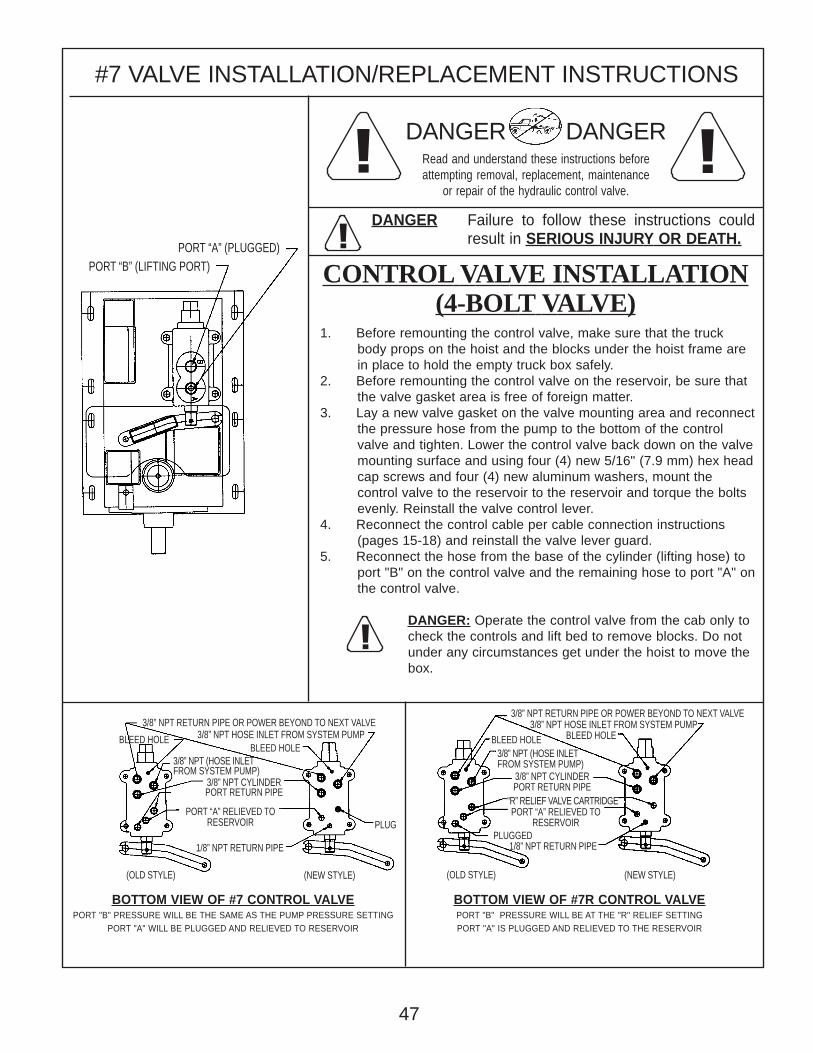
#7 VALVE INSTALLATION/REPLACEMENT INSTRUCTIONS
1. Before remounting the control valve, make sure that the truck body props on the hoist and the blocks under the hoist frame are in place to hold the empty truck box safely.2. Before remounting the control valve on the reservoir, be sure that the valve gasket area is free of foreign matter.3. Lay a new valve gasket on the valve mounting area and reconnect the pressure hose from the pump to the bottom of the control valve and tighten. Lower the control valve back down on the valve mounting surface and using four (4) new 5/16" (7.9 mm) hex head cap screws and four (4) new aluminum washers, mount the control valve to the reservoir to the reservoir and torque the bolts evenly. Reinstall the valve control lever.4. Reconnect the control cable per cable connection instructions (pages 15-18) and reinstall the valve lever guard.5. Reconnect the hose from the base of the cylinder (lifting hose) to port "B" on the control valve and the remaining hose to port "A" on the control valve.
DANGER: Operate the control valve from the cab only tocheck the controls and lift bed to remove blocks. Do notunder any circumstances get under the hoist to move thebox.
DANGER DANGERRead and understand these instructions beforeattempting removal, replacement, maintenance
or repair of the hydraulic control valve.
DANGER Failure to follow these instructions couldresult in SERIOUS INJURY OR DEATH.
CONTROL VALVE INSTALLATION(4-BOLT VALVE)
BOTTOM VIEW OF #7 CONTROL VALVEPORT "B" PRESSURE WILL BE THE SAME AS THE PUMP PRESSURE SETTING
PORT "A" WILL BE PLUGGED AND RELIEVED TO RESERVOIR
BOTTOM VIEW OF #7R CONTROL VALVEPORT "B" PRESSURE WILL BE AT THE "R" RELIEF SETTINGPORT "A" IS PLUGGED AND RELIEVED TO THE RESERVOIR
!
!!
!
PORT “A” (PLUGGED)PORT “B” (LIFTING PORT)
3/8” NPT RETURN PIPE OR POWER BEYOND TO NEXT VALVE3/8” NPT RETURN PIPE OR POWER BEYOND TO NEXT VALVE
BLEED HOLE3/8” NPT HOSE INLET FROM SYSTEM PUMP
PLUGGED1/8” NPT RETURN PIPE
BLEED HOLE3/8” NPT (HOSE INLETFROM SYSTEM PUMP)
(OLD STYLE) (NEW STYLE)(OLD STYLE) (NEW STYLE)
1/8” NPT RETURN PIPE
BLEED HOLE 3/8” NPT HOSE INLET FROM SYSTEM PUMPBLEED HOLE
PLUG
47
PORT “A” RELIEVED TORESERVOIR
3/8” NPT CYLINDERPORT RETURN PIPE
3/8” NPT CYLINDERPORT RETURN PIPE
PORT “A” RELIEVED TORESERVOIR
“R” RELIEF VALVE CARTRIDGE
3/8” NPT (HOSE INLETFROM SYSTEM PUMP)

#8 VALVE INSTALLATION/REPLACEMENT INSTRUCTIONS
1. Before remounting the control valve, make sure that the truck body props on the hoist and the blocks under the hoist frame are in place to hold the empty truck box safely.2. Before remounting the control valve on the reservoir, be sure that the valve gasket area is free of foreign matter.3. Lay a new valve gasket on the valve mounting area and reconnect the pressure hose from the pump to the bottom of the control valve and tighten. Lower the control valve back down on the valve mounting surface and using four (4) new 5/16" (7.9 mm) hex head cap screws and four (4) new aluminum washers, mount the control valve to the reservoir to the reservoir and torque the bolts evenly. Reinstall the valve control lever.4. Reconnect the control cable per cable connection instructions and reinstall the valve lever guard.5. Reconnect the hose from the base of the cylinder (lifting hose) to port "B" on the control valve and the remaining hose to port "A" on the control valve.
DANGER: Operate the control valve from the cab only tocheck the controls and lift bed to remove blocks. Do notunder any circumstances get under the hoist to move thebox.
DANGER DANGERRead and understand these instructions beforeattempting removal, replacement, maintenance
or repair of the hydraulic control valve.
DANGER Failure to follow these instructions couldresult in SERIOUS INJURY OR DEATH.
CONTROL VALVE INSTALLATION(4-BOLT VALVE)
BOTTOM VIEW OF #8 CONTROL VALVEPORT "B" PRESSURE WILL BE THE SAME AS THE PUMP PRESSURE SETTINGPORT "A" PRESSURE WILL BE AT THE "C" CARTRIDGE PRESSURE SETTING
BOTTOM VIEW OF #8C CONTROL VALVEPORT "B" PRESSURE WILL BE AT THE "R" RELIEF SETTINGPORT "A" IS PLUGGED AND RELIEVED TO THE RESERVOIR
!
!!
!
PORT “A”
PORT “B” (LIFTING PORT)
1/8” NPT RETURN PIPE
PLUGS (2)
3/8” NPT CYLINDER PORTRETURN PIPE
PLUG
1/8” NPT RETURN PIPE
“C” RELIEF VALVECARTRIDGE
3/8” NPT PIPE WITHRECYCLE RESTRICTOR
BLEEDHOLE
BLEEDHOLE
3/8” NPT RETURN PIPE OR POWER BEYOND TO NEXT VALUE 3/8” NPT RETURN PIPE OR POWER BEYOND TO NEXT VALUE3/8” NPT HOSE INLET FROM SYSTEM PUMP3/8” NPT HOSE INLET FROM SYSTEM PUMP
48
Energy Manufacturing Company, Inc. Designers & Manufacturers of Hydraulic Cylinders, Valves, Pumps, and Power Systems
204 Plastic Lane -- Monticello, IA 52310-9472 -- USA Telephone: (319) 465-3537 -- Telefax: (319) 465-5279
E-Mail Address: [email protected] Web Site: www.energymfg.com
Form 12979X (Rev. 9-09)
®
Warranty Energy Manufacturing Co., Inc., and its division, Williams Machine & Tool (hereafter collectively referred to as “Energy”), warrants its products against defects in materials and / or workmanship for a period of one (1) year from Energy’s date of manufacture. No other warranty is expressed, implied, or made. Energy’s Warranty does not extend beyond the cost of the goods sold as shown on Energy’s sales invoice. Normal in-service “wear and tear” of products and components are not covered under this Warranty. Specifically, Energy makes no warranties of merchantability of the goods or their fitness for a particular purpose. However, Energy does warrant that goods sold shall be free from defects in materials and workmanship at the time of manufacture. Energy’s Warranty does not extend to goods or materials produced by others which are incorporated into goods produced by Energy. Any claim under the Warranty contained within this document must be stated in writing to Energy within ten (10) days of the customer’s receipt of any applicable goods. Energy’s warranty liability is limited to the repair of, replacement of, credit for, or payment for, as Energy may elect, any goods determined by Energy to be defective in materials and / or workmanship. Notwithstanding any other provision contained herein, Energy will not be liable for any amount in excess of the sales price received by Energy for the goods which are determined to be defective under the provisions of this Warranty. Energy products are not covered under this, or any other warranty when used in: aerospace applications, applications involving high duty-cycle industrial use, applications involving the lifting of people, or any other application that may place persons in dangerous positions during operation. Any exceptions to these exclusions must be specifically agreed-to in writing by Energy per the terms and conditions of this document. Critical customer functions require review and special application sign-off by Energy’s product engineering group in writing in order for this Warranty to be valid and in force. Energy shall not be responsible for unacceptable conditions, operation, or performance that results from Energy products being applied without specific written application review and approval by Energy. The purchaser of any Energy product is responsible for the testing of such product for all matters concerned with its use, including but not limited to: safety testing, endurance testing and performance testing. The purchaser is further responsible for determining if the product is suitable for the purchaser's particular use or application. Energy warrants that the title to all goods sold shall be free from any security interest, other lien, or encumbrance, and that the transfer of all goods shall be rightful. Energy further warrants that goods which are shown in Energy’s price list, and which are not modified in any manner at the request of customer, shall not be subject to a claim by third parties by way of infringement. The Warranty set forth herein is the exclusive warranty for all products produced by Energy, and there is no other warranty, expressed or implied. Energy hereby expressly disclaims any and all other warranties, including implied warranties of merchantability and fitness for a particular purpose and non-infringement. Warranty coverage is dependant on buyer complying with the then-current warranty procedures and failure to comply will void this warranty in its entirety. IN NO EVENT SHALL ENERGY HAVE ANY LIABILITY OR RESPONSIBILITY TO BUYER OR ANY OTHER PERSON OR ENTITY FOR ANY CONSEQUENTIAL, INDIRECT, SPECIAL, PUNITIVE OR INCIDENTAL DAMAGES OR LOST PROFITS, WHETHER FORESEEABLE OR UNFORESEEABLE, BASED ON CLAIMS OF BUYER OR ITS CUSTOMERS (INCLUDING, BUT NOT LIMITED TO, CLAIMS FOR LOSS OF GOODWILL, PROFITS, USE OF MONEY OR USE OF GOODS, INTERRUPTION IN USE OR AVAILABILITY OF GOODS, STOPPAGE OF OTHER WORK OR IMPAIRMENT OF OTHER ASSETS, OR CLEAN-UP EXPENSES OR RELATED COSTS ASSOCIATED WITH ANY HYDRAULIC OIL SPILLS OR LEAKS OR ANY OTHER DAMAGE OR CLAIM RELATED TO THE USE OF PRODUCTS), ARISING OUT OF ANY BREACH OR FAILURE OF ANY EXPRESS WARRANTY, BREACH OF CONTRACT, MISREPRESENTATION, NEGLIGENCE, PRODUCT LIABILITY, STRICT LIABILITY IN TORT OR OTHERWISE, INCLUDING ANY LATENT OR PATENT DEFECTS, EXCEPT ONLY IN THE CASE OF DEATH OR PERSONAL INJURY WHERE AND TO THE EXTENT THAT APPLICABLE LAW REQUIRES SUCH LIABILITY. IN NO EVENT WILL THE AGGREGATE LIABILITY INCURRED BY ENERGY IN ANY ACTION OR PROCEEDING, EXCEED THE TOTAL AMOUNT ACTUALLY PAID TO ENERGY BY BUYER FOR THE PURCHASE OF THE GOOD(S) THAT ACTUALLY CAUSED THE DAMAGE OR LOSS. IN ADDITION, IN NO EVENT SHALL ENERGY BE LIABLE TO BUYER FOR ANY LOSSES, DAMAGES, CLAIMS, COSTS OR EXPENSES, INCLUDING ATTORNEYS’ FEES, ARISING FROM OR RELATED TO ANY LEAK OR SPILL OF HYDRAULIC FLUID OR ANY HAZARDOUS MATERIAL (AS DEFINED UNDER ANY APPLICABLE FEDERAL, STATE OR LOCAL STATUTE, REGULATION OR THE LIKE) OR THE FAILURE OF BUYER TO PROPERLY DISPOSE OF HYDRAULIC FLUID OR ANY HAZARDOUS MATERIAL. BUYER ALSO AGREES TO DEFEND AND HOLD ENERGY AND ITS EMPLOYEES, REPRESENTATIVES, AGENTS, SUCCESSORS OR ASSIGNS HARMLESS FROM ANY AND ALL LOSSES, DAMAGES, CLAIMS, COSTS OR EXPENSES, INCLUDING ATTORNEYS’ FEES, ARISING FROM OR RELATED TO ANY ENVIRONMENTAL OR HAZARDOUS MATERIAL CLAIMS. Written authorization for the return of products for warranty consideration must be obtained from Energy prior to return shipment. Any alleged nonconforming products shall be shipped to Energy, freight prepaid by the Shipper, along with a complete explanation of the alleged problem. Potential warranty items must be returned to Energy within thirty (30) days of receiving written authorization for return. If the products returned are not found to be nonconforming, the owner / shipper shall be responsible for and shall pay to Energy normal inspection and / or repair, and / or shipping charges. No Warranty contained herein shall be enlarged or modified, nor shall any additional warranties be applicable, unless contained in writing and signed by a corporate officer of Energy at its headquarters in Monticello, Iowa, USA.
MACHINE & TOOL
WILLIAMS® MACHINE & TOOL204 Plastic Lane • Monticello, IA 52310-9472 USAPhone: (319) 465-3537 • Fax: (319) 465-5279Web Site: www.williamsmachineandtool.comE-mail: [email protected]
Williams® is a registered trademark of Energy® Manufacturing Company, Inc. ©2009 Williams® Machine & Tool
Williams® is a member of:• NFPA (National Fluid Power Association)
• NTEA
A brand of quality productsdesigned and produced by Energy®Manufacturing – choose fromthe following expanded range ofcomponents, systems, and technologyto meet and exceed your everchanginghydraulic design needs...
ELECTRIC POWER UNITSDC (12 Volt & 24 Volt)
• Cast Stack Design (Piston & Gear)• Aluminum Design (Gear)• Bi-Rotational (Gear)• Compact (Gear)• External EPU (Gear)
AC (120 Volt & 240 Volt)
DIRECT MOUNT PUMPSPiston PumpsGear Pumps
• 900 Series• 1500 Series• Bi-Rotational Series
VALVE OPTIONS• Manual Single and Double-Acting• DO3 Single and Double-Acting• Exclusive Recycle Valve
in Manual and DO3 Versions
VALVE / TANK• “M” Series• “W” Series
REMOTE DIRECTIONALCONTROL VALVES
• 1000/2000 Series• Cartridge Stack Series
CONTROLS• Manual Cable• Electric Valve w/Toggle• Bonnet Style• Air Shift
GASOLINE POWEREDHYDRAULIC UNIT
• Light Duty• Heavy Duty
ACCESSORIES• Breather Caps• Parts
AN EXPANDED RANGE OF HYDRAULIC COMPONENTS, SYSTEMS, & TECHNOLOGYAN EXPANDED RANGE OF HYDRAULIC COMPONENTS, SYSTEMS, & TECHNOLOGYAN EXPANDED RANGE OF HYDRAULIC COMPONENTS, SYSTEMS, & TECHNOLOGYAN EXPANDED RANGE OF HYDRAULIC COMPONENTS, SYSTEMS, & TECHNOLOGYAN EXPANDED RANGE OF HYDRAULIC COMPONENTS, SYSTEMS, & TECHNOLOGY