notice of advertisement for bids furnishing...
TRANSCRIPT

January 2018 Shermco
NOTICE OF ADVERTISEMENT FOR BIDS
Furnishing and Delivery of 15kV Sheltered Aisle Switchgear For Wilton Light and Power
Wilton, Iowa, 52778
Notice is hereby given that proposals for furnishing and delivery of a 15kV, Outdoor Sheltered Aisle switchgear line-up in conformance with the attached specifications will be reviewed and acted upon at a Utility Board Meeting on January 15, 2018. Quotations will be received by Mr. Pete Smith, general manager of Wilton Municipal Light and Power (WLP), until 2:00 p.m., Thursday, January 11, at the WLP office located at 220 West Third Street, Wilton, Iowa 52778. Award will be executed by Purchase Agreement prepared by WLP and sent to the selected vendor. BID ITEM Furnish, deliver and unload F.O.B. 1500 West Division Street, Wilton, Iowa, new 15kV, Outdoor Sheltered Aisle Switchgear in accordance with the attached specifications. Bids shall be provided for that purpose and according to the Bidding Requirements prepared by Shermco Industries, dated December, 2017. The bid form shall be shall be submitted on paper to the Owner and the technical proposal submitted electronically to the Owner and Engineer. Submittals must contain the information required by these instructions to be considered complete. The Bidding Documents may be obtained at the following location: ENGINEER: David Charles Shermco 796 11th Street Marion Iowa 50302 (319) 377-3377 Contact: [email protected] Submit Bids to OWNER: Mr. Pete Smith Wilton Light and Power 220 West Third Street Wilton, Iowa, 52778

January 2018 Shermco
INSTRUCTIONS TO BIDDERS: 1. Bid Form shall be directed to Mr. Pete Smith, securely sealed and endorsed upon the outside wrapper, “BID FOR FURNISHING AND DELIVERING 15KV OUTDOOR SHELTERED ASILE SWITCHGEAR FOR WILTON LIGHT AND POWER” at 220 West Third Street, Wilton, Iowa 52778. Bids dropped off at the WLP Office will be considered if they are in the possession of Mr. Smith at the close of the bidding period. Technical submittal data may be submitted electronically any time prior to the close of bids. 2. Prices shall remain valid for a period of ninety (90) days after January 15, 2018. 3. To be considered, Bids shall be submitted on the Bid Proposal Form provided. The form may be reconstituted if the contents are duplicated. Failure to complete or submit the proposal form and provide the required technical submittals may result in rejection of proposal. 4. Payment will be made to the Vendor in an amount of ninety-five percent (95%) of the Proposal value, upon delivery, assembly, and testing of the Switchgear at the Owner’s site. The balance of the amount due the successful bidder will be made within 30 days following the successful energization of the Switchgear by the Owner, subject to the conditions and in accordance with the provisions of Chapters 384 and 573 of the Code of Iowa, no later than 180 days following delivery to site. 5. All bids shall indicate the Iowa sales tax as a separate line item determined from the base bid amount. 6. The Owner reserves the right to reject any and all Bids, to waive irregularities and informalities therein and to award the purchase in the best interests of the Utility. 7. Exceptions to the specifications are not acceptable. Written questions regarding the specifications may be directed to Mr. David Charles, [email protected] by e-mail at the address provided in the contact information. Please do not contact Mr. Wilson or any Owner representatives with questions regarding the specifications. 8. Delivery and energization of the switchgear are scheduled for July 2018.

BID FORM
December 11, 2017 P-1
PROPOSAL
Furnishing and Delivery of 15kV Sheltered Aisle Switchgear For Wilton Municipal Light and Power
Wilton, Iowa 52778
The undersigned agrees to perform the work as specified for the prices as stated: VENDOR NAME: _______________________________________ VENDOR ADDRESS: _______________________________________ VENDOR PHONE: _______________________________________ VENDOR E-MAIL: _______________________________________ VENDOR CONTACT: _______________________________________ NAME (TYPED OR PRINTED): _________________________________ TITLE: _________________________________ BY: _________________________________ (Individual’s signature) BASE BID LUMP SUM BID PRICE: _____________________________________________Dollars (______________) (words) (figures) Alternate: None ADD $_____________ Vendor discount for early payment: DEDUCT $_____________ NAME (TYPED OR PRINTED): _________________________________ TITLE: _________________________________ BY: _________________________________ (Individual’s signature)

BID FORM
December 11, 2017 P-2
GENERAL: Circuit Breaker Manufacturer _____________________________________ Switchgear Assembly Location _____________________________________ Delivery after receipt of order ______________________________(weeks) Drawings to be issued ARO Outline Drawings ______________________________(weeks) Electrical Drawings ______________________________(weeks) Switchgear Information Approximate Weight _______________________________ Approximate Length _______________________________ Approximate Weight _______________________________ Approximate Height _______________________________ AS PART OF THIS PROPOSAL, THE FOLLOWING ITEMS ARE TO BE SUBMITTED TO OWNER AND ENGINEER AS PDF FILES VIA EMAIL: Approximate Outline Drawing Bill of Materials Description of Painting Process General Descriptive Literature Clarifications
MEDIUM VOLTAGE SWITCHGEAR SECTION 262440
262440 - 1 12/19/2017
PART 1— GENERAL
1.01 Summary
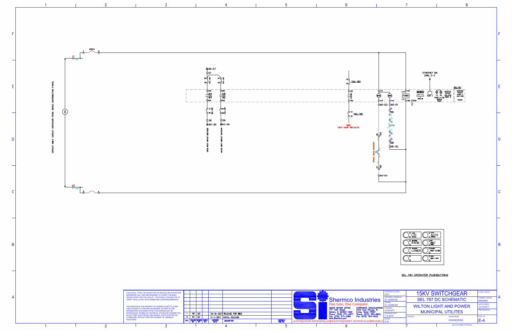
A. This specification covers the design and functional requirements for 15 kV medium voltage outdoor sheltered aisle metal-clad switchgear with vacuum circuit breakers. The switchgear includes protective equipment. A one-line diagram is provided show-ing general requirements and arrangement of the switchgear. A representation of the Wilton, Iowa Electric Distribution System is provided for reference.
1.02 Submittals
A. The following information shall be submitted with the Bid:
1) Preliminary outline drawings of the switchgear with approximate dimensions of the complete line-up.
2) Production Schedule keyed to receipt of purchase order
3) Proposed Bill of Materials
4) List of any exceptions or substitutions to the specifications
B. The following information shall be submitted to the Engineer for approval:
1) Master drawing index
2) Front view and plan view of the assembly
3) AC Three-line diagrams for each circuit breaker
4) DC Schematic diagram for each circuit breaker
5) Nameplate schedule
6) Component list with equipment model numbers.
7) Conduit space locations within the assembly
8) Assembly ratings including
a. Short-circuit rating
b. Voltage
c. Continuous current rating
9) Major component ratings including

MEDIUM VOLTAGE SWITCHGEAR SECTION 262440
262440 - 2 12/19/2017
a. Voltage
b. Continuous current rating
c. Interrupting ratings
10) Cable terminal sizes
11) Product data sheets
12) SEL Device Part Numbers
C. Where applicable, the following additional information shall be submitted to the Engi-neer
1) Busway connection
2) Composite front view and plan view of close-coupled assemblies
3) Key interlock scheme drawing and sequence of operations
4) Mimic bus size and color
1.03 Submittals – For Construction
A. Two paper copies and one electronic copy of the following information shall be sub-mitted for record purposes:
1) Final as-built drawings and information for items listed in paragraph 1.06
2) Wiring diagrams
3) Certified production test reports
4) Installation, commissioning, and start-up instructions
B. The final (as-built) drawings shall include the same drawings as the construction drawings and shall incorporate all changes made during the manufacturing and in-stallation process. Manufacturer shall provide two printed copies and electronic cop-ies in both PDF and AutoCAD formats.
C. Product Data: Include features, characteristics, and ratings of individual circuit breakers and other components. Also, provide copies of each protective and control device manual with the same information in electronic format.
1.04 Quality Assurance
A. For the equipment specified herein shall be designed, manufactured, and tested in accordance with the latest applicable standards of NEMA SG-4 and SG-5, and ANSI/IEEE C37.09, C37.12, C37.20.2 and C37.20.7.
MEDIUM VOLTAGE SWITCHGEAR SECTION 262440
262440 - 3 12/19/2017
B. The manufacturer of this equipment shall have produced similar electrical equipment for a minimum period of five (5) years. When requested by the Engineer, an ac-ceptable list of installations with similar equipment shall be provided demonstrating compliance with this requirement
1.05 Delivery Storage and Handling
A. Equipment shall be handled and stored in accordance with manufacturer’s instruc-tions. Four (4) copies of these instructions shall be included with the equipment at time of shipment.
B. Deliver products in factory labeled packages FOB job site, 1500 West Division Street, Wilton Municipal Light and Power, Wilton, Iowa 52778. Products should be delivered in the morning, during Tuesday-Thursday of the week of the delivery.
C. The power circuit breakers shall be individually tagged with its proper unit number and the equipment number of the assembly to which it belongs. Circuit breakers should not be shipped inside the switchgear lineup to avoid damage.
D. Relays shall be shipped installed in the stationary structures and shall be securely blocked and braced to prevent damage during shipment if required.
E. Each "shipping section" of stationary structures shall be provided with a permanently attached, readily visible identification tag bearing the equipment number of the as-sembly of which it is a part.
F. If shipped in sections the wiring between the units will be terminated on terminal blocks on each side of the shipping split. Jumpers shall be provided and marked for convenient connection in the field. These connections should be a “plug and play” type connection.
G. All accessory items will be shipped with the switchgear. Boxes and crates containing accessories will be clearly marked with the contents.
H. Protect from potential damage from weather and construction operations. Store so condensation will not form on or in switchgear and if necessary, apply temporary heat where required to obtain suitable service conditions.
1.06 Operational and Maintenance Manuals
A. Two (2) hard copies and one electronic copy of equipment operation and mainte-nance manuals shall be provided with each assembly shipped, and shall include in-struction leaflets and instruction bulletins for the complete assembly and each major component
1.07 References
A. The switchgear shall comply with requirements of latest revisions of applicable indus-try standards, specifically including the following:
1. ANSI/IEEE C37.04 – Standard Rating Structure for AC HV Circuit Breakers
MEDIUM VOLTAGE SWITCHGEAR SECTION 262440
262440 - 4 12/19/2017
2. ANSI/IEEE C37.06 Preferred Ratings for AC HV Circuit Breakers
3. ANSI/IEEE C37.09 Standard Test Procedure for AC HV Circuit Breakers
4. ANSI/IEEE C37.010 Application Guideline for AC HV Circuit Breakers
5. ANSI/IEEE C37.011 Application Guide for TRV for AC HV Circuit Breakers
6. ANSI/IEEE C37.012 Application Guide for Capacitance Switching
7. ANSI/IEEE C37.11 Requirements for Electrical Control
8. ANSI/IEEE C37.20.2 Standard for Metal-Clad and Station-Type Cubicle Switchgear
9. ANSI/IEEE C37.20.4 - Standard for Indoor AC Medium Voltage Switches used in Metal-Enclosed Switchgear
10. ANSI/IEEE C37.55 Conformance Testing Procedure of Metal-Clad Switch-gear
11. ANSI/IEEE C57.10 Requirements for Instrument Transformers
12. ANSI/IEEE C57.13 Requirements for Instrument Transformers
13. ANSI/IEEE 47 Guide for Surge Withstand Capability Tests
14. NEMA CC1 Electrical Power Connectors
15. NEMA SG-4 Standards for Power Circuit Breakers
16. NEMA SG-5 Power Switchgear Assemblies
17. NEC/NFPA 70 2006 Edition (applicable portions)
1.08 Regional Requirements
The switchgear enclosure shall meet the requirements of the State Building Code Chap-ter 103A which requires plan reviews and inspection (103A.10A) of the enclosure or pre-sent written documentation from the commissioner or authorized representative that the switchgear enclosure is exempt from the requirements of the Code.
1.09 Warranty
A. Seller shall warrant to the Buyer that complete switchgear and all associated compo-nents included in original purchase is free of defect in workmanship and materials.
B. Warranty shall extend for three (3) years from the date of arrival at destination from factory and covers any defects and malfunctions of the originally supplied switch-gear.
C. During first year of service, warranty shall cover any freight by common carrier in full.

MEDIUM VOLTAGE SWITCHGEAR SECTION 262440
262440 - 5 12/19/2017
PART 2— PRODUCTS
2.01 Manufacturers
A. AZZ – Central Electric
B. Eaton - Pedersen Power Products
C. EP2 – Electrical Power Products
2.02 General Design Requirements
A. The switchgear shall have a voltage rating of 15 kV with generally One (1) main cir-cuit breaker, and three (3) feeder breakers. The main breaker and feeder breaker shall be single cubicle construction. Switchgear shall have indoor frame size of 36” wide x 95” high x 95” deep. The switchgear shall meet NEMA 3R Outdoor construc-tion requirements. The switchgear will be used in a 12,470V, 3-phase, wye ground-ed, 60 Hz system. The switchgear shall be composed of factory assembled metal clad cubicles. The circuit breakers shall be designed with vacuum interrupter tech-nology.
B. 48 VDC control power shall be furnished with the switchgear from control power bat-teries installed in the switchgear. The system consists of rack mounted batteries with a 100 amp-hour rating and a 10 amp battery charger.
C. The batteries and battery charger will be connected to by circuit breakers to the DC panel furnished by the switchgear manufacturer. Control Power shall be provided to each circuit breaker individually from a 30 Amp Breaker in the DC Panel. The control power connection point and required wire size shall be indicated on the drawings. Control power for each breaker cubicle shall be individually fused for closing, trip-ping, and relay power.
D. The successful bidder shall be provided typical AC and DC schematic drawings for the main breaker and feeder breakers at the time of award to be used for shop draw-ing development. The drawings will show wiring requirements for inputs and outputs required for the various protective and control devices. For the purposes of bidding, the vendor should assume all inputs and outputs shall be wired out to terminal strips for customer connection. The actual device wiring requirements will be determined during the shop drawing approval process. Only select spare inputs and outputs shall be wired out to terminal strips.
2.03 Ratings
A. Rated Maximum Voltage 15 kV
B. Operating Voltage 12,470 kV
C. Rated Basic Impulse Level 95 kV
D. Main Bus Continuous Rating 1200A

MEDIUM VOLTAGE SWITCHGEAR SECTION 262440
262440 - 6 12/19/2017
E. Control bus DC Voltage (Nom.) 48VDC
F. Circuit Breaker Interrupting Rating 25 kA
G. Breaker Interrupting Time 5 cycles (or less)
H. Temperature rise of the switchgear will be in accordance with the latest revision of ANSI C.37.20 for metal clad switchgear.
I. The equipment shall be completely factory assembled and tested prior to shipment.
2.04 Construction
A. Basic Construction
1. The outdoor enclosure shall be fabricated from 11-gauge steel and be fully as-sembled at the factory on a structural steel base. The enclosure shall be rodent-proof and weatherproof. All bolts utilized in the construction of the enclosure shall be minimum 3/8”, grade 5. Any welded studs shall be minimum 3/8”, grade 2, nick-el-plated. Roof panel hardware shall include neoprene bonded stainless steel washers installed on each side to weatherproof the bolt threads and bolt holes. All exposed external hardware shall be stainless steel. The design and construc-tion of the enclosure shall minimize the use of gaskets and prevent the entrance of moisture and dust. Gaskets shall be limited to doors, power and control cable entrance cover plates and between the base and walls. All roof and wall seams shall be caulked with an extended life silicone sealant. Any external panels shall be attached using welded studs in order to minimize the use of through bolts.
2. The base shall be constructed of welded structural members that provide a rigid, square and level foundation for the enclosure. The base shall be capable of with-standing stresses resulting from skidding, rolling, or lifting of a completed shipping section with all equipment installed. The base shall be designed such that it can be installed on a foundation with the rear of the switchgear overhanging a flat pad or on piers. Cutouts with aluminum cover plates shall be provided in the floor at locations where conduits enter the enclosure. Crossbeams and channels shall be positioned to ensure complete access while maintaining structural integrity. Lifting provisions shall be permanently welded to the base at all four corners of each shipping split.
3. A two inch space shall be provided between the switchgear and end walls to pre-vent condensation from forming on the interior switchgear walls.
B. Roof Insulation and Venting
1. Spray-on thermal insulation or thermal insulating panels shall be applied to the entire roof to prevent condensation from forming on the interior roof surface. Ven-tilation openings shall be provided in the roof that to allow heat generated by cur-rent carrying components to be safely vented to the outside. Each opening shall be covered by a rain hood to prevent entrance of wind blown rain or snow from entering. A cleanable and re-usable filter shall be installed in the vent hood along with a screen to prevent insects from building nests that may inhibit the flow of air.

MEDIUM VOLTAGE SWITCHGEAR SECTION 262440
262440 - 7 12/19/2017
C. Front and Rear Doors
1. Each switchgear cubicle shall have a hinged, full height, front and rear door. The front doors shall provide access to the front of the switchgear cubicle. The rear doors shall provide weatherproof access to the power cable compartment. The rear doors shall be weather tight and include a three-point latching mechanism and external stainless steel handle with provisions for padlocking. A compressible automotive type gasket shall be provided on the top, bottom and sides of the door to prevent entrance of moisture and air borne contaminants. Front doors provided with internal hardware shall consist of a nylon roller at all three interface points. When closed, the door shall be flush with the enclosure. A door holding mecha-nism shall be installed at the bottom of each door that automatically engages when the door is fully open and is held in position by a spring and can be disen-gaged using downward force. The operating rod shall be strong and not deform under any attempt to close the door without release.
2. Rear doors shall have ventilation openings at the top and bottom. Each opening shall be provided with a cleanable and reusable aluminum filter that is accessible without opening the door. Protective hoods with insect screens shall be installed over vent openings to prevent entrance of rain or snow during turbulent wind con-ditions.
D. Floor
1. All open floor areas shall be fabricated from 7 gauge steel plate. The floor plates shall be welded to structural steel angle supports that are spaced at 12” centers over the entire floor area. The floor shall be coated with a skid resistant epoxy fin-ish that is fully cured prior to assembly. All open floor areas shall to be protected by masonite sheets during manufacturing. The masonite sheets shall be left in place to protect the floor during field installation and site testing. The sheets may be discarded when the equipment is placed into full time service.
E. The switchgear shall be factory assembled and tested, and comply with applicable industry standards. It shall be a coordinated design so that shipping groups are easi-ly connected together at the site into a continuous line-up. Necessary connecting materials shall be furnished. All power circuit breakers and assemblies shall be pro-duced by a single manufacturer.
F. The switchgear assembly shall consist of metal-clad, free-standing, vertical, dead-front steel structures containing circuit breaker compartments and circuit breakers, primary bus system, ground bus system, auxiliary compartments and transformers, protection and control devices, control bus (as required) and connec-tion provisions for primary, ground, and control circuits. The switchgear enclosure will be constructed of 11 gauge cold rolled steel. When enclosures are aligned side-by-side, there shall be two 11 gauge thickness to prevent propagation of faults be-tween cubicles.
G. Horizontal barriers are to be provided to form individual circuit breaker or metering compartments. Circuit breaker compartments are to be barriered from the bus com-partment through a primary disconnect assembly. Each door shall be provided with a dual position holder that has a positive stop for maintenance as well as installation or

MEDIUM VOLTAGE SWITCHGEAR SECTION 262440
262440 - 8 12/19/2017
removal of a circuit breaker. Rubber inserts shall be provided on door flanges to pro-tect mating surfaces from abrasion. Each door shall include T handle door latches. Full height doors are to be provided with minimum of three latches and half height doors shall be provided with a minimum of two latches. Breaker compartment doors shall be designed to allow racking of the breaker with the door closed. There shall be adequate electrical and mechanical clearance between door-mounted devices and the breaker with the door closed and the breaker in the fully withdrawn position.
H. The switchgear system shall be arranged in 36” wide sections with an overall height of 95” for each vertical section.
I. Cubicles shall be welded construction to maintain the rigidity of the enclosure and to maintain the relationship between the breaker and racking mechanism.
J. A ¼” x 2” silver plated copper ground bus as a minimum shall be provided for the en-tire length of the switchgear. It shall be equipped with a solderless connector for #4/0 AWG copper cable for each breaker. The ground bus shall be accessible in the cable compartment, and shall have connection points in each switchgear section for workmen's grounds. The ground bus will be connected to the breaker frames and will ground the draw-out circuit breaker in and when traveling in between the connected and test positions. Bare, un-plated copper ground bus is unacceptable.
K. Bus Bars
1. The main bus compartment shall be separated from the other compartments by an 11 gauge steel barrier (or equivalent) and shall fully enclose the main bus. The main bus compartment will be accessible from the rear through the cable compartment. Main bus ratings shall match the highest rated circuit breaker con-tinuous current ratings and comply with ANSI/IEEE temperature rise require-ments.
2. Bus bars shall be copper and shall be completely isolated, and epoxy insulated with flame retardant, non-hygroscopic high-dielectric insulation, except at bolted joints. The bus shall be mechanically braced for the close and latch ampere rating of the breaker having the highest interrupting rating in each assembly. All bolted bus joints shall be silver-plated. The bus connections to the circuit breakers shall match the breaker rating.
3. Bus joint covers will be removable for field inspection and maintenance, and shall be reusable. Removable insulating boots shall be used on all bolted bus joints. Taping of bus joints is unacceptable.
4. The shape of the bus bar will be full round edge. The main bus shall not be ta-pered.
5. Bus bar connections shall be mechanically secured with reusable fastening devic-es that will maintain adequate pressures at the joints within the operating temper-ature range of the switchgear.
6. The bus bars and support systems shall be designed to withstand the forces cre-ated during short circuit conditions at the rated momentary and short-time (2-

MEDIUM VOLTAGE SWITCHGEAR SECTION 262440
262440 - 9 12/19/2017
second) conditions of the highest rated circuit breaker. Supports will be made of porcelain or epoxy. Bus supports and insulation materials shall be flame-retardant, track-resistant and non-hygroscopic.
7. A termination bus shall be provided from the circuit breaker/switchgear primary disconnects to a location to allow cable connections. Bus connections to cables and bus duct shall be rigid. Termination bus arrangement shall allow at least 36 inches for primary cable terminations and stress cones.
8. Standard termination bus shall meet the bolt hole requirements of NEMA CC1-4.05, and will typically be the NEMA 4-hole pattern. Vendor will supply crimp type cable lugs for cabling shown on project drawings.
9. The design shall be bottom primary entrance arrangements. In 2-high arrange-ments, each set of primary connections and zero-sequence current transformers, if applicable, shall be isolated into separate compartments by a grounded steel partition in accordance with ANSI standards.
L. The circuit breaker enclosure shall include stationary support bushings and primary contacts for engagement with the circuit breaker or ground and test (G&T) device. Standard bushings shall be made of epoxy capable of supporting the weight of the current transformers.
M. Bus isolation barriers shall be arranged to isolate the buses on either side of each main and tie circuit breaker from each other.
N. Bus/Cable compartment barriers: Barriers shall be supplied to isolate the rear cable area from the main bus area.
O. Insulated bus bar shall consist of bus bars enclosed in factory-applied, flame-retardant UL recognized insulation system. Bolted bus joints shall be insulated with secure joint covers that can easily be removed and reinstalled.
P. The breaker cubicles and circuit breaker units shall be constructed so that each unit of the same rating is interchangeable.
Q. Solidly grounded metal shutters shall automatically open when the breaker or G&T device is racked into the connected position and close (covering the primary contacts and current transformers) when racked to the test or disconnected positions or with-drawn from the cell. Shutter grounding shall be by dedicated ground wires, and shall not be dependent on grounding through hinges or moving contact surfaces.
R. Switchgear enclosure shall be furnished with HVAC equipment sufficient to maintain environmental operating limits of the equipment supplied. Power for the HVAC equipment shall be furnished from an AC distribution panel furnished with the enclo-sure.
S. The switchgear shall be furnished with a circuit breaker style power distribution panel of a size and rating to match all loads supplied to the enclosure. Each circuit for light-ing, convenience power, HVAC, strip heaters, and battery charger shall be provided with a circuit breaker to match the load rating of the equipment.

MEDIUM VOLTAGE SWITCHGEAR SECTION 262440
262440 - 10 12/19/2017
T. The rear of the enclosure will be cantilevered over a trough to allow conduit penetra-tions of the enclosure base. Bottom access of the enclosure should consist of an aluminum plate that the field installer may remove to install a conduit bushing or penetration and then re-install to maintain the integrity of the enclosure. Construction of the enclosure base shall allow bottom access for field installed conduits to each breaker cubicle.
U. All remote field control wiring connections shall be routed to a marshalling cabinet mounted on an outside wall so that the field installer is not required to make multiple penetrations of the enclosure base for control wiring. Provide terminals for remote AC and DC power to the Transformer and Circuit Switcher. Both require 30 amp 120/240 two pole AC circuit breakers and 20 amp 48 VDC control power. The 69kV circuit switcher will be operated from the SEL 787. Provide terminations for remote trip, close, and position indication.
2.05 Components
A. Current transformers, lightning arresters, surge capacitors, stationary control power transformers, ground sensors, or other auxiliary equipment shall be mounted in the cable compartments as shown on the single line diagram and project data sheets.
B. Control devices, instruments, meters, protective relays, etc. shall be in a separate compartment from the circuit breaker at all times. All other monitoring devices such as CTs and limit switches may be located within other compartments. Instrumenta-tion should be mounted on the front of the switchgear panels and arranged in an ap-proved, logical, symmetrical manner.
C. Mimic Bus: Continuous mimic bus applied to front of switchgear, arranged in single-line diagram format, shall indicate the arrangement of the circuit breakers in the power circuit.
D. AC Panelboard
1. A 30 circuit AC panelboard with 225A (main breaker), rated (120/240 VAC, single phase, three wire) shall be provided. Bus shall be copper with silver plated con-nections. All breakers shall be bolt-on type with a minimum interrupting rating of 10ka.
2. AC Station Power will be obtained from a control power transformer provided with the switchgear. Provide terminal connection points in the Marshalling Cabinet for AC power to the transformer and 69kV circuit switcher.
E. Each switchgear section breaker compartment and rear cable compartment shall be furnished with space heaters to prevent condensation of moisture within the switch-gear. Space heaters shall be supplied from a thermostat-controlled, 240/120-volt ac, three-wire bus which shall extend the entire length of the switchgear lineup. Power for the space heater bus shall be obtained from a 30 amp two pole circuit from an AC Panel provided by the switchgear manufacturer. The control power connection point shall be indicated on the drawings.

MEDIUM VOLTAGE SWITCHGEAR SECTION 262440
262440 - 11 12/19/2017
F. Each switchgear section shall be equipped with a 120V outlet receptacle and light-ing. Power for the receptacles and lighting shall be furnished as a 30 amp two pole circuit from an AC Panel provided by the switchgear manufacturer.
G. DC Panelboard
1. A 30 circuit DC panelboard with 100A main breaker, rated 48 VDC shall be pro-vided. Bus shall be copper with silver plated connections. All breakers shall be bolt-on type with a minimum interrupting rating of 10ka.
H. 48V DC Battery Bank and Charger provided by the switchgear manufacturer.
1. Battery Charger
a. A 10 amp battery charger shall be provided that will recharge a fully depleted bat-tery within 8 hours, in addition to supplying all continuous station DC loads. The battery charger shall be a constant potential, silicon controlled rectifier type. The charger shall operate from a single phase, 240V AC power source. The charger output shall be filtered so that it may be operated as a battery eliminator with the battery disconnected. AC ripple shall not exceed 30mV rms.
The charger shall include the following options: 1. Float/Equalize mode switching 2. Surge protection 3. Adjustable current-limiting circuitry 4. 0 - 72 hour equalize timer 5. Output ammeter and voltmeter with isolation fuses. 6. Input and output thermal magnetic circuit breakers 7. AC input & DC output power failure alarm relays 8. DC high and low voltage alarm relays 9. DC battery discharging alarm relay 10. DC ground detection indication and alarm 11. DC battery low voltage alarm relay 12. Charger common alarm relay with audible alarm 13. These alarms shall be wired out to the Main SEL 751 relay.
I. Battery System
1. A lead acid battery station battery rated at 48V DC shall be provided. The battery shall be designed and sized to deliver power to all continuous and non-continuous loads during an eight-hour outage, typically 100 Ah. The duty cycle shall be an ini-tial trip-close-trip followed by a final close-trip-close sequence.
2. The battery system shall be furnished with all required accessories and mounting hardware including inter-cell connectors, connecting bolts, end lugs, terminal con-nectors, flame arrester vent caps and hydrometer with holder. The battery system shall have a minimum useful life expectancy of 15 years.
3. The battery rack shall be rated for the seismic zone where the equipment will be located. A stainless steel or acid resistant polymer pan shall be installed under-neath the battery rack to protect the floor surface from battery acid spills.

MEDIUM VOLTAGE SWITCHGEAR SECTION 262440
262440 - 12 12/19/2017
4. Battery and Charger shall be wired through a DC Panel such that either the charger or battery bank can be removed from service without disrupting power to the 48V DC Control Power.
5. Batteries will be mounted in the rear of a standard switchgear cubicle with the bat-teries accessible from the rear doors. Provide venting as required.
J. Control Power Transformer (CPT)
The switchgear shall be furnished with a single-phase, 7200/240/120V, 25kVA con-trol power transformer mounted in a designated switchgear cubicle with a fused switch for disconnecting and protection. The batteries may be installed in the rear of the CPT cubicle. The output of the CPT will be connected to the main breaker of the AC Electric Distribution panel furnished with the enclosure.
K. Test Switches
1. Megger States FT-1 and FT-14-style test switches shall be 2FMS style with clear covers, overlap to allow cover on with switches pulled, and color switches as indicated, installed on the control compartment doors of each cubicle for each protective relay and revenue meter. Test switches shall be wired accord-ing to reference drawings supplied to the successful bidder.
L. Equipment and terminal blocks within the compartments shall be suitably identified. Relays shall be designated as to use and as to the phase to which they are connect-ed.
M. The compartment door shall be securely held with tamper-resistant hinges and sealed with a single handle, multi-point latching mechanism in available ratings. Compartment doors will include provisions for padlocking. Others will supply locks.
2.06 Breakers
A. The power circuit breakers shall be electrically operated, 3-pole, draw-out type, with electric motor and manual charging of a spring type stored energy operating mecha-nism. The power circuit breaker shall be provided with self aligning line-side and load-side disconnecting devices. The circuit breaker mechanism shall have a life of 100,000 operations.
B. Breaker racking system shall allow smooth, consistent breaker movement with the door closed and have three positions in addition to the withdrawn position; discon-nect, test and connected. The circuit breaker door must be provided with impact re-sistant viewing window to determine breaker position, open/closed indicator, spring charge status, and operations counter.
C. The draw-out mechanism shall hold the breakers rigidly in the CONNECTED (prima-ries and secondaries engaged), TEST (primary contacts disconnected and shutter closed, but control contacts engaged) and DISCONNECTED (both primary and sec-ondary contacts disengaged) positions, with the door closed.
D. The breakers in the upper compartment and lower compartment shall be held captive in the cubicle by means of a latching mechanism, even in the disconnected position.
MEDIUM VOLTAGE SWITCHGEAR SECTION 262440
262440 - 13 12/19/2017
Removal of the circuit breaker will be by means of unlatching the mechanism and pulling the circuit breaker onto a lift truck.
E. Wheels will be provided on the bottom of the circuit breaker for easy floor rolling after the breaker is removed from the frame. The breakers shall be interchangeable be-tween the upper and lower compartments.
F. Interlocks shall be provided which will prevent connecting the breaker to, or discon-necting it from the bus stabs unless the breaker is OPEN (tripped) assuring proper sequencing and safe operation. The close springs of the circuit breaker will automat-ically discharge when the breaker is released from the cell by pulling in on the truck latch assembly.
G. Control voltage and trip voltage shall be as follows:
1. The breaker motor charging range shall be 48VDC. The trip voltage shall be 48VDC. The close voltage shall be 48VDC.The direct current power source will be by the Owner.
2. Close circuits, trip circuits, and protective relay power circuits for each breaker shall be separately fused. Fuse blocks shall be dead front, pull-out type, which provides the control power disconnecting means.
H. A single (25 pin) fully automatic, self-aligning, secondary disconnecting device shall be provided to act as a disconnect for the secondary connections between the circuit breaker and the switchgear. The disconnecting device shall be positioned and con-structed as to not expose the operator to live parts. The secondary disconnect shall connect automatically when the circuit breaker is racked into the test and connected positions. An interlock shall be provided to prevent breaking current through the sec-ondary contacts until the secondary disconnect is fully made up.
I. The circuit breaker enclosure shall have interference blocking to prevent the insertion of improperly rated breakers. Note: Circuit breakers with single secondary disconnect are not interchangeable with devices using a dual secondary disconnect.
J. The breaker shall include 8 on-board auxiliary contacts (4a, 4b), wired through the secondary disconnect. All breaker-mounted contacts will operate in both Connected and Test positions.
K. Provisions for padlocking breakers in any of the positions shall be included.
L. Circuit breaker power draw-out contacts shall be tin-plated.
M. The breaker shall have flags to indicate open or closed position, and spring charge status. Only the correct status flag for any single function shall be visible. Addition-ally, the breaker shall have a 5-digit, non-resettable operations counter.
N. The breaker enclosure shall have mechanism to lock out the slide mechanism so the breaker cannot be inserted during desired lock-out/tag-out procedure.
O. Acceptable Vendors:

MEDIUM VOLTAGE SWITCHGEAR SECTION 262440
262440 - 14 12/19/2017
1. Eaton/Cutler Hammer VCP-W
2.07 Switchgear Accessories
A. Spare Fuses: Six, of each type and rating of fuse used. Include spares for potential transformer fuses and control power transformer fuses.
B. Touchup Paint: One pint each of paint matching enclosure interior and exterior finish.
C. Breaker test cabinet to allow open/close/charge when breaker is out of the cell. The cabinet shall be mounted and wired on the end of the switchgear near the swing panel.
D. Racking crank if internal racking mechanism fails
E. Internal racking motor for remote racking powered from control power.
F. Extension rails (if required)
G. Breaker lift truck (for stacked breakers)
2.08 Instrument Transformers and Surge Protection Equipment
A. Current Transformers
1. CT nameplates shall be located on the CT housing and information provided shall be in accordance with ANSI C57.13. The CT winding shall terminate on a screw type terminal on the CT housing and shall be wired to shorting terminal blocks. Current transformers will be supplied as shown on the project one-line diagram.
2. Each current transformer shall have a 5 ampere secondary and a primary rating as shown on the one-line diagram.
3. Ratings and accuracies shall be in accordance with ANSI C57.13 for the metering and relay applications shown on the one-line diagram.
4. Each current transformer shall have a short-circuiting device (shorting type termi-nal blocks). The first termination of each current transformer shall be at the short-circuiting device terminal blocks where the ground connection is also made.
5. Low voltage ring core type CT’s will be bushing-mounted, located behind the shut-ters and accessible from the front. Bushing design will accommodate up to four standard accuracy CT’s per phase for all ratings.
B. Potential Transformers
1. Potential transformer shall be designed to withstand the Basic Impulse Level (BIL) of the switchgear. Potential transformers shall be fused on both primary and sec-ondary sides.
2. Potential transformers shall be mounted in a separate draw-out (truck assembly) or trunnion so arranged that the unit can be withdrawn from the operating position

MEDIUM VOLTAGE SWITCHGEAR SECTION 262440
262440 - 15 12/19/2017
without de-energizing the supply. In the withdrawn position, the fuses shall be completely disconnected from service and all exposed parts shall be visibly grounded.
3. The potential transformers compartment shall allow changing fuses and general maintenance without the need to take the assembly completely out of its com-partment.
4. Potential transformers shall be connected to the line or load via solid copper rod, bus or shielded cable.
5. Each transformer shall be protected with current-limiting primary fuses, and shall be designed to withstand the basic impulse level of the switchgear.
6. Each transformer shall have a 120-volt secondary and an ANSI C57.13 accuracy classification meeting the requirements of the application shown on the one-line diagram.
C. Lightning Arresters
1. Lightning Arresters shall be station class MOV surge arresters with a nominal voltage rating of 10 kV and an MCOV rating of 8.4 kV.
2.09 Protective Relaying, Metering, and Generator Controls
A. The main circuit breaker shall be provided with an SEL751 microprocessor-based re-lay and one Megger test switch, 2FMS14, 1-1-1-10-10-10-1b-1b-1b-1b-1, to imple-ment a combination of functions including protection, monitoring, control, fault locat-ing, and automation. The Relay self-checking alarm function shall not be wired to trip the circuit breaker. Specific model number: SEL 751402C1C1C7085A210, no excep-tions.
B. The main circuit breaker will be provided with a Woodward LS5 Generator controller. Woodward LS5 Circuit Breaker Control, part number LS5 8440-2150.
C. Furnish and install a Weidmuller 48VDC input / 24VDC output power supply, for LS5 power, CAN Bus media converter, and SEL 2407 clock.
D. Furnish and install a CAN Bus media converter to provide a single mode fiber con-nection to a remote site. DAS model I-2533CS.
E. Transformer protection shall be provided with an SEL 787 wired to a remote set of primary current transformers and a set provided on the load side of the main breaker. SEL part number 07873SE2C1C0X75850210. Provide a Megger test switch, 2FMS14, 1-1-1-10-10-10-1b-1b-1b-1b-1. Provide terminals in the in the Marshalling Cabinet to power for these connections. An SEL 2414 is furnished with the trans-former and will require 48VDC supplied from the switchgear.

MEDIUM VOLTAGE SWITCHGEAR SECTION 262440
262440 - 16 12/19/2017
F. The main circuit breaker shall be provided with an SEL735 electric meter and a Megger, 2FMS10, 1-1-1-10-10-10-1b test switch. Specific model number: SEL 0735BX00922EXXXXXX16201XX.
G. Each Feeder circuit breaker and equipped space shall each be provided with an SEL751 microprocessor-based relay and Megger test switch, 2FMS14, 1-1-1-10-10-10-1b-1b-1b-1b-1, to implement a combination of functions including control, protec-tion, monitoring, and automation. Relay self-checking alarm function shall not be wired to trip the circuit breaker. Specific model number: SEL 751402C1C1C7085A210, no exceptions.
H. Communications
The SEL 751 devices shall all be connected via CAT 6 cable and RJ45 connectors to an unmanaged Ethernet switch. The switch shall be a 16 port Fast Ethernet switch, unmanaged, 10/100BASE-TX, with two multimode fiber ports, MOXA EDS-316-MM-ST. The switch shall be powered from the 48 VDC control power from a dedicated circuit from the DC panel.
2.10 Control Devices and Wiring
A. Control devices, control buses, local control, instrument cables and wiring on the equipment shall be installed at the factory. Cables shall be enclosed in grounded metal wireways when routed through a high voltage compartment. The wires shall be neatly bundled and tie wrapped where applicable, protected from rubbing against door flanges or other parts of the enclosure
B. Push Buttons on the SEL relays shall be utilized as circuit breaker control switches. The relay displays will be programmed on site to show circuit breaker position based on breaker auxiliary contacts.
C. A SEL 2407 satellite clock shall be furnished and installed in the main cubicle door to provide IRIG inputs to each SEL device. A GPS Antenna with 75 feet of cable shall be provided with the clock. The SEL 2407 IRIG outputs shall be cabled to each SEL device according to the manufacturer’s instruction manual. All cable, DB9, and BNC connectors shall be furnished and installed by the switchgear vendor. SEL part num-ber 240700013. The switchgear enclosure shall be provided with mounting provi-sions for the GPS antenna, to be installed by the owner once the switchgear has been delivered. SEL GPS antenna mounting kit, part number 915900043 shall be provided for this purpose.
D. Fuses shall be provided in each control circuit of each circuit breaker, and shall be located in the low voltage compartment of the circuit breaker they are servicing.
E. Control wire shall be fourteen (14) gauge SIS stranded extra-flexible, 600V flame re-tardant, gray color and UL-listed wire except where larger sizes are needed for cur-rent carrying requirements. Current transformers shall be provided with a minimum of twelve (12) gauge. The conductors shall be stranded copper for fixed wiring and extra flexible stranded copper for hinge wiring. The conductors shall be 90 degrees Celsius normal operating temperature, flameproof 600-volt switchboard cable and shall meet ICEA S-66-524 NEMA publication No. WC-7 Standards for cross-linked
MEDIUM VOLTAGE SWITCHGEAR SECTION 262440
262440 - 17 12/19/2017
thermosetting polyethylene insulated wire and cable. Flexible connections between stationary and hinged panels or doors shall be made between terminal blocks or clamped in such a manner as to afford flexibility without damage to the wires. The wires shall be neatly bundled and tie wrapped. Wires shall be terminated with properly sized compression type terminals where practicable. Terminals shall be Thomas & Betts Sta-Kon ring type or approved equal.
F. The assembled control equipment and wiring connections shall be insulated for 600-volts and shall be subjected to a one (1) minute test of 1500-volts AC at the factory after fabrication and assembly is complete
G. Terminal blocks shall be provided for terminating all power and control wiring. Termi-nal blocks shall be rated at 600-volts, strap screw terminals with white marking strips showing terminal numbers.
H. Terminal blocks shall be conveniently located for external connection without access-ing the high voltage compartments. Terminal blocks will be clearly marked for exter-nal wiring to be installed by the Owner. A wire label at both ends will identify each in-ternal interconnecting wire. Terminal blocks to be Marathon 1500 series or equiva-lent. Terminal blocks for current circuits to be Marathon 1500 series shorting type or equivalent.
I. Marked wires or wire markers shall be provided on both ends of every conductor. Wire markers shall be slip-on sleeve type that may be rotated to indicate destination termination point. Lightly heat-shrink if sleeves are too loose to maintain their posi-tion on the wire.
PART 3— EXECUTION
3.01 FINISH
A. The switchgear and metal-enclosed bus enclosures shall be cleaned, iron phosphat-ed and painted in accordance with the manufacturer's standard practice for the envi-ronmental conditions specified. The enclosure final exterior color paint coat shall be high gloss ANSI No. 70 “Light Gray”.
B. The interior surfaces of the cubicle shall be painted white.
C. Manufacturer shall supply one pint of paint, matching each color used, for field "touch up" after installation of the equipment.
3.02 Factory Testing
A. The control circuits shall be operated at the normal voltage and current for proper operation of circuit breakers, circuit breaker simulators, switches, contactors, inter-locks, etc.
B. Instruments shall be energized from the low voltage winding of the potential trans-formers and the low current winding of current transformers. Where practical, each instrument shall be operated through its range of voltage, current and/or phase angle and frequency to produce deflections over the entire scale.

MEDIUM VOLTAGE SWITCHGEAR SECTION 262440
262440 - 18 12/19/2017
C. The ratio, polarity, and interconnections of all potential and current transformers shall be tested to verify conformance to the electrical drawings.
D. Relays shall be tested by applying rated current and/or voltage as required to deter-mine proper performance characteristics. Each relay shall be tested to determine whether the trip and close outputs operate the circuit breaker.
E. A static circuit check shall be performed for auxiliary switches, external circuit con-nections and parts of circuitry that have not been checked or cannot be checked functionally. The devices shall be checked for mechanical function and for conform-ance to the schematic and wiring diagrams.
F. After all electrical tests and mechanical checks have been completed and corrections have been signed off, the following Dielectric Tests will be performed:
1. Each power bus shall be given a high voltage withstand test from phase to phase and phase to ground at the specified voltage, frequency and time duration indicat-ed in the Standard C37.20.
2. The wiring and control circuits shall be given a dielectric test of 1500 volts for one minute, or 1800 volts for one second, between live parts and ground, in accord-ance with ANSI C37.20.1.
G. A certified test report of all standard production tests shall be shipped with each as-sembly.
H. Factory test as outlined above shall be witnessed by the owner’s representative.
1. The manufacturer shall notify the owner two (2) weeks prior to the date the tests are to be performed.
3.03 Manufacturer Provided Start-up Services
A. Provide unloading, installation, and startup instructions for the Installation Contractor, two weeks in advance of site delivery date.
B. Relay settings and programming shall be provided by others.
END OF SECTION