note: rms 3201 is an essential companion to ... specification has been specifically developed for...
TRANSCRIPT

ROADS AND MARITIME SERVICES (RMS)
QA SPECIFICATION RMS M258
SLAB REPLACEMENT (CONCRETE PAVEMENT)
NOTE: RMS 3201 IS AN ESSENTIAL COMPANION TO RMS M258
NOTICE
This document is a Roads and Maritime Services QA Specification. It has been developed for use with roadworks and bridgeworks contracts let by Roads and Maritime Services or by local councils in NSW. It is not suitable for any other purpose and must not be used for any other purpose or in any other context.
Copyright in this document belongs to Roads and Maritime Services.
REVISION REGISTER
Ed / Rev Number
Clause Number
Description of Revision Authorised By
Date
M270
Ed 1 / Rev 0 First edition GM, RNIC 09/07/04
Ed 1 / Rev 1 Notes & 1 New clause re Intended use added GM, IC 31.08.07
Foreword New Foreword
Ed 1 / Rev 2 Most Format corrected GM, IC 24.10.07
M258
Ed 2 / Rev 0 All To match new Maintenance Activities: Changed number Changed Pay Items Changed references to other
similarly changed specifications
Removed Deduction mechanisms
GM, IC 04.08.08
Changed internal referencing format
5.2 Introduced warranty.
5.3 Added clause re Accomplishment reporting.
Ed 3 / Rev 0 All General technical review, and revision of some technical requirements. Format revised.
GM, IAM 19.02.13
Ed 3/Rev 1 3.3.1.2 Internal bend radius for steel reinforcement changed from 6 times to 5 times diameter of bar.
GM, CPS 18.10.13
Edition 3 / Revision 1 ROADS AND MARITIME SERVICES October 2013


Ed 3 / Rev 1 Notes page 1
GUIDE NOTES (Not Part of Contract Document)
THESE NOTES ARE NOT PART OF THE SPECIFICATION, CONTRACT OR AGREEMENT.
The following notes are intended to provide guidance to RMS personnel on the application of the Specification. They do not form part of the Specification, Contract or Agreement.
USING RMS M258
This specification has been specifically developed for RMS maintenance works. It must not be used without a review of its suitability for the application and in the contractual environment.
It is a QA specification. The use of QA specifications requires the implementation of a quality system by the service provider which meets the quality management system requirements specified in RMS Q.
OUTLINE
M258 Concrete Slab Replacement has been written for pavement works involving replacement of a few individual concrete slabs at different locations.
The specification is based on RMS Specification R83. It contains revised and updated clauses.
M258 specifies all requirements for slab replacement on site including excavation, replacement of subbase and paving the concrete base. Concrete is to be supplied to RMS Specification 3201 Concrete for Maintenance and it is recommended that you read the guide notes in that Specification before completing Annexure A in this Specification.
The work details usually contained in Annexure A of maintenance specifications must be included as a schedule attached to the Work Order. The details that need to be completed in the schedule are itemised at the end of the notes.
All requirements in the Specification must be completed by the Contractor unless otherwise specified.
In M258, the assumption is that Work will be conducted under lane closure but must be reopened to traffic quickly, often within 12 hours or less. Therefore, the limited time for Work has been considered in the development of M258 and a compromise between speed of operations and quality of work has been reached.
Annexure E provides the sealant reservoir dimensions for tied and untied joints. Refer to RMS Rigid Pavement Standard Details – Maintenance drawings for the details and locations of joint types. Silicone sealants supplied and used for new pavements in accordance with RMS R83 Specification are likely to be suitable for the reinstatement of sealed joints.
When asphalt is to be placed over the sealed joint, verify with the sealant manufacturer that hot mix asphalt can be placed directly onto the sealant.
When diamond grinding is proposed after slab replacement, the joints should be sealed after grinding to minimise damage to the sealant and ensure the sealant is kept below the final ground surface. In addition, if tining is proposed for the slab replacement, the tining should be carried out in the longitudinal direction to match the grinding direction.
M258 is NOT SUITABLE for reconstruction of concrete pavements where more than a few adjoining slabs are to be replaced. Such Work would normally use an extended lane closure. For reconstruction of concrete pavements, the appropriate construction specification must be used to ensure that the full design life, suitable roughness and finished surface profile are achieved.

Notes page 2 Ed 3 / Rev 1
TECHNICAL REFERENCE NOTES
Technical information on slab replacement is available in the RMS Rigid Pavement Standard Details – Maintenance drawings. The Contract Manager and Surveillance Officer should be familiar with the specific requirements and underlying reasons to maintaining concrete pavements.
Drawings are the preferred means of detailing the work and should include:
.1 Site location and slabs to be replaced including utility and drainage locations.
.2 Location and dimensions of reinforcement and dowels.
.3 Joint configuration including type and treatment of joints (that is, backer rod, joints, sealants, etc).
.4 Dimensions, clearances, spacing etc of replacement slab.
.5 Special requirements, such as geotextile.
The technical aspects of this Specification must not be changed without prior consultation with RMS Pavement Structures Section.
Additional requirements for special slabs (Clause 3.4) must be considered by the Contract Manager before issuing a Work Order to ensure work is properly scoped and requirements included in the Drawings.
.a Odd-shaped and mismatched slabs
.b Anchor Slabs
.c Slab Anchors
WORK ORDER
Work Orders must contain all the relevant details for the work and include the following schedule attached to the Work Order.
Note that the schedules have been removed from M258 so that it can be issued once and then referred to in future Works Orders without the need to reissue M258.

QA SPECIFICATION M258
SLAB REPLACEMENT (CONCRETE PAVEMENT)
Copyright – Roads and Maritime Services IC-QA-M258
VERSION FOR: DATE:
Edition 3 / Revision 1 ROADS AND MARITIME SERVICES October 2013


Slab Replacement (Concrete Pavement) M258
CONTENTS
CLAUSE PAGE FOREWORD ...............................................................................................................................................II
RMS Copyright and Use of this Document ...................................................................................ii Revisions to Previous Version .......................................................................................................ii Project Specific Changes ...............................................................................................................ii
1 GENERAL........................................................................................................................................1
2 PLANNING ......................................................................................................................................2 2.1 Project Quality Plan........................................................................................................2 2.2 Pavement Design ............................................................................................................3 2.3 Surface Level and Thickness..........................................................................................3 2.4 Surface Shape .................................................................................................................4 2.5 Special Slabs...................................................................................................................4 2.6 Trial Pavement................................................................................................................5
3 RESOURCES ....................................................................................................................................6 3.1 Base Concrete.................................................................................................................6 3.2 Materials for Replacing Unsuitable Material Below the Base .......................................8 3.3 Steel Reinforcement and Dowels ...................................................................................9 3.4 Adhesive .......................................................................................................................10 3.5 Joint Sealant..................................................................................................................10 3.6 Preformed Joint Filler...................................................................................................10 3.7 Subbase Surface Debonding Materials.........................................................................10 3.8 Curing Compounds.......................................................................................................11 3.9 Asphalt Wearing Course...............................................................................................12
4 EXECUTION ..................................................................................................................................12 4.1 General .........................................................................................................................12 4.2 Sawcutting Base ...........................................................................................................13 4.3 Treat Unsuitable Material Below Base.........................................................................13 4.4 Preparing the Excavated Opening ................................................................................15 4.5 Placing Steel .................................................................................................................17 4.6 Base Concrete...............................................................................................................19 4.7 Installing and Sealing Joints .........................................................................................24 4.8 Asphalt Wearing Course...............................................................................................26 4.9 Opening to Traffic ........................................................................................................26
5 CONFORMITY ...............................................................................................................................27 5.1 General .........................................................................................................................27 5.2 Warranty Period............................................................................................................29 5.3 Accomplishment Reporting..........................................................................................30
ANNEXURE M258/A – DETAILS OF WORK.............................................................................................31 A.1 Location and Details of Work ......................................................................................31 A.2 Principal's Assessment of the Type and Condition of Existing Material .....................31 A.3 Concrete and Replacement Material Requirements .....................................................32 A.4 Pavement Designs ........................................................................................................32 A.5 Pavement Design Requirements...................................................................................32 A.6 Warranty Period............................................................................................................33
ANNEXURE M258/B – MEASUREMENT AND PAYMENT .........................................................................33 B.1 Pay Items ......................................................................................................................33 B.2 Schedule of Pay Items ..................................................................................................34
ANNEXURE M258/C – SCHEDULE OF HOLD AND WITNESS POINTS AND IDENTIFIED RECORDS ...........36
Ed 3 / Rev 1 i

M258 Slab Replacement (Concrete Pavement)
ii Ed 3 / Rev 1
C.1 Schedule of Hold and Witness points ...........................................................................36 C.2 Schedule of Identified Records.....................................................................................37
ANNEXURE M258/D – PLANNING DOCUMENTS.....................................................................................38 D.1 Typical Construction Processes to be Addressed in the Project Quality Plan ..............38
ANNEXURES M258/E TO M258/K – (NOT USED) ...................................................................................40
ANNEXURE M258/L – ADDITIONAL TEST METHODS.............................................................................40 L.1 Inspection for Concrete Cracking .................................................................................40
ANNEXURE M258/M – REFERENCED DOCUMENTS AND DEFINITIONS ..................................................41 M.1 Referenced Documents .................................................................................................41 M.2 Abbreviations and Defined Terms ................................................................................42
LAST PAGE ..............................................................................................................................................43
FOREWORD
RMS COPYRIGHT AND USE OF THIS DOCUMENT
Copyright in this document belongs to the Roads and Maritime Services.
When this document forms part of a contract
This document should be read with all the documents forming the Contract.
When this document does not form part of a contract
This copy is not a controlled document. Observe the Notice that appears on the first page of the copy controlled by RMS. A full copy of the latest version of the document is available on the RMS Internet website: www.rms.nsw.gov.au/doingbusinesswithus/specifications
REVISIONS TO PREVIOUS VERSION
This document has been revised from RMS Specification M258 Edition 3 Revision 0.
All revisions to the previous version (other than minor editorial and project specific changes) are indicated by a vertical line in the margin as shown here, except when it is a new edition and the text has been extensively rewritten.
PROJECT SPECIFIC CHANGES
Any project specific changes have been indicated in the following manner:
(a) Text which is additional to the base document and which is included in the Specification is shown in bold italics e.g. Additional Text.
(b) Text which has been deleted from the base document and which is not included in the Specification is shown struck out e.g. Deleted Text.

(RMS COPYRIGHT AND USE OF THIS DOCUMENT – Refer to the Foreword after the Table of Contents)
Slab Replacement (Concrete Pavement) M258
RMS QA SPECIFICATION RMS M258
SLAB REPLACEMENT (CONCRETE PAVEMENT)
1 GENERAL 1.1 This Specification has been developed specifically for RMS
maintenance works. It must not be used in any type of contract without consideration of its suitability in the prevailing circumstances.
Intended use
1.2 The work to be executed under this Specification consists of whole or partial removal and replacement of CONCRETE road pavement SLABS. The required processes may include:
.1 Excavation of the existing pavement.
Scope
.2 Treatment of unsuitable material below the BASE.
.3 Construction of BASE course as one of the following:
.a Plain CONCRETE pavement (PCP).
.b Jointed reinforced CONCRETE pavement (JRCP).
.c Continuously reinforced CONCRETE pavement (CRCP).
.d Steel-fibre reinforced CONCRETE pavement (SFCP).
.4 Reinstate any existing access to a utility or drainage system.
1.3 Details of work are described in Annexure A. Details of work
1.4 Some words, abbreviations or symbols have a special meaning in this specification and they are defined in Annexure M. Defined words are highlighted in capitals e.g. DEFINED TEXT.
Definitions
1.5 The standards, specifications and test methods referred to by this specification are referenced using an abbreviated form (eg RMS 3061). The titles are given in Annexure M.
Referenced documents
1.6 Unless otherwise specified, the issue of an Australian Standard or RMS Test Method to be used is the issue current one week before closing date for tenders. The RMS specification to be used is the issue contained in the contract documentation.
Applicable issue
1.7 YOU must provide all responsibilities, such as actions, works, supply of materials, unless specifically stated otherwise. Accordingly, this specification does not generally use wording such as " YOU shall …" or "YOU must …" because this is the underlying requirement. However, it is used where actions in a clause involve both YOU and the PRINCIPAL and the roles need to be unambiguous.
Interpretation
Ed 3 / Rev 1 1

(RMS COPYRIGHT AND USE OF THIS DOCUMENT – Refer to the Foreword after the Table of Contents)
M258 Slab Replacement (Concrete Pavement)
1.8 Payment for the activities associated with completing the work detailed under this Specification must be made using the Pay Item(s) and interpretation listed in Annexure B.
Measurement and payment
1.9 Provide the identified records specified in the RMS Quality System Specification included in the Contract Documents (RMS Q) and summarised in Annexure C.2.
Records
2 PLANNING
2.1 PROJECT QUALITY PLAN
2.1.1 The requirements of the PROJECT QUALITY PLAN are defined in RMS Q. In addition, the PROJECT QUALITY PLAN must:
General
.1 Address the HOLD and WITNESS POINTS required by this Specification and summarised in Annexure C.1. The PRINCIPAL will consider the submitted documents prior to the release of any HOLD POINT.
Hold and Witness Points
.2 Address each of the construction process requirements listed in this Specification and summarised in Annexure D.1. The construction process must include a detailed process description, inspection and test plans for the work. The process descriptions must be appropriate for the time allowable before reopening the work to traffic.
Construction process
.3 Include a requirement for the routine submission of conformity data, which will certify compliance of all work and materials to the requirements of this Specification and include supporting documentation.
Conformity data
.4 Be submitted to the PRINCIPAL at least 5 BUSINESS DAYS prior to commencement of work.
.5 In all cases where this Specification requires reference to the manufacturer's written recommendations, include copies of such recommendations in the PROJECT QUALITY PLAN.
Submission
2 Ed 3 / Rev 1

(RMS COPYRIGHT AND USE OF THIS DOCUMENT – Refer to the Foreword after the Table of Contents)
Slab Replacement (Concrete Pavement) M258
2.1.2 Process Held: Use of a new, additional, or changed construction method whenever:
.1 A new construction method is proposed.
.2 An additional construction method is proposed.
.3 Any aspect of the NOMINATED CONSTRUCTION METHOD is changed.
.4 The mix design or supplier for BASE CONCRETE is changed.
Submission: At least five BUSINESS DAYS before proposed use, the PROJECT QUALITY PLAN containing the detailed process descriptions, and inspection and test plans for the work. The minimum details are outlined in Annexure D.1.
Release of Hold Point: The Principal will consider the submitted documents before authorising the release of the Hold Point.
HOLD POINT
2.1.3 Once the HOLD POINT is released, the proposed construction method becomes the NOMINATED CONSTRUCTION METHOD.
Nominated methods
2.2 PAVEMENT DESIGN
The design and details for the replacement SLAB are detailed in Annexure A.
Design of base
2.3 SURFACE LEVEL AND THICKNESS
2.3.1 The Finished BASE Levels (FBL) of the SLAB must:
.1 Match the existing surface levels around the perimeter of the SLAB replacement.
Base surface levels
.2 Make allowance for any surfacing on existing SLABS.
.3 Even out surface irregularities to produce an even surface for the SLAB replacement.
2.3.2 The thickness of SLABS adjoining the SLAB replacement must be measured and recorded.
Existing slab thicknesses
2.3.3 Where the design thickness of the SLAB replacement is less than the measured thickness, the design thickness must be increased to the measured thickness.
Design thickness less than adjoining base
slabs
2.3.4 PAVEMENT COURSE POSITION and type of material for each course must be determined for each underlying course at locations as typically shown in Figure 1. These locations must be agreed with the PRINCIPAL prior to commencement of work on the replacement SLAB.
Pavement course position
Ed 3 / Rev 1 3

(RMS COPYRIGHT AND USE OF THIS DOCUMENT – Refer to the Foreword after the Table of Contents)
M258 Slab Replacement (Concrete Pavement)
2.3.5 The PROJECT QUALITY PLAN must include the method to determine:
.1 The Finished BASE Levels (FBL).
.2 The thickness of adjacent SLABS.
.3 Pavement course position and assessment of material in each course.
PQP
Figure 1 Pavement course position
2.4 SURFACE SHAPE
2.4.1 The finished surface of the replacement SLAB and any FIXED
SURFACES must be constructed to meet the straightedge requirements in Clause 5.
The surface level of a cover on a public utility or drainage system, which is altered, must meet the straightedge requirements of the Specification, with any allowance made for bituminous surfacing.
Finished surface of the base
2.4.2 Work must not result in depressions that could pond water on the replacement SLAB.
No depressions
2.4.3 Tie-in of the pavement surface with FIXED SURFACES must not pond water or create a potential hazard for vehicles or pedestrians.
Tie-in with fixed surfaces
2.5 SPECIAL SLABS
2.5.1 Odd-shaped and MISMATCHED SLABS must:
.1 Be reinforced if and as shown on the Drawings.
.2 If not shown on the Drawings, be reinforced with SL82 reinforcing fabric, unless transverse construction JOINTS are responsible for the odd-shape or mismatch.
.3 Be marked by imprint into the surface at the SLAB EDGE with the letter “R” according to the Drawings.
Odd-shaped and mismatched slabs
4 Ed 3 / Rev 1

(RMS COPYRIGHT AND USE OF THIS DOCUMENT – Refer to the Foreword after the Table of Contents)
Slab Replacement (Concrete Pavement) M258
2.5.2 ANCHOR SLABS must:
.1 Be reinforced as shown on the Drawings.
.2 Be marked by imprint into the surface at the SLAB EDGE with the letter “A”. The stamp must be placed above the anchor centreline and within 0.5 m of each end of the anchor in a relatively low trafficked area. The imprint must be to a depth of 4 ± 1 mm below the circular surround.
TERMINAL ANCHOR SLABS must be constructed adjoining bridge APPROACH SLABS and at changes from rigid to flexible pavement.
Anchor slabs
2.5.3 Bridge APPROACH SLABS as shown on the Drawings must be constructed at bridge abutments.
Bridge approach slabs
2.5.4 SLAB ANCHORS must be constructed as shown on the Drawings, and subject to the following conditions:
.1 The ANCHOR must be cast at least 24 hours before the overlying SLAB.
Slab anchors
.2 The trench must be trimmed to neat lines, be free of loose soil material, and be recompacted at the bottom to form a firm working platform.
.3 CONCRETE must be strength grade N32, 20 mm aggregate, and slump at the point of placement between 40 mm and 80 mm.
.4 CONCRETE must be placed and compacted using internal vibration in accordance with Clause 4.6.1.
.5 ANCHOR stirrups must be LAPPED (as defined) to the BASE
reinforcement, which must not have other LAPS within 1.3 m of the anchor axis.
.6 At the junction with an existing flexible pavement, a straight sawcut to the full depth of any flexible pavement (including asphalt) must be made in the flexible pavement along the JOINT line. Excavation of the trench must then take place without disturbance or damage to the existing flexible pavement. Any disturbance or damage to the flexible pavement must be made good. Drainage of the interface between flexible and rigid pavements must be as shown on the Drawings.
Slab anchors
2.6 TRIAL PAVEMENT
2.6.1 One TRIAL PAVEMENT must be constructed at the location specified in Annexure A. The TRIAL PAVEMENT must demonstrate that the NOMINATED CONSTRUCTION METHOD
achieves the requirements of this Specification. Include details of the NOMINATED CONSTRUCTION METHOD for the TRIAL
PAVEMENT in the PROJECT QUALITY PLAN.
TRIAL PAVEMENT
Ed 3 / Rev 1 5

(RMS COPYRIGHT AND USE OF THIS DOCUMENT – Refer to the Foreword after the Table of Contents)
M258 Slab Replacement (Concrete Pavement)
2.6.2 In addition, the PRINCIPAL may direct a TRIAL PAVEMENT whenever:
.1 The composition of the BASE SLAB CONCRETE mix is changed.
.2 Nonconformity occurs in a trial pavement.
.3 YOU significantly change the NOMINATED CONSTRUCTION
METHOD, including changed compaction method.
.4 Work does not comply with this Specification.
Additional TRIAL
PAVEMENTS
2.6.3 A TRIAL PAVEMENT must:
.1 Have an area of at least 10 m2.
.2 Be constructed according to the NOMINATED
CONSTRUCTION METHOD detailed in the PROJECT QUALITY
PLAN and:
Use the NOMINATED CONSTRUCTION METHOD.
Use the nominated materials.
Use the nominated CONCRETE mix.
Use the inspection and sampling procedure.
Requirements
2.6.4 Process Witnessed: Construction of TRIAL PAVEMENT.
Submission: Notification of the time and date of the TRIAL
PAVEMENT at least 3 BUSINESS DAYS before the start of construction of the TRIAL PAVEMENT.
WITNESS POINT
2.6.5 A TRIAL PAVEMENT that conforms to this Specification is considered to be part of the work.
Accept as part of work
3 RESOURCES
3.1 BASE CONCRETE
3.1.1 The CONCRETE mix for the work is specified in Annexure A. Concrete mix
3.1.2 The CONCRETE mix design must comply with Specification RMS 3201.
Concrete mix design
6 Ed 3 / Rev 1

(RMS COPYRIGHT AND USE OF THIS DOCUMENT – Refer to the Foreword after the Table of Contents)
Slab Replacement (Concrete Pavement) M258
3.1.3 Process Held: Supply of CONCRETE.
Submission: At least five BUSINESS DAYS before proposed use, certification that the CONCRETE mix complies with RMS 3201.
Release of Hold Point: The Principal will consider the submitted documents before authorising the release of the Hold Point.
HOLD POINT
3.1.4 The CONCRETE supplied and delivered to the work must be:
.1 The mix specified.
.2 Supplied by a premix CONCRETE supplier Quality Assured to meet RMS 3201 unless otherwise approved by the PRINCIPAL.
Supply and delivery
requirements
.3 Freshly BATCHED for use on the work and without any recycled mix.
.4 Maximum DELIVERY TIME of 45 minutes unless otherwise nominated in Annexure A.
.5 Delivered by TRANSIT MIXER.
3.1.5 Each LOAD of CONCRETE must be accompanied by an identification certificate (delivery docket) which:
.1 Is pre-numbered and issued sequentially in the order of BATCHING.
.2 Shows the source, type of mix and strength of mix.
.3 Shows the time COMPLETION OF BATCHING.
Identification certificate (delivery
docket)
3.1.6 The mixer must be run at full mixing speed for at least 3½ minutes on site:
.1 After all materials are added to the drum, such as retempering water or admixtures.
.2 Before any CONCRETE is used.
If materials are added later to the drum, then the mixer must be run at full mixing speed for another 3½ minutes.
Mixing time on site
3.1.7 CONCRETE that has hydrated to a slump outside the specified range must not be used in the Work.
Hydration
3.1.8 Insufficient slump caused by a dry mix, but not due to hardening, may be corrected using retempering water or by adding an appropriate admixture according to RMS 3201.
Insufficient slump
Ed 3 / Rev 1 7

(RMS COPYRIGHT AND USE OF THIS DOCUMENT – Refer to the Foreword after the Table of Contents)
M258 Slab Replacement (Concrete Pavement)
3.1.9 Water (that is, retempering water) must only be added to the TRANSIT
MIXER drum according to the following requirements:
.1 Retempering must only take place within 60 minutes of the COMPLETION OF BATCHING and in the presence of YOU at the point of placement.
Retempering water
.2 The quantity of water added must not make the BATCH exceed the specified WATER/BINDER RATIO.
.3 The retempering and the quantity of water added (± 1 litre) must be recorded on the identification certificate for that BATCH. If water is added after the commencement of discharge, the remaining quantity of CONCRETE at that time must also be recorded.
.4 Immediately after retempering, the mixer must be operated at full mixing speed for at least 3½ minutes until the mix is uniform.
.5 The slump must be checked for compliance.
.6 Any test specimens moulded from CONCRETE prior to retempering must be ignored for acceptance purposes and new specimens must be made from the retempered mix in accordance with RMS 3201.
3.1.10 Record the location where each load of concrete was used. Record location
3.2 MATERIALS FOR REPLACING UNSUITABLE MATERIAL BELOW THE BASE
The pavement material used to replace unsuitable material below the BASE is specified in Annexure A. The requirements are summarised in Table 1.
Requirements
Table 1 Materials for use below the BASE
Material Type Requirement
Lean mix concrete Compressive strength between:
6.0 MPa minimum @ 28 days (F28Min), and
15.0 MPa maximum @ 28 days (F28Max).
Sand cement mix Mix proportion of 8:1 Sand to Cement mix, with a moisture content of approximately 8% and to suit compaction, freshly plant mixed, and delivered to site in a transit mixer not more than 45 minutes after batching.
Cement bound granular material Granular pavement material, stabilised with 4% GP cement, with a moisture content of approximately 8% and to suit compaction, and freshly plant mixed.
8 Ed 3 / Rev 1

(RMS COPYRIGHT AND USE OF THIS DOCUMENT – Refer to the Foreword after the Table of Contents)
Slab Replacement (Concrete Pavement) M258
3.3 STEEL REINFORCEMENT AND DOWELS
3.3.1 Steel reinforcement, which includes bars, mesh, tiebars and drill-ties, must:
.1 Be of the sizes, dimensions and shapes specified in Annexure A.
.2 Where required, be bent to an internal bend radius of five times the diameter of the bar.
.3 Be without any unwanted kinks or bends.
.4 Not be bent or straightened in a manner that will damage the material.
Steel reinforcement
3.3.2 Steel reinforcement and dowels supplied and delivered to the work must be supplied by a steel manufacturer Quality Assured to supply according to AS/NZS 4671.
The reinforcement material supplier must be certified by the Australian Certification Authority for Reinforcing Steels (ACRS) for the supply of reinforcement material.
Supply and delivery
3.3.3 Where a galvanised treatment is specified, steel reinforcement and dowels must be hot dipped in accordance with AS/NZS 4680.
Hot dipped
3.3.4 Steel reinforcement must have a surface condition that does not impair its bond to the CONCRETE or its performance in the SLAB. Steel reinforcement must be free from surface contamination.
Steel reinforcement must be cleaned of contaminants including loose or thick rust, grease, bitumen, paint, oil, mud, mortar, but must not be brought to a smooth or polished surface condition.
Surface condition
3.3.5 Dowels and drill-dowels must be:
.1 Galvanised steel.
.2 Straight, 450 mm long and the diameter specified in Annexure A.
.3 Free of irregularities, such as crimped ends, burrs and protrusions, which could hinder movement of the SLAB. Guillotining to length is not permitted.
.4 Coated at one end with a tough, durable debonding agent of thickness 0.75 mm 0.25 mm over a minimum length of 275 mm. At formed joints, the debonding must be within the second-placed slab.
Dowels
Ed 3 / Rev 1 9

(RMS COPYRIGHT AND USE OF THIS DOCUMENT – Refer to the Foreword after the Table of Contents)
M258 Slab Replacement (Concrete Pavement)
3.4 ADHESIVE
3.4.1 A suitable epoxy or polyester adhesive system must be used to anchor drill-ties or drill-dowels into an existing SLAB. The adhesive system must develop anchorage strength of at least 85% of the yield strength of the bar.
Anchor drill-ties or drill-dowels
3.4.2 Certification demonstrating that the adhesive system is suitable for the purpose must be supplied from the adhesive manufacturer.
Manufacturer certification
3.5 JOINT SEALANT
3.5.1 The sealant type is specified in Annexure A.5. Sealant type
3.5.2 The sealant must form a permanent bond with the BASE CONCRETE on both sides of the JOINT consistent with the service life of the sealant.
Bond with concrete
3.5.3 One of the following types of sealant must be used:
.1 Silicone designated as highway grade by the manufacturer and packaged for use using an extrusion system.
2. Urethane designated as highway grade by the manufacturer and packaged for use using an extrusion system.
.3 A hot poured elastomeric joint sealant that complies with Specification RMS 3263.
Joint sealant
3.5.4 Certification demonstrating that the sealant is suitable for the purpose must be supplied from the sealant manufacturer.
Manufacturer certification
3.6 PREFORMED JOINT FILLER
3.6.1 The backer rod must be continuous closed-cell polyethylene. Backer rod
3.6.2 One of the following types of preformed joint filler must be used:
.1 Bitumen impregnated fibreboard.
.2 Self-expanding cork.
.3 Closed cell foam.
The preformed joint filler must comply with Specification RMS 3204.
Joint filler
3.6.3 Certification demonstrating that the preformed joint filler is suitable for the purpose must be supplied from the joint filler manufacturer.
Manufacturer certification
3.7 SUBBASE SURFACE DEBONDING MATERIALS
3.7.1 Subbase surface debonding materials must comply with the requirements in Table 2.
Surface debonding compounds
10 Ed 3 / Rev 1

(RMS COPYRIGHT AND USE OF THIS DOCUMENT – Refer to the Foreword after the Table of Contents)
Slab Replacement (Concrete Pavement) M258
3.7.2 Certification demonstrating that the surface debonding material is suitable for the purpose must be supplied by the surface debonding material manufacturer.
Manufacturer certification
Table 2 Subbase surface debonding materials
Type Requirements
Wax emulsion (i) AS 3799 Type 2 Class A
RMS T862 stability - the rate of separation in seven days less than or equal to 4%.
Sprayed Bituminous Seals
Hot bitumen Bitumen Class 170 cut back with cutter oil according to RMS 3253. The rate of net bitumen application must be between 0.60 and 0.80 L/m2, measured at 15oC.
Spread aggregate with nominal size 5 mm which is either free of dust or precoated to provide a dense mat of single stone thickness without excessive loose stones.
Bitumen emulsion Emulsion CRS 170 according to RMS 3254.
Thinly spread with aggregate.
Polyethylene sheeting 200 μm (0.2 mm) thick polyethylene sheeting in accordance with AS 2870.
Note to Table 2:
(i) Wax emulsion can be slippery and must not be used if the surface is to used by the public.
3.8 CURING COMPOUNDS
3.8.1 Curing compounds must comply with the requirements in Table 3. Curing compounds
Table 3 Curing compound requirements
Type (i) Australian Standard or
Test Method Requirements
Bitumen emulsion Grade CRS/170 complying with RMS 3254
Wax emulsion (ii) (only for use on lean mix concrete)
AS 3799
RMS T862
Type 2 Class A
When tested for stability in accordance with RMS T862, the rate of separation in seven days must not exceed 4%.
Water-borne hydrocarbon resin or styrene butadiene resin (SBR) compounds
AS 3799
Class Z Type 1-D or Type 2
C5 hydrocarbon resin compound AS 3799 Class B Type 1-D with no added aromatic hydrocarbons.
Notes to Table 3:
(i) Where the concrete BASE is to be surfaced with asphalt or a sprayed bituminous surfacing, the curing compound must be bitumen emulsion. Attention is also drawn to Specification RMS R141 regarding compatibility of curing compound under line marking.
(ii) Wax emulsion can be slippery and must not be used if the surface is to be used by the public.
Ed 3 / Rev 1 11

(RMS COPYRIGHT AND USE OF THIS DOCUMENT – Refer to the Foreword after the Table of Contents)
M258 Slab Replacement (Concrete Pavement)
3.8.2 Certification demonstrating that the curing compound is suitable for the purpose must be supplied by the curing compound manufacturer.
Manufacturer certification
3.9 ASPHALT WEARING COURSE
Asphalt used in the wearing course must conform to Specifications RMS R116 for dense graded asphalt, RMS R119 for open graded asphalt, and RMS R121 for stone mastic asphalt, as applicable to the Work under the Contract.
4 EXECUTION
4.1 GENERAL
4.1.1 Any activity or material used on the work must not cause a nuisance to people or property. Material must not enter or adhere to vehicles, surrounding pavement, drainage structures, and other road fixtures.
Avoid nuisance
4.1.2 Excavation must be performed without damage to adjoining FIXED
SURFACES, utilities, drainage lines, or underlying Subbase course. Any such damage must be repaired at YOUR cost.
Excavation
4.1.3 Process Held: Placing and compaction of CONCRETE BASE pavement other than the TRIAL PAVEMENT.
Submission: Documentation confirming conformity of TRIAL
PAVEMENT with this Specification in accordance with the PROJECT
QUALITY PLAN. Results from process control and conformity testing.
Release of Hold Point: The Principal will consider the submitted documents before authorising the release of the Hold Point.
HOLD POINT
4.1.4 CONCRETE must not be placed during rain or when rain appears imminent or when the air temperature measured outdoors in the shade is either less than 5°C or greater than 36°C.
Temperature and rain
The temperature of the fresh BASE CONCRETE must not fall below 5C within the first 24 hours after placement or until the time of opening to traffic, whichever occurs first.
Equipment to protect the CONCRETE from low temperature must be kept on site ready for use and must be used when required.
4.1.5 The construction processes must be appropriate to address all project constraints, including:
.1 Time available to start and complete the work.
.2 Time of day when work is being conducted.
Site constraints
12 Ed 3 / Rev 1

(RMS COPYRIGHT AND USE OF THIS DOCUMENT – Refer to the Foreword after the Table of Contents)
Slab Replacement (Concrete Pavement) M258
4.1.6 The PROJECT QUALITY PLAN must include the method to:
.1 Monitor fresh BASE CONCRETE temperature.
.2 Monitor and record site temperatures.
.3 Protect fresh BASE CONCRETE if the temperature falls below 5C.
PQP
4.2 SAWCUTTING BASE
4.2.1 The SLAB to be replaced must be sawcut:
.1 To the full depth of the BASE and not extend more than 10 mm vertically into an underlying subbase unless the subbase is to be replaced.
.2 Along existing transverse or longitudinal JOINTS.
Sawcut the base
4.2.2 Sawcuts at longitudinal and transverse JOINTS must not extend horizontally more than 250 mm beyond the SLAB to be replaced.
Sawcuts at longitudinal and transverse joints
4.2.3 Transverse sawcuts required to make a construction JOINT must not extend horizontally beyond the SLAB to be replaced.
Transverse sawcuts mid-slab
4.2.4 Sawcutting within the SLAB to be replaced must not extend horizontally beyond this SLAB.
Sawcutting for excavation
4.3 TREAT UNSUITABLE MATERIAL BELOW BASE
4.3.1 Unsuitable Material
4.3.1.1 Nominated areas of unsuitable material included in the work and the required treatment is specified in Annexure A.2.
Nominated areas
4.3.1.2 The PRINCIPAL may identify and direct the type of treatment for additional areas of unsuitable material. YOU must advise whether the additional work can be completed within the time available.
PRINCIPAL nominates additional
areas
4.3.1.3 Include details of the method to assess the suitability of the material below the BASE in the PROJECT QUALITY PLAN.
Assess the suitability of the material below the BASE in accordance with the PROJECT QUALITY PLAN. The material below the BASE must provide a firm, smooth working platform on which to construct the BASE. Notify the PRINCIPAL immediately where the proposed treatment is not appropriate for the site conditions found.
Assess existing pavement
Ed 3 / Rev 1 13

(RMS COPYRIGHT AND USE OF THIS DOCUMENT – Refer to the Foreword after the Table of Contents)
M258 Slab Replacement (Concrete Pavement)
4.3.1.4 Process Witnessed: Assessment of working platform.
Submission: Notification of the time and date of excavation at least 3 BUSINESS DAYS prior to work starting.
WITNESS POINT
4.3.1.5 Where the treatment involves a utility or drainage line, the relevant authority must be advised immediately. Work cannot proceed until a clearance has been issued by the relevant authority. Such details of communication with the relevant authority must be recorded in writing.
Action involving a utility or drainage
line
4.3.1.6 Where the proposed treatment involves extra work and the PRINCIPAL is unavailable, YOU must:
.1 Record the time that YOU attempted to notify the PRINCIPAL
and the method of attempted notification.
.2 Record the assessment.
.3 Take samples to represent the unsuitable material.
One of the following actions must then be taken and the PRINCIPAL must be informed of the action taken and its justification as soon as possible:
.a Where the proposed treatment can be completed within the time constraint YOU must proceed with the proposed treatment.
.b Where the proposed treatment cannot be completed within the time constraint YOU must cease operations and make the site safe and, where required, trafficable.
Principal is unavailable
4.3.2 Replace Material Under BASE
4.3.2.1 Where excavation of unsuitable material below the BASE is required, unsuitable material must be excavated vertically at the EDGE of existing CONCRETE BASE.
Excavation of unsuitable material
4.3.2.2 Nominated areas of unsuitable material below the BASE must be treated according to Annexure A and Clause 2.
Replacement material
4.3.2.3 All replaced material must be well compacted to create a firm and even course under the BASE to meet the requirements in Table 4. Material near FIXED SURFACES must similarly be well compacted.
Compaction
14 Ed 3 / Rev 1

(RMS COPYRIGHT AND USE OF THIS DOCUMENT – Refer to the Foreword after the Table of Contents)
Slab Replacement (Concrete Pavement) M258
4.3.2.4 Where lean mix CONCRETE is used for the subbase, the subbase CONCRETE surface must be cured with either:
(a) a bitumen emulsion, wax emulsion, or hydrocarbon resin curing compound selected from Table 3; or
(b) polyethylene sheeting in accordance with Table 2. The polyethylene sheeting must completely cover the subbase and be secured around the perimeter and elsewhere as required to prevent evaporation from the subbase surface and to prevent the sheeting from being dislodged by wind.
Curing Subbase
Where a wax emulsion or hydrocarbon resin curing compound is used, it must be applied at an application rate of at least 0.30 L/m2.
Where a bitumen emulsion curing compound is used, it must be applied at an application rate of not less than 0.50 L/m2 residual bitumen.
Table 4 Requirement for reinstating material under BASE
Material Type Requirement
Lean mix concrete Place, spread and compact concrete mix using internal vibrators.
Sand cement mix Compact using at least 3 passes with a vibrating plate compactor.
Cement bound granular material Compact using at least 3 passes with a vibrating plate compactor.
4.4 PREPARING THE EXCAVATED OPENING
4.4.1 Preparing Surface Underlying the BASE
4.4.1.1 The surface under the BASE must be free of any loose debris or irregularity that would restrain the overlying BASE CONCRETE from horizontal movement.
Bumps, defects or protrusions must be removed.
Wide cracks and spalls in sand-cement or lean mix concrete must be rendered with a sand cement mix.
Surface irregularities
Ed 3 / Rev 1 15

(RMS COPYRIGHT AND USE OF THIS DOCUMENT – Refer to the Foreword after the Table of Contents)
M258 Slab Replacement (Concrete Pavement)
4.4.1.2 Where lean mix CONCRETE is the subbase, the surface must have a surface debonding treatment applied before placing steel reinforcement for the BASE.
The surface must be free of all loose, foreign and deleterious material before the treatment is applied. The debonding treatment must comply with the relevant requirements in Table 2.
In the case where polyethylene sheeting is selected as a debonding treatment, the sheeting must be placed so that it is smooth and free of creases, tears, or holes. Overlaps at edges of the sheeting must not be less than 200 mm and must be secured with tape to prevent mortar or concrete from passing through the overlap.
Debonding over lean mix concrete
4.4.2 Preparing Adjoining Joints and Edges
4.4.2.1 The location of JOINTS in the replacement SLAB must be consistent with those in the existing adjoining BASE SLABS. JOINTS must be according to the details provided in Annexure A.
Details of joints
4.4.2.2 Transverse construction JOINTS of adjoining CONCRETE BASE SLABS must be scabbled on the vertical face to expose coarse aggregate, except for the top and bottom 45 mm.
New untied JOINTS and existing butt JOINT faces (tied or untied) need not be scabbled.
Preparation of construction joint
4.4.2.3 At FORMED transverse construction JOINTS and longitudinal JOINTS the vertical faces of CONCRETE BASE must be debonded to avoid induced spalling at arrises. The JOINT face must be sprayed with a wax emulsion curing compound prior to placing the abutting CONCRETE. The coating must be intact and effective at the time of CONCRETE placement. Steel reinforcement must not be sprayed.
Debonding transverse
construction joints and longitudinal
joints
4.4.2.4 Kerb and gutter is to be separated by a longitudinal JOINT (including debonding of FORMED JOINTS) but the rounding of the kerb or gutter lip must not be greater than 5 mm even if a larger rounding is shown in the Drawings.
Kerb and gutter
4.4.2.5 All inlet pits must be separated from adjoining BASE CONCRETE by an isolation JOINT in accordance with the Drawings.
Inlet pits
4.4.2.6 At existing SLAB EDGES and JOINTS that are adjacent to the SLAB
being replaced, a permanent silicone seal must extend down the vertical faces of JOINTS and any underlying cracks that exceed 2 mm in width to prevent entry of mortar into the existing adjacent JOINTS and underlying cracks.
Prevent penetration of mortar into
adjacent SLABS
16 Ed 3 / Rev 1

(RMS COPYRIGHT AND USE OF THIS DOCUMENT – Refer to the Foreword after the Table of Contents)
Slab Replacement (Concrete Pavement) M258
4.5 PLACING STEEL
4.5.1 Tiebars and Drill-Ties
4.5.1.1 The layout, size and spacing of tiebars or drill-ties is given in the Drawings referred to in Annexure A.
Layout
4.5.1.2 The procedure of inserting tiebars and drill-ties must:
.1 Produce the alignment and spacing specified in the Drawings referred to in Annexure A.
.2 Not disturb the finished CONCRETE surface.
.3 Vertically locate them in the central third of a SLAB and evenly space them horizontally.
Procedure
4.5.1.3 Where there is an adjacent SLAB without tiebars, each drill-tie must be securely fixed using an adhesive system according to Clause 3.4.
The diameter and length of the drill hole must be selected to suit the size of drill-tie, thickness of adjacent SLAB and type of adhesive system used.
The drilled hole must be cleaned and prepared and drill-ties fixed according to the adhesive manufacturer's recommendations.
Drill-tie fixed in drilled holes
4.5.1.4 Any drilling must not cause damage to the adjacent SLAB such as cracking, broken EDGES or spalled CONCRETE. Any damage and holes drilled but not used must be repaired at YOUR cost.
Damage to the adjacent slab
4.5.1.5 Tiebars and drill-ties must be:
.1 at least 300 mm clear of any crack or transverse JOINT for longitudinal tied JOINTS, and
.2 at least 150 mm away from a longitudinal JOINT or EDGE of SLAB in transverse tied JOINTS.
Placement of tiebars and drill-ties
4.5.1.6 Details of the proposed drill-tie installation method must be included as part of the PROJECT QUALITY PLAN.
PROJECT QUALITY
PLAN
4.5.2 Dowels and Drill-Dowels
4.5.2.1 The layout, size and spacing of dowels and drill-dowels is given in the Drawings referred to in Annexure A.
Layout
Ed 3 / Rev 1 17

(RMS COPYRIGHT AND USE OF THIS DOCUMENT – Refer to the Foreword after the Table of Contents)
M258 Slab Replacement (Concrete Pavement)
4.5.2.2 Dowels and drill-dowels must be installed:
.1 At expansion JOINTS, with the debonded end capped to provide a clearance for movement equal to the width of the JOINT plus 15 mm.
.2 At a depth which is the middle of the adjoining SLAB face.
.3 More than 150 mm away from a longitudinal JOINT or SLAB corner.
Dowels and drill-dowels
4.5.2.3 At FORMED JOINTS, dowels must be installed:
.1 With the debonded end in the second-placed SLAB.
.2 Be supported so that no part of the assembly, except the dowel, crosses the JOINT.
Dowels
4.5.2.4 Where there is an adjacent SLAB without dowels each drill-dowel must be securely fixed using an adhesive system according to Clause 3.4.
Drill-dowels fixed in drilled holes
The diameter and length of the drill hole must be selected to suit the size of drill-dowels, thickness of adjacent SLAB, and type of adhesive system used.
The drilled hole must be cleaned and prepared, and drill-dowels fixed according to the adhesive manufacturer's recommendations.
4.5.2.5 Any drilling must not cause damage to the adjacent SLAB such as cracking, broken EDGES or spalled CONCRETE. Any damage and holes drilled but not used must be repaired at YOUR cost.
Damage to the adjacent slab
4.5.2.6 Details of the proposed dowel support system, drill-dowel installation, and the method of debonding must be included as part of the PROJECT QUALITY PLAN.
PROJECT QUALITY
PLAN
4.5.3 Steel Fixing
4.5.3.1 The detail for steel reinforcement is shown in the Drawings referred to in Annexure A.
Unless otherwise specified, steel reinforcement must:
.1 Be located within the central third of the SLAB.
.2 Have 80 ± 20 mm cover to top and bottom, and joints and edges.
.3 Be placed to enable compaction of the enveloping CONCRETE.
Placing in position
18 Ed 3 / Rev 1

(RMS COPYRIGHT AND USE OF THIS DOCUMENT – Refer to the Foreword after the Table of Contents)
Slab Replacement (Concrete Pavement) M258
4.5.3.2 Reinforcement must be secured in place by tying the bars and/or fabric together with annealed steel wire having a diameter at least 1.2 mm. Tack welding may be used instead of wire ties on reinforcing bars.
Securing
4.5.3.3 Reinforcement must:
.1 Be supported and secured in the specified position by either CONCRETE or plastic chairs.
.2 Remain in position during placing and compaction of the CONCRETE.
.3 Not be supported by wire chairs, timber, or aggregate.
Support reinforcement
4.5.3.4 Fabric sheets when overlapped must mechanically engage each other so that the bottom sheet has transverse wires uppermost and the top sheet has them underneath.
Overlapped fabric sheets
4.5.3.5 Splices must conform to the Drawings. The ends of bars forming a LAPPED splice must be either welded, or securely tied together in at least two places, or secured with an approved mechanical bar splice. Mechanical bar splices when tested in tension or compression must develop at least the nominal ultimate tensile or compressive strength of the smaller of the bars being tested.
Splices and securing ends
4.5.3.6 In welded splices, bars may only be welded by an electrical welding method. Welding must comply with AS 1554.3. The welded splice must meet requirements of tensile and bend tests specified for the parent metal.
Welded splices
4.6 BASE CONCRETE
4.6.1 Placing and Compacting
4.6.1.1 The underlying surface on which BASE CONCRETE is to be placed must be prepared according to Clause 4.5.
Underlying surface
4.6.1.2 Forms must be designed and constructed to:
.1 Achieve specified dimensions and the finished BASE surface level;
.2 Retain all CONCRETE;
.3 Be removed after setting without damaging or adhering to the CONCRETE.
Forms
Ed 3 / Rev 1 19

(RMS COPYRIGHT AND USE OF THIS DOCUMENT – Refer to the Foreword after the Table of Contents)
M258 Slab Replacement (Concrete Pavement)
4.6.1.3 CONCRETE must be placed and compacted before stiffening to:
.1 Achieve specified dimensions and the finished BASE surface level.
.2 Produce uniform, dense, and homogeneous CONCRETE throughout the BASE by:
Expelling entrapped air.
Closely surrounding any reinforcement and embedment with concrete.
Avoiding segregation or loss of material.
Place and finish concrete
4.6.1.4 Internal vibrators must be used to compact the CONCRETE by regular and systematic insertions using one of the methods shown in Table 5.
Vibration near unsupported EDGES of CONCRETE or when the CONCRETE is moving is not included as part of the compaction time or effort.
Use of internal vibrators
4.6.1.5 An alternative pattern using internal vibrators that is not shown in Table 5 may be proposed in the Construction Method. The alternative method must be demonstrated to conform to the requirements in Clause 5.1.9 following use in a TRIAL
PAVEMENT.
Alternative vibration pattern
4.6.1.6 Internal vibrators must meet the following requirements:
.1 Have a minimum diameter of 50 mm.
.2 Operate at a frequency of between 8,000 and 12,000 vibrations/minute (130–200 Hz).
Requirements for internal vibrators
4.6.1.7 The number of vibrators used for the work must be at least one for every 10 m3 or part thereof of concrete placed per hour. There must be at least one operational vibrator unit on stand-by at the site.
Number of vibrators
4.6.1.8 A transverse construction JOINT must be formed when a loss of integrity in the CONCRETE mass is likely such as when an interruption to paving occurs.
Construction JOINT
4.6.1.9 Hand finishing, including trowelling and bull-floating, of the surface must be minimised. Power trowelling of the surface is not permitted.
Surface finishing
20 Ed 3 / Rev 1

(RMS COPYRIGHT AND USE OF THIS DOCUMENT – Refer to the Foreword after the Table of Contents)
Slab Replacement (Concrete Pavement) M258
Table 5 Internal vibration methods
Method Diagram Guideline Parameters (i)
1. Dip method
Plan view of method
Insertions using one of the patterns in the diagram below, where the spacings D1 and D2 must be 300 mm maximum, and
Insertion durations of 10 secs minimum, and
Withdrawal speed not exceeding 1.5 m/min.
Source: “Concrete Practice on Building Sites”. SAA Handbook HB67 – 1995, jointly as Cement & Concrete Association publication C&CAA T43 (1995).
2. Drag method
Plan view of method
Vibrator paths at spacings of 350 mm maximum, and
Travel speed of 1.5 m/min maximum.
2M. Modified Drag method (for reinforced pavement)
Section view of method
Vibrator paths at spacings of 350 mm maximum, and
Insertion spacings of 350 mm maximum, and
Nett horizontal travel speed of 1.5 m/min maximum, and
Withdrawal speed not exceeding 1.5 m/min.
Notes to Table 5:
(i) The vibration intensity required to achieve compaction conformity will vary according to the workability of the concrete. The guideline parameters are specified as minimum levels only, and higher compaction levels may be required to produce conforming results.
4.6.1.10 Any build-up of mortar during paving must be removed and not incorporated into the work.
Mortar build-up
Ed 3 / Rev 1 21

(RMS COPYRIGHT AND USE OF THIS DOCUMENT – Refer to the Foreword after the Table of Contents)
M258 Slab Replacement (Concrete Pavement)
4.6.1.11 The BASE CONCRETE must finally be compacted and finished by at least two passes of a hand-guided vibratory screed traversing the full width of the SLAB on each pass.
A suitable volume of fresh CONCRETE must be maintained in front of the screed over its whole length to ensure the uniform transmission of vibration into the CONCRETE.
Final compaction of base
4.6.2 Texturing of Surface
4.6.2.1 The texture to be applied to the BASE CONCRETE is specified in Annexure A.3.
Type of texture
4.6.2.2 The surface texturing process must produce:
.1 A uniform and consistent finish without rounding of the paved EDGES.
.2 Minimal ravelling of the surface.
Surface texturing process
4.6.2.3 Where longitudinal texturing is specified in Annexure A.3, it must produce a uniform texture using a hessian-drag or an equivalent. The length of the drag must be adjusted to produce the specified texture. The drag must be replaced when texture is inconsistent.
Longitudinal texture
4.6.2.4 Where specified in Annexure A, and after any longitudinal texturing, the surface of the plastic CONCRETE must be transversely textured using a texturing comb:
.1 At least 750 mm wide.
.2 With rectangular-shaped tines of flat spring steel, approximately 0.6 mm thick and 3 mm wide.
.3 Having tines randomly spaced between 10 mm and 21 mm apart, with an average spacing between 13 mm and 14 mm. A typical pattern is:
10, 14, 16, 11, 10, 13, 15, 16, 11, 10, 21, 13, 10 mm.
Transverse texture
4.6.2.5 Areas where transverse texture is nonconforming must be rectified by sawcut grooves with the following requirements:
.1 3 mm wide and 3 mm deep.
Non-conforming texture to be rectified
.2 Cut transversely in a random pattern:
.a With a spacing between 10 mm and 18 mm, and
.b With a mean spacing between 12 mm and 15 mm.
Grooving residue must be controlled and removed from the pavement. It must not flow into the drainage system or across lanes that are in public use.
22 Ed 3 / Rev 1

(RMS COPYRIGHT AND USE OF THIS DOCUMENT – Refer to the Foreword after the Table of Contents)
Slab Replacement (Concrete Pavement) M258
4.6.3 Protection and Curing of the Work
4.6.3.1 The BASE must be protected from damage, including water, temperature, vehicular and pedestrian traffic until opened to traffic.
Protect the base
4.6.3.2 Where an evaporation retarder is used to restrict the evaporation of water, it must be applied uniformly as a fine spray. Any subsequent finishing operations must not incorporate the evaporation retarder into the surface mortar.
Evaporation retarder
4.6.3.3 The CONCRETE curing method and minimum duration for curing is specified in Annexure A.3. The curing method must comply with the requirements in Table 6.
Curing must not damage the finished and textured surface of the SLAB.
Curing
4.6.3.4 Work that uses an accelerated mix must have the surface temperature of the new SLAB kept at a temperature of at least 35°C from the time of final set to the time of opening to traffic.
A temperature system, such as thermal covers, must be employed within 20 minutes of texturing.
Surface temperature of accelerated mix
4.6.3.5 Details of the proposed protection methods, curing method and temperature system must be included as part of the PROJECT
QUALITY PLAN.
The new CONCRETE must be regularly inspected to ensure the effectiveness of the construction methods as stated in the PROJECT QUALITY PLAN.
PROJECT QUALITY
PLAN
Ed 3 / Rev 1 23

(RMS COPYRIGHT AND USE OF THIS DOCUMENT – Refer to the Foreword after the Table of Contents)
M258 Slab Replacement (Concrete Pavement)
Table 6 Requirement for curing methods
Curing Method Requirement
Polyethylene sheeting Polyethylene sheeting must be installed after texturing and not later than:
20 minutes after texturing 40 MPa accelerated mixes, or
Within 15 minutes of the surface reaching the “low sheen” bleed water condition for other mixes.
The polyethylene sheeting must:
Provide a waterproof covering.
Completely cover the SLAB and extend a minimum distance of 0.3 m beyond the SLAB on all EDGES.
Be secured around the perimeter and elsewhere as required to prevent evaporation from the SLAB surface and to prevent the sheeting from being dislodged by wind.
Sprayed curing compound A sprayed curing compound must be applied:
Within 15 minutes of the surface reaching the “low sheen” bleed water condition,
In a uniform application to create a continuous and unbroken film.
Within 30 minutes of stripping fixed-formed surfaces.
At an application rate which is the greater of:
- 0.4 L/m2, or
- 1¼ times the rate stated on the test certificate for curing efficiency.
4.7 INSTALLING AND SEALING JOINTS
4.7.1 Initial Forming of Joint
4.7.1.1 Where specified, JOINTS must be FORMED or sawcut to control cracking.
Joints
4.7.1.2 FORMED JOINTS must use pre-formed joint filler according to Clause 3.6 and the joint filler must be secured in place.
Formed joints
4.7.1.3 Where JOINTS are to be sawcut, an initial sawcut must be made to the depth specified:
.1 After the CONCRETE has gained initial set.
.2 Before unplanned cracking develops.
Sawn joints
Within two hours of the initial sawcut, the JOINT must be:
.a Prior to sealing, washed clean of debris produced by the saw.
.b Sealed by installing a continuous closed-cell polyethylene backer rod or PVC spline rubber seal. The top of the backer rod or seal must be placed from 0 to 5 mm below the CONCRETE surface.
24 Ed 3 / Rev 1

(RMS COPYRIGHT AND USE OF THIS DOCUMENT – Refer to the Foreword after the Table of Contents)
Slab Replacement (Concrete Pavement) M258
4.7.1.4 The backer rod or seal must remain in sound condition until the JOINT is sealed permanently. A damaged or disturbed backer rod or seal must be removed, the JOINT cleaned and a new temporary backer rod or seal installed.
Maintain temporary sealant
4.7.2 Permanent Sealing of Joint
4.7.2.1 A permanent seal must be placed in a JOINT within 10 BUSINESS
DAYS of pouring the SLAB or initial sawing. Timing
4.7.2.2 The dimensions of the installed joint sealant and backer rod are given in the Series MP Drawings referenced in Annexure M.
Dimensions
4.7.2.3 Where specified in the Series MP Drawings referenced in Annexure M, JOINTS are to be widened by sawcutting to form a sealant reservoir of the required size. In a two-cut operation to widen the JOINT:
.1 The existing seal must remain in the JOINT.
.2 The existing seal must be pushed to the bottom of the initial sawcut immediately prior to commencing the widening sawcut.
Widening narrow joints
4.7.2.4 Clean debris from JOINTS prior to installing backer rod or joint sealant. The method of cleaning must not damage the sawcut or arrises (for example, must not use grit blasting) and must not leave any coating that would inhibit adhesion of the sealant.
Clean joints
4.7.2.5 A backer rod must be located:
.1 At a depth to keep the sealant at the planned location and enable the correct shape.
.2 Over the top of any longitudinal JOINT seal already in place.
Backer rod
If the backer rod is damaged in any way it must be replaced:
.a For the full length of any transverse JOINT.
.b For the damaged length of any longitudinal JOINT.
4.7.2.6 At the time of installing the joint sealant:
.1 The CONCRETE surface temperature near the JOINT must be at least 5C.
.2 The JOINT faces must be clean and surface dry.
.3 Any recommended primer has been applied.
.4 The sealant must be installed in the JOINT according to the manufacturer's recommendations.
Sealing joint
Ed 3 / Rev 1 25

(RMS COPYRIGHT AND USE OF THIS DOCUMENT – Refer to the Foreword after the Table of Contents)
M258 Slab Replacement (Concrete Pavement)
4.7.2.7 In the case where two or more SLABS are to be replaced side by side across the pavement, a permanent silicone seal must extend down the vertical faces of SLAB JOINTS and any underlying cracks that exceed 2 mm in width to prevent entry of mortar into the SLAB JOINTS and underlying cracks when the adjacent SLABS are placed.
Prevent penetration of mortar into adjacent
SLABS
4.7.2.8 A silicone sealant must be:
.1 Introduced into the reservoir by extrusion.
.2 Tooled to promote bonding to the vertical faces of the reservoir.
.3 Tooled to achieve the required upper surface shape.
.4 Trimmed and any excess sealant removed.
.5 Completed before a surface skin forms.
Silicone sealant
4.7.2.9 Self-expanding cork that complies with Specification RMS 3204 may be used as an alternative to silicone to seal the JOINTS. Self-expanding cork must be installed in accordance with the manufacturer’s recommendations.
A proposal to use self-expanding cork as an alternative to silicone to seal the JOINTS must be included as part of the PROJECT QUALITY PLAN.
Self-expanding cork sealant
4.8 ASPHALT WEARING COURSE
Construct asphalt wearing courses in accordance with Specification RMS M250 Clause 4.8. Placement of the asphalt wearing course must not occur until such time as the CONCRETE
SLAB is strong enough to carry traffic.
4.9 OPENING TO TRAFFIC
4.9.1 Submit a checklist and conformity certificate that verifies that the work was completed in accordance with this Specification and the PROJECT QUALITY PLAN.
Conformity certificate
4.9.2 Before opening to traffic, make the work and the vicinity safe including removal of:
.1 All plant and equipment.
.2 All excess and loose material.
.3 Curing compound from areas where pavement marking material is to be directly applied.
Remove equipment and material
26 Ed 3 / Rev 1

(RMS COPYRIGHT AND USE OF THIS DOCUMENT – Refer to the Foreword after the Table of Contents)
Slab Replacement (Concrete Pavement) M258
4.9.3 All loose material generated by trafficking of the work, either in a finished or partly finished state, must be promptly removed for a period of 48 hours after each opening to traffic.
Remove loose material for 48 hours
4.9.4 Unless otherwise directed: Reinstate assets
.1 Reinstate guide posts in accordance with Specification RMS M600 Clause 4.610.
Guide posts
.2 Reinstate signposting in accordance with Specifications RMS R143 and RMS 3400.
Signposting
.3 Reinstate pavement marking and raised reflective pavement markers in accordance with Specifications RMS R141 for transverse marking, RMS R145 for longitudinal line marking, and RMS R142. Provide temporary delineation using a removable paint system that does not damage the pavement, temporary tapes, or stick and stomps, which must be maintained until permanent pavement marking is completed.
Pavement marking and temporary
delineation
.4 Reinstate traffic signal loops and other traffic facilities loops in accordance with RMS Specification SI/TCS/8 within a timeframe as agreed with the Principal.
Traffic signal loops
.5 Reinstate private entrances in accordance with M1 Clause 4.5.5.
Private entrances
4.9.5 Any damage YOUR operations cause to any part of the work must be rectified to comply with this Specification. YOU must bear the cost of rectifying such damage.
Rectify damage
5 CONFORMITY
5.1 GENERAL
5.1.1 Construction of pavement and replacement SLABS must comply with the process controls and conformity criteria listed in Table 7.
Construction process control and conformity
5.1.2 A LOT is defined as a continuous pour of volume of up to 30 m3 for hand-paved BASE.
Lot
5.1.3 The PROJECT QUALITY PLAN must include inspection procedures for:
.1 Placement of tiebars, drill-ties, dowels, drill-dowels, and reinforcement.
.2 Compaction of CONCRETE.
.3 Cracking in BASE SLABS; refer to Annexure L.1.
Inspection procedures
Ed 3 / Rev 1 27

(RMS COPYRIGHT AND USE OF THIS DOCUMENT – Refer to the Foreword after the Table of Contents)
M258 Slab Replacement (Concrete Pavement)
.4 Tie-in of pavement with FIXED SURFACES.
.5 Depressions capable of causing water to pond on the pavement surface.
5.1.4 Do not take cores without the prior approval of the PRINCIPAL. Coring
5.1.5 All core holes must be restored using a low-shrink mix, similar in colour and with a compressive strength of not less than specified for the BASE. The mix must attain a compressive strength of at least 10 MPa before being trafficked.
Repair of core holes
5.1.6 The cost of restoring core holes will be borne by YOU, except in the case of additional cores ordered by the PRINCIPAL.
Cost of restoring core holes
5.1.7 The minimum testing frequency requires that any residual part of a LOT be tested. Where a testing interval is in metres, it is to be measured along the LOT unless otherwise stated.
Minimum testing frequency
Table 7 Requirements for Conformity and Minimum Frequency of Testing
Clause Cross Ref
Property Test Method
Criteria Testing Frequency
Process control criteria
1. CONCRETE slump 3.1 CONCRETE slump See RMS 3201
According to RMS 3201
1 per batch
2. Horizontal EDGE Ravelling
4.4.2 Horizontal EDGE ravelling on each side of the joint assessed separately
Maximum extent of ravelling Inspection 10 mm Each joint
Cumulative length of ravelling with a dimension > 3 mm
Inspection 300 mm in any 3.0 m
Each joint
3. Stitch-bars and drill-ties
4.5.1 Layout, size and location Inspection Annexure A All
4.5.2 Layout, size and location Inspection Clause 5 All 4. Dowels and drill-dowels
Alignment tolerance of individual dowels Inspection ± 2 mm All
5. Steel 4.5.3 Layout, size and location
Clear cover
Inspection Annexure A All
6. Uniform compaction
4.6.1 Uniformity of placed CONCRETE. Inspection Clause 5 All LOTS
7. Curing compound
4.6.3 Application rate Tray Inspection
Table 6 Trial Pavement All
Conformity criteria
8. Layer thickness 2.3 BASE Layer thickness PQP -0 to +20 mm 1 midway along EDGE of SLAB
9. Pavement course position
2.3 Distance from FBL to pavement course PQP ± 10 mm All SLABS
28 Ed 3 / Rev 1

(RMS COPYRIGHT AND USE OF THIS DOCUMENT – Refer to the Foreword after the Table of Contents)
Slab Replacement (Concrete Pavement) M258
Ed 3 / Rev 1 29
Clause Cross Ref
Property Test Method
Criteria Testing Frequency
10. BASE surface evenness
2.4 Deviation from a straightedge laid in any direction on the pavement surface.
3 m edge 1.5 m edge
7 mm 3 mm
All SLABS
Depression capable of causing water to pond on the pavement surface.
Inspection No potential for water to
pond
All SLABS
11. Tie-in 2.4.3 Tie-in of pavement with FIXED SURFACES Inspection No abrupt change of
levels
Each FIXED
SURFACE
Deviation from a 3 m straightedge with one end supported on the FIXED SURFACE and the other end on the pavement surface.
3 m straight edge
7 mm Each FIXED
SURFACE
3.1 Strength of CONCRETE delivered to site 12. CONCRETE strength
Compressive cylinder strength See RMS 3201
See RMS 3201
See RMS 3201
CONCRETE flexural strength See RMS 3201
See RMS 3201
See RMS 3201
13. CONCRETE compaction
4.6.1 Compaction of CONCRETE using an alternative compaction pattern:
Relative compaction 98%
Within-core variability
Coring according to
R 83 40 kg/m3
In Trial Pavement
14. Cracking 5.1.3.3 Cracking in new BASE CONCRETE
Crack type and extent in PCP SLAB Annexure L.1 Only plastic shrinkage cracks with a cumulative length 1m
Each SLAB
Crack type and extent in CRCP, JRCP, SFCP-R or PCP-R SLAB
Annexure L.1 Only plastic shrinkage cracks with a cumulative length 1m, and drying shrinkage cracks.
Each SLAB
5.2 WARRANTY PERIOD
YOU must warrant the work for the period set out in Annexure A.6. The PRINCIPAL will inspect the work at the end of that period. Any failure will be repaired to the satisfaction of the PRINCIPAL at YOUR cost within a one month period.
Repairs
The Rework accomplishment must be recorded against Maintenance Activity 991 Rework Heavy Patching.
Accomplishment in warranty work

(RMS COPYRIGHT AND USE OF THIS DOCUMENT – Refer to the Foreword after the Table of Contents)
M258 Slab Replacement (Concrete Pavement)
5.3 ACCOMPLISHMENT REPORTING
The accomplishment of conforming work must be reported as specified in Table 8.
Table 8 Accomplishment reporting
Code Description Units Accomplishment Reporting
258 Report surface area of existing concrete wearing surface to be heavy patched
m2 Report area of existing concrete pavement treated.
259 Heavy patching – Concrete layer m3 Report volume of patch layer.
991 Rework - Heavy patching m2 Report area of rework due to nonconformity.
Notes Code 258 can only be used in conjunction with Code 259. However each of these items is to be reported separately.
If recording accomplishment against re-work do not report it against any other activity, because to do so will be doubling up.
30 Ed 3 / Rev 1

(RMS COPYRIGHT AND USE OF THIS DOCUMENT – Refer to the Foreword after the Table of Contents)
Slab Replacement (Concrete Pavement) M258
ANNEXURE M258/A – DETAILS OF WORK
A.1 LOCATION AND DETAILS OF WORK
Slab No.
Pavement Design
Reference
Road No. Segment
Chainage (L/R)
Size length x width
(m)
Area (m2)
Drawing
Reference (i)
Note: (i) Drawings which describe the location and details for all SLABS to be replaced.
A.2 PRINCIPAL'S ASSESSMENT OF THE TYPE AND CONDITION OF EXISTING
MATERIAL Course 2
(BASE) Course 3 (Subbase)
Course 4 (Subgrade) Slab
No. Depth Material Depth Material (i) Depth Material (i)
Note: Clause 4.3.1 refers to the PRINCIPAL's assessment of existing pavement. Course defined in Clause 2.3.
(i) Unsuitable material refer to Clause 4.3.1.
Ed 3 / Rev 1 31

(RMS COPYRIGHT AND USE OF THIS DOCUMENT – Refer to the Foreword after the Table of Contents)
M258 Slab Replacement (Concrete Pavement)
A.3 CONCRETE AND REPLACEMENT MATERIAL REQUIREMENTS Material
Ref. Concrete mix (i) /
replacement material (ii) Texture (iii) Curing (iv)
Other
requirements (v)
Note: Table 1 refers
(i) Refer Clause 3.1 for BASE CONCRETE mix or Clause 3.2 for lean-mix CONCRETE
(ii) Refer Clause 3.2 for replacement materials
(iii) Refer Clause 4.6.2 – Tining is commonly in the transverse direction but when diamond grinding is proposed after slab replacement, the tining must be in the longitudinal direction.
(iv) Type of curing and minimum duration prior to trafficking. Only for BASE CONCRETE or subbase lean mix CONCRETE otherwise ‘Not applicable’. Refer Clause 4.6.3.
(v) Include the maximum DELIVERY TIME in minutes; refer to Clause 3.1. A DELIVERY TIME has been included to avoid 'fresh' CONCRETE that is delivered but is starting to harden. Unless specified here it is 45 minutes. The time needs to consider the type of mix, distance and expected temperature.
Where lean mix CONCRETE is specified a debonding treatment must be specified. (Refer to Clause 3.7)
A.4 PAVEMENT DESIGNS Course 1 (Wearing) Course 2 (BASE) Course 3 (Subbase) Course 4 (Subgrade)
Design Ref Thickness
Material Ref
Thickness (i)
Material Ref Thickness
Material Ref Thickness
Material Ref
Note: Refer to Clause 2.1. Course defined in Clause 2.3
(i) To be increased where required in Clause 2.2
A.5 PAVEMENT DESIGN REQUIREMENTS
Pavement Design Ref
Trial pavement
location (i)
Submission of new Project Quality Plan
required (ii) Sealant type (iii)
Other pavement design
requirements (iv)
YES / NO (v)
YES / NO (v)
Notes: (i) Insert location/SLAB for trial or ‘Not required’. Refer to Clause 2.6.
(ii) YOU may submit a new PROJECT QUALITY PLAN. The PROJECT QUALITY PLAN must be current and relevant to the work proposed.
(iii) Refer to Clause 3.5.
(iv) Include type of markings, repairs to traffic loops, private entrances etc; refer to Clause 4.9.
(v) “YES” unless otherwise specified
32 Ed 3 / Rev 1

(RMS COPYRIGHT AND USE OF THIS DOCUMENT – Refer to the Foreword after the Table of Contents)
Slab Replacement (Concrete Pavement) M258
A.6 WARRANTY PERIOD
Warranty Period: (“1 year” unless otherwise specified)
ANNEXURE M258/B – MEASUREMENT AND PAYMENT
B.1 PAY ITEMS
B.1.1 Pay items are identified in Annexure B.2. Pay Items to be used
B.1.2 The price(s) of pay items with a quantity of work in the schedule must be costed with due allowance for all costs of the activity.
Any pay item with a quantity of work that is not priced is understood to be included in other priced pay items.
Prices
B.1.3 Any overheads must be distributed between pay items. Overheads
B.1.4 Pay items with a quantity of work specified must not be tendered as a lump sum price
No Lump Sum
B.1.5 The PRINCIPAL understands that the price(s) of pay items in the Schedule of Rates make due allowance for the cost of the activity and any activity associated with pay items with a quantity of work that were not priced.
All pay items costed
B.1.6 YOU are not paid for events that include:
.1 Tolerances allowed for in the course thickness.
.2 Areas outside the area specified for treatment.
.3 Removing and replacing rejected material with conforming material.
.4 Rework required to achieve conformity.
.5 Retesting.
No payment
B.1.7 The volume in cubic metres (m3) must be determined from the width, length and layer thickness of pavement ordered by the PRINCIPAL as shown on the Drawings or as otherwise specified for the work.
Determination of volume
Ed 3 / Rev 1 33

(RMS COPYRIGHT AND USE OF THIS DOCUMENT – Refer to the Foreword after the Table of Contents)
M258 Slab Replacement (Concrete Pavement)
B.2 SCHEDULE OF PAY ITEMS
Pay Item * Item Name and Description What to claim and Units
M258P1 Lean mix concrete subbase m3
Payment includes costs associated with: Supply, place, compact and finish lean mix concrete, apply curing and debonding treatments as subbase; Excavation, removal and legal disposal of unsuitable material below the base. When provided on the WORK ORDER, a separate unit rate is to be given for each of the following quantity ranges:
Volume in place
M258P1.1 Lean mix concrete subbase up to 5 m3 within Work Zone m3
M258P1.2 Lean mix concrete subbase greater than or equal to 5 m3 to less than 25 m3 within Work Zone
m3
M258P1.3 Lean mix concrete subbase greater than or equal to 25 m3 within Work Zone m3
M258P2 Sand cement subbase m3
Payment includes costs associated with: Supply, spread, compact and trim sand cement subbase; Excavation, removal and legal disposal of unsuitable material below the base. When provided on the WORK ORDER, a separate unit rate is to be given for each of the following quantity ranges:
Volume in place
M258P2.1 Sand cement subbase up to 5 m3 within Work Zone m3
M258P2.2 Sand cement subbase greater than or equal to 5 m3 to less than 25 m3 within Work Zone m3
M258P2.3 Sand cement subbase up to greater than or equal to 25 m3 within Work Zone m3
M258P3 Cement bound granular subbase m3
Payment includes costs associated with: Supply, spread, compact and trim bound pavement material as subbase; Excavation, removal and legal disposal of unsuitable material below the base. When provided on the WORK ORDER, a separate unit rate is to be given for each of the following quantity ranges:
Volume in place
M258P3.1 Cement bound granular subbase up to 5 m3 within Work Zone m3
M258P3.2 Cement bound granular subbase greater than or equal to 5 m3 to less than 25 m3 within Work Zone
m3
M258P3.3 Cement bound granular subbase up to greater than or equal to 25 m3 within Work Zone m3
M258P4 Concrete BASE replacement m3
Payment includes costs associated with: Sawcutting of base, excavation and removal of base concrete to recycling depot or tip; Preparation of surface underlying the BASE; Supply of concrete and all materials used in the BASE SLAB replacement, placing tiebars, dowels, reinforcement, paving concrete, texturing curing and installing joints; Activities required to reopen work to traffic such as restoring previous markings (lines, pavement markings, RPMs) and previous traffic loops. When provided on the WORK ORDER, a separate unit rate is to be given for each of the following quantity ranges:
Volume in place
M258P4.1 Concrete BASE replacement up to 5 m3within Work Zone m3
M258P4.2 Concrete BASE replacement greater than or equal to 5 m3 to less than 25 m3within Work Zone
m3
M258P4.3 Concrete BASE replacement greater than or equal to 25 m3within Work Zone m3
Continues overleaf
34 Ed 3 / Rev 1

(RMS COPYRIGHT AND USE OF THIS DOCUMENT – Refer to the Foreword after the Table of Contents)
Slab Replacement (Concrete Pavement) M258
Ed 3 / Rev 1 35
Pay Item * Item Name and Description What to claim and Units
M258P5 Asphalt wearing surface m3
Payment includes costs associated with supplying materials, placing and compacting asphaltic wearing surface.
Volume in place
M258P6 Supply and place wire reinforcing fabric m2
Payment includes costs associated with supplying and placing wire reinforcing fabric. Area in place
M258P7 Construct joints m Payment includes costs associated with supplying materials and constructing joints
between SLABS. Length
constructed
M258P7.1 Construct dowelled joints (by placement of dowels) m
M258P7.2 Construct sealed joints (formed or sawn) m
M258P8 Place drill-dowels and drill-ties Each Payment includes costs associated with supplying materials, drilling, and placing drill-
dowels and drill-ties. Dowels in
Place
M258P8.1 Place drill-dowels Each
M258P8.2 Place drill-ties Each
M258P9 Establishment – Slab Replacement (Concrete Pavement) Item Note: It is taken that you have included all the following in tendering your
establishment rate - no further payment will be made for them:
Plant float to/from the site or project; Set up and removal of site facilities (eg: office, sheds, toilets); Principal’s
facilities (if required), Initial travel to site or project; Daily travel to/from site or project; Accommodation (eg: on site or motel/hotel).
Establishment is paid once per Work Order.
* Pay Items are primarily for guidance in preparing Work Orders (which can be Lump Sum or Schedule of Rates). When preparing a Work Order, any or all of the Pay Items may be incorporated: the aim is to improve the accuracy of the Service Provider’s estimation and pricing by:
a) selecting those Pay Items which denote the activities that are to be undertaken and b) requiring the Service Provider to estimate and price each Pay Item individually.
When Establishment is a significant cost, the Pay Item specific to it must be incorporated in the Work Order – the cost must not be amortised / absorbed across the other Pay Items. Similarly, when Traffic Control is a significant cost, its Pay Item(s) must be incorporated. See Specification RMS G10 for a list of these.

(RMS COPYRIGHT AND USE OF THIS DOCUMENT – Refer to the Foreword after the Table of Contents)
M258 Slab Replacement (Concrete Pavement)
ANNEXURE M258/C – SCHEDULE OF HOLD AND WITNESS POINTS
AND IDENTIFIED RECORDS
C.1 SCHEDULE OF HOLD AND WITNESS POINTS Reference Clause
Type Process Held Submission Details
2.1.2 Hold Point Use of a new, additional or changed construction method whenever:
.1 A new construction method is proposed.
.2 An additional construction method is proposed.
.3 Any aspect of the NOMINATED
CONSTRUCTION METHOD is changed.
.4 The mix design or supplier for BASE CONCRETE is changed.
Five business days prior to use, the PROJECT QUALITY PLAN containing the detailed process descriptions, inspection and test plans for the work. The minimum details are outlined in Annexure D.1.
2.6.4 Witness Point Construction of TRIAL PAVEMENT. Notification of the time and date of the TRIAL
PAVEMENT at least 3 BUSINESS DAYS prior to construction of the TRIAL PAVEMENT starting.
3.1.3 Hold Point Supply of CONCRETE Five BUSINESS DAYS prior to use, a certification that the CONCRETE mix complies with RMS 3201.
4.1.3 Hold Point Placing and compaction of CONCRETE BASE pavement other than the TRIAL
PAVEMENT.
Documentation confirming conformity of TRIAL PAVEMENT, according to the PROJECT
QUALITY PLAN. In particular, results from process control and conformity testing.
4.3.1.4 Witness Point Assessment of working platform. Notification of the time and date of excavation at least 3 BUSINESS DAYS prior to work starting.
36 Ed 3 / Rev 1

(RMS COPYRIGHT AND USE OF THIS DOCUMENT – Refer to the Foreword after the Table of Contents)
Slab Replacement (Concrete Pavement) M258
C.2 SCHEDULE OF IDENTIFIED RECORDS Reference Description of the Identified Record
2.1 Project Quality Plan.
2.1 Details of NOMINATED CONSTRUCTION METHOD(s).
2.3 Assessment of Finished BASE Level, thickness of adjacent layers, PAVEMENT COURSE POSITION, type of materials.
2.6 Verification that Trial Pavement conforms.
3.1 CONCRETE Mix Design.
3.1 Identification certificates (delivery dockets) and details of any retempering water quantity.
Records of location where each LOAD was used.
3.3 QA documentation from steel supplier.
3.4 Certification, which demonstrates that the adhesive system is suitable for the purpose, must be supplied from the adhesive manufacturer.
3.5 Certification, which demonstrates that the joint sealant is suitable for the purpose, must be supplied from the sealant manufacturer.
3.6 Certification, which demonstrates that the preformed joint filler is suitable for the purpose, must be supplied from the joint filler manufacturer.
3.7 Certification, which demonstrates that the surface debonding compounds is suitable for the purpose, must be supplied by the surface debonding compounds manufacturer.
3.8 Certification, which demonstrates that the curing compound is suitable for the purpose, must be supplied by the curing compounds manufacturer.
4.9.1 Checklist that verifies that the work was completed in accordance with the Specification and Project Quality Plan.
5 Conformity records and Nonconformity reports as required by RMS Q.
Ed 3 / Rev 1 37

(RMS COPYRIGHT AND USE OF THIS DOCUMENT – Refer to the Foreword after the Table of Contents)
M258 Slab Replacement (Concrete Pavement)
ANNEXURE M258/D – PLANNING DOCUMENTS
D.1 TYPICAL CONSTRUCTION PROCESSES TO BE ADDRESSED IN THE PROJECT
QUALITY PLAN Reference Process Details
2.3 Surface level and thickness
Measurement and material assessment
Method to determine:
The Finished BASE Levels (FBL).
The thickness of adjacent SLABS.
Pavement course position and assessment of material in each course.
3.1 BASE CONCRETE
3.2 Material below BASE
3.9 Asphalt wearing course
Supply and delivery
Source of material supply (name, location, distance).
Delivery vehicles.
For sand cement or lean mix Concrete the delivery vehicles.
Conformity testing.
3.3 Steel reinforcement and dowels
Supply and delivery
Source of material supply (name) and QA status
Method to provide steel free from surface contamination.
3.4 Adhesive
3.5 Joint sealant
3.6 Joint filler
3.7 Debonding materials
3.8 Curing compound
Supply and delivery
Source of material supply (name) and QA status
Manufacturer's specification sheet and recommended method.
4. Construction Processes Excavation Method to prevent damage to adjoining FIXED SURFACES, utilities, drainage lines or underlying subbase course.
Project constraints
Address project constraints and dealing with the weather constraints and protection of work.
Temperature monitoring
Method to determine:
Monitor fresh BASE CONCRETE temperature,
Monitor and record site temperatures,
Protect fresh BASE CONCRETE if the temperature falls below 5C.
4. Construction Processes (continued)
Excavation Method for removing existing BASE.
Measures to prevent damage to the adjoining BASE and the underlying Subbase.
Sawcutting including alignment, longitudinal and transverse locations, and prevent damage to adjoining Slabs.
Method for treating unsuitable material underlying the BASE. Replace unsuitable material.
Replacement and compaction of pavement material(s).
38 Ed 3 / Rev 1
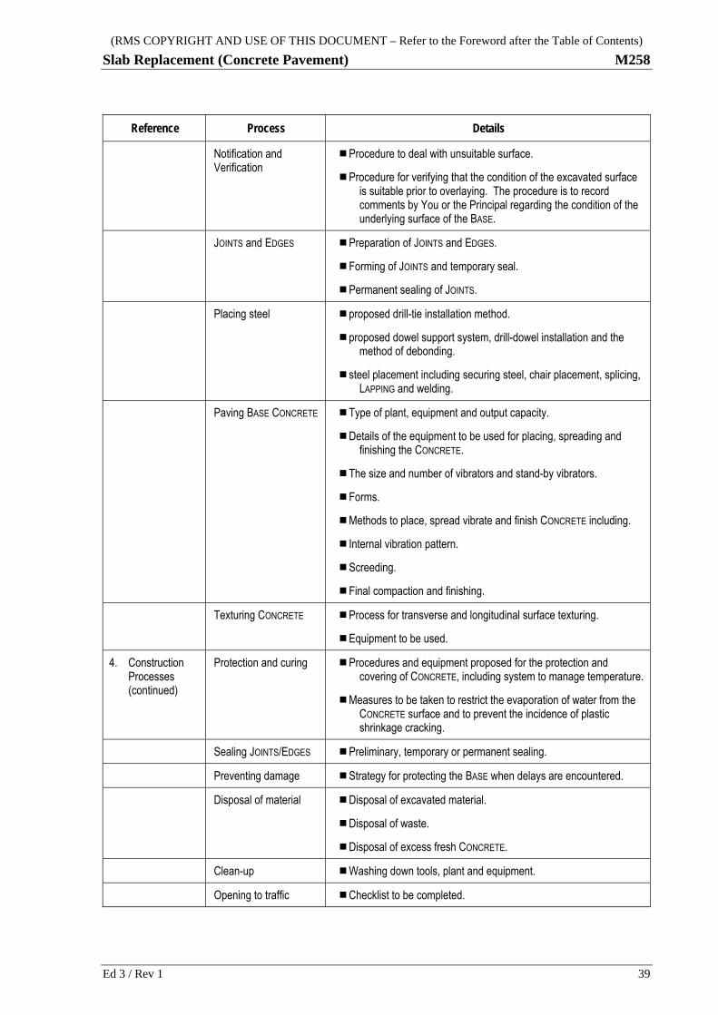
(RMS COPYRIGHT AND USE OF THIS DOCUMENT – Refer to the Foreword after the Table of Contents)
Slab Replacement (Concrete Pavement) M258
Reference Process Details
Notification and Verification
Procedure to deal with unsuitable surface.
Procedure for verifying that the condition of the excavated surface is suitable prior to overlaying. The procedure is to record comments by You or the Principal regarding the condition of the underlying surface of the BASE.
JOINTS and EDGES Preparation of JOINTS and EDGES.
Forming of JOINTS and temporary seal.
Permanent sealing of JOINTS.
Placing steel proposed drill-tie installation method.
proposed dowel support system, drill-dowel installation and the method of debonding.
steel placement including securing steel, chair placement, splicing, LAPPING and welding.
Paving BASE CONCRETE Type of plant, equipment and output capacity.
Details of the equipment to be used for placing, spreading and finishing the CONCRETE.
The size and number of vibrators and stand-by vibrators.
Forms.
Methods to place, spread vibrate and finish CONCRETE including.
Internal vibration pattern.
Screeding.
Final compaction and finishing.
Texturing CONCRETE Process for transverse and longitudinal surface texturing.
Equipment to be used.
4. Construction Processes (continued)
Protection and curing Procedures and equipment proposed for the protection and covering of CONCRETE, including system to manage temperature.
Measures to be taken to restrict the evaporation of water from the CONCRETE surface and to prevent the incidence of plastic shrinkage cracking.
Sealing JOINTS/EDGES Preliminary, temporary or permanent sealing.
Preventing damage Strategy for protecting the BASE when delays are encountered.
Disposal of material Disposal of excavated material.
Disposal of waste.
Disposal of excess fresh CONCRETE.
Clean-up Washing down tools, plant and equipment.
Opening to traffic Checklist to be completed.
Ed 3 / Rev 1 39

(RMS COPYRIGHT AND USE OF THIS DOCUMENT – Refer to the Foreword after the Table of Contents)
M258 Slab Replacement (Concrete Pavement)
ANNEXURES M258/E TO M258/K – (NOT USED)
ANNEXURE M258/L – ADDITIONAL TEST METHODS
L.1 INSPECTION FOR CONCRETE CRACKING
L.1.1 Cracking is categorised into unplanned structural cracks, induced cracks, plastic shrinkage cracks and drying shrinkage cracks.
Cracking in base slabs
L.1.2 Unplanned structural cracks are not induced cracks. They include drying shrinkage cracks in unreinforced SLABS (eg PCP).
Unplanned structural cracks
L.1.3 Induced cracking is a normal result of SLAB or joint construction (eg sawcuts are used to induce cracks).
Induced cracking
L.1.4 Plastic shrinkage cracks:
.1 Are discrete cracks of length less than 500 mm and of depth less than 50% of the BASE thickness.
.2 Form during the plastic stage of CONCRETE set.
Plastic shrinkage cracks
.3 Do not intersect a longitudinal EDGE or a formed joint (ie they are not an induced joint).
L.1.5 Drying shrinkage cracks consist of:
.1 JRCP, PCP-R and SFCP-R: occur in the central part of the SLAB, extend full depth and are continuous between JOINTS and/or EDGES.
.2 CRCP: full depth discrete transverse cracks without branches or convergences over the full width between longitudinal JOINTS or EDGES.
Non-structural cracks
L.1.6 Each new BASE SLAB must have cracking categorised and its extent estimated and results documented.
.1 Each PCP SLAB:
Cumulative length of plastic shrinkage cracks; less than 1m and greater than or equal to 1m in any SLAB,
Occurrence of unplanned structural cracks (including and drying shrinkage cracks),
Mark non-conforming SLABS.
Document results
40 Ed 3 / Rev 1

(RMS COPYRIGHT AND USE OF THIS DOCUMENT – Refer to the Foreword after the Table of Contents)
Slab Replacement (Concrete Pavement) M258
.2 CRCP, JRCP, SFCP-R and PCP-R SLABS:
Cumulative length of plastic shrinkage cracks; less than 1m and greater than or equal to 1m in any SLAB,
Occurrence of unplanned structural cracks (note: exclude drying shrinkage cracks),
Mark non-conforming SLABS.
ANNEXURE M258/M – REFERENCED DOCUMENTS AND
DEFINITIONS
M.1 REFERENCED DOCUMENTS
M.1.1 Australian Standards
AS 1012.3.1 Methods testing concrete - Determination of properties related to the consistency of concrete - Slump test
AS 1379 Specification and supply of concrete
AS 1554.3 Structural steel welding - Welding of reinforcing steel
AS 2870 Residential slabs and footings
AS 3799 Liquid membrane-forming curing compounds for concrete
AS/NZS 4671 Steel reinforcing materials
AS/NZS 4680 Hot-dip galvanized (zinc) coatings on fabricated ferrous articles
M.1.2 RMS Documents
RMS T862 Wax emulsion stability
RMS R82 Lean-mix Concrete Subbase
RMS R116 Heavy Duty Dense Graded Asphalt )
RMS R119 Open Graded Asphalt
RMS R121 Stone Mastic Asphalt
RMS R141 Pavement Markings
RMS R142 Raised Pavement Markers
RMS R143 Signposting
RMS R146 Pavement Marking Maintenance – Rural Regions
RMS Q Quality Management System
RMS 3201 Concrete for Maintenance
RMS 3204 Preformed Joint Fillers for Concrete Road Pavements and Structures
Ed 3 / Rev 1 41

(RMS COPYRIGHT AND USE OF THIS DOCUMENT – Refer to the Foreword after the Table of Contents)
M258 Slab Replacement (Concrete Pavement)
RMS 3254 Bitumen Emulsion
RMS 3263 Hot Poured Elastomeric Joint Sealant for Roads
RMS 3400 Manufacture and Delivery of Road Signs
Series MP Rigid Pavement Standard Details – Maintenance, Plain Concrete Pavement
M.2 ABBREVIATIONS AND DEFINED TERMS CRCP Continuously Reinforced CONCRETE Pavement (BASE).
FBL Finished Base Level - refer to Clause 3.2.
JRCP Jointed Reinforced CONCRETE Pavement (BASE) – dowelled.
LCS Lean-mix CONCRETE Subbase.
PCP Plain CONCRETE Pavement (BASE).
PQP Project Quality Plan according to RMS Q and this Specification
SFCP Steel Fibre Reinforced CONCRETE Pavement (BASE).
~ -R The '-R' suffix indicates that discrete SLABS contain reinforcement in the BASE.
ANCHOR A restraining beam cast in the ground, on which a BASE SLAB is later cast.
ANCHOR, TERMINAL A SLAB ANCHOR where the overlying BASE SLAB is a terminal SLAB.
ANCHOR SLAB The BASE SLAB which lies over an anchor.
APPROACH SLABS Pavement which is located within 15 m of bridges (or other structures) where the CONCRETE BASE is discontinuous or within 15 m of contract limits.
BATCH A quantity of CONCRETE containing a fixed amount of ingredients and produced in a discrete operation.
BASE The upper (structural) layer of CONCRETE with varying insitu strengths, typically 25 to 50 MPa. The CONCRETE contains various forms of steel reinforcement, dowels and tiebars. In some instances the CONCRETE may contain steel-fibre reinforcement.
BATCHING The process of combining the CONCRETE ingredients in fixed proportions by mass or by volume, including charging and mixing.
CONCRETE A thoroughly mixed combination of cement, aggregates and water, with or without the addition of chemical admixtures or other materials, all of which separately and when combined comply with the requirements of this Specification.
COMPLETION OF
BATCHING For mobile mixers, it will be the time at which mixing and slump adjustment ceases at the
BATCHING plant, or 10 minutes after the commencement of mixing, whichever occurs first.
DELIVERY TIME The elapsed time measured from the completion of BATCHING to arrival on site within 100 m of the point of placement.
EDGE, FREE This term is used in the context of limiting all restraint against the free movement of JOINTS which intersect that edge or joint. A free edge is provided by an isolation joint or by an OUTER
EDGE. Untied butt JOINTS and dowelled expansion JOINTS do not constitute free edges.
EDGE, OUTER (BASE) An edge against which material other than BASE or kerb CONCRETE is to be placed (such as granular backfill or no-fines CONCRETE).
42 Ed 3 / Rev 1

(RMS COPYRIGHT AND USE OF THIS DOCUMENT – Refer to the Foreword after the Table of Contents)
Slab Replacement (Concrete Pavement) M258
Ed 3 / Rev 1 43
EDGE, RELIEF An edge or joint, which relieves contraction stresses in JOINTS and/or sections and is aligned approximately parallel with that edge. A relief edge is provided by an untied joint, by a FREE
EDGE or by an expansion or isolation joint.
FIXED SURFACES FIXED SURFACES are surfaces that remain unaltered by the work. FIXED SURFACES include most existing structures, the existing pavement adjacent to the work, an existing cover on a public utility or an existing drainage system.
JOINT A planned discontinuity in the CONCRETE, other than an edge.
JOINT, FORMED All JOINTS except for induced JOINTS. This includes slipformed and fixed-formed JOINTS and edges.
JOINT, MISMATCHED A joint which terminates on the edge of a SLAB. Only tied JOINTS are allowed to mismatch.
LAP (IN
REINFORCEMENT) A splice in which the bars are in contact over the full lapped length, with sufficient ties to ensure
contact in the hardened CONCRETE.
LOAD A single truckload of CONCRETE comprising one or more BATCHES.
LOT As defined in RMS Q.
PAVEMENT COURSE
POSITION The pavement layers described in Figure 1.
NOMINATED
CONSTRUCTION
METHOD
The work procedure and method documented in the PROJECT QUALITY PLAN in accordance with Clause 2.
RETEMPERING The addition of water to a BATCH after COMPLETION OF BATCHING.
SLAB A portion of CONCRETE bounded by JOINTS and/or edges.
SLAB, ODD-SHAPED Odd-shaped SLABS are defined as:
1. A SLAB containing a block out for a drainage structure, or
2. A TRAFFICKED SLAB having a corner angle less than 84°, or the ratio of its longer to
shorter dimension(i) exceeding 1.25, or
3. An un-TRAFFICKED SLAB having a corner angle less than 80°, or the ratio of its longer
to shorter dimension(i) exceeding 3.0.
4. If dimensions measured normal and parallel to longitudinal JOINTS are variable within a SLAB, the greatest value of the ratio applies.
SLAB, MISMATCHED A SLAB in which an edge is intersected by a JOINT which does not continue through the subject SLAB. Only tied joints are allowed to mismatch.
TRAFFICKED SLAB A slab bounded by longitudinal JOINTS, which lies either totally or in part within the trafficked carriageway as defined by lane lines.
TRANSIT MIXER An item of plant or equipment which maintains the plastic CONCRETE in the mixed state. Consistent with common usage, this term is also used (for convenience) in lieu of “mobile BATCH mixer”.
WATER/BINDER RATIO The ratio of water to binder contained in the CONCRETE BATCH. Refer to RMS 3201.
LAST PAGE