nosp 15759-04-om-dm-tx6-x & dm-tt6-k
TRANSCRIPT

Operating Manual
NOSP15759-04 (07/2013)
MultiXplo / MultiTox Detectors
DM-TX6-X (Catalytic)
DM-TT6-K (Catharometer)

MultiXplo / MultiTox Page 2 / 56 NOSP15759-04 (07/2013)

MultiXplo / MultiTox Page 3 / 56 NOSP15759-04 (07/2013)
Note
This manual must be carefully read by those who are or will be responsible for the operation or maintenance of this product. The product may be less effective than expected if not used or maintained in accordance with the manufacturer's instructions.
The warranty made by Simtronics with respect to the product is voided if the product is not used and maintained as described in this manual.
Please read the general warnings in chapter 9.
© Simtronics SAS, all rights reserved.

MultiXplo / MultiTox Page 4 / 56 NOSP15759-04 (07/2013)
1. ProdUct description .................................................................................................................6
1.1. Application Fields .............................................................................................................6
1.2. DM-TX6-X ..........................................................................................................................6
1.3. DM-TT6-K ..........................................................................................................................7
1.4. Technical specifications ...................................................................................................7
1.5. Detection Cartridge ..........................................................................................................9
1.6. Wireless Configuration Tool.............................................................................................9
1.7. Product Code...................................................................................................................10
2. Technical features ..................................................................................................................12
3. Performances .........................................................................................................................14
4. Installation ..............................................................................................................................16
4.1. Positioning .......................................................................................................................16
4.2. Assembly .........................................................................................................................16
4.3. Electric connection .........................................................................................................19
4.4. Detection cartridge .........................................................................................................26
5. Commissioning .......................................................................................................................27
5.1. Visual inspection .............................................................................................................27
5.2. Power-up .........................................................................................................................27
5.3. Operational tests.............................................................................................................27
6. Operation.................................................................................................................................28
6.1. Environmental conditions ..............................................................................................28
6.2. Inhibition ..........................................................................................................................28
6.3. Signal current loop .........................................................................................................29
6.4. Alarm indication (LED) ...................................................................................................29
6.5. Wireless communication tool TLU600 ..........................................................................29
6.6. Information menu [INFO] ...............................................................................................32
6.7. Adjustment menu [ADJT] ...............................................................................................33
6.8. The maintenance menu [MAIN] .....................................................................................38
6.9. Ambiguity function in combustible gas detector smart sensors ................................39
7. HART communication.............................................................................................................40
8. Maintenance............................................................................................................................41
8.1. Periodic maintenance .....................................................................................................41
8.2. List of main faults ...........................................................................................................42
8.3. Replacing the cartridge ..................................................................................................43
8.4. Replacing the complete detector...................................................................................43
9. Warnings .................................................................................................................................44
9.1. Safety ...............................................................................................................................44

MultiXplo / MultiTox Page 5 / 56 NOSP15759-04 (07/2013)
9.2. Ownership and confidentiality........................................................................................44
10. Warranty ..............................................................................................................................44
11. Declaration of conformity ..................................................................................................45
11.1. Product standards ......................................................................................................45
11.2. Approvals .....................................................................................................................45
11.3. Marking ........................................................................................................................46
12. Accessories and spare parts .............................................................................................47
12.1. Spare parts ..................................................................................................................47
12.2. Accessories .................................................................................................................48
12.3. Gas table codes & range table codes ........................................................................50
13. Conformity certificate.........................................................................................................53
14. Contact details ....................................................................................................................55

MultiXplo / MultiTox Page 6 / 56 NOSP15759-04 (07/2013)
1. PRODUCT DESCRIPTION
The DM-TX6-X is designed to monitor explosions hazard induced by the presence of flammable gases or vapours (hydrogen, hydrocarbons, alcohol, etc…).
The DM-TT6-K is designed to monitor the gas concentration in %vol. induced by the presence of some special gases or vapours (hydrogen, helium, carbon dioxide, etc…).
The detector can be connected directly to a large range of traditional controllers or Programmable Logic Controllers (PLC).
The DM-TX6-X and the DM-TT6-K may be fully configured using the portable communication terminal (TLU600), providing flexibility to the user.
Thus, the calibration and the maintenance operations can be undertaken by a single operator.
The MultiXplo and MultiTox are also available for use in an addressable network system with
distributed intelligence, SYNTEL. For more information, please refer to the Syntel module interface operating manual.
1.1. Application Fields
The DM-TX6-X and the DM-TT6-K are suitable for indoor and outdoor uses and offer a fast response time. Typical applications include:
• Storage and use of combustible/flammable gases and vapours(DM-TX6-X),
• Monitoring of processes with flammable products • Hydrogen detection in inert atmosphere and in high
concentration (DM-TT6-K),
• Chemical and petrochemical plants • Pharmaceutical industry • LNG/LPG • Oil and gas facilities
1.2. DM-TX6-X
The detectors are calibrated on 100% LEL (Lower Explosive Limit) of a particular gas or vapour.
The DM-TX6-X is a MultiXplo detector based on a transducer with thermo-catalytic oxidation, which requires oxygen to function properly.
In the event of a long period without oxygen, the measurement will no longer be representative of the concentration of gases or vapours.
The characteristics of the device can also be altered by the presence of certain catalyst poisons such as silicone fumes, vapours of organometallic compounds and, to some extent by halogenated compounds.
MultiXplo / MultiTox Page 7 / 56 NOSP15759-04 (07/2013)
1.3. DM-TT6-K
The DM-TT6-K is a MultiTox detector, based on catharometric transducer. Its measurement
range is usually expressed in terms of %vol. relative to a particular gas (for example 5 %vol. H2, 5 %vol. He...).
The DM-TT6-K measurement principle is based on the heat exchange between a heated filament and a "cold" separation. The effectiveness of the exchange between those two elements depends, in particular, of the thermal conductivity value of the mixture which separate them.
This measurement principle is very stable, and able to operate with high gas concentrations.
In this configuration, the presence of oxygen is not essential, and catalytic poisoning is not an issue.
1.4. Technical specifications
Each detector is constructed as follows:
• A wall-mounted support secured by two screws, allows assembly of a cable gland
(M20) (optional) and up to three plugs. • An explosion-proof housing (epoxy coated aluminium or 316 SS) containing:
• A set of tropicalized electronic cards • An infrared communication head, located on the detector’s housing. It
allows communication with the remote control (TLU600).
• A colour coded cartridge. Yellow for Combustible Gas Detector with thermo-catalytic cells (DM-TX6-X) and brown for catharometers (DM-TT6-K). The cartridge is located in
the lower part of the detector, and it is connected to the detector body by an open ring leaving the label visible.

MultiXplo / MultiTox Page 8 / 56 NOSP15759-04 (07/2013)
Figure 1 : Layout Drawing
(Congestion see Figure 2)

MultiXplo / MultiTox Page 9 / 56 NOSP15759-04 (07/2013)
1.5. Detection Cartridge
Detection Cartridges are explosion proof designed.
They are common to all Simtronics MultiXplo and MultiTox-K products in order to reduce the number of spare parts.
• DM-RX6-X and DM-RT6-K: Line Network « Telecaptors » • DM-TX6-X and DM-TT6-K: Line « Telecaptors »
For combustible gas detector’s cartridges, if the difference between the storage temperature and the operating temperature does not exceed 20°C, the nominal characteristics are obtained after a few minutes. Otherwise, wait for the balancing thermal unit, about half an hour.
Catharometer cartridges (cartridges K) need to be in thermal balance with their environment to provide nominal performance. Thus, when the cartridges have been unpowered more than
half-an-hour, a warm-up time is required when power is restored. The duration of warm-up is usually range from ½ hour to 4 hours, depending on the temperature difference between the cartridge and the ambient temperature.
The cartridge temperature information is available on the TLU.
The cartridge must not be unplugged when the detector is powered.
1.6. Wireless Configuration Tool
Information and status of the detector are available via the wireless configuration tool TLU600/610.
Configuration and tests are performed using this wireless configuration tool (IrDA protocol).
This tool is common for all Simtronics MultiFlame, MultiXplo and MultiTox products.
The TLU600/610 provides access to devices, which would otherwise require major logistic operations for maintenance or for configuration (calibration …).
For more details, please refer to the wireless configuration tool operating manual.
Some versions are equipped with the HART communication protocol, Some versions are equipped with the HART communication protocol, Some versions are equipped with the HART communication protocol, Some versions are equipped with the HART communication protocol, enablingenablingenablingenabling
acces to the same functions as the TLU(see §acces to the same functions as the TLU(see §acces to the same functions as the TLU(see §acces to the same functions as the TLU(see §7777))))
MultiXplo / MultiTox Page 10 / 56 NOSP15759-04 (07/2013)
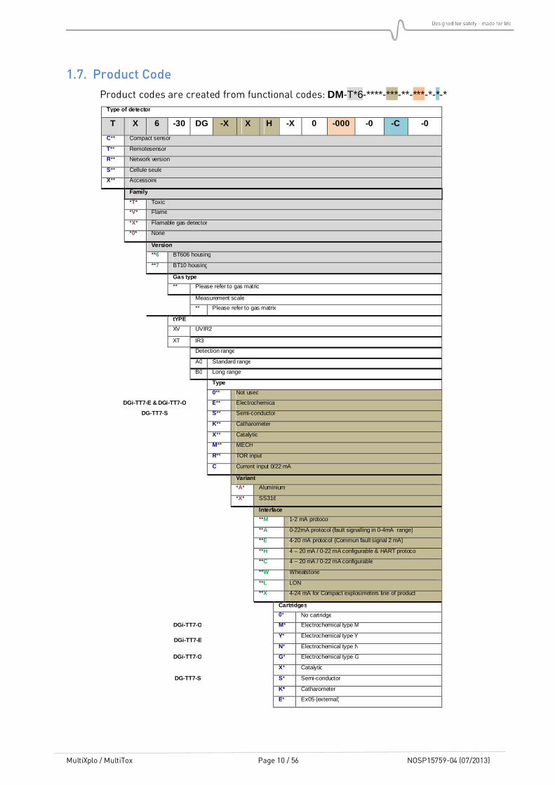
1.7. Product Code
Product codes are created from functional codes: DM-T*6-****-***-**-***-*-*-* Type of detector
T X 6 -30 DG -X X H -X 0 -000 -0 -C -0
C** Compact sensor
T** Remotesensor
R** Network version
S** Cellule seule
X** Accessoire
Family
*T* Toxic
*V* Flame
*X* Flamable gas detector
*0* None
Version
**6 BT606 housing
**7 BT10 housing
Gas type
** Please refer to gas matric
Measurement scale
** Please refer to gas matrix
tYPE
XV UVIR2
XT IR3
Detection range
A0 Standard range
B0 Long range
Type
0** Not used
DGi-TT7-E & DGi-TT7-O E** Electrochemical
DG-TT7-S S** Semi-conductor
K** Catharometer
X** Catalytic
M** MECH
R** TOR input
C Current input 0/22 mA
Variant
*A* Aluminium
*X* SS316
Interface
**M 1-2 mA protocol
**A 0-22mA protocol (fault signalling in 0-4mA range)
**E 4-20 mA protocol (Commun fault signal 2 mA)
**H 4 – 20 mA / 0-22 mA configurable & HART protocol
**C 4 – 20 mA / 0-22 mA configurable
**W Wheatstone
**L LON
**X 4-24 mA for Compact explosimeters line of product
Cartridges
0* No cartridge
DGi-TT7-O M* Electrochemical type M
DGi-TT7-E Y* Electrochemical type Y
N* Electrochemical type N
DGi-TT7-O G* Electrochemical type G
X* Catalytic
DG-TT7-S S* Semi-conductor
K* Catharometer
E* Ex05 (external)

MultiXplo / MultiTox Page 11 / 56 NOSP15759-04 (07/2013)
T X 6 -30 DG -X X H -X 0 -000 -0 -C -0
Semicond.Sensor type & special configurations
*0 Not specified
DG-TT7-S
*A 20
*B 23
*C 24
*D 25
*E 27
*F 30
Applicable to version other than –S type
*M Special version MarED (TX and TV)
*N Special version with ALRM LED not memorized (not in compliance with EN 54-10) (flame version only)
Configuration
000 Standard
00A Absolutely no grease
00B MED version
00C Not CE DPC version (not memorized ALRM)
00D IRDA cap instead of display
00E 0V connected to housing ground on Tox type C
00F TCM02 instead of IRDA cap
Language
0 Fr / GB
F French
E English
Hardware version
A Type 63
B Type 65
C Type 67 (HART)
Software version
0 Standard

MultiXplo / MultiTox Page 12 / 56 NOSP15759-04 (07/2013)
2. TECHNICAL FEATURES
GENERAL
Type Gas detector
DM-TX6-X MultiXplo (catalytic gas detector)
DM-TT6-K MultiTox (catharometer gas detector)
DM-RX6 or DM-RT6 Network detector
Calibration Factory set, recommended test every 6 months
OUTPUT SIGNALS
4-20mA loop signal Type active (source) maximum load impedance 700Ω E version - « 4-20mA » 4-20mA with one fault level
- 0% full scale 4 mA
- 100% full scale 20 mA
- 105% full scale 20.8 mA
- Ambiguity function 21.7 mA (DM-TX6-X)
- Fault or inhibition 2 mA
A version - « 0-22mA » 4-20mA with several fault levels, for PLC and some recent control units
- 0% full scale 4 mA
- 100% full scale 20 mA
- >105% full scale 20.8 mA
- Ambiguity function 21.7mA (DM-TX6-X)
- Inhibition 3.4 mA
- Fault measure 2.6 mA
- Device fault (HW/SW) 2.0 mA
Output relays 2 x configurable relays max 1A / 30V AC/DC
ELECTRICAL
Power supply 24VDC, (18 – 28 V DC versions DM-T#6)
(18 – 30 V DC versions DM-R#6)
Consumption 2W maximum
Wiring 0,3mm² (22AWG)-1,5mm² (16AWG).
MTBF 164 000h (Version DM-T#6) out of the sensing element)
ENVIRONNEMENT
Storage temperature -30°C to +70°C (2 years in « clean » atmosphere)
Temperature range -20°C to +60°C
Pressure 1013 Hpa ± 10%
Humidity 95% RH (non-condensable)

MultiXplo / MultiTox Page 13 / 56 NOSP15759-04 (07/2013)
Protection IP66
RFI/EMI (DM-TX6-X) EN 50270
IEC 60092-504, IEC 60533 and EN60945 (version config 00B)
Warm-up time (DM-TX6-X) < 100 sec
Stabilisation time (DM-TX6-X) < 190 sec
PERFORMANCE (DM-TX6-X)
European EN 60079-29-1
EXPLOSION PROOF HOUSING
Material stainless steel 316 L or epoxy coated aluminium
Weight 6.4 kg (14.3 Lbs.) (Stainless steel)
1.8kg (4Lbs) (Aluminium)
ATEX/IECEx II 2 G / Ex d II C T6 Gb
- 20°C < Ta < + 65°C
Dimensions
Figure 2: Outline drawing
MultiXplo / MultiTox Page 14 / 56 NOSP15759-04 (07/2013)
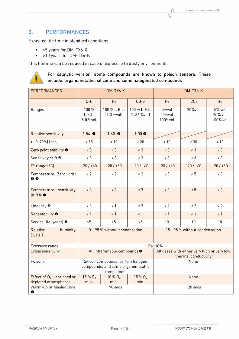
3. PERFORMANCES
Expected life time in standard conditions:
• >5 years for DM-TX6-X • >10 years for DM-TT6-K
This lifetime can be reduced in case of exposure to dusty environments.
For catalytic version, some compounds are known to poison sensors. These
include, organometallic, silicone and some halogenated compounds
PERFORMANCES
DM-TX6-X DM-TT6-K
CH4 H2 C4H10 H2 CO2 He
Ranges 100 % L.E.L.
(5.0 %vol)
100 % L.E.L. (4.0 %vol)
100 % L.E.L. (1.86 %vol)
5%vol 20%vol 100%vol
20%vol 5% vol 20% vol 100% vol
Relative sensitivity 1.54 1.60 1.00
τ (0-90%) (sec) < 15 < 10 < 20 < 10 < 30 < 10
Zero point stability < 3 < 3 < 3 < 3 < 3 < 3
Sensitivity drift < 3 < 3 < 3 < 3 < 3 < 3
T° range (°C) -20 / +60 -20 / +60 -20 / +60 -20 / +60 -20 / +60 -20 / +60
Temperature Zero drift
< 2 < 2 < 2 < 3 < 5 < 3
Temperature sensitivity drift
< 3 < 3 < 3 < 3 < 5 < 3
Linearity < 3 < 1 < 3 < 2 < 2 < 2
Repeatability < 1 < 1 < 1 < 1 < 1 < 1
Service life (years) >5 >5 >5 10 10 10
Relative humidity (% RH)
0 – 95 % without condensation 15 - 95 % without condensation
Pressure range Pa±10% Cross sensitivity All inflammable compounds All gases with either very high or very low
thermal conductivity Poisons Silicon compounds, certain halogen
compounds, and some organometallic compounds.
None
Effect of O2 –enriched or depleted atmospheres
15 % O2 min.
10 % O2 min.
15 % O2 min.
None
Warm-up or biasing time
90 secs 120 secs
MultiXplo / MultiTox Page 15 / 56 NOSP15759-04 (07/2013)
Measured at 50 % LEL of the considered gas
In % full scale
On the range: -10°C to +40°C.
(In years) Expected values based on “typical” site operating conditions without poison or corrosive compounds.
Lifetime can significantly vary (better or worse) depending on real site conditions.
Measure is available but full performances may require longer time. (See Chapter 2).
As soon as a gas or vapour is flammable, it is may be sensed by the combustible gas detector.
Sensitivity (regarding LEL range) and the response time depend on the compound. In broad terms we can say that bigger the molecule is, longer is the response time and lower is the sensitivity.

MultiXplo / MultiTox Page 16 / 56 NOSP15759-04 (07/2013)
4. INSTALLATION
Detectors described in this manual are safety instruments intended to be installed in explosive
atmospheres and have been designed in compliance with standards EN60079-0 and EN60079-1, EN 60079-29-1, CEI 60079-0 and CEI 60079-1.
Intervention in some sites may be subject to restrictions that we invite you to follow
for your own safety and those of others.
4.1. Positioning
The remote sensor must be positioned as close as possible to sources of potential leakage, taking into account airflows (e.g. upper and lower ventilation). The height is determined by the density of the gas to detect.
Generally speaking, a detector will not be placed in front of an air inlet that brings clean air
This height may be adjust to take into account the specific conditions which may interfere on the risk level (gas density, ambient temperature…)
4.2. Assembly
Use two 6 mm diameter screws to secure the support.
It is highly recommended to install the support with cable-gland downward in order to avoid
water infiltrations. In case of horizontal position, it is advised to make one or two loops with the cable at the entry of the cable-gland.
On stainless steel housings, plugs are sealed with Loctite. If the plugs are moved or removed, it must be sealed again, using Loctite or equivalent.
On aluminium housings, plugs are equipped with seals.
Figure 3: Drilling dimensions for support fixing.

MultiXplo / MultiTox Page 17 / 56 NOSP15759-04 (07/2013)
4.2.1. Detector’s assembly Check the presence of the O-ring on the explosion proof seal, make sure that it is correctly greased and has no visible damage.
Plug the connectors to the base, as described in paragraph “Electric connection”.
Fit the main housing on the base, placing the excess of cable in the base.
Make sure to correctly tighten the 2 fixing screws once the correct position has
been obtained.
Figure 4 : Housing orientation
4.2.2. Orientation of the communication head The IR communication head can be rotated from top to bottom in order to optimize the connection with the wireless communication tool. Avoid direct sunlight on head.
Once the correct position has been obtained, tighten the stopping screw to set the adjustment.
A 1.5 mm Allen wrench is required for this operation.
Do not touch the anti-removal screw of the IR communication head which is masked
by the label “Do not retire”.
MultiXplo / MultiTox Page 18 / 56 NOSP15759-04 (07/2013)
4.2.3. Cable‘s inputs (as an option)
Connection cables must pass through a cable gland (Explosion Proof certified)
For installation details, refer to the instructions provided by the manufacturer of the cable gland used.
The unassigned cable glands entries must be blanked with explosion proof certified
plugs (M20). On stainless steel version, they are glued with Loctite or equivalent
compound. If a plug is moved or removed, it must be glued again with Loctite or an
equivalent.

MultiXplo / MultiTox Page 19 / 56 NOSP15759-04 (07/2013)
4.3. Electric connection
Never adjust electric connections when detectors are powered. Maintenance must
be undertaken by qualified staff. Observe safety site rules.
The MultiXplo and MultiTox are sensors with standard current output (4-20mA or 0-22mA).
The connection can be on 3 or 4 wires. The 4 wires configuration allows insulation between the signal and power loops.
In addition, two independent relays outputs can be connected directly to a controller or signal device.
We recommend using an armoured and shielded cable, type NF M 87 202, in accordance with the requirements for hazardous areas and NF C 15 100. Other cables can be used if they are compliant with the local regulations and standards.
The table below shows the maximum cable lengths (2-wires) based on a minimum supply voltage.
Min. single wire cross area mm²/AWG 0.5 (20) 0.9 (18) 1.5 (16)
Supply voltage 20VDC, max. cable length in m/ft.* 250/820 400/1310 700/2300
Supply voltage 24VDC, max. cable length in m/ft.* 650/2130 1100/3600 2000/6560
* Those values are indicative ones, for a considered consumption power about 3.5 W
4.3.1. Installation recommendation This detector version is supplied in an electronic version TypeTypeTypeType----CCCC. The terminal V- is isolated from the electric ground of the housing
The detector is supplied with a configurable current
output type C (4-20 mA, factory configuration). But it can be modified in format 0-22 mA by the user, using one of the menus of the TLU 600.
Example: DMDMDMDM-**6-****-**C-**-***-*-C-*
This electronic Type C also allows the detector to get a HART output (as an option) superimposed to the output
current. The current output format follows the same logic as the one described above but the product code contains an H:
Example: DMDMDMDM-**6-****-**H-**-***-*-C-*
That version also embeds two electrical connectors for the two relays.

MultiXplo / MultiTox Page 20 / 56 NOSP15759-04 (07/2013)
Terminal blocks
Point JP12 & JP13 Description
1 T2 Relay 2
2 C2 Relay 2
3 T1 Relay 1
4 C1 Relay 1
Point JP11 Description
1 V- 0 V
2 V+ +24VDC power supply
3 V+ +24VDC power supply loop (connected to point 2)
4 V- 0 V, Connected to point 1
5 L+ 20mA Current loop: entry
6 L- 20mA Current loop: output
4.3.2. Connection of the electrical ground braid The braid is wrapped around the sheath. The mechanical bridge retains the cable and makes the electrical contact.
4.3.3. Grounding Local ground connection is located on the base of the detector.
It is recommended to use a yellow / green wire with a ring lug (minimum diameter 1.5 mm). The armour of the power cable is normally connected to the ground of the detector, but it may depend on site practices.
MultiXplo / MultiTox Page 21 / 56 NOSP15759-04 (07/2013)
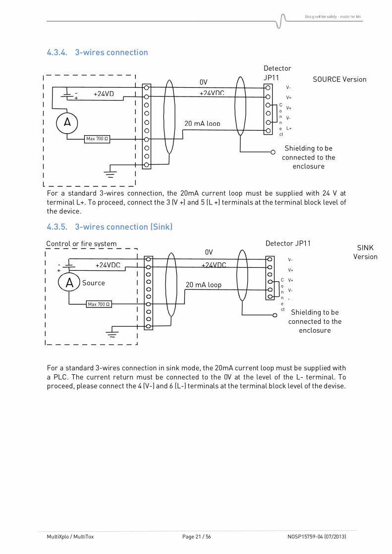
4.3.4. 3-wires connection
For a standard 3-wires connection, the 20mA current loop must be supplied with 24 V at terminal L+. To proceed, connect the 3 (V +) and 5 (L +) terminals at the terminal block level of the device.
4.3.5. 3-wires connection (Sink)
For a standard 3-wires connection in sink mode, the 20mA current loop must be supplied with a PLC. The current return must be connected to the 0V at the level of the L- terminal. To proceed, please connect the 4 (V-) and 6 (L-) terminals at the terminal block level of the devise.
A
0V
+24VDC retour
+24VDC
Max 700 Ω
V-
V+
V+
V-
L+
Detector JP11 Control or fire system
Source
Shielding to be connected to the
enclosure
20 mA loop
SINK Version
+ -
Connect
SOURCE Version
A
0V
+24VDC +24VD
Max 700 Ω
V-
V+
V+
V-
L+
Detector
JP11
Connect
Shielding to be connected to the
enclosure
20 mA loop
+ -

MultiXplo / MultiTox Page 22 / 56 NOSP15759-04 (07/2013)
4.3.6. 4-wires connection (isolated power)
When using a 4 wires connection, the current loop is provided by the input module or PLC. The loop (L + and L-) is optically isolated from the detector. The 4-20mA or 0-22mA input module
of the PLC has to power up the current loop with, at least 8V at the terminal level, for 22 mA. This reduces the resistance of the loop as defined in the relationship below.
mA22
V8tagesupply volPower maxi R
−=
In practice, the total loop resistance should not exceed 450 Ω with a voltage >18Vdc
4.3.7. Relay
The two relays can be configured normally closed or normally open. If normally open, the relays are opened when they are not powered (power loss).
The circuits’ relays are isolated from each other and from other parts of the detector. The two relays can be activated on one or more states of the detector, as shown below:
Activated on Relay 1
“Alarm”
Relay 2
“Fault”
Comments
Alarm Normally Open 4 possible levels
Fault Normally closed 2 types of fault
Inhibition Normally closed 2 types of inhibition
Control unit
4 wires Version
A
0V
+24VDC +24VD
Typ < 450 Ω
V-
V+
V+
V-
L+
Detector JP11
Fire or control system
Shielding to be
connected to the enclosure
20 mA loop
+ -
+24VD
+ -
JP12 or JP13
MultiXplo / MultiTox Page 23 / 56 NOSP15759-04 (07/2013)
With an electronic configuration type C, two terminal blocks are available. The pins are connected to each other, from a terminal to the other one.
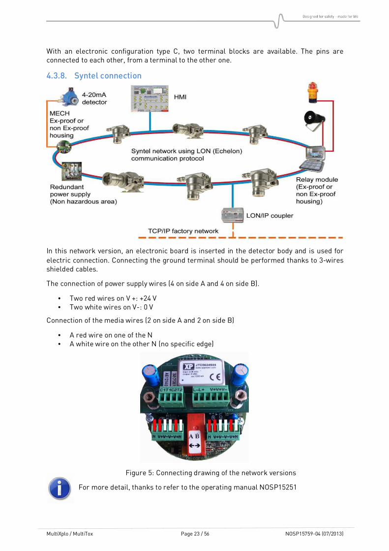
4.3.8. Syntel connection
In this network version, an electronic board is inserted in the detector body and is used for
electric connection. Connecting the ground terminal should be performed thanks to 3-wires shielded cables.
The connection of power supply wires (4 on side A and 4 on side B).
• Two red wires on V +: +24 V • Two white wires on V-: 0 V
Connection of the media wires (2 on side A and 2 on side B)
• A red wire on one of the N • A white wire on the other N (no specific edge)
Figure 5: Connecting drawing of the network versions
For more detail, thanks to refer to the operating manual NOSP15251

MultiXplo / MultiTox Page 24 / 56 NOSP15759-04 (07/2013)
4.3.9. 0-22mA input connection
In one of its inputs type, type (C): DDDDMMMM-**6-****-C**-**-***-*-*-* the device enables to use a 0-22mA input from another sensor.
In that case, an inputs of the cable gland or an accessory in replacement of the cartridge enables the connection between the hosted sensor and the device.
In order to operate this analogue input, an additional electronic card (PIE 3508 or PIE 3509) is added above the numeric card
The hosted sensor NEEDS to get its own power
Using this board leads to a connection between 0V from power supply and housing
ground.

MultiXplo / MultiTox Page 25 / 56 NOSP15759-04 (07/2013)
4.3.10. Ex05 input connection
It is possible to configure a device with an Ex05 remote explosimeter probe. In the below configuration, the input is of type Combustible Gas Detector (X) and the cartridge is of type E.
The device is designed as: DDDDMMMM-**6-****-X**-E*-***-*-*-*
In that case, an input of the cable gland or an accessory in replacement of the cartridge enables the connection between the hosted sensor and the device.
In order to operate this analogue input, an additional electronic card (PIE3521) is added above the numeric card.
Using this board leads to a connection between 0V from power supply and housing
ground.

MultiXplo / MultiTox Page 26 / 56 NOSP15759-04 (07/2013)
4.4. Detection cartridge
The cartridge is separated from the detector to enable its replacement. Its dismantling is extremely easy and does not need to touch the rest of the unit.
Caution during the assembly and the disassembly of the cartridge on the detector:
• Slide the positioning pin of the cartridge into the corresponding hole in the
housing (at the bottom of the receiver).
• Take care to not damage the cartridge connector when tightening the two
parts.
• This operation imperatively requires power to be off
Loosen the locking screw on the side of the nut (see Figure
1), then unscrew the nut, along the first part of the thread. With the nut, pull on the cartridge to remove it and then unscrew the cartridge from the nut.
Cartridges have an identification colour ring (see §1.4).
Insert a new cartridge of the same colour into the case respecting the position defined by the centring pin, screw the
nut until it stops ensuring the presence of O-ring. Then, tighten the locking screw.
Switch on the device in order to make the calibration of the new cartridge and the zero adjustment.
MultiXplo / MultiTox Page 27 / 56 NOSP15759-04 (07/2013)
5. COMMISSIONING
5.1. Visual inspection
Make certain that all the operations of the “Installation” chapter have been achieved correctly.
Pay particular attention on installation conformity, check the cables entry, the presence of O-rings, and the connection of the cartridge.
• The label on the smart sensor indicates the type of detector, the type of gas and the range for which the instrument has been calibrated,
• The cartridge colour must correspond to the type of detector: yellow for combustible gas, brown for catharometer.
5.2. Power-up
The smart sensor is powered through the multichannel detection unit or the Programmable Logic Controller. It results in the flashing of the green LED in the communication head.
5.3. Operational tests
All MultiXplo / MultiTox detectors are delivered set and tested. Some additional tests are necessary to check the good working of the loop. Please make sure to have all authorizations needed before running the following operations:
• Check the states/information using the wireless configuration tool (TLU), • Check the alarm levels • Zero point:
If there are no polluting gases or, if necessary, by injecting clean air at 30 l/h using the calibration kit equipped with an air cylinder
• Sensitivity: By injecting a suitable gas mixture at 30 l/h using the calibration kit
• Check the servo controls

MultiXplo / MultiTox Page 28 / 56 NOSP15759-04 (07/2013)
6. OPERATION
6.1. Environmental conditions
The lifetime of the catalytic cartridge depends on the operating environment related to certain pollutants.
Take care to avoid exposures to some vapours products as silicone (vapours of some paintings, some seals ...), halogenated products (molecules containing one atom of chlorine, fluorine, bromine) or as sulphur ones (H2S ...).
6.2. Inhibition
Maintenance Inhibition is temporary. It appears during power up and maintenance phases. Inhibition stops automatically when the operator get out of the maintenance menus or 10 minutes after the end of communication with the TLU.
Maintenance inhibition can be configured in "frozen" mode (factory setting) or in "free" mode.
• In "frozen" mode, outputs (current and relay) remain in their previous state. For example, if the device indicated a failure (2.0 mA), this state would be maintained
during the inhibition. • If the unit is configured in "free" inhibition mode, the output current will be on the same
level as for the permanent inhibition
The permanent inhibition is activated by an order issued by the TLU when an operation is performed at/or around the device, or when the operator wants to inhibit a faulty device. The permanent inhibition must be removed by an operator’s deliberate action using the TLU.

MultiXplo / MultiTox Page 29 / 56 NOSP15759-04 (07/2013)
6.3. Signal current loop
State “4-20” [mA]
“0-22” [mA]
TLU state
Line fault 0.0 0.0 Configuration fault 2.0 2.0 DEF Detector fault (electronic) 2.0 2.0 DEF Measure fault 2.0 2.6 DEF
Start inhibition 2.0 3.4 Warming up
remaining time including power up
Permanent inhibition 2.0 3.4 INH Maintenance inhibition Fixed configuration (fault) / (“free mode ”) *
Previous value/ (2.0)
Previous value/ (3.4)
INH
Alarm verification 21.7 21.7 DOUT
0% of full scale 4.0 4.0 No detection No alarm
25% of full scale 8.0 8.0 Alarm if overran
level
50% of full scale 12.0 12.0 Alarm if overran
level
75% of full scale 16.0 16.0 Alarm if overran
level
100% of full scale 20.0 20.0 Alarm 105% of full scale 20.8 20.8 Alarm
(*) Maintenance inhibition may be available in frozen or free mode.
6.4. Alarm indication (LED)
A red LED located in the head of communication flashes in case of confirmed alarm status.
• Flashing 1 Hz: Level 1 • Flashing 3 Hz: Level 2
If the alarm memorization is activated, the LED continues to flash until the alarm is acknowledged with the TLU or until the detector is powered off, then powered on again.
If the alarm memorization is disabled, the LED stops flashing when the alarm fades.
6.5. Wireless communication tool TLU600
All settings and tests of detectors can be done by the wireless communication tool TLU600. This communication tool and its software are compatible with all Simtronics detectors: MultiFlame, MultiTox and MultiXplo. Communication is made via infrared link (IrDA), similar but more efficient than infrared links for computers. IrDA head should not be placed facing the sun as it significantly reduces the communication with the TLU600.
Please refer to the wireless communication tool operating manual for more details.
MultiXplo / MultiTox Page 30 / 56 NOSP15759-04 (07/2013)
The TLU600 menu is composed of 2 access levels allowing both settings and obtaining information about detector’s status.
• level 1 : exploitation • level 2 : Maintenance
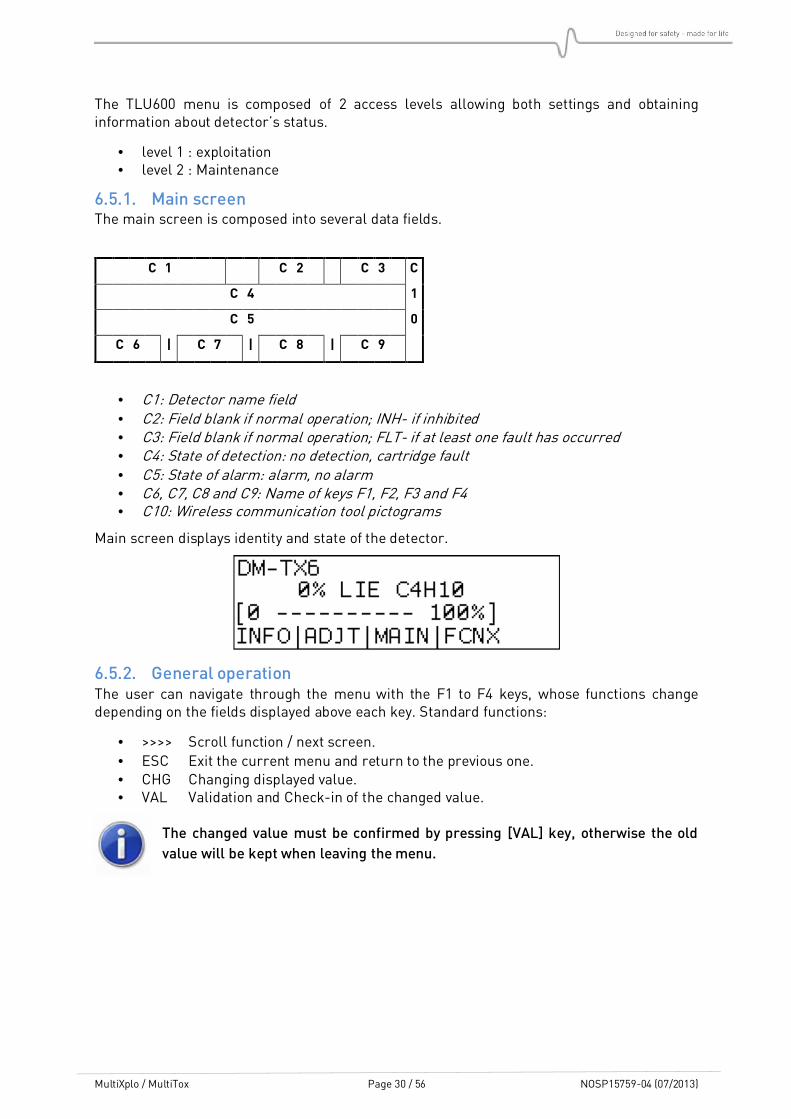
6.5.1. Main screen The main screen is composed into several data fields.
C 1 C 2 C 3 C
C 4 1
C 5 0
C 6 | C 7 | C 8 | C 9
• C1: Detector name field • C2: Field blank if normal operation; INH- if inhibited • C3: Field blank if normal operation; FLT- if at least one fault has occurred • C4: State of detection: no detection, cartridge fault • C5: State of alarm: alarm, no alarm • C6, C7, C8 and C9: Name of keys F1, F2, F3 and F4 • C10: Wireless communication tool pictograms
Main screen displays identity and state of the detector.
6.5.2. General operation The user can navigate through the menu with the F1 to F4 keys, whose functions change depending on the fields displayed above each key. Standard functions:
• >>>> Scroll function / next screen.
• ESC Exit the current menu and return to the previous one. • CHG Changing displayed value. • VAL Validation and Check-in of the changed value.
The changed value must be confirmed by pressing [VAL] key, otherwise the old
value will be kept when leaving the menu.
MultiXplo / MultiTox Page 31 / 56 NOSP15759-04 (07/2013)
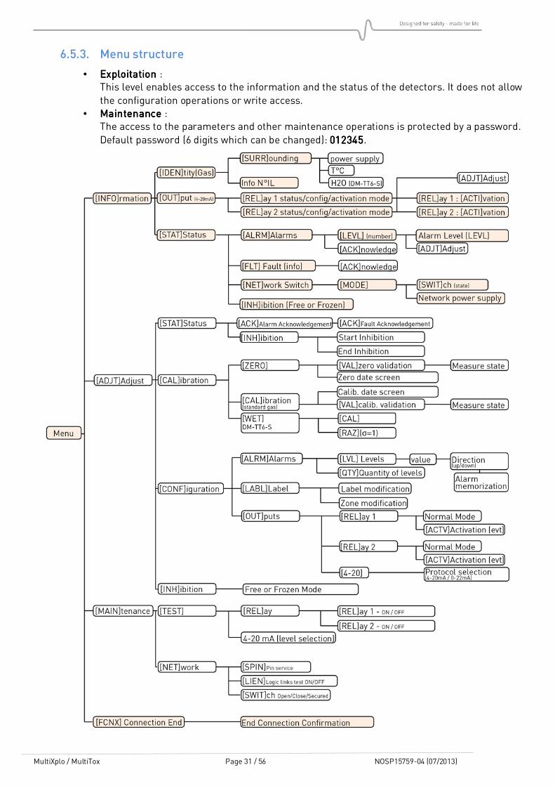
6.5.3. Menu structure
• ExploitationExploitationExploitationExploitation : This level enables access to the information and the status of the detectors. It does not allow
the configuration operations or write access. • MaintenanceMaintenanceMaintenanceMaintenance :
The access to the parameters and other maintenance operations is protected by a password.
Default password (6 digits which can be changed): 012345012345012345012345.

MultiXplo / MultiTox Page 32 / 56 NOSP15759-04 (07/2013)
6.6. Information menu [INFO]
The information menu contains all information concerning the identity and settings of the detector. The first screen gives the detectors reference and its serial number.
6.6.1. [IDEN]tity submenu Presentation of:
• The serial number • The device reference • The scale and the targeted gas
Sub-menus present the board software version, the power supply voltage and the temperature read in the cartridge.
6.6.2. [OUT]put submenu Presentation of:
• Current protocol (0-20 mA or 4-20 mA).
• Normal state of the relays (normally open or normally closed). • Condition of relays activation.
Relays can be set with a level 2 access.
6.6.3. [STAT]e Information submenu Presentation of:
• Number and value of activated alarm levels.
• List of eventual faults (press F1 key to scroll through the list) • Possibility to acknowledge alarms • Possibility to acknowledge ambiguity (DM-TX6)
6.6.3.1. [ALRM] Alarm screen Allows setting of levels and alarms acknowledgement.
6.6.3.2. [FLT.] Fault screen Displays a list of eventual faults (press F1 key to scroll through the list) and allows their acknowledgment.
6.6.3.3. Network screen: switch state This menu and its sub-menus are used for the network detector settings. For any further details, please refer to the Syntel system operating manuals.
MODE SCREENMODE SCREENMODE SCREENMODE SCREEN
The first line shows the operating mode of the sensor in the network (logic link test / out of
order / emulation). The second line shows if the network part of the detector is “operating” or “out of order”. For any further details, please refer to the Syntel system operating manuals.
NETWORK NETWORK NETWORK NETWORK SCREEN:SCREEN:SCREEN:SCREEN: ALIMALIMALIMALIM
Information displayed:
• Voltage A: ON / OFF • Voltage B: ON / OFF
For any further details, please refer to the Syntel system operating manuals

MultiXplo / MultiTox Page 33 / 56 NOSP15759-04 (07/2013)
6.6.3.4. The INH screen: This screen is dedicated to verify the inhibition mode configuration (frozen or free). If the access level permits it, it is possible to change this setting.
6.7. Adjustment menu [ADJT]
This menu presents all the detector settings. All the functionalities, except alarm level acknowledgment, request access level 2.
6.7.1. [STAT]us sub-menu 6.7.1.1. Alarm Acknowledgement
This menu enables the acknowledgement of the memorized alarms. The alarm can be acknowledged only if the alarm condition has disappeared.
6.7.1.2. Inhibition / End of inhibition
The inhibition (called permanent inhibition) is activated or deactivated manually using the menu. This function is used for deactivating the detector outputs (example: during maintenance).
The « inhibition » menu is available if the sensor is not in inhibition, maintenance inhibition or simulation.
Selecting the inhibition mode will switch the detector in inhibition mode.
The message “End of inhibition” is displayed on the TLU.
Press on “End of inhibition” to get the detector back to normal operating mode.

MultiXplo / MultiTox Page 34 / 56 NOSP15759-04 (07/2013)
6.7.2. CALIBRATION sub-menu 6.7.2.1. Zero point setting
The operator can set the zero point with the wireless communication tool TLU600/610.
The detector is in maintenance inhibition mode for 10 minutes after it goes back to main screen. Use the setting menu and validate the INH command for acknowledgement.
Press F4 key to stop communication between TLU600/610 and the detector.

MultiXplo / MultiTox Page 35 / 56 NOSP15759-04 (07/2013)
6.7.2.2. Calibration
Calibration must be made with the gas the detector is set to detect, with the SET menu (F2 key)
of the wireless communication tool TLU600/610 and a calibration kit. The calibration gas should be injected at a flow rate between 30 l/h and 60 l/h.
The detector is in maintenance inhibition mode for 10 minutes after it goes back to main screen. Use the setting menu and validate the INH command for acknowledgement.
To end of communication between the TLU600/610 and the detector is done by pressing F4 key on main menu.

MultiXplo / MultiTox Page 36 / 56 NOSP15759-04 (07/2013)
6.7.3. [CONF]iguration 6.7.3.1. Alarm sub-menu
The menu gives access to:
• The number of alarms levels used (0 to 4).
• The trigger’s value of the alarm (levels values) • The alarm trigger sense (up/down) • The alarm memorization (yes/no)
On one hand, the alarm memorization maintains relays and alarm information on the wireless communication tool. On the other hand, the current output and the concentration displayed on
the wireless communication tool are always updated with the real concentration.
6.7.3.2. Label and zone sub-menu This menu allows label and zone’s modification. After selecting a label or a zone, the modification function operates in the same manner.
The numeric keys correspond to different alphanumeric characters. For each displayed page, the numeric keys have a different assignment.
Both “Label” and “Zone” fields are free text type for identification of the detector (name and position of the detector).
To edit fields, select [label] or [zone].
• Press on the corresponding numeric key to select a figure. • Press [>>>>>>>>] to go to the next figure in the field. • Press [PAGE] to go next page.
The label or zone modification must be confirmed by pressing the key VALLLLID, otherwise the
modification is not taken into account
6.7.3.3. Output configuration sub-menu [Adjust] / [Config] / [Outputs]
This menu gives access to the configuration of the relay operating mode and to conditions of activations.
State of the relays: Each relay can be configured:
• Normally open (not energized) • Normally closed (energized)
Activation of the relays: Each relay can be activated on one or several following conditions:
• Alarm • Fault • Inhibition
Factory setting:
• Relay 1: normally open (not energized) activated on alarm levels • Relay 2: normally closed (energised) activated by any fault or inhibition
This menu allows you to switch the format of the output current between 4-20 mA and 0-22 mA.

MultiXplo / MultiTox Page 37 / 56 NOSP15759-04 (07/2013)
6.7.4. [INH]ibition submenu Maintenance inhibition can be configured in « frozen » mode (factory setting) or « free » mode. For further details, please, refer to §6.2
MultiXplo / MultiTox Page 38 / 56 NOSP15759-04 (07/2013)
6.8. The maintenance menu [MAIN]
The maintenance menu allows the user to check if the detector is in normal operation
conditions
• (Test of the relay and current outputs).
6.8.1. TEST sub-menu 6.8.1.1. Relay menu
This menu gives access to activation or deactivation of the relays.
The detector goes to inhibition mode. The detector will stay in inhibition mode if the user goes
back through the steps to the main menu. Otherwise, the detector will return to its “current” state.
6.8.1.2. The 4-20 mA screen This menu allows the output current to be set at a chosen value. The possible output values are: 2mA, 4mA, 8mA, 12mA, 16mA, 20mA or 22mA.
During this phase, the detector goes automatically to inhibition mode. The detector will stay in
inhibition mode if the user goes back through the steps to the main menu. Otherwise, the detector will return to its “current” state.
6.8.2. NETWORK sub-menu This menu gives direct access to different tests for the network. For any further details, please refer to the additional network operating manual:
• SPIN sends the detectors network identification. • LIEN switches from normal mode to logic link mode. • SWITCH enables the switches to go on mode open/closed/open secured.

MultiXplo / MultiTox Page 39 / 56 NOSP15759-04 (07/2013)
6.9. Ambiguity function in combustible gas detector smart sensors
In compliance with applicable standards, the ambiguity function is activated when a detected
gas concentration rises above 120% LEL. The signal is locked at 21.7 mA to protect against any false measurement due to oxygen deficiency.
This function also cuts the power to the cartridge to avoid damaging the sensitive element.
The measurement signal can only be unlocked by the operator using the
TLU600/610 remote control unit. Before that, the non-presence of inflammable gas
or vapour in atmosphere must be control by the user.
Even switching the power off and power on again from the control room will not
unlock the signal.
The TLU displays the following screen:
To clear the ambiguity, follow the instruction below with the TLU600:
INFO / STAT / ALRM / ACK. (YES)INFO / STAT / ALRM / ACK. (YES)INFO / STAT / ALRM / ACK. (YES)INFO / STAT / ALRM / ACK. (YES)
The device then goes in warm-up mode (refer to §6.3) for 90s. The detector is in inhibition mode. The current output and the default relay (if factory configuration) are consequently activated.
A warming-up timer starts to countdown from 90 sec.
Then, the inhibition is released.

MultiXplo / MultiTox Page 40 / 56 NOSP15759-04 (07/2013)
7. HART COMMUNICATION
The HART communication authorizes an addressing of devices, allowing the communication in read/write mode.
It consists in getting connection on the current loop on which the numerical data are superimposed.
Most of the HART terminal can read these information and send commands
The use of a DD (Device Descriptor) facilitates the interface Man-Device. It can be uploaded on our website.
The HART output is an option. It is available only on the devices equipped with an electronic type C, in HART configuration (H): DMDMDMDM-**6-****-**H-**-***-*-C-*
SIMTRONICS devices under HART protocol enable the use of all the functions available with the TLU600 via the HART terminal
You will find the description of the commands in a separate document (NOSP16092)
MultiXplo / MultiTox Page 41 / 56 NOSP15759-04 (07/2013)
8. MAINTENANCE
The interventions described in this chapter must be performed by competent and
qualified staff. Device performances may be affected if present instructions are not
respected.
Cartridge unplug or device opening imperatively require power to be OFF.
8.1. Periodic maintenance
We recommend re-calibration of the smart sensor every six months. Correct the zero point if needed.
8.1.1. Preventive maintenance
A gas test is recommended every six months. Run a calibration if necessary. A zero point calibration with clean air has to be done first.
We recommend using gas mixture with the target gas at 50% of the measuring
range. The complement of the mixture should be Air for DM-TX6-X and air or
Nitrogen for DM-TT6-K.
If the detector enters in ambiguity mode, a test of the zero point and a calibration are recommended. We recommend cleaning the communication head window at the same time.
8.1.2. Corrective maintenance If the detection unit or the PLC signals a detector’s fault, the detector must be tested directly with the wireless communication tool to determine the type of fault.
If the detector is configured in 0-22 mA output, it is possible to have a pre-diagnostic of the fault.

MultiXplo / MultiTox Page 42 / 56 NOSP15759-04 (07/2013)
8.2. List of main faults
In addition of the current loop faults, other information are available from the wireless
communication tool TLU600/610 (refer to § 6.5). If the detector does not work properly, the following table can help you to determine the causes and effects of different possible troubles.
FAULTSFAULTSFAULTSFAULTS CAUSESCAUSESCAUSESCAUSES SOLUTIONSSOLUTIONSSOLUTIONSSOLUTIONS
Green LED OFF Power supply failure
Check the power supply (18 and 28 VDC ) at the detection unit or the PLC output
Continuity issue Check line continuity
No 4-20 mA / 0-22 mA signal
3-wires cabling
Power supply failure Check the power supply (18 and 28 VDC ) at the detection unit or the PLC output
Continuity issue Check line continuity
No shunt between V+ and L+ Place the shunt
No 4-20 mA / 0-22 mA signal
4-wires cabling
Power supply fault Check the loop with a milliammeter.
ZERO_FAULT
(Zero point fault) Zero point resetting impossible
Fault memorized, even on a power supply shut down. To acknowledge this fault, make a full calibration (in general, the sensor needs to be replaced).
DRIFT_FAULT
(Zero point drift)
Sensor drift: the measure is below -10%
Non-memorized fault. Automatic acknowledgement when the measure goes back above -10%. Resetting the zero point is necessary.
CALIB_FAULT
(Calibration fault) Calibration resetting impossible
Memorized fault, even on a power supply shut down. To acknowledge this fault, make a full calibration (in general, the sensor needs to be replaced).
SELFTEST_FAULT
SENSOR_FAULT
(Fault material)
Material trouble (electronic part failure) on the sensor or on the electronic board of the detector
This fault is triggered if there is no sensor in the detector.
Non-memorized fault. Automatic acknowledgement when the detector is back to normal operation conditions.
An electronic failure of the detector hardly happens. Replacing the cartridge will solve the problem most of the time.
TEMPERATURE_FAULT
Temperature fault)
Temperature sensor is out of order or disconnected. The temperature sensor is in the cartridge.
Non-memorized fault. Automatic acknowledgement when the detector is back to normal operation conditions.
Replace the cartridge.
No wireless communication tool connection
Detector unpowered Check that the green LED flashes.
Dialogue problem Check the wireless communication tool by using it on another detector.
Detector fault
(Material fault) Electronic fault Replace the detector

MultiXplo / MultiTox Page 43 / 56 NOSP15759-04 (07/2013)
8.3. Replacing the cartridge Follow the instruction in §4.4.
8.4. Replacing the complete detector
If the operator needs to replace the complete detector, the easiest way is to take off the main housing from the base of the detector (for more details, refer to §4.2.1.
As the base of the detector remains in place, cable glands do not need to be dismantled. If the detector is not replaced immediately, the “open” base must be protected against humidity,
dust and shocks
No intervention should be carried out when the detector is powered.

MultiXplo / MultiTox Page 44 / 56 NOSP15759-04 (07/2013)
9. WARNINGS
This document is not contractual. The product characteristics may be modified without prior notice for improvement purposes or for upgrading to meet applicable standards.
9.1. Safety
These devices are certified to be used in hazardous areas. Install and use the detectors in accordance with local and national regulations.
The detector must be properly grounded for protection against electric shock and minimize electrical interference.
The detector must be installed and handled only by qualified personnel.
There is no part that can be changed or repaired by the user. Calibration is done at the factory, it must be checked periodically. Return the product to the factory for any maintenance or repair outside the scope of calibration.
9.2. Ownership and confidentiality
The information, design data, drawings and diagrams contained in this document remain the property of SIMTRONICS and are confidential.
The information contained in this document cannot be used, either partially or wholly, nor divulged or reproduced without the prior agreement of SIMTRONICS.
10. WARRANTY
MultiTox and MultiXplo detectors are warranted 1 year. Application of the equipment warranty is subject to compliance with the state of the art and the operating instructions contained in this manual.
The SIMTRONICS warranty shall not apply; furthermore SIMTRONICS declines all liability, for
damage to equipment or harmful accidents caused by negligence, failure to supervise the equipment or failure to use the equipment in compliance with the applicable recommendations, standards and regulations stipulated in the present manual.
The SIMTRONICS warranty shall not apply to faults resulting either, from materials supplied
by the Purchaser, from design imposed by the Purchaser, from servicing or maintenance carried out on SIMTRONICS equipment by a third party not explicitly authorized, or from the use of unsuitable storage conditions.
In order to guarantee correct operation of the system, any addition of equipment to the system or any modification of the installation must be validated by SIMTRONICS.

MultiXplo / MultiTox Page 45 / 56 NOSP15759-04 (07/2013)
11. DECLARATION OF CONFORMITY
11.1. Product standards
MultiXplo and MultiTox detectors have been certified according to ATEX directive 94/9/CE, EMC Directive 2004/108/CE and requirements lay down by the following standards:
EN 60079-0 / IEC 60079-0 Electrical apparatus for potentially explosive atmospheres. General requirements
EN 60079-1 / IEC 60079-1 Electrical apparatus for potentially explosive atmospheres. Flameproof enclosure "d"
EN 60079-29-1 (only DM-TX6-X)
Performance requirements of detectors for flammable gases
EN 50270 Electromagnetic compatibility. Electrical apparatus for the detection and measurement of combustible gases, toxic
gases or oxygen
11.2. Approvals
ATEX LCIE 03 ATEX 6257, LCIE 03 ATEX 6263
IECEx LCI 09.0019, LCI 09.0018
EN 60079-29-1 (only DM-TX6-X)
INERIS 11ATEX0033
MarED (only DM-TX6-X 00B version
only)
0062/11 (Bureau Véritas) (config version 00B) Certificates N°23161/A0 EC (B module)
and SMS.MED.D/81256/A.0 (D module)

MultiXplo / MultiTox Page 46 / 56 NOSP15759-04 (07/2013)
11.3. Marking
11.3.1. ATEX / IECEx version The detector identification label is placed on the main housing, according to ATEX directives ATEX 94/9/EC.
- Constructor: SIMTRONICS
- Model: DM-TX6…
DM-TT6…
- Serial number: S/N : xxxxxxxxx (xxxxaamm)
- Type of certification: CE0081 II 2 G / Ex d IIC T 6 Gb
-20°C < Ta < + 65°C
- Certificate number: ATEX: LCIE 03 ATEX 6257, LCIE 03 ATEX 6263
IECEx: LCI 09.0019, LCI 09.0018
EN 60079-29-1: INERIS 11ATEX0033 (DM-TX6-X)
- Reference of the product standard EN 60079-29-1 (DM-TX6-X)
- Warnings Warning - Do not open under power
- Ingress rate: IP66
- Power supply voltage: 24V VDC
- Consumption: 2 W
11.3.2. MarED version This marking concerns the MarED versions of the DM-TX6-X which are compliant with the requirements of the directive 96/98/CE as amended by commission directive 2009/26/CE and
of the ATEX directive 94/9/CE. These versions have been subjected to verifications according to the following standards:
• EN 60945
• IEC 60092-504
• IEC 60533
An EC-Type examination certificate N° 23161/A0 EC23161/A0 EC23161/A0 EC23161/A0 EC, and a MED 96/98/EC quality system module D certificate SMS.MED.D/81256/A.0SMS.MED.D/81256/A.0SMS.MED.D/81256/A.0SMS.MED.D/81256/A.0 have been obtained.
The following logo is on the label: 0062/xx0062/xx0062/xx0062/xx

MultiXplo / MultiTox Page 47 / 56 NOSP15759-04 (07/2013)
12. ACCESSORIES AND SPARE PARTS
12.1. Spare parts
• O-ring spare parts
For the base (All models) - Joint kit BT606 Ref: 04000284
• Lubricant for explosion proof seal and thread: MOLYKOTE Brand, reference P40.
• Combustible gas detector cartridges type X: DM-SX6-SADG-XX0-X0 (inox)
(Gas to specify) DM-SX6-SADG-XA0-X0 (alu)
• Catharometer cartridges type K: DM-SX6-SADG-KX0-X0(inox)
(Gas and scale to specify) DM-SX6-SADG-KA0-X0(alu)
MultiXplo / MultiTox Page 48 / 56 NOSP15759-04 (07/2013)
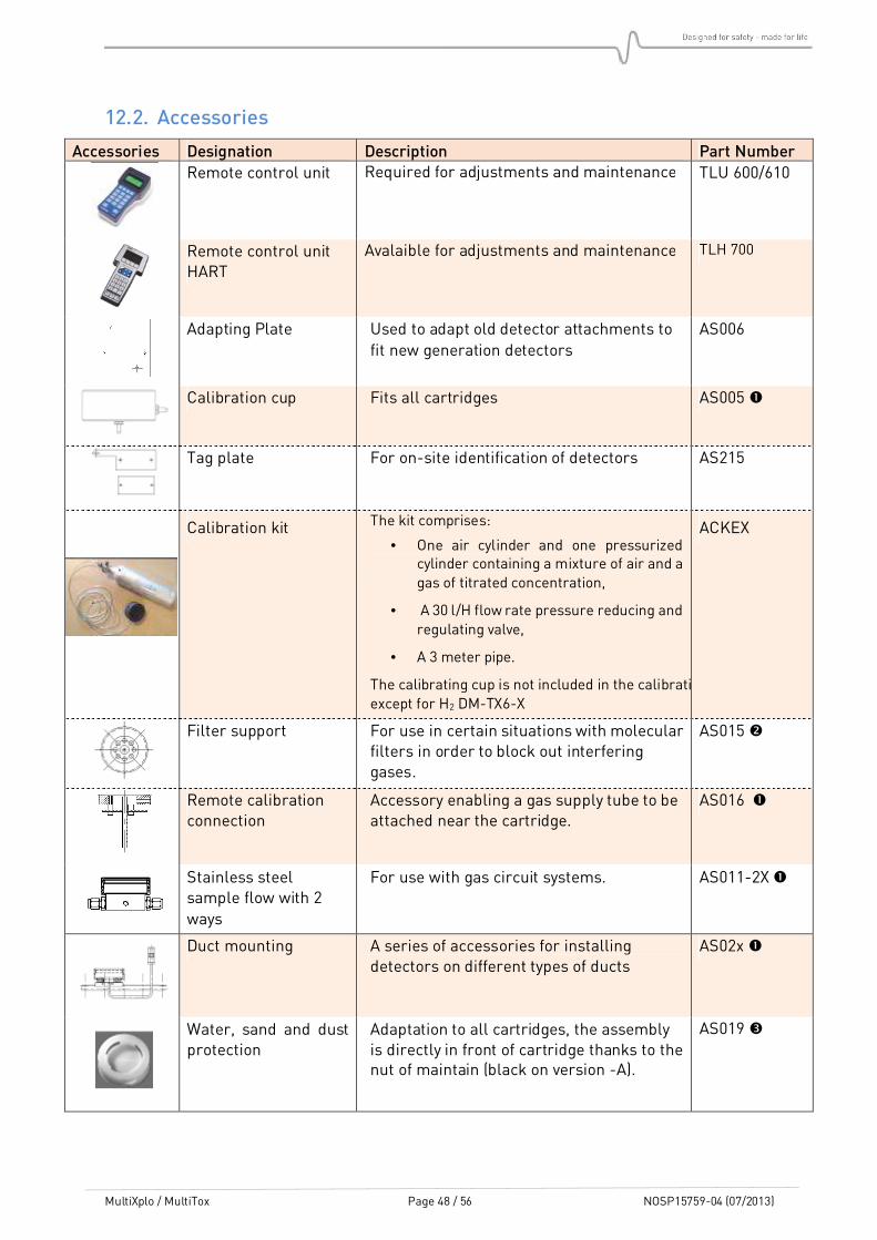
12.2. Accessories
Accessories Designation Description Part Number
Remote control unit Required for adjustments and maintenance TLU 600/610
Remote control unit HART
Avalaible for adjustments and maintenance TLH 700
Adapting Plate Used to adapt old detector attachments to
fit new generation detectors AS006
Calibration cup Fits all cartridges AS005
Tag plate For on-site identification of detectors AS215
Calibration kit The kit comprises:
• One air cylinder and one pressurized cylinder containing a mixture of air and a gas of titrated concentration,
• A 30 l/H flow rate pressure reducing and regulating valve,
• A 3 meter pipe.
The calibrating cup is not included in the calibration kit except for H2 DM-TX6-X
ACKEX
Filter support For use in certain situations with molecular filters in order to block out interfering gases.
AS015
Remote calibration connection
Accessory enabling a gas supply tube to be attached near the cartridge.
AS016
Stainless steel sample flow with 2
ways
For use with gas circuit systems. AS011-2X
Duct mounting A series of accessories for installing detectors on different types of ducts
AS02x
Water, sand and dust protection
Adaptation to all cartridges, the assembly is directly in front of cartridge thanks to the nut of maintain (black on version -A).
AS019

MultiXplo / MultiTox Page 49 / 56 NOSP15759-04 (07/2013)
Detector sensitivity is not modified, response time depend on the flow rate used for injection. A flow rate between 0.5 L/min and 1 L/min should comply with “standard” response time.
Detector sensitivity is not modified; response time can increase depending on the molecular filter used.
Detector sensitivity is not modified, response time (T90) (natural diffusion condition) is increased by 50%.
Suspension cable enclosure/body
Enables to connect the enclosure with the body during the maintenance operations
AS052
Tube mounting
adapter
Enables DM-T#6, DMi-TT6, DG-T#7, DGi-TT7
et GD10P lines to be mounted on a 2 inch to 2.5 inch diameter tube
AS053
Weather protection (wall or tube
mounting)
Dedicated to protect apparatus from sun / rain / snow.
AS056-250
MultiXplo / MultiTox Page 50 / 56 NOSP15759-04 (07/2013)
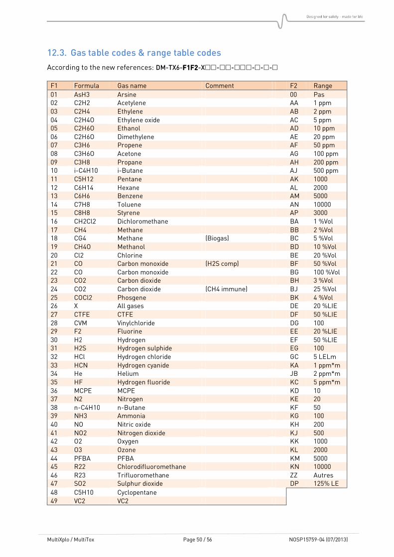
12.3. Gas table codes & range table codes
According to the new references: DM-TX6-F1F2F1F2F1F2F1F2-X-----
F1 Formula Gas name Comment F2 Range
01 AsH3 Arsine 00 Pas 02 C2H2 Acetylene AA 1 ppm 03 C2H4 Ethylene AB 2 ppm 04 C2H4O Ethylene oxide AC 5 ppm 05 C2H6O Ethanol AD 10 ppm 06 C2H6O Dimethylene AE 20 ppm 07 C3H6 Propene AF 50 ppm 08 C3H6O Acetone AG 100 ppm 09 C3H8 Propane AH 200 ppm 10 i-C4H10 i-Butane AJ 500 ppm 11 C5H12 Pentane AK 1000 12 C6H14 Hexane AL 2000 13 C6H6 Benzene AM 5000 14 C7H8 Toluene AN 10000 15 C8H8 Styrene AP 3000 16 CH2Cl2 Dichloromethane BA 1 %Vol 17 CH4 Methane BB 2 %Vol 18 CG4 Methane (Biogas) BC 5 %Vol 19 CH4O Methanol BD 10 %Vol 20 Cl2 Chlorine BE 20 %Vol 21 CO Carbon monoxide (H2S comp) BF 50 %Vol 22 CO Carbon monoxide BG 100 %Vol 23 CO2 Carbon dioxide BH 3 %Vol 24 CO2 Carbon dioxide (CH4 immune) BJ 25 %Vol 25 COCl2 Phosgene BK 4 %Vol 26 X All gases DE 20 %LIE 27 CTFE CTFE DF 50 %LIE 28 CVM Vinylchloride DG 100 29 F2 Fluorine EE 20 %LIE 30 H2 Hydrogen EF 50 %LIE 31 H2S Hydrogen sulphide EG 100 32 HCl Hydrogen chloride GC 5 LELm 33 HCN Hydrogen cyanide KA 1 ppm*m 34 He Helium JB 2 ppm*m 35 HF Hydrogen fluoride KC 5 ppm*m 36 MCPE MCPE KD 10 37 N2 Nitrogen KE 20 38 n-C4H10 n-Butane KF 50 39 NH3 Ammonia KG 100 40 NO Nitric oxide KH 200 41 NO2 Nitrogen dioxide KJ 500 42 O2 Oxygen KK 1000 43 O3 Ozone KL 2000 44 PFBA PFBA KM 5000 45 R22 Chlorodifluoromethane KN 10000 46 R23 Trifluoromethane ZZ Autres 47 SO2 Sulphur dioxide DP 125% LE
48 C5H10 Cyclopentane 49 VC2 VC2

MultiXplo / MultiTox Page 51 / 56 NOSP15759-04 (07/2013)
F1 Formula Gas name Comment 50 D40 White Spirit 51 / Gasoil 52 / Super 95 53 / Super 98 54 / LPG 55 C2H5Cl Ethyl chloride 56 C2H6 Ethane 57 C3H3N Acrylonitrile/Vinyl cyanide 58 C3H6Cl2 Dichloroethane 59 C3H6O Propylene oxide 60 C3H8O Isopropyl alcohol 61 C3H8O Propyl alcohol 62 C4H10O Butanol 63 C4H6 Butadiene 64 C4H8 Butene 65 C4H8O Butanal 66 C4H8O Methyl-ethyl-ketone(MEK) 67 C4H9O2 Ethyl acetate 68 C5H10O Methyl-isopropyl-ketone 69 C5H10O2 Propyl acetate 70 C5H12O Isopentanol 71 C5H8 Isoprene 72 C6H10 D-limonene 73 C6H12 Cyclohexane 74 C6H12 Hexene-1 75 C6H12O2 Butyl acetate 76 C6H16 Heptane 77 C6H4(CH3)2 Xylene 78 C7H12O2 N-butyacrylate 79 C2H4 Ethylene (special) 80 C3H8 Propane 81 CH4 Methane 82 C8H18 Octane 83 CF3-CFH2 R134a 84 / Kerosene 85 C2Cl4 Tetrachloroethene 86 C2H4 Ethylene SA Xs Special combustible gas App SA CS H2 Hydrogen in Argon Complement Argon CU H2 Hydrogen in Azote Complement Azote

MultiXplo / MultiTox Page 52 / 56 NOSP15759-04 (07/2013)
Regarding reference F2 = DG (100% LEL), the following table defines what SIMTRONICS uses of correspondence between %vol and 100% LEL.
F1F1F1F1 Name of compound Formula % vol equivalent to 100% LEL
8 Acetone C3H6O 2.62.62.62.6
2 Acetylene C2H2 2.22.22.22.2
39 Ammonia NH3 16.016.016.016.0
13 Benzene C6H6 1.21.21.21.2
73 Cyclohexane C6H12 1.31.31.31.3
6 Dimethyl ether C2H6O 2.72.72.72.7
56 Ethane C2H6 3.03.03.03.0
5 Ethanol C2H5OH 3.33.33.33.3
3 Ethylene C2H4 2.72.72.72.7
12 N-Hexane C6H14 1.11.11.11.1
10 Isobutane i-C4H10 1.81.81.81.8
17 Methane CH4 5.05.05.05.0
19 Methanol CH3OH 5.55.55.55.5
38 n-Butane C4H10 1.91.91.91.9
11 Pentane C5H12 1.41.41.41.4
9 Propane C3H8 2.22.22.22.2
7 Propylene / propene C3H6 2.02.02.02.0
15 Styrene C8H8 1.11.11.11.1
14 Toluene C7H8 1.21.21.21.2

MultiXplo / MultiTox Page 53 / 56 NOSP15759-04 (07/2013)
13. CONFORMITY CERTIFICATE

MultiXplo / MultiTox Page 54 / 56 NOSP15759-04 (07/2013)
MultiXplo / MultiTox Page 55 / 56 NOSP15759-04 (07/2013)
14. CONTACT DETAILS
You will find an updated list of distributors on our web site:
www.simtronics.eu
Email address for general enquiries: [email protected]
Simtronics SAS 792, av de la Fleuride
BP 11016, 13781 AUBAGNE CEDEX – France Tel: +33 (0) 442 180 600
Simtronics AS Kabelgaten 8, Økern Næringspark PO Box 314, Økern, NO-0511 Oslo, Norway Tel: +47 2264 5055
