norwegian academy of technological sciences 82-7719-051-4 printing: 2005 publisher: norwegian...
TRANSCRIPT

Norwegian Academy of Technological Sciences
Offshore Media Group
Norwegian Petroleum TechnologyA success story

ISBN 82-7719-051-4
Printing: 2005
Publisher: Norwegian Academy of Technological Sciences (NTVA)
in co-operation with Offshore Media Group and INTSOK.
Editor: Helge Keilen
Journalists: Åse Pauline Thirud
Stein Arve Tjelta
Webproducer: Erlend Keilen
Graphic production: Merkur-Trykk AS
Norwegian Academy of Technological Sciences (NTVA) is an
independent academy. The objectives of the academy are to:
– promote research, education and development within the
technological and natural sciences
– stimulate international co-operation within the fields of technology
and related fields
– promote understanding of technology and natural sciences among
authorities and the public to the benefit of the Norwegian society
and industrial progress in Norway.
Offshore Media Group (OMG) is an independent publishing house
specialising in oil and energy. OMG was established in 1982 and
publishes the magazine Offshore & Energy, two daily news services
(www.offshore.no and www.oilport.net) and arranges several petro-
leum and energy based conferences.
The entire content of this book can be downloaded from
www.oilport.net.
No part of this publication may be reproduced in any form, in
electronic retrieval systems or otherwise, without the prior written
permission of the publisher.
Publisher address:
NTVA Lerchendahl gaard, NO-7491
TRONDHEIM, Norway.
Tel: + (47) 73595463 Fax: + (47) 73590830
e-mail: [email protected]
Front page illustration: FMC Technologies.
In many ways, the Norwegian petroleum industry is an eco-nomic and technological fairy tale. In the course of a littlemore than 30 years Norway has developed a petroleumindustry with world class products and solutions. This bookhighlights some of the stories behind this Norwegiansuccess.
A strong Norwegian home market has helped Norwegianindustries to develop technologies in the absolute forefront.In some important areas, like the subsea market, theNorwegian "oil cluster" became world leaders throughcompanies like Vetco, Aker Kværner and FMC Techno-logies. Advanced products for the domestic market, withcost effective and flexible solutions, are also sought after inthe international market place. Norwegian companies arenow involved in some of the world’s foremost projects, fromSakhalin in the east to Brazil in the west and Angola in thesouth.
Norway, with its 4.5 million inhabitants, is a very small countryindeed. As an energy supplier, however, Norway will play anincreasingly important role. This will require an even strongeremphasis on research, competence and technologydevelopment. Today some 75.000 highly qualified peopleare working directly in the Norwegian petroleum industry,where the domestic market is still strong with large fielddevelopments like Snøhvit and Ormen Lange. Norway hasestablished a unique Petroleum Fund, which currently is
passing $ 160 billion, and political leaders in resource richoil countries are looking to Norway for inspiration andguidance.
This book describes some of the best technology storiesthat have emerged from Norwegian research institutions.Financial support, text and illustrations from the companiesand institutions presented in the book have made its publi-cation possible and are gratefully acknowledged. An editorialcommittee has been responsible for producing the bookunder the chairmanship of Research Director Ole Lindefjeldof ConocoPhillips, who once demonstrated a multipliereffect of at least 15 times the amount of money that hiscompany had invested in research and development inNorway. The committee hopes that telling these stories ofNorwegian technology will demonstrate that research reallydoes pay. The editorial committee has consisted of:
Ole Lindefjeld (chair) ConocoPhillipsHelge Keilen (editor) Offshore Media GroupKari Druglimo The Research Council of NorwaySiri Helle Friedemann The Research Council of NorwayLiv Lunde IFE Institute for Energy TechnologyDavid Lysne SINTEF Petroleum ResearchKjell Markman RF Rogland ResearchGrethe Schei SINTEF Petroleum ResearchKnut Åm Norwegian Academy of
Technological Sciences (NTVA)
Preface

Contents
Foreword by Thorhild Widvey, Minister of Petroleum and Energy . . . . . . . . . . . . . . . . . . . . . . . . . . . . . . . . . . . . . . . . . . . 9
Competitive technological capabilities, INTSOK . . . . . . . . . . . . . . . . . . . . . . . . . . . . . . . . . . . . . . . . . . . . . . . . . . . . . . . . . . . . 11
MAJOR FIELD DEVELOPMENT PROJECTSValue creator on the Norwegian continental shelf through innovative thinking, ConocoPhillips . . . . . . . . . 14
«Invisible» Technology. From Tommeliten to Snøhvit, Statoil . . . . . . . . . . . . . . . . . . . . . . . . . . . . . . . . . . . . . . . . . . . . 19
Europe’s largest offshore development on track, Hydro . . . . . . . . . . . . . . . . . . . . . . . . . . . . . . . . . . . . . . . . . . . . . . . . 25
Troll Story – A story of ingenuity, Hydro . . . . . . . . . . . . . . . . . . . . . . . . . . . . . . . . . . . . . . . . . . . . . . . . . . . . . . . . . . . . . . . . . 26
EXPLORATIONResearch enters the age of oil, SINTEF . . . . . . . . . . . . . . . . . . . . . . . . . . . . . . . . . . . . . . . . . . . . . . . . . . . . . . . . . . . . . . . . 28
Revolutionary exploration methods, NGI . . . . . . . . . . . . . . . . . . . . . . . . . . . . . . . . . . . . . . . . . . . . . . . . . . . . . . . . . . . . . . . . 29
Untethered raven, Kongsberg Maritime . . . . . . . . . . . . . . . . . . . . . . . . . . . . . . . . . . . . . . . . . . . . . . . . . . . . . . . . . . . . . . . . . 31
SEMI 3D improves discovery rates, SINTEF . . . . . . . . . . . . . . . . . . . . . . . . . . . . . . . . . . . . . . . . . . . . . . . . . . . . . . . . . . . . 32
Temperature – the most important unknown factor in exploration, RF – Rogaland Research . . . . . . . . . . . 33
New geological knowledge creates more efficient oil and gas exploration, Statoil . . . . . . . . . . . . . . . . . . . . 34
DRILLING AND RESERVOIRFull-scale Drilling and Well Technology Test Facility, RF - Rogaland Research . . . . . . . . . . . . . . . . . . . . . . . . . 36
Control of Well Pressure, RF - Rogaland Research . . . . . . . . . . . . . . . . . . . . . . . . . . . . . . . . . . . . . . . . . . . . . . . . . . . . . 37
Three-dimensional success from the seabed, CMR . . . . . . . . . . . . . . . . . . . . . . . . . . . . . . . . . . . . . . . . . . . . . . . . . . . . 38
Innovations on Troll, Baker Hughes Inc. . . . . . . . . . . . . . . . . . . . . . . . . . . . . . . . . . . . . . . . . . . . . . . . . . . . . . . . . . . . . . . . . . 39
Good sand control gave increased recovery and increased production, SINTEF . . . . . . . . . . . . . . . . . . . . . . . 40
Enhanced recovery with tracer technology in reservoirs, IFE . . . . . . . . . . . . . . . . . . . . . . . . . . . . . . . . . . . . . . . . . . . 41
Foam improves recovery rates on Snorre, SINTEF . . . . . . . . . . . . . . . . . . . . . . . . . . . . . . . . . . . . . . . . . . . . . . . . . . . . . . 42
With time as the fourth dimension. Schlumberger . . . . . . . . . . . . . . . . . . . . . . . . . . . . . . . . . . . . . . . . . . . . . . . . . . . . . . 43
FIELD DEVELOPMENTGigantic Offshore Structures, SINTEF . . . . . . . . . . . . . . . . . . . . . . . . . . . . . . . . . . . . . . . . . . . . . . . . . . . . . . . . . . . . . . . . . . 46
Skirt foundations and suction anchors worldwide, NGI . . . . . . . . . . . . . . . . . . . . . . . . . . . . . . . . . . . . . . . . . . . . . . . . . 47
Renaissance for concrete expertise from the North Sea, Aker Kværner . . . . . . . . . . . . . . . . . . . . . . . . . . . . . . . . 48
The SESAM software platform, DNV . . . . . . . . . . . . . . . . . . . . . . . . . . . . . . . . . . . . . . . . . . . . . . . . . . . . . . . . . . . . . . . . . . . . 50
The world’s largest ocean basin, SINTEF . . . . . . . . . . . . . . . . . . . . . . . . . . . . . . . . . . . . . . . . . . . . . . . . . . . . . . . . . . . . . . . 52
Subsea risk of landslides, NGI . . . . . . . . . . . . . . . . . . . . . . . . . . . . . . . . . . . . . . . . . . . . . . . . . . . . . . . . . . . . . . . . . . . . . . . . . 53
Monitoring offshore and on land, NGI . . . . . . . . . . . . . . . . . . . . . . . . . . . . . . . . . . . . . . . . . . . . . . . . . . . . . . . . . . . . . . . . . . 54
Subsea innovation with a boost, Aker Kværner . . . . . . . . . . . . . . . . . . . . . . . . . . . . . . . . . . . . . . . . . . . . . . . . . . . . . . . . . 55
From hand-drawn sketch to technological success, FMC Technologies . . . . . . . . . . . . . . . . . . . . . . . . . . . . . . . . 56
Cost-effective subsea development, Vetco . . . . . . . . . . . . . . . . . . . . . . . . . . . . . . . . . . . . . . . . . . . . . . . . . . . . . . . . . . . . 57
SIMLA facilitated Ormen Lange subsea to shore, SINTEF . . . . . . . . . . . . . . . . . . . . . . . . . . . . . . . . . . . . . . . . . . . . . . 59
Technical expertise with focus on safety, DNV . . . . . . . . . . . . . . . . . . . . . . . . . . . . . . . . . . . . . . . . . . . . . . . . . . . . . . . . . . 60
OLGA enables field development without platforms, IFE and SINTEF . . . . . . . . . . . . . . . . . . . . . . . . . . . . . . . . . . 61
Technology moving from the platform to the sea bed, FMC Technologies . . . . . . . . . . . . . . . . . . . . . . . . . . . . . 62
The future design tool for advanced well-flow transport, SINTEF . . . . . . . . . . . . . . . . . . . . . . . . . . . . . . . . . . . . . . . 64
LNGLNG-transport, DNV . . . . . . . . . . . . . . . . . . . . . . . . . . . . . . . . . . . . . . . . . . . . . . . . . . . . . . . . . . . . . . . . . . . . . . . . . . . . . . . . . . . . 66
LNG technology made Snøhvit possible, SINTEF . . . . . . . . . . . . . . . . . . . . . . . . . . . . . . . . . . . . . . . . . . . . . . . . . . . . . . 67
Norwegian loading technology may change the world’s LNG imports, Remora . . . . . . . . . . . . . . . . . . . . . . . . 68
OPERATIONSBetter safety and optimal operation, IFE . . . . . . . . . . . . . . . . . . . . . . . . . . . . . . . . . . . . . . . . . . . . . . . . . . . . . . . . . . . . . . . . 70
A quantum leap in the development of seabed wells, FMC Technologies . . . . . . . . . . . . . . . . . . . . . . . . . . . . . 71
Inventions which provide cleaner emissions to marine environments, RF - Rogaland Research . . . . . . . 72
Improvements for safety, ABB . . . . . . . . . . . . . . . . . . . . . . . . . . . . . . . . . . . . . . . . . . . . . . . . . . . . . . . . . . . . . . . . . . . . . . . . . . 73
Offshore reliability data, SINTEF . . . . . . . . . . . . . . . . . . . . . . . . . . . . . . . . . . . . . . . . . . . . . . . . . . . . . . . . . . . . . . . . . . . . . . . . 74
Multiphase technology, CMR . . . . . . . . . . . . . . . . . . . . . . . . . . . . . . . . . . . . . . . . . . . . . . . . . . . . . . . . . . . . . . . . . . . . . . . . . . . 75
Slug control, ABB . . . . . . . . . . . . . . . . . . . . . . . . . . . . . . . . . . . . . . . . . . . . . . . . . . . . . . . . . . . . . . . . . . . . . . . . . . . . . . . . . . . . . . . 76
VIEC has increased the production of Troll C, Vetco . . . . . . . . . . . . . . . . . . . . . . . . . . . . . . . . . . . . . . . . . . . . . . . . . . . . 77
pH stabilization for corrosion control, IFE . . . . . . . . . . . . . . . . . . . . . . . . . . . . . . . . . . . . . . . . . . . . . . . . . . . . . . . . . . . . . . . 78
HVDC on Troll, ABB . . . . . . . . . . . . . . . . . . . . . . . . . . . . . . . . . . . . . . . . . . . . . . . . . . . . . . . . . . . . . . . . . . . . . . . . . . . . . . . . . . . . . 79
Biological effect methods: Bio-markers, RF - Rogaland Research . . . . . . . . . . . . . . . . . . . . . . . . . . . . . . . . . . . . . . 80
DECOMMISSIONINGDecommissioning of the Frigg platforms, Aker Kværner . . . . . . . . . . . . . . . . . . . . . . . . . . . . . . . . . . . . . . . . . . . . . . . . 82
THE FUTUREPETROMAKS – A large strategic petroleum R&D program, The Research Council of Norway . . . . . . . . . . 84
Oil and gas in the 21st century, OG21 . . . . . . . . . . . . . . . . . . . . . . . . . . . . . . . . . . . . . . . . . . . . . . . . . . . . . . . . . . . . . . . . . 86
From technology to value, DEMO 2000 . . . . . . . . . . . . . . . . . . . . . . . . . . . . . . . . . . . . . . . . . . . . . . . . . . . . . . . . . . . . . . . . 87
Acknowledgements . . . . . . . . . . . . . . . . . . . . . . . . . . . . . . . . . . . . . . . . . . . . . . . . . . . . . . . . . . . . . . . . . . . . . . . . . . . . . . . . . . . . . 89

The oil and gas industry is an importantpart of Norway’s national economy,and it has made important contributionsto the development of the Norwegianwelfare state. One of several factorsunderlying the creation of value thathas taken place during the epoch ofNorwegian oil has been the efforts putinto petroleum-oriented research andtechnology development. Togetherwith other facets of our petroleum policyand industrial investment in this sector,petroleum research has been animportant part of the development ofNorway as an oil-producing country,and in this way has contributed to layingthe foundations for the long-termdevelopment of this branch of industry.
This book bears clear witness to the role played byNorwegian research centres in the development of theNorwegian petroleum sector in close collaboration withother actors in this industry. ConocoPhillips has taken avery praiseworthy initiative to produce this book incollaboration with Norwegian research institutes and theother parties involved.
The expertise which has been built up in the course of timeis in many ways an invisible but decisive factor in theNorwegian petroleum sector. A wide range of examplesoffer us a picture full of insights into how Norway, as apetroleum nation, has managed to develop leading-edgeexpertise in the field of petroleum technology. The resultsillustrated in this volume provide valuable documentation ofthe important technological advances that have been madein one of the core chapters of the recent industrial historyof Norway.
The petroleum sector is an industrywith a future. To date, only one third ofthe oil and gas resources on theNorwegian shelf have been pro-duced. Technological developmentson the Norwegian shelf provide goodevidence of the potential returns thatlong-term investment in researchoffer the state and industry, evidencewhich emerges clearly from thehistorical material presented in thisbook. Investment in research andtechnology is an important tool forrealising the possibilities and chal-lenges that face us as a nation on thecontinental shelf and for ensuring thatindustry is capable of maintaining itsinternational competitiveness. As
Minister of Petroleum and Energy I lay great weight on thisaspect, not least in how I prioritise the authorities’ owninvestment in research. Norway has the possibility of furtherdeveloping the competence needed to satisfy the demandfor advances in research and technology that are essentialif the Norwegian petroleum industry is to be able to lookforward to successful development in the future. Theestablishment of a national strategy in petroleum-orientedtechnology and research, OG21 (Oil and Gas in the 21stCentury), has been important as a tool for ensuring that weinvest in relevant areas of R&D for the sake of the future.
I strongly believe that Norwegian research will continue towork at the leading edge in core areas of the oil and gassector. That they should do so will be of decisive importancefor the continued creation of value on the Norwegiancontinental shelf, and for our prospects on the internationalscene.
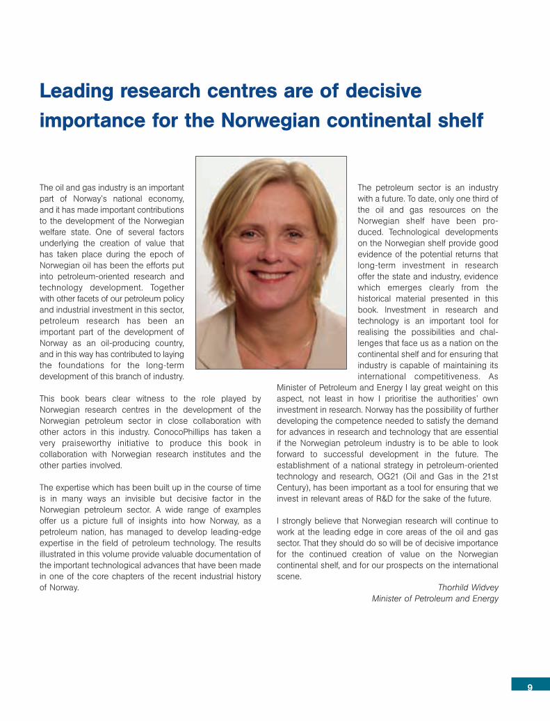
Thorhild WidveyMinister of Petroleum and Energy
Leading research centres are of decisive importance for the Norwegian continental shelf
9

11
INTSOK – Norwegian Oil and Gas Partners
The Norwegian Continental Shelf (NCS) has for30 years been a laboratory for developing newcost effective solutions and technologies.Research and development have been impor-tant in order to reduce costs, increase recoveryand secure sound environmental solutions. Themajor factors in building industrial competiti-veness in the Norwegian oil and gas sector arethe giant fields and pioneering technologicalprojects, the world class maritime knowledge,innovative and risk willing firms, large R&Dinvestments and strong emphasis on qualityand price competition.
The partnering between the oil companies, Norwegian aswell as international, the supply industry, the research insti-tutions and academia has made Norway one of the bestenvironments for technological developments. Access tosuperb engineers and strong project teams has enabled
the Norwegian oil industry to deliver on time, quality andcost. The operators on the NCS have also been morewilling to use new technological solutions than operators inmost other offshore provinces.
Technological success stories Drilling technology has made it possible to develop fieldslike Troll Oil – a large thin oil zone under a major gas field.15 years ago that was seen as uneconomic, but Hydro hadthe vision and the ambition to go ahead. Troll oil is nowproducing from 35 branched wells and a further 15 newbranched wells are planned.
Technology has been fundamental for the progress seen inreservoir management and enhanced recovery factors. Theaverage recovery factor on the Norwegian Continental Shelfis some 45 per cent and the focus is on increasing theaverage recovery factor to more than 50 percent. In someof the maturing fields up to 70 percent of oil in place will beproduced. Every percentage point growth in recovery adds30 billion dollars of value to the industry and society.
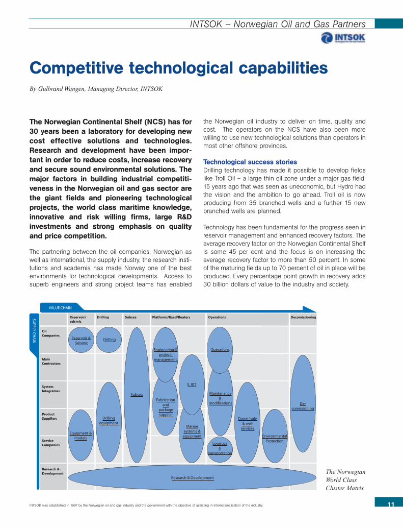
Competitive technological capabilitiesBy Gulbrand Wangen, Managing Director, INTSOK
OilCompanies
MainContractors
SystemIntegrators
ProductSuppliers
ServiceCompanies
Research &Development
VALUE CHAIN
SUPPLY
CH
AIN
Reservoir/seismic
SubseaDrilling Platforms/fixed/floaters Operations Decomissioning
Reservoir & Seismic
Drilling
Drillingequipment
Equipment &models
SubseaFabrication
andpackagesupplier
Marinesystems &
equipment
Maintenance&
modifications
Down-hole& well
services
EnvironmentalProtection
De-comissioning
Logistics&
transportation
Research & Development
OperationsEngineering &project-
management
E, I&T
INTSOK was established in 1997 by the Norwegian oil and gas industry and the government with the objective of assisting in internationalisation of the industry.
The NorwegianWorld ClassCluster Matrix
Technology has also allowed companies to meet ever morestringent environmental requirements, such as no harmfuldischarges to sea and CO2 storage in subsea reservoirs,like on the Statoil-operated Sleipner field in the NorwegianNorth Sea.
Floating production and extensive use of subsea technologyhas revolutionised the way projects are developed andhave made new development solutions far more cost effective.
A cluster at the leading edge A strong domestic market has been and still is the basis fortechnological development and expansion into the globalmarkets. INTSOK’s mapping of the Norwegian petroleumcluster documents that the Norwegian oil industry hasdeveloped 16 competitive, leading edge supply chainswhich enable the companies to win orders internationally.
Technology developed and applied in Norway has alreadycontributed to major export earnings in international pro-jects, and the trend is towards more focus on internationalopportunities.
Norwegian companies are involved from arctic conditions inSakhalin, North Caspian and the Barents Sea to deepwaterin West Africa, Brazil and Gulf of Mexico. The large projectstend to get the big headlines, but many good ideas areconverted to advanced products and services. Most of theINTSOK partners are small and medium-sized companieswith an annual turn-over within the oil and gas sector below10 million dollars. Many of them are supplying a wide rangeof cost effective and flexible quality products and servicesto the global market.
Two major concrete gravity base substructures are built forSakhalin Energy, operated by Shell. One is the Piltun offs-hore platform, the other is the Lunskoye platform.
The two substructures are amongst the biggest structuresever built in Russia and the varied geometry of the legsputs them amongst the most complex concrete slipforming jobs ever undertaken. They are the first structuresof their type to be built in the country, with a Russiancontent of some 85% and a workforce of some 2,000Russians involved in their construction.
The developments of the deepwater offshore fields off thecoast of Angola are another example. Three Norwegianbased companies, FMC Technologies, Aker Kvaerner andVetco International have secured 75-80 per cent of the sub-sea market based on the technologies and competencesdeveloped on the NCS.
Norwegian research institutions are rapidly expanding theirbusiness outside Norway.
SINTEF, a Norwegian research institution with 1800employees, has some 30 percent of its revenues fromoutside Norway. The institution has delivered several fielddevelopment plans in Iran and is also involved in an R&Dproject on gas based Increased Oil Recovery (IOR) in frac-tured carbonate reservoirs in the country. The SINTEFGroup offers R&D services along the whole hydrocarbonchain, from source rock to end user. The Group providesleading edge tools and solutions within basin modelling,seismic processing, rock mechanics, flow assurance, CO2deposition, FAWAG (foam assisted water alternating gasinjection), LNG, GTL (Gas to liquids), floating productionfacilities, pipelines, moorings, safety and reliability analysisand subsea power distribution. SINTEF operates the largestmultiphase flow laboratory and offshore basin laboratory inthe world.
The Institute for Energy Technology (IFE) and SINTEF havedeveloped OLGA, a dynamic software tool for engineeringand operation of multiphase production systems. OLGA2000, marketed by Scandpower Petroleum Technology,has become the market-leading simulator for transientmultiphase flow of oil, water and gas in wells and pipelineswith process equipment and is used by 100 companiesworld wide. IFE, the Institute for Energy Technology, hasbecome an internationally recognized centre in the field ofinternal corrosion of oil and gas pipelines as a result of aseries of joint industry projects. IFE’s tracer technology isalso widely used internationally. The institution carries forexample out tracer services on five fields in Venezuela.
RF-Rogaland Research has the world's most advanced full-scale Drilling and Well Centre, with testing sites, flow loopsand related laboratories. The research group offers compe-tence in development of environmentally acceptable tech-nologies, geological modelling, reservoir evaluation, drilling,well completion and IOR.
The Norwegian Geotechnical Institute (NGI) has a worldleading competence within geotechnics, engineering geo-logy, environmental geotechnology combined with expertisewithin material properties, modelling and analysis.
Christian Michelsen Research (CMR) has led the develop-ment of a sophisticated software based on the VirtualReality Technology which allow us for three dimensionalexploration of complex geological structures and data. Thistechnology is today marketed by Schlumberger.
12
INTSOK – Norwegian Oil and Gas Partners

In 1969, the discovery of oil and gas on Ekofiskturned Norway into a petroleum nation. In thecourse of 40 years as a participant in thisindustry, ConocoPhillips has gone beyond thelimits of what has been regarded as techno-logically possible.
The discovery of the Ekofisk reservoir in a chalk formationas the North Sea’s first commercial oilfield, the start ofproduction 18 months after the discovery, the constructionof the Ekofisk Tank as the first concrete oil and gas platformin the world, the laying of what was then the longest sub-sea pipelines with their compressor platforms, the jackingup of six steel platforms by six metres on Ekofisk in 1987,water injection into the chalk reservoir, considerably increasingthe recovery rate, the development of the Heidrun field withthe world’s first concrete tension leg platform (TLP) – withoutstorage capacity and carbon fibre risers for great depths.These are just some of the highlights from the story – at thesame time as ConocoPhillips is a driving force behind theoperating model of the future, and is adopting e-operatingmethods capable of supporting drilling and production insuch distant parts of the world as Vietnam and Alaska.
This enormous development has taken place in collabo-ration between internal and external professionals andresearchers, owners in the production licenses, the serviceindustry, vendors and the Norwegian authorities. Conoco-Phillips has challenged – and been challenged by – thesegroupings to find solutions to problems that have appearedeither difficult or on the verge of the impossible. Together,however, we have arrived at solutions that we can all beproud of, and which have found application not only on theNorwegian continental shelf, but have been brought byConocoPhillips out into a wider world. The company isoperating in more than 40 countries and has helped tointroduce Norwegian technology and Norwegian companiesto the whole world.
EkofiskIn what follows, we will take the development of the greaterEkofisk area as a good example of what we have achievedvia collaboration with the research sector, the service industry,vendors, the authorities and co-venturers.
The creation of value from Ekofisk has undergone an enor-mous development in the period between 1971 and 2004.
The recovery rate from the Ekofisk chalk field has risen froman estimated 17 percent in 1971 to an estimated 46 percentin 2004. Values of 200 billion dollars have been generateduntil 2004.
When the Ekofisk reservoir was demonstrated as the firstmajor oil reserve in the North Sea in 1969, a number offundamental questions were raised. Is stable productionover a long period of time possible from such a chalk reser-voir? Are the environmental conditions in the middle of theNorth Sea, one of the most hostile seas in the world, suchthat it would be possible to build safe platforms and infra-structures for profitable oil and gas activities?
35 years later we can be certain that the answers to thesequestions are positive, and that the geologist who promisedto drink all the oil that was produced from the chalk field,didn’t know what he was talking about.
Half of the world’s petroleum resources are to be found inchalk reservoirs, while sandstone is often a better reservoirrock for oil and gas. Sandstone is often more porous andhas better production properties, gives up its oil and gasmore willingly, and offers a relatively high recovery rate.
Value creator on the Norwegian continental By Stig S. Kvendseth
14
ConocoPhillips
The greater Ekofisk area currently consists of 29 platforms,some 1100 km internal pipelines and two export pipelines –one for crude oil and NGL to Teesside in the UK and one fordry gas to Emden in Germany. Of eight fields in the area, fourhave already been closed in and 11 platforms are due to beremoved by 2013. After more than 30 years of production,Ekofisk is one of the most productive petroleum fields on theNorwegian continental shelf.
1. Phillips Petroleum Company and Conoco Inc. merged in 2002, becoming ConocoPhillips. Both of the former companies had been active on the Norwegian continental shelf since the start of the offshore industry. In what follows,the company is referred to as ConocoPhillips, even though Phillips and Conoco were separate companies at the time of the events described here.
15
ConocoPhillips
Chalk is more dense and yields its oil and gas more slowlyand with a lower recovery rate, to put it in simple terms.There are a number of factors that complicate this somewhatschematic presentation, but let us make it as simple asthat. When the Ekofisk field was discovered in an enor-mous chalk reservoir in 1969, it was Holy Writ that fields ofthis type had low recovery rates, and that production wouldoffer a large number of challenges.
Test productionEver since the start of production in 1971 this was plannedfor. Production started in the form of test production from amodified jack-up rig – "Gulftide". History was being madeeven at this early stage – a jack-up drilling rig was rebuiltfor production from four subsea wells. The wells that werebrought into production were exploration and appraisalwells. The crude oil production of up to 40,000 barrels aday went straight into tankers via loading buoys. This wasdone only 18 months after the Ekofisk field had beendiscovered!
When it turned out that the four wells were sometimesproducing 10,000 barrels a day each, and that productionwas stable, the production properties of the reservoir hadbeen demonstrated. Development could continue on thebasis of permanent platforms. In the course of the 70s, theEkofisk field was developed, as were the six fields knownas Cod, West Ekofisk, Tor, Albuskjell, Eldfisk and Edda.Apart from Cod, all the reservoirs were in chalk formations.The pipelne for landing crude oil and NGL to Teesside inthe UK was installed, while a gas pipeline was installed toEmden in Germany. The 34 inch, 356 kilometre-long pipelineto Teesside was the first of its type, with two pumping plat-forms to maintain pressure, and a capacity of one millionbarrels a day. The gas pipeline to Emden was even longerat 440 km, and larger, with a diameter of 36 inches, and italso had two compressor platforms along its length tomaintain the pressure. The capacity of this pipeline wasabout two billion cubic feet a day.
Gas injectionIn the Mid-East, where there are many major carbonatereservoirs, large volumes of gas were injected in order tomaintain reservoir pressure and thus increase recoveryrates. On Ekofisk, the gas was injected before the gas pipe-line to Emden was opened in 1977. The Ekofisk ownerscontracted the sale of the gas to a European consortiumled by Ruhrgas; the first ever Norwegian sales contract for
gas. After 1977, about one third of the gas producedcontinued to be injected – partly as pressure support andpartly in order to regulate deliveries according to demand.
Water injectionThe first laboratory test of water injection as a means ofpressure support for enhanced recovery started in 1979.The production history of Ekofisk. These laboratory tests did
shelf through innovative thinking
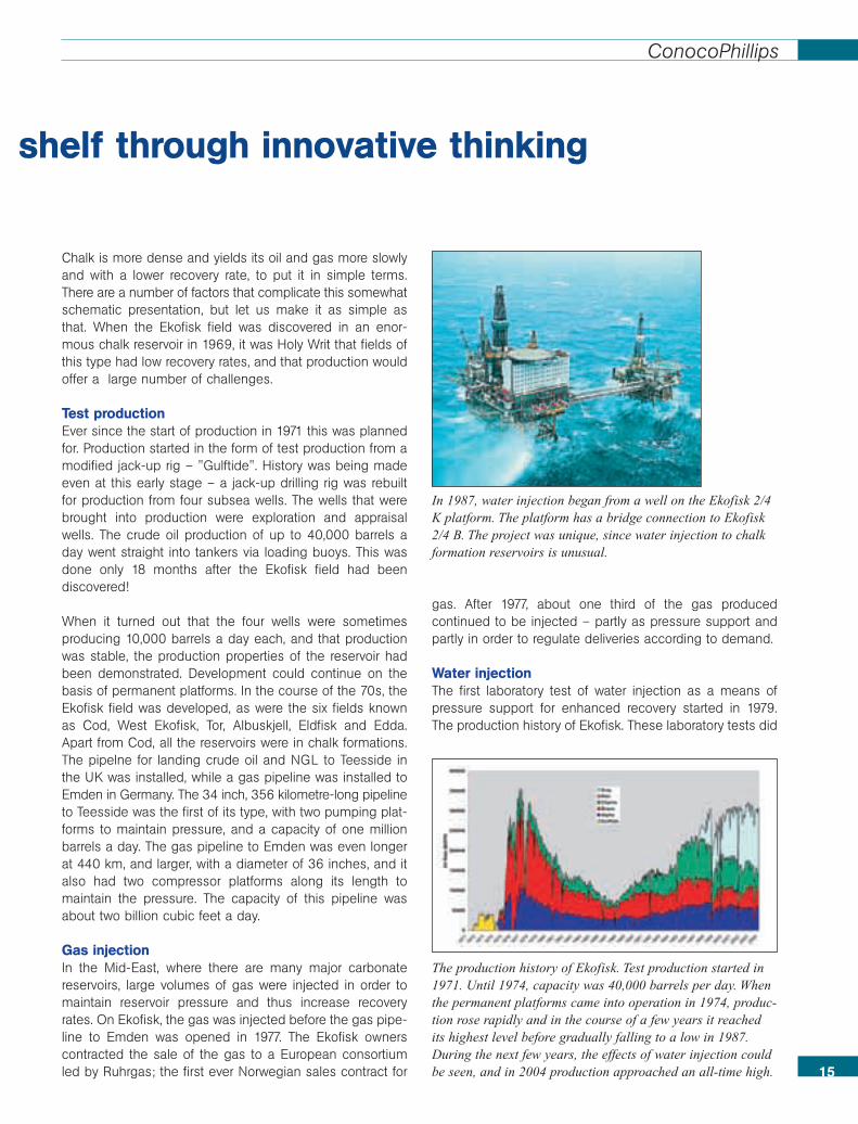
In 1987, water injection began from a well on the Ekofisk 2/4K platform. The platform has a bridge connection to Ekofisk2/4 B. The project was unique, since water injection to chalkformation reservoirs is unusual.
The production history of Ekofisk. Test production started in1971. Until 1974, capacity was 40,000 barrels per day. Whenthe permanent platforms came into operation in 1974, produc-tion rose rapidly and in the course of a few years it reachedits highest level before gradually falling to a low in 1987.During the next few years, the effects of water injection couldbe seen, and in 2004 production approached an all-time high.
not provide unambiguous answers, but the first tentativeplans for a possible water injection project for the Ekofiskfield were drawn up. The authorities, led by the NorwegianPetroleum Directorate, were a driving force at this point intime, in addition to the company’s own experts. In 1981,test of water injection from a well on the Ekofisk 2/4 B plat-form began. Water was injected into the lower part of thereservoir - the Tor formation. The laboratory tests had shownthat it was the chalk in this part of the reservoir that had thegreatest water-absorbing capacity, and was thus mostcapable of displacing the oil towards the production well.The core of the problems concerning the effects of water inchalk reservoirs is the ability of the chalk to absorb water.Furthermore, can the water damage the chalk and thusboth help to reduce production capacity and acidify the oiland gas? The risks are great!
CollaborationDuring autumn 1982 sufficient data were available toconfirm that water injection appeared to be only marginallyprofitable. As the price of oil was also showing some weak-ness in January 1983, the economic advantages of waterinjection were disappearing, at least on the basis of com-pany economics criteria. The Ekofisk owners entered intonegotiations with the Norwegian authorities with the aim ofimproving the general conditions for carrying out theproject, which had positive social economic effects. After
long negotiations the parties came to agreement; theEkofisk water injection project was given improved depreci-ation rates and the project started up.
Gradual developmentA separate water injection platform, Ekofisk 2/4 K, was builtand installed in the northern part of the Ekofisk field. Itstarted water injection in 1987 in the lower part of the Torformation. This first phase of the project provided waterinjection for about a third of the Ekofisk reservoir, with about350,000 barrels of water being injected every day. In thecourse of the 90s, the water injection programme wasextended several times, with the result that by 2004 itcovered the whole Ekofisk reservoir, with an injection capa-city of nearly a million barrels of purified seawater a day.The Ekofisk field has turned out to be unique, and the frac-tured chalk absorbs water particularly well. When producti-on started in 1971, the reservoir pressure was 7000 psi. In1987, before the start of water injection, it had fallen to3,500 psi, while by 2004 it was 5,500 psi. In the course of2004, production has set new records, after 33 years ofproduction. In 2004, Ekofisk, along with Troll, were the big-gest petroleum producers on the Norwegian continentalshelf! Water injection is not the only reason for this, but it isthe most important factor besides developments in welltechnology, particularly horizontal wells, and the experienceand competence developed in dealing with the reservoir byConocoPhillips, the operator.
Continuous process of researchHow has all this been possible?The answer is complex, and it is a combination of a numberof factors. What these factors have in common is an itera-tive process involving experts on the operational side andscientists, as well as collaboration among the owners, theNorwegian authorities, research institutions and the supplyindustry.
As early as 1980, the Joint ChalkResearch Project was launched byNorwegian and Danish authorities incollaboration with the owners to chalkfields in the North Sea. The projectfocused on the challenges offered bychalk formation reservoirs. What wasspecial, in an international contexttoo, was that the authorities andindustrial companies joined forces ina task of this sort. This area of rese-arch has been continued, and wasstill under way in 2004.
Since the mid-80s, the Ekofiskowners have been supporting studiesat the University of Bergen aimed at16
ConocoPhillips
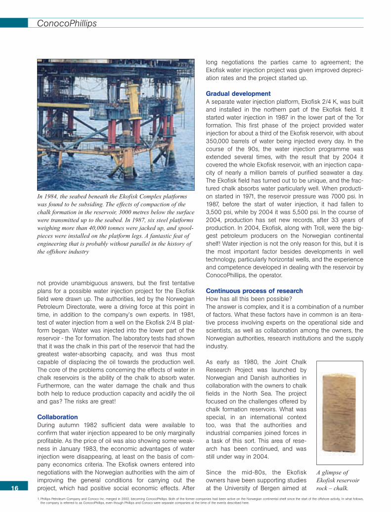
In 1984, the seabed beneath the Ekofisk Complex platformswas found to be subsiding. The effects of compaction of thechalk formation in the reservoir, 3000 metres below the surfacewere transmitted up to the seabed. In 1987, six steel platformsweighing more than 40,000 tonnes were jacked up, and spool-pieces were installed on the platform legs. A fantastic feat ofengineering that is probably without parallel in the history ofthe offshore industry
A glimpse ofEkofisk reservoirrock – chalk.
1. Phillips Petroleum Company and Conoco Inc. merged in 2002, becoming ConocoPhillips. Both of the former companies had been active on the Norwegian continental shelf since the start of the offshore activity. In what follows,the company is referred to as ConocoPhillips, even though Phillips and Conoco were separate companies at the time of the events described here.

building up a detailed understanding of the fundamentalmechanisms involved in water injection in fractured lime-stone formations. A number of master’s and doctoralstudents have taken part in this programme. The RUTH andSPOR research programmes have taken place in collabo-ration with The Research Council of Norway. Three-phaseflow in chalk and sandstone formations related to the injec-tion of gas and water, has been another area of study. InNorway, SINTEF, Rogaland Research and Reslab haveparticipated in this programme.
Another project has looked at air injection for enhanced oilrecovery. ThermicAiroil was partly financed by the EU andboth national and international research institutions wereparticipants.
Corec is another project aimed to improve our understan-ding of the potential for enhanced recovery from the fieldsin the Ekofisk area. This is a collaborative project involvingRogaland Research and the University of Stavanger. Inaddition to financial backing, the Ekofisk owners aresupplying the project with project data, priorities and, notleast, practical experience.
ConocoPhillips developed the Heidrun field while Statoiltook over operating responsibility once the platform hadbeen installed. ConocoPhillips had previously built tensionlegplatforms in steel. Because of the great water depth invol-
ved, it was necessary to reduce the weight to below that oftraditional platforms, and it was decided to use concreteinstead of steel. Advance loading technology was alsointroduced on Heidrun, and for the first time on aNorwegian field, a loading system without storage on thefield was adopted.Process of innovation
17
The social accounts for the greater Ekofisk area show that bythe end of 2004 it had created values of 200 billion dollars.Of this total, about 70 billion had gone to goods and services,about 8 billion to salaries, etc., and 4 billion to lenders. Theowners are left with about 20 billion, while the Norwegianstate has taken more than half in taxes and duties; approxi-mately 100 billion dollars.
Gods and services444 billion nok
Taxes and royalty 626 billion nok
Employees 50 billion nokLenders 24 billion nok
Owners 132 billion nok
Total value created fromthe Greater Ekofisk Area1969 – 2004:1260 billion 2004-Norwegiankroner (nok)
Social account 1969-2004 for Ekofisk
ConocoPhillips
In 2004, the Ekofisk Complex consisted of 11 platformslinked by walkways or bridges. The 12th platform is beingbuilt, and will be installed on the field in 2005.
In 1990, water injection also started on the Eldfisk field.Although this field lies within the greater Ekofisk area, itschalk reservoir is different from the Ekofisk field, which isabout 20 km north of Eldfisk. It remains to be seen whet-her water injection will be as effective here as it has beenin the Ekofisk reservoir. In 90 percent of chalk reservoirsaround the world, water will not force its way into thisporous chalk and displace the oil.
ConocoPhillips has been, and still is, a pioneer in theNorwegian petroleum industry. The company has helped tobuild up expertise in the authorities, research institutes, thesupply industry and industry in general. We estimate thatwe have invested some 250 million dollars in projects atinstitutes, and we have put our best experts at the disposalof the sector in order to ensure that technology is reallytransferred in practice. This is what we have done, it is whatwe are doing today and it is what we will continue to do inthe future in order to meet the many major challenges thatface this industry in Norway. A continuing process of rese-arch, as well as collaboration between scientists and theoperational sector, is the basis of successful production ofoil and gas from the Norwegian continental shelf.
18
ConocoPhillips
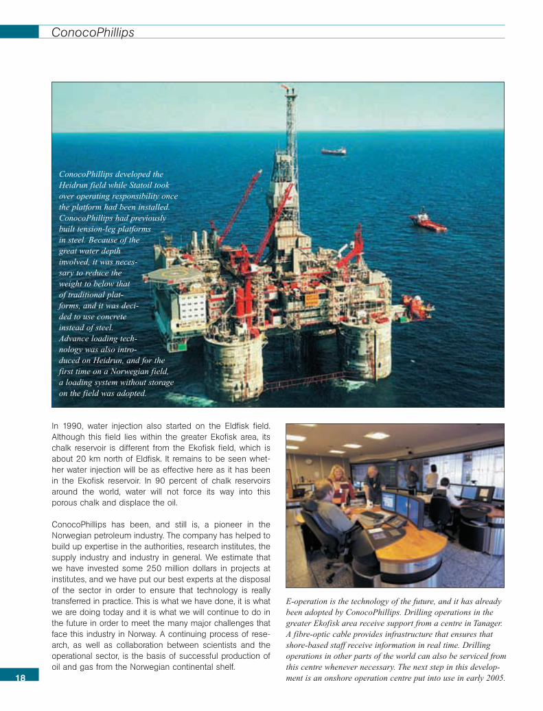
E-operation is the technology of the future, and it has alreadybeen adopted by ConocoPhillips. Drilling operations in thegreater Ekofisk area receive support from a centre in Tanager.A fibre-optic cable provides infrastructure that ensures thatshore-based staff receive information in real time. Drillingoperations in other parts of the world can also be serviced fromthis centre whenever necessary. The next step in this develop-ment is an onshore operation centre put into use in early 2005.
ConocoPhillips developed theHeidrun field while Statoil tookover operating responsibility oncethe platform had been installed.ConocoPhillips had previouslybuilt tension-leg platformsin steel. Because of thegreat water depthinvolved, it was neces-sary to reduce theweight to below thatof traditional plat-forms, and it was deci-ded to use concreteinstead of steel.Advance loading tech-nology was also intro-duced on Heidrun, and for thefirst time on a Norwegian field, a loading system without storageon the field was adopted.
19
STATOIL
The history of Statoil’s technology on theNorwegian continental shelf started underwater and most of its future will lie under water.The historical departure from this long-termline of development will probably be the conc-rete and steel platforms and the productionvessels, which broke the surface of the water.The rest of the story lies under water and isinvisible technology. It started with Tommelitenand it is continuing with Snøhvit.
As we enter the 21st century, developments on theNorwegian continental shelf are in obvious transition fromvisible to invisible technology. Given that perhaps as muchas 25% of the world’s remaining petroleum reserves lie inthe Arctic, technology developments will have to head northtoo.
The other obvious change on the Norwegian shelf is thetransition from oil to gas. Since the early 70’s, Norway hasdeveloped into one of the most important oil-producingcountries in the world. But oil production will graduallydiminish, while the production of gas is set to increasesignificantly.
Statoil is and will continue to be the leading producer of oiland gas on the Norwegian continental shelf. Nowadays, thecompany is exploiting elsewhere in the world the compe-tence in gas that it has gained on the Norwegian shelf.Among other places, Statoil has established important gaspositions in the Caspian Sea and the Sahara Desert inAlgeria.
From depth to depthIn 1976, Statoil made its first discovery of oil and gas as anoperator. This was made on block 1/9 in the southern NorthSea, with exploration well number 167. The discovery, which
«Invisible» Technology. From Tommeliten to SnøhvitBy Bjørn Vidar Lerøen
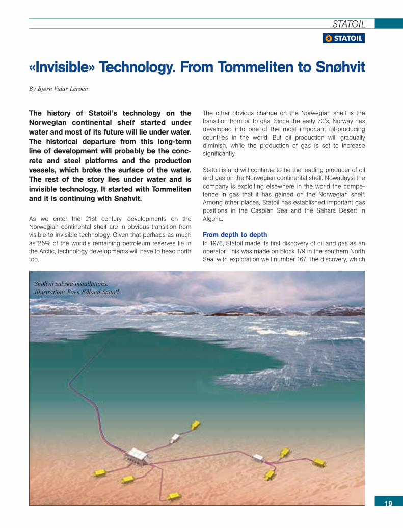
Snøhvit subsea installations.Illustration: Even Edland Statoil
was given the name of Tommeliten, was not large, but itwas important. The company brought its first few litres of oilfrom the successful test well ashore in a couple of jerry-cans. Statoil had become an oil company for real.
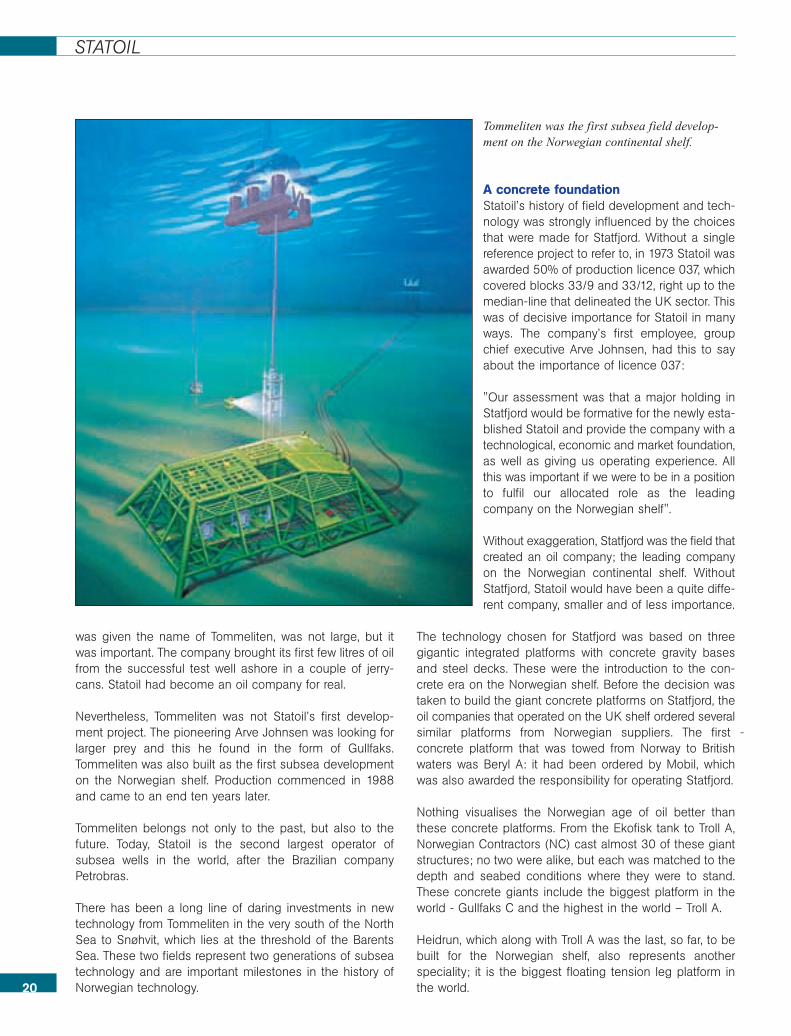
Nevertheless, Tommeliten was not Statoil’s first develop-ment project. The pioneering Arve Johnsen was looking forlarger prey and this he found in the form of Gullfaks.Tommeliten was also built as the first subsea developmenton the Norwegian shelf. Production commenced in 1988and came to an end ten years later.
Tommeliten belongs not only to the past, but also to thefuture. Today, Statoil is the second largest operator ofsubsea wells in the world, after the Brazilian companyPetrobras.
There has been a long line of daring investments in newtechnology from Tommeliten in the very south of the NorthSea to Snøhvit, which lies at the threshold of the BarentsSea. These two fields represent two generations of subseatechnology and are important milestones in the history ofNorwegian technology.
A concrete foundationStatoil’s history of field development and tech-nology was strongly influenced by the choicesthat were made for Statfjord. Without a singlereference project to refer to, in 1973 Statoil wasawarded 50% of production licence 037, whichcovered blocks 33/9 and 33/12, right up to themedian-line that delineated the UK sector. Thiswas of decisive importance for Statoil in manyways. The company’s first employee, groupchief executive Arve Johnsen, had this to sayabout the importance of licence 037:
"Our assessment was that a major holding inStatfjord would be formative for the newly esta-blished Statoil and provide the company with atechnological, economic and market foundation,as well as giving us operating experience. Allthis was important if we were to be in a positionto fulfil our allocated role as the leadingcompany on the Norwegian shelf".
Without exaggeration, Statfjord was the field thatcreated an oil company; the leading companyon the Norwegian continental shelf. WithoutStatfjord, Statoil would have been a quite diffe-rent company, smaller and of less importance.
The technology chosen for Statfjord was based on threegigantic integrated platforms with concrete gravity basesand steel decks. These were the introduction to the con-crete era on the Norwegian shelf. Before the decision wastaken to build the giant concrete platforms on Statfjord, theoil companies that operated on the UK shelf ordered severalsimilar platforms from Norwegian suppliers. The first -concrete platform that was towed from Norway to Britishwaters was Beryl A: it had been ordered by Mobil, whichwas also awarded the responsibility for operating Statfjord.
Nothing visualises the Norwegian age of oil better thanthese concrete platforms. From the Ekofisk tank to Troll A,Norwegian Contractors (NC) cast almost 30 of these giantstructures; no two were alike, but each was matched to thedepth and seabed conditions where they were to stand.These concrete giants include the biggest platform in theworld - Gullfaks C and the highest in the world – Troll A.
Heidrun, which along with Troll A was the last, so far, to bebuilt for the Norwegian shelf, also represents anotherspeciality; it is the biggest floating tension leg platform inthe world.20
STATOIL
Tommeliten was the first subsea field develop-ment on the Norwegian continental shelf.

21
Statoil was a driving force behind such huge concrete tech-nological solutions. After three of them had been orderedfor Statfjord, Statoil’s management felt that copying thethree Statfjord platforms for Gullfaks would offer majorsynergy effects. Statoil also went in for concrete for theSleipner and Troll fields. But that was the end of the concretestory on the Norwegian shelf; at least for the time being.
With the benefit of hindsight it may seem as though usingthree large integrated concrete platforms on Statfjord andGullfaks was a major exaggeration. Not a great deal ofinsight is required to realise that if these two field develop-ments and other similar ones, had taken place today, thingswould have turned out quite differently But that is noreason to conclude that the choice of technology waswrong. The choice must be seen in the light of the techno-logy that was known and available when it was used andthereafter in the light of the results obtained.
November 24, 2004 saw the celebration of 25 years ofproduction on Statfjord. A count would show that the threeplatforms had already delivered oil worth about 170 billiondollars, half of which has been paid in tax. Thorhild Widvey,Minister of Petroleum and Energy, summed up the situationin her own words: "The partners in the Statfjord licencehave paid two million kroner in tax every hour for the past25 years".
Major value from enhanced recoveryOne of the best technology stories from the Norwegian shelfrelates to enhanced oil recovery. When the Stafjord field startedproduction in 1979, the Statfjord group was convinced that thelimit of recovery was 48.4 percent of the rich Jurassic sand-stone reservoir. At that point in time this was a high and ratherdaring estimate, even though only a few years previously, in aWhite Paper on the development of this field, the Ministry ofIndustry had anticipated a recovery rate of 60%. In the White
Gullfaks, one of a total of 30 giant concrete platforms thatwere built in the 80s and 90s for the Norwegian shelf.Photo: Øyvind Hagen, Statoil
STATOIL
Paper, however, the level of ambition was lowered to 50%.After 25 years of production, 63 percent of Statfjord’s reser-ves have been extracted. The story does not stop there. Theaim is now 70% before production is shut in for good . Thetime horizon for late-phase Statfjord is 2020.
Statfjord is a unique field. On January 16, 1987, its best dayever, the three platforms produced 850,204 barrels of oil.
In the course of 25 years, four billion barrels of oil havebeen brought up from Statfjord. There are still interestingamounts of oil left in the field, but the late phase will largelybe a matter of recovering large volumes of gas with the aidof lower pressures. Of the cash flow of 170 billion dollarsbillion, between 30 and 40 billion dollars are the result ofenhanced recovery.
Statfjord lies in the Tampen area together with the Gullfaks,Snorre and Visund fields and a number of satellite fields.On the basis of the current drainage strategy, which willprovide a high recovery rate for all these fields, seven billion
barrels of oil will be left in the ground when production undercurrent conditions ceases. But these are current conditions.Given the rate of technology development that we haveseen on the Norwegian shelf so far, it is unlikely that sucha large amount of oil will simply be abandoned and forgotten.
Floating solutionsIn their different variants, the fixed platforms represent thefirst generation of solutions on the Norwegian shelf. Thesewere followed by the production vessels on Norne andÅsgard, before technology development pointed onceagain to the depths on Snøhvit.
It is not difficult to see that floating production facilities offera much higher degree of flexibility, not least in terms of theirpotential for re-use.
The development of flexible risers from the fixed installationsand to the production vessels and floating production plat-forms was a quite decisive factor in our ability to go in forfloating installations.22
STATOIL
Hammerfest, with the Snøhvit terminal on Melkøya in the backgroundPhoto: Svein-Arne Rollstad

World champion in pipelines and multiphase flowAs far back as the early 1980s, Statoil believed that multip-hase technology would come to be of decisive importancefor future field developments on the Norwegian continentalshelf. Yet again, a picture of daring: Arve Johnsen wasready and willing to put almost 100 million dollars into thedevelopment of a technology whose outcome no-onecould predict.
Multiphase technology made a dramatic breakthrough inthe development of the Troll gas field. The original plans forthe development of this field were based on the concept ofan integrated platform for drilling, production, processsystems and living quarters. The planning process revealedthat such a platform would simply be too heavy and wouldhave too great a draught, which would make it impossibleto tow from the shipyard in Norway out to the field.
Statoil challenged Shell, the development operator, with aproposal to move the platform’s process plant ashore. Theresult was the gas treatment terminal at Kollsnes inØygarden. However, this required the multiphase technology
involved to be documented so well that it could be trans-ferred from the drawing board and test loops to industrialuse in the North Sea.
The successful introduction of multiphase technology onTroll was of decisive importance for the development ofSnøhvit. While the multiphase pipeline from Troll to Kollsnesis 63 kilometres long, the next step was 143.3 kilometres,which is the distance from the subsea installations onSnøhvit to the LNG terminal at Melkøya outside Hammer-fest, the northernmost city in the world.
No other company has laid as many kilometres of subseapipelines as Statoil. When Langeled, the pipeline connectionbetween the Ormen Lange field in the Norwegian Sea andEasington in the UK is ready, Statoil will have laid more than7,000 kilometres of subsea pipelines from the Norwegianshelf.
When Arve Johnsen was asked what had been Statoil’smost important achievement during its fifteen years underhis leadership, he replied that it was Statpipe.
23
Åsgard A. Production vessels replaced concrete platforms,but the future is down in the depths again, on Snøhvit.Photo: Øyvind Hagen, Statoil
STATOIL
Statpipe was a breakthrough in both technological and marketterms, which formed the basis of the Norwegian gas machine.
Technological daring"Statoil will be an early and daring user of technology", saidHelge Lund as he took over as the fourth chief executive ofthe Statoil Group in August 2004. Two of his predecessorshad been forced to resign following cost overruns in majorprojects; Mongstad and Åsgard.
Major deviations from cost estimates – and it is important toremember that these can go in either direction – are difficultto defend in isolation. However, they can be explained interms of the fact that the development and utilisation ofnew technology often take place at high cost and with highpotential gains.
Statoil’s investments in technology, which have taken placein close collaboration with the Norwegian and internationalsupply industry, have been based on the idea that it isimportant to be in command of the whole value chain: fromsource to consumer. In the areas of exploration and pro-duction on the Norwegian shelf, this involves an ambition tobe the leading operating company from the explorationphase and field development and throughout the wholeoperating phase to tail-end production.
24
STATOIL
The Statfjord field has produced oil worth well over 170 billiondollars, half of which it has given to the Norwegian state inthe form of tax and duty. Photo: Øyvind Hagen, Statoil
Arve Johnsen, the first head of Statoil, was willing to putalmost 100 million dollars into the development of multiphasetechnology, which got its breakthrough on the Troll field andwas of decisive importance for the development of Snøhvit.Photo: Dag Magne Søyland
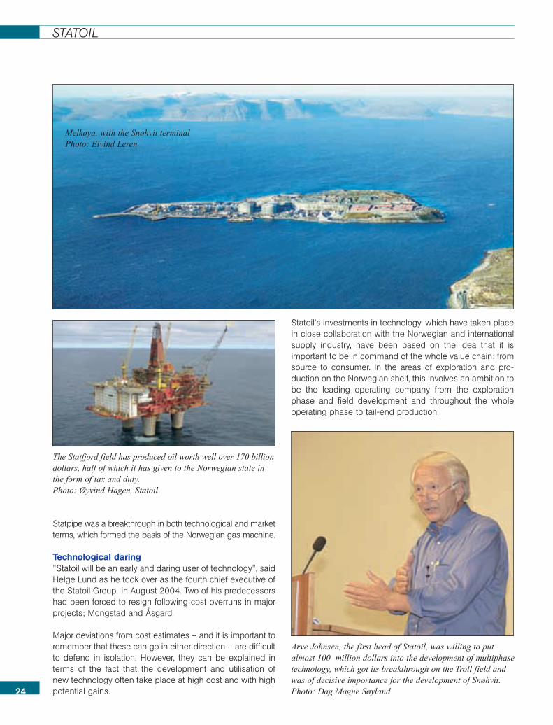
Melkøya, with the Snøhvit terminalPhoto: Eivind Leren
25
Hydro
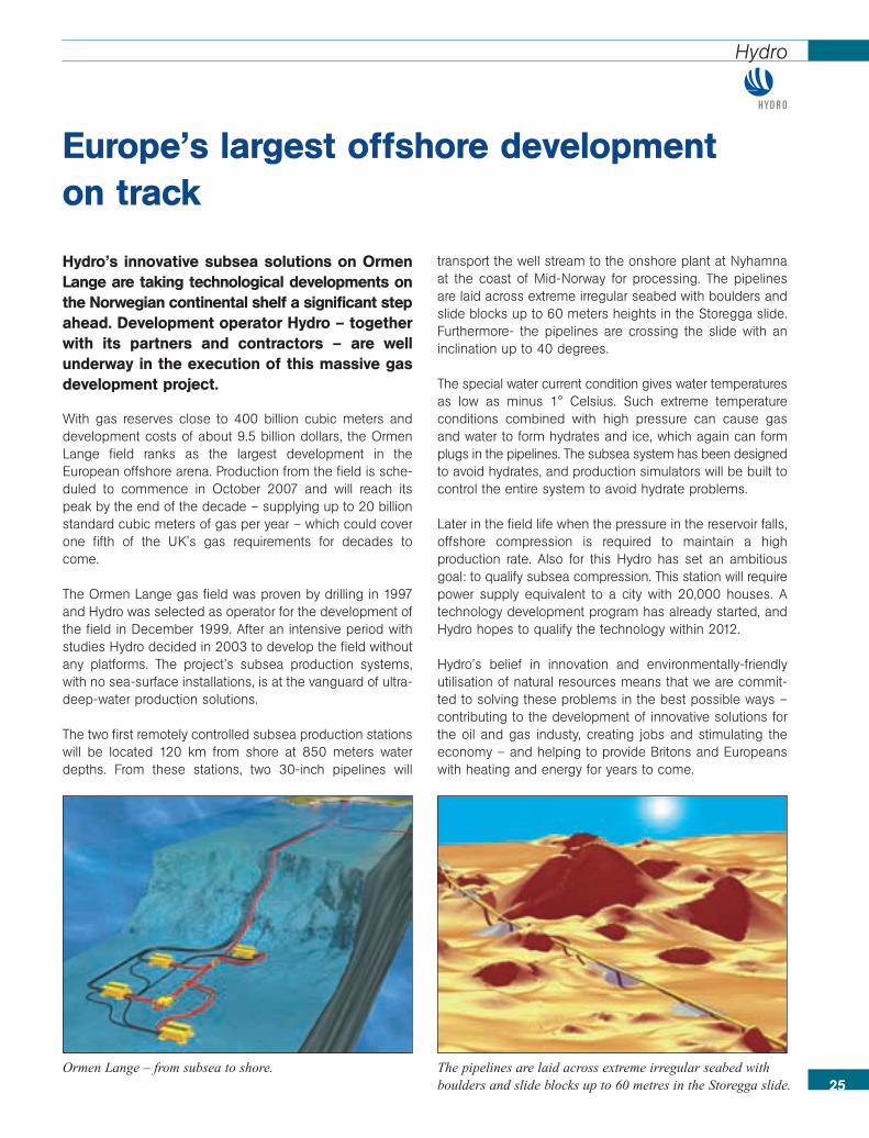
Hydro’s innovative subsea solutions on OrmenLange are taking technological developments onthe Norwegian continental shelf a significant stepahead. Development operator Hydro – togetherwith its partners and contractors – are wellunderway in the execution of this massive gasdevelopment project.
With gas reserves close to 400 billion cubic meters anddevelopment costs of about 9.5 billion dollars, the OrmenLange field ranks as the largest development in theEuropean offshore arena. Production from the field is sche-duled to commence in October 2007 and will reach itspeak by the end of the decade – supplying up to 20 billionstandard cubic meters of gas per year – which could coverone fifth of the UK's gas requirements for decades tocome.
The Ormen Lange gas field was proven by drilling in 1997and Hydro was selected as operator for the development ofthe field in December 1999. After an intensive period withstudies Hydro decided in 2003 to develop the field withoutany platforms. The project’s subsea production systems,with no sea-surface installations, is at the vanguard of ultra-deep-water production solutions.
The two first remotely controlled subsea production stationswill be located 120 km from shore at 850 meters waterdepths. From these stations, two 30-inch pipelines will
transport the well stream to the onshore plant at Nyhamnaat the coast of Mid-Norway for processing. The pipelinesare laid across extreme irregular seabed with boulders andslide blocks up to 60 meters heights in the Storegga slide.Furthermore- the pipelines are crossing the slide with aninclination up to 40 degrees.
The special water current condition gives water temperaturesas low as minus 1° Celsius. Such extreme temperatureconditions combined with high pressure can cause gasand water to form hydrates and ice, which again can formplugs in the pipelines. The subsea system has been designedto avoid hydrates, and production simulators will be built tocontrol the entire system to avoid hydrate problems.
Later in the field life when the pressure in the reservoir falls,offshore compression is required to maintain a highproduction rate. Also for this Hydro has set an ambitiousgoal: to qualify subsea compression. This station will requirepower supply equivalent to a city with 20,000 houses. Atechnology development program has already started, andHydro hopes to qualify the technology within 2012.
Hydro’s belief in innovation and environmentally-friendlyutilisation of natural resources means that we are commit-ted to solving these problems in the best possible ways –contributing to the development of innovative solutions forthe oil and gas industy, creating jobs and stimulating theeconomy – and helping to provide Britons and Europeanswith heating and energy for years to come.
Europe’s largest offshore development on track
Ormen Lange – from subsea to shore. The pipelines are laid across extreme irregular seabed withboulders and slide blocks up to 60 metres in the Storegga slide.
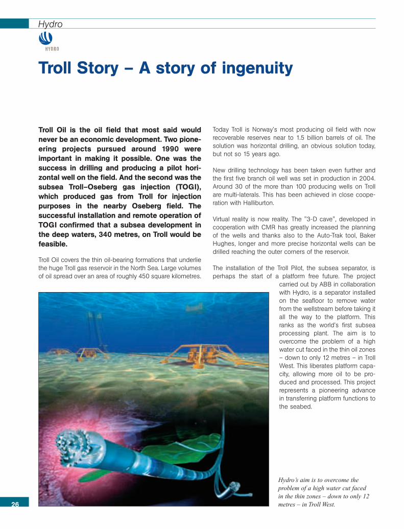
Troll Oil is the oil field that most said wouldnever be an economic development. Two pione-ering projects pursued around 1990 wereimportant in making it possible. One was thesuccess in drilling and producing a pilot hori-zontal well on the field. And the second was thesubsea Troll–Oseberg gas injection (TOGI),which produced gas from Troll for injectionpurposes in the nearby Oseberg field. Thesuccessful installation and remote operation ofTOGI confirmed that a subsea development inthe deep waters, 340 metres, on Troll would befeasible.
Troll Oil covers the thin oil-bearing formations that underliethe huge Troll gas reservoir in the North Sea. Large volumesof oil spread over an area of roughly 450 square kilometres.
Today Troll is Norway’s most producing oil field with nowrecoverable reserves near to 1.5 billion barrels of oil. Thesolution was horizontal drilling, an obvious solution today,but not so 15 years ago.
New drilling technology has been taken even further andthe first five branch oil well was set in production in 2004.Around 30 of the more than 100 producing wells on Trollare multi-laterals. This has been achieved in close coope-ration with Halliburton.
Virtual reality is now reality. The "3-D cave", developed incooperation with CMR has greatly increased the planningof the wells and thanks also to the Auto-Trak tool, BakerHughes, longer and more precise horizontal wells can bedrilled reaching the outer corners of the reservoir.
The installation of the Troll Pilot, the subsea separator, isperhaps the start of a platform free future. The project
carried out by ABB in collaborationwith Hydro, is a separator installedon the seafloor to remove waterfrom the wellstream before taking itall the way to the platform. Thisranks as the world’s first subseaprocessing plant. The aim is toovercome the problem of a highwater cut faced in the thin oil zones– down to only 12 metres – in TrollWest. This liberates platform capa-city, allowing more oil to be pro-duced and processed. This projectrepresents a pioneering advancein transferring platform functions tothe seabed.
Troll Story – A story of ingenuity
26
Hydro
Hydro’s aim is to overcome theproblem of a high water cut faced in the thin zones – down to only 12metres – in Troll West.

The Continental Shelf Institute (IKU), whichlater merged with SINTEF, played an importantrole in the studies that led Norway into the ageof oil. The Institute was set up by the Ministryof Industry in 1969 under the name of NTNF-K,in order to perform studies of the Norwegiancontinental shelf and gather data which theauthorities would use when they were selectingblocks for licensing rounds. This knowledge hasbeen invaluable for Norway’s management ofits petroleum resources.
The reasons given by the authorities for setting up IKU were"to obtain the information and expertise that will enable theauthorities to dispose of the resources of the shelf in thebest interests of the country". NTNF-K was made respon-sible for four functions: petroleum investigations north of62° N, long-term scientific investigations, the developmentof technology and the development of professional exper-tise. The Institute has changed its name a number of times,and is now known as SINTEF Petroleum Research.
Mapping the upper layers of the seabed During its first years of existence, one of IKU’s main areasof activity was mapping the uppermost strata of the seabedby means of shallow seismics techniques. Extensivecollections were also made of material from the seabed,forming the basis of maps of the condition of the seabed.
The material was studied with the aim of determining theusual range of geotechnical characteristics, sediment type,mineralogy, organic geochemistry (characterizing types ofsource rock and possible hydrocarbon leaks) and dating.Maps of types of seabed were made for large parts of theNorwegian shelf. These were of great value for both thepetroleum sector and the fishing industry.
Special studies worth mentioning include the Storegga-raset landslide, which is 800 km long, and is one of thelargest submarine slides ever surveyed on the Earth.
Projects in collaboration with industryData from Norwegian Arctic regions were important for ourunderstanding of the subsea regions of the Barents Sea,even before exploration drilling for hydrocarbons beganthere in the early 80s. Svalbard and Bjørnøya is an upliftregion of the Barents shelf itself, which means that they areof great value for understanding the whole region.
For this reason, IKU carried out active field work andsampling on Svalbard, often in collaboration with universitiesand oil companies. These projects fell into several cate-gories: sedimentology studies focused on developinggeological models that could also be used in the BarentsSea. Palaeontological studies made it possible to performgood dating and correlations in the new exploration wells inthe Barents Sea. Organic geochemical studies were carriedout with the aim of mapping and characterising source rockthat might be expected to be of importance in the BarentsSea. Integrated studies put all of these studies into a unifiedcontext and helped us to produce comprehensive synt-heses of the whole northern region.
From the mid-80s onwards, the studies were extended toinclude Russian, Danish and Canadian colleagues. A greatdeal of Russian material came to the notice of Western oilcompanies for the first time as a result of these projects. All inall, more than 100 reports were generated by these projects.
Shallow stratigraphic drillingBetween 1982 and 1994, IKU mapped parts of theNorwegian continental shelf with the aid of shallow, high-resolution seismics, combined with shallow stratigraphicdrilling.
This industry-financed work resulted in about 6,600 m ofhigh-quality cores of sedimentary rocks.
The material produced by this drilling programme is stillbeing actively used by the industry. The last drilling campaignfor the Norwegian Petroleum Directorate took place in 1998.
Research enters the age of oil
28
SINTEF – The Continental Shelf Institute
Remotely controlled mini-drilling rig used in the 1980ies.
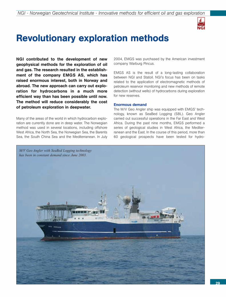
NGI contributed to the development of newgeophysical methods for the exploration of oiland gas. The research resulted in the establish-ment of the company EMGS AS, which hasraised enormous interest, both in Norway andabroad. The new approach can carry out explo-ration for hydrocarbons in a much moreefficient way than has been possible until now.The method will reduce considerably the costof petroleum exploration in deepwater.
Many of the areas of the world in which hydrocarbon explo-ration are currently done are in deep water. The Norwegianmethod was used in several locations, including offshoreWest Africa, the North Sea, the Norwegian Sea, the BarentsSea, the South China Sea and the Mediterranean. In July
2004, EMGS was purchased by the American investmentcompany Warburg Pincus.
EMGS AS is the result of a long-lasting collaborationbetween NGI and Statoil. NGI’s focus has been on tasksrelated to the application of electromagnetic methods ofpetroleum reservoir monitoring and new methods of remotedetection (without wells) of hydrocarbons during explorationfor new reserves.
Enormous demandThe M/V Geo Angler ship was equipped with EMGS’ tech-nology, known as SeaBed Logging (SBL). Geo Anglercarried out successful operations in the Far East and WestAfrica. During the past nine months, EMGS performed aseries of geological studies in West Africa, the Mediter-ranean and the East. In the course of this period, more than60 geological prospects have been tested for hydro-
Revolutionary exploration methods
29
NGI - Norwegian Geotechnical Institute - Innovative methods for efficient oil and gas exploration
M/V Geo Angler with SeaBed Logging technologyhas been in constant demand since June 2003.

30
NGI – Norwegian Geotechnical Institute – Innovative methods for efficient oil and gas exploration
carbons. The vessel recently returned to European watersto carry out more studies.
The enormous demand for the new technology demonstratesthe importance and relevance of the research. The custo-mers asking for more surveys use the results for bothexploration and for delineating the fields.
Can be used in all watersSBL surveys can be carried out in all sorts of weather andat depths ranging from 200 m to 3000 m, which meansthat the method can be used for virtually all petroleumsurveys offshore.
The large number of tests that have already been carriedout show that the EMGS technology patented can be utili-sed in most types of sedimentary basins and under a widerange of geological conditions. The convincing resultsobtained so far have led to a growing interest in both thecompany and its technology, especially abroad.
Petroleum geomechanicsThe research that led to the establishment of EMGS is onlyone of several areas in which NGI actively contributed toinnovation bringing new patents and a competitive advan-tage to the research sponsors, and to the improvement ofexploitation of resources on the Norwegian shelf.
The development of methods for evaluating and explainingthe subsidence of the Ekofisk field was the start of petro-leum geomechanics as a research field at NGI. Expertise atNGI on the mechanical behaviour of the clay shale sedi-ment and reservoir chalk rock helped lower drilling and wellcosts.
NGI contributes to enhanced recovery through numericalanalyses of mechanical behaviour in and above the reser-voir. Included here are flow in fractured formations, labora-tory studies, numerical modelling of multiphase flow andevaluation of wellbore stability.
NGI developed a new method of modelling geomechanicalproblems associated with production from oil and gasreservoirs. The method is based on the development ofnew modules in commercially available geological model-ling software to, for example, analyse reservoir compression,seabed settlement, sand production and wellbore stability.
Water injection reduces the reservoir material strength andstiffness. NGI developed laboratory methods for registeringthe distribution of fluid and to measure acoustic wavevelocity while a sample is being filled with water. The tech-niques make use of computerised tomography (CT) andacoustic methods.
NGI tested the method for BP on the Valhall field, to docu-ment the effects of water injection in oil-saturated chalk.The idea is to enable the creation of a picture of the flowpattern of flow in the chalk material.
The SBL receiver deployed on the seabed to register low-fre-quency electromagnetic signals.
CT image of water injection in petroleum reservoirs
31
Kongsberg Maritime – HUGIN
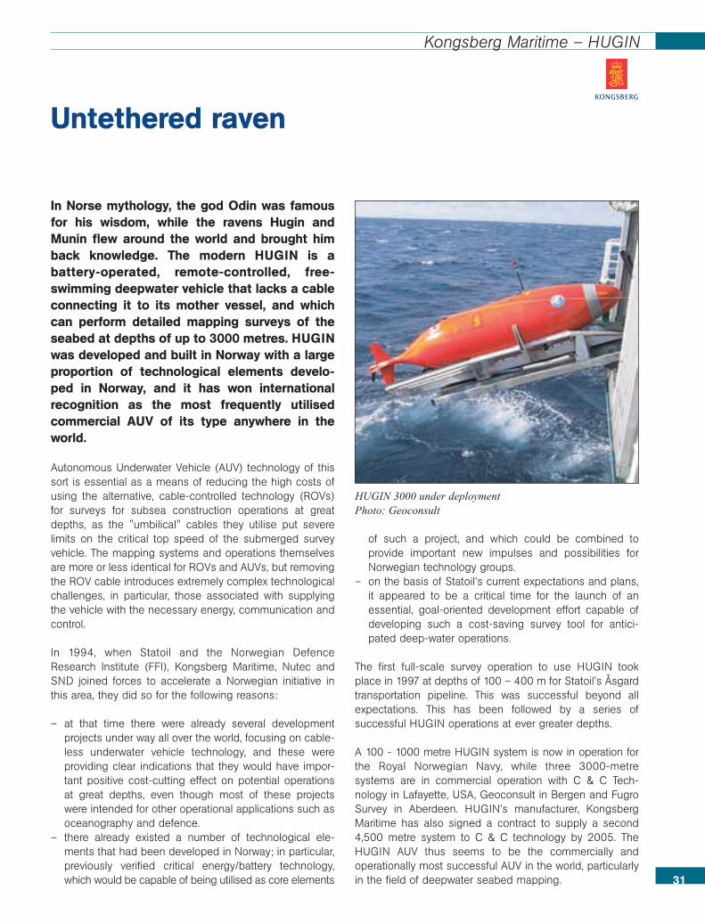
In Norse mythology, the god Odin was famousfor his wisdom, while the ravens Hugin andMunin flew around the world and brought himback knowledge. The modern HUGIN is abattery-operated, remote-controlled, free-swimming deepwater vehicle that lacks a cableconnecting it to its mother vessel, and whichcan perform detailed mapping surveys of theseabed at depths of up to 3000 metres. HUGINwas developed and built in Norway with a largeproportion of technological elements develo-ped in Norway, and it has won internationalrecognition as the most frequently utilisedcommercial AUV of its type anywhere in theworld.
Autonomous Underwater Vehicle (AUV) technology of thissort is essential as a means of reducing the high costs ofusing the alternative, cable-controlled technology (ROVs)for surveys for subsea construction operations at greatdepths, as the "umbilical" cables they utilise put severelimits on the critical top speed of the submerged surveyvehicle. The mapping systems and operations themselvesare more or less identical for ROVs and AUVs, but removingthe ROV cable introduces extremely complex technologicalchallenges, in particular, those associated with supplyingthe vehicle with the necessary energy, communication andcontrol.
In 1994, when Statoil and the Norwegian DefenceResearch Institute (FFI), Kongsberg Maritime, Nutec andSND joined forces to accelerate a Norwegian initiative inthis area, they did so for the following reasons:
– at that time there were already several developmentprojects under way all over the world, focusing on cable-less underwater vehicle technology, and these wereproviding clear indications that they would have impor-tant positive cost-cutting effect on potential operationsat great depths, even though most of these projectswere intended for other operational applications such asoceanography and defence.
– there already existed a number of technological ele-ments that had been developed in Norway; in particular,previously verified critical energy/battery technology,which would be capable of being utilised as core elements
of such a project, and which could be combined toprovide important new impulses and possibilities forNorwegian technology groups.
– on the basis of Statoil’s current expectations and plans,it appeared to be a critical time for the launch of anessential, goal-oriented development effort capable ofdeveloping such a cost-saving survey tool for antici-pated deep-water operations.
The first full-scale survey operation to use HUGIN tookplace in 1997 at depths of 100 – 400 m for Statoil’s Åsgardtransportation pipeline. This was successful beyond allexpectations. This has been followed by a series ofsuccessful HUGIN operations at ever greater depths.
A 100 - 1000 metre HUGIN system is now in operation forthe Royal Norwegian Navy, while three 3000-metresystems are in commercial operation with C & C Tech-nology in Lafayette, USA, Geoconsult in Bergen and FugroSurvey in Aberdeen. HUGIN’s manufacturer, KongsbergMaritime has also signed a contract to supply a second4,500 metre system to C & C technology by 2005. TheHUGIN AUV thus seems to be the commercially andoperationally most successful AUV in the world, particularlyin the field of deepwater seabed mapping.
Untethered raven
HUGIN 3000 under deploymentPhoto: Geoconsult
An exploration well typically costs 15 - 25 milliondollars. The SEMI basin simulator has reducedthe number of dry wells and made significantsavings for the oil companies in the course ofthe past ten years. The improved discovery ratehas created huge value for the oil companiesand the Norwegian state.
An understanding of the basin and its petroleum system isimportant for our efforts to find oil and gas. This is whySINTEF has been working on the development of basinmodelling software since 1986, and has developed SEMI3D, which is one of the most advanced basin simulators inthe world. A large number of oil companies are usingSINTEF’s basin simulation software in their everyday explo-ration activities, and several have improved the successrates of their exploration wells with the aid of these tools.The aim of the project has been to supply the oil companies’
exploration divisions with quantitative estimates of oil andgas volumes in undrilled prospects and to predict the mostlikely hydrocarbon phases and compositions to be expected.
A thorough understanding of the geological development ofa basin is essential in order to carry out a rational processof exploration with the lowest possible risk of making poordecisions. This produces a huge number of challenges forthe oil companies’ exploration departments.
Basin modelling, which aims to understand and quantifygeological processes, is a research field in rapid develop-ment.
The first version of the SEMI basin modelling softwarepackage was developed by SINTEF Petroleum Research in1986. SEMI employs a raytracing methodology to modelthe movement of oil and gas in three dimensions alongpermeable layers. One of the challenges lies in followingthe hydrocarbons from their source past faults and otherbarriers until they are caught in a trap, or leak verticallyupwards to the next porous layer or all the way to thesurface. The results are calibrated against existing fieldsand dry wells by systematically varying individual para-meters and assumptions of the model. This is done to testthe sensitivity of the modelled processes to uncertainties in
the geological model and thus improve the pre-dictability of finding oil and gas. This has
now become a recognised methodwhich is used by the petroleum indus-try to assist it in quantifying the likeli-hood of making discoveries in undrilledexploration targets.
This software deals with extremelylarge geological models of high com-plexity, and its simulation times are veryshort in comparison with other 3Dbasin modelling simulators. Thismeans that it is also possible to per-
form stochastic simulations in order toreduce the uncertainty of exploration drilling
even further. SEMI 3D now forms part of SINTEF’s compre-hensive software suite, which includes a number of 3Dsimulators for basin studies. Several of these new toolshave been financed by the Research Council of Norway.With these advanced software tools, SINTEF is a participantin every new licensing round on the Norwegian shelf,helping the oil companies to evaluate the blocks that havebeen advertised for licensing.
SEMI 3D improves discovery rates
32
SINTEF – Semi 3D Basin simulator
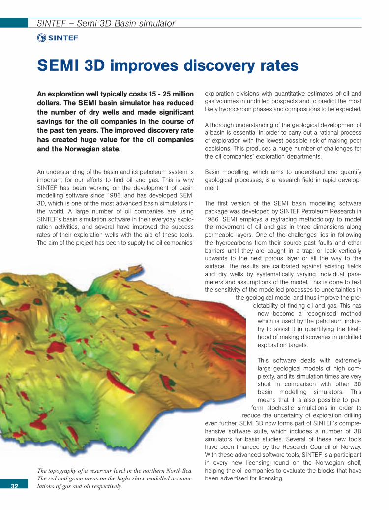
The topography of a reservoir level in the northern North Sea.The red and green areas on the highs show modelled accumu-lations of gas and oil respectively.
Petroleum exploration is characterised by highmargins of uncertainty in discovery rates andexpected volumes of hydrocarbons. The mostimportant factors influencing the formation ofpetroleum are temperature and time. The tem-perature history of a basin is controlled by anumber of geological processes that havetaken place in the course of the history of thebasin.
It has been demonstrated that, to make a realisticconstruction of the temperature history of a basin, it isextremely important to be able to develop an adequaterepresentation of the geometry of the basin and reconstructits development in a realistic way. If there are serious errorsin the geometry of the present or the past, predictions ofthe temperature history of the basin will be wrong. It is alsoimportant to be able to model other tectonic processessuch as salt movements and volcanic activity, as well asother important processes that influence heat flow from thecentre of the Earth.
BMT™ is a powerful system for the analysis of interactionsbetween tectonic processes, heat flow, and time offormation of hydrocarbons. The system reconstructs thegeometric development of the basin, with modelling offaults, including both normal and reverse faults.
BMT™ is used to simulate the geological processes thatinfluence the temperature history and formation of hydro-carbons throughout the history of a basin, including thefollowing processes:
• Sediment deposits - erosion and compaction• Reconstruction of normal or reverse faults• Used-guided modelling of salt geometries• Isostatic response to deposits, erosion and fault activity• Tectonic response to crust thinning• Heat flow into the basin as a result of lithosphere thinning• Hydrocarbon maturation
The combination of tectonic modelling and temperaturemodelling makes BMT™ a unique tool of its type. It wasdeveloped by RF-Rogaland Research by a team of geosci-entists, mathematicians and software engineers. Thesystem has been under continuous development since
1987, with the support of the Research Council of Norway,among other sources of finance.
BMT™ has been used by several companies for explorationstudies and in research on the Norwegian continental shelf,the Barents Sea, the North Sea and the Norwegian Sea.Several of these studies have been published in inter-national journals. The estimates of temperature historymatch observed data well. The software has also beenused in international studies for example on the UK shelfand in Turkey, Africa, Asia and South America. BMT™ isbeing used for teaching and research purposes by theUniversities of Oslo, Bergen, Tromsø and in Stavanger.
33
RF – Rogaland Research – Basin models
Temperature – the most importantunknown factor in exploration
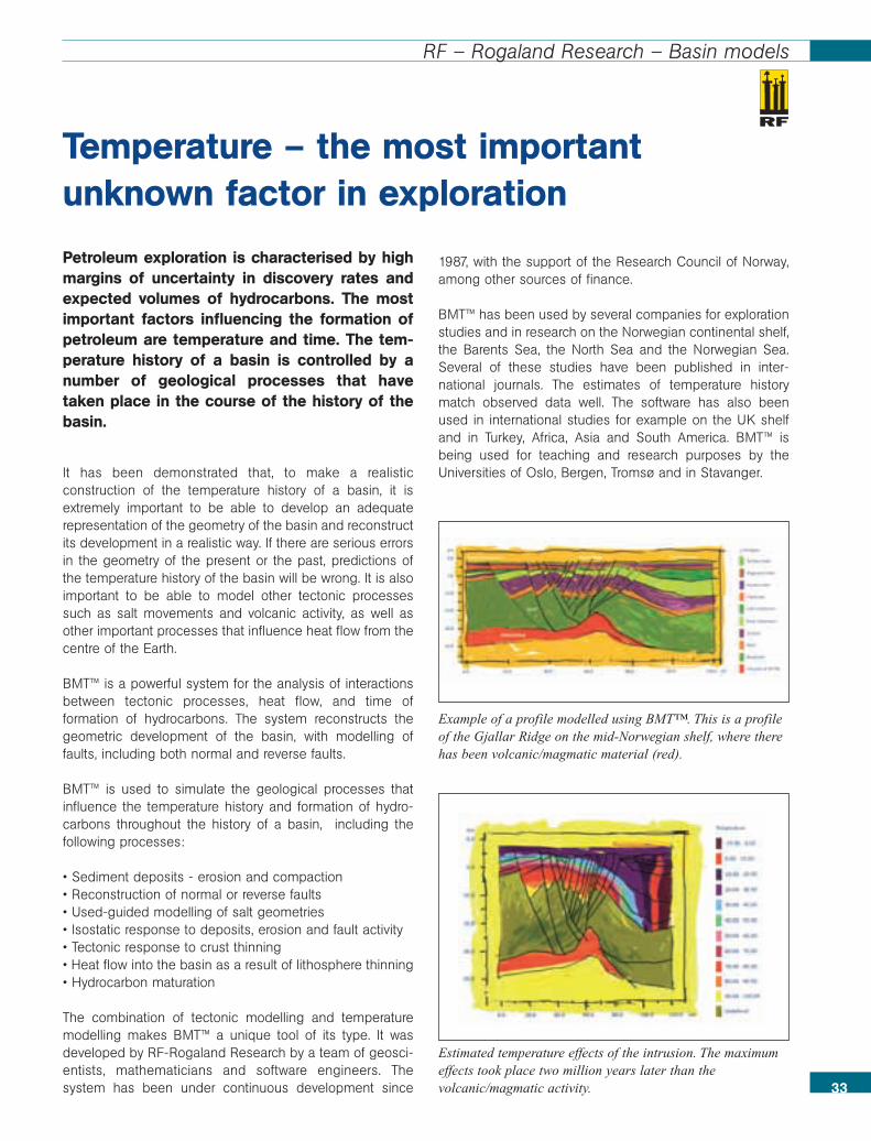
Example of a profile modelled using BMT™. This is a profileof the Gjallar Ridge on the mid-Norwegian shelf, where therehas been volcanic/magmatic material (red).
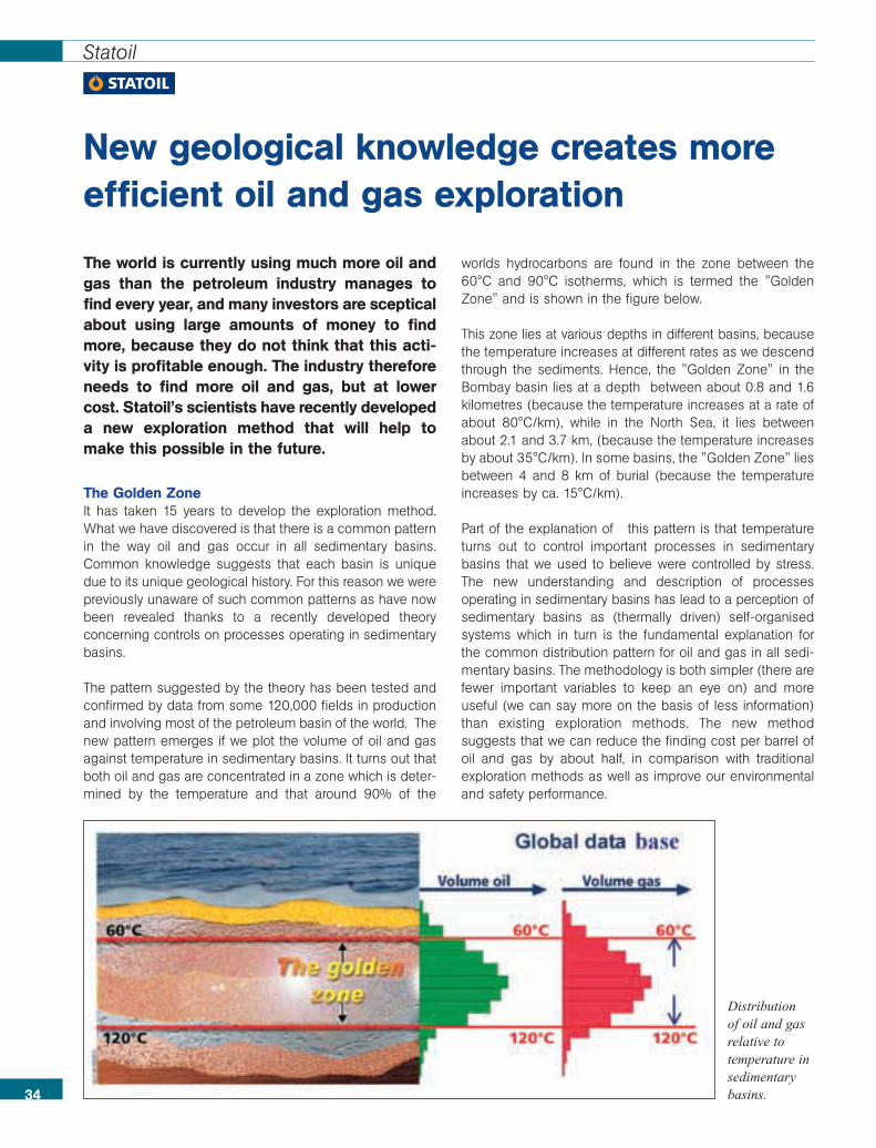
Estimated temperature effects of the intrusion. The maximumeffects took place two million years later than thevolcanic/magmatic activity.
The world is currently using much more oil andgas than the petroleum industry manages tofind every year, and many investors are scepticalabout using large amounts of money to findmore, because they do not think that this acti-vity is profitable enough. The industry thereforeneeds to find more oil and gas, but at lowercost. Statoil’s scientists have recently developeda new exploration method that will help tomake this possible in the future.
The Golden ZoneIt has taken 15 years to develop the exploration method.What we have discovered is that there is a common patternin the way oil and gas occur in all sedimentary basins.Common knowledge suggests that each basin is uniquedue to its unique geological history. For this reason we werepreviously unaware of such common patterns as have nowbeen revealed thanks to a recently developed theoryconcerning controls on processes operating in sedimentarybasins.
The pattern suggested by the theory has been tested andconfirmed by data from some 120,000 fields in productionand involving most of the petroleum basin of the world. Thenew pattern emerges if we plot the volume of oil and gasagainst temperature in sedimentary basins. It turns out thatboth oil and gas are concentrated in a zone which is deter-mined by the temperature and that around 90% of the
worlds hydrocarbons are found in the zone between the60°C and 90°C isotherms, which is termed the "GoldenZone" and is shown in the figure below.
This zone lies at various depths in different basins, becausethe temperature increases at different rates as we descendthrough the sediments. Hence, the "Golden Zone" in theBombay basin lies at a depth between about 0.8 and 1.6kilometres (because the temperature increases at a rate ofabout 80°C/km), while in the North Sea, it lies betweenabout 2.1 and 3.7 km, (because the temperature increasesby about 35°C/km). In some basins, the "Golden Zone" liesbetween 4 and 8 km of burial (because the temperatureincreases by ca. 15°C/km).
Part of the explanation of this pattern is that temperatureturns out to control important processes in sedimentarybasins that we used to believe were controlled by stress.The new understanding and description of processesoperating in sedimentary basins has lead to a perception ofsedimentary basins as (thermally driven) self-organisedsystems which in turn is the fundamental explanation forthe common distribution pattern for oil and gas in all sedi-mentary basins. The methodology is both simpler (there arefewer important variables to keep an eye on) and moreuseful (we can say more on the basis of less information)than existing exploration methods. The new methodsuggests that we can reduce the finding cost per barrel ofoil and gas by about half, in comparison with traditionalexploration methods as well as improve our environmentaland safety performance.
New geological knowledge creates moreefficient oil and gas exploration
34
Statoil
Distributionof oil and gasrelative totemperature insedimentarybasins.
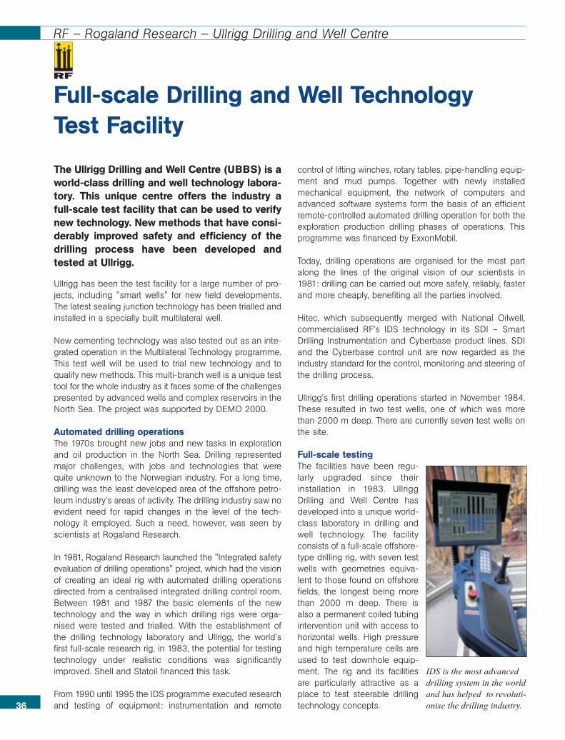
The Ullrigg Drilling and Well Centre (UBBS) is aworld-class drilling and well technology labora-tory. This unique centre offers the industry afull-scale test facility that can be used to verifynew technology. New methods that have consi-derably improved safety and efficiency of thedrilling process have been developed andtested at Ullrigg.
Ullrigg has been the test facility for a large number of pro-jects, including "smart wells" for new field developments.The latest sealing junction technology has been trialled andinstalled in a specially built multilateral well.
New cementing technology was also tested out as an inte-grated operation in the Multilateral Technology programme.This test well will be used to trial new technology and toqualify new methods. This multi-branch well is a unique testtool for the whole industry as it faces some of the challengespresented by advanced wells and complex reservoirs in theNorth Sea. The project was supported by DEMO 2000.
Automated drilling operationsThe 1970s brought new jobs and new tasks in explorationand oil production in the North Sea. Drilling representedmajor challenges, with jobs and technologies that werequite unknown to the Norwegian industry. For a long time,drilling was the least developed area of the offshore petro-leum industry’s areas of activity. The drilling industry saw noevident need for rapid changes in the level of the tech-nology it employed. Such a need, however, was seen byscientists at Rogaland Research.
In 1981, Rogaland Research launched the "Integrated safetyevaluation of drilling operations" project, which had the visionof creating an ideal rig with automated drilling operationsdirected from a centralised integrated drilling control room.Between 1981 and 1987 the basic elements of the newtechnology and the way in which drilling rigs were orga-nised were tested and trialled. With the establishment ofthe drilling technology laboratory and Ullrigg, the world’sfirst full-scale research rig, in 1983, the potential for testingtechnology under realistic conditions was significantlyimproved. Shell and Statoil financed this task.
From 1990 until 1995 the IDS programme executed researchand testing of equipment: instrumentation and remote
control of lifting winches, rotary tables, pipe-handling equip-ment and mud pumps. Together with newly installedmechanical equipment, the network of computers andadvanced software systems form the basis of an efficientremote-controlled automated drilling operation for both theexploration production drilling phases of operations. Thisprogramme was financed by ExxonMobil.
Today, drilling operations are organised for the most partalong the lines of the original vision of our scientists in1981: drilling can be carried out more safely, reliably, fasterand more cheaply, benefiting all the parties involved.
Hitec, which subsequently merged with National Oilwell,commercialised RF’s IDS technology in its SDI – SmartDrilling Instrumentation and Cyberbase product lines. SDIand the Cyberbase control unit are now regarded as theindustry standard for the control, monitoring and steering ofthe drilling process.
Ullrigg’s first drilling operations started in November 1984.These resulted in two test wells, one of which was morethan 2000 m deep. There are currently seven test wells onthe site.
Full-scale testingThe facilities have been regu-larly upgraded since theirinstallation in 1983. UllriggDrilling and Well Centre hasdeveloped into a unique world-class laboratory in drilling andwell technology. The facilityconsists of a full-scale offshore-type drilling rig, with seven testwells with geometries equiva-lent to those found on offshorefields, the longest being morethan 2000 m deep. There isalso a permanent coiled tubingintervention unit with access tohorizontal wells. High pressureand high temperature cells areused to test downhole equip-ment. The rig and its facilitiesare particularly attractive as aplace to test steerable drillingtechnology concepts.
Full-scale Drilling and Well TechnologyTest Facility
36
RF – Rogaland Research – Ullrigg Drilling and Well Centre
IDS is the most advanceddrilling system in the worldand has helped to revoluti-onise the drilling industry.
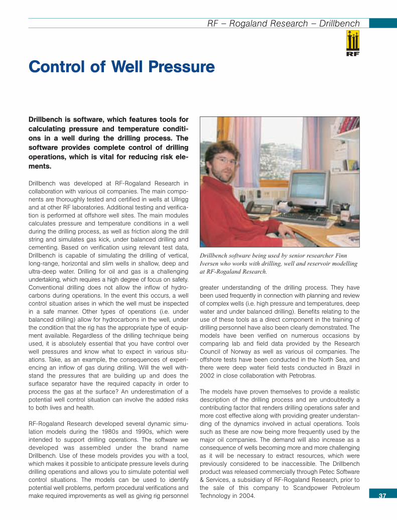
Drillbench is software, which features tools forcalculating pressure and temperature conditi-ons in a well during the drilling process. Thesoftware provides complete control of drillingoperations, which is vital for reducing risk ele-ments.
Drillbench was developed at RF-Rogaland Research incollaboration with various oil companies. The main compo-nents are thoroughly tested and certified in wells at Ullriggand at other RF laboratories. Additional testing and verifica-tion is performed at offshore well sites. The main modulescalculates pressure and temperature conditions in a wellduring the drilling process, as well as friction along the drillstring and simulates gas kick, under balanced drilling andcementing. Based on verification using relevant test data,Drillbench is capable of simulating the drilling of vertical,long-range, horizontal and slim wells in shallow, deep andultra-deep water. Drilling for oil and gas is a challengingundertaking, which requires a high degree of focus on safety.Conventional drilling does not allow the inflow of hydro-carbons during operations. In the event this occurs, a wellcontrol situation arises in which the well must be inspectedin a safe manner. Other types of operations (i.e. underbalanced drilling) allow for hydrocarbons in the well, underthe condition that the rig has the appropriate type of equip-ment available. Regardless of the drilling technique beingused, it is absolutely essential that you have control overwell pressures and know what to expect in various situ-ations. Take, as an example, the consequences of experi-encing an inflow of gas during drilling. Will the well with-stand the pressures that are building up and does thesurface separator have the required capacity in order toprocess the gas at the surface? An underestimation of apotential well control situation can involve the added risksto both lives and health.
RF-Rogaland Research developed several dynamic simu-lation models during the 1980s and 1990s, which wereintended to support drilling operations. The software wedeveloped was assembled under the brand nameDrillbench. Use of these models provides you with a tool,which makes it possible to anticipate pressure levels duringdrilling operations and allows you to simulate potential wellcontrol situations. The models can be used to identifypotential well problems, perform procedural verifications andmake required improvements as well as giving rig personnel
greater understanding of the drilling process. They havebeen used frequently in connection with planning and reviewof complex wells (i.e. high pressure and temperatures, deepwater and under balanced drilling). Benefits relating to theuse of these tools as a direct component in the training ofdrilling personnel have also been clearly demonstrated. Themodels have been verified on numerous occasions bycomparing lab and field data provided by the ResearchCouncil of Norway as well as various oil companies. Theoffshore tests have been conducted in the North Sea, andthere were deep water field tests conducted in Brazil in2002 in close collaboration with Petrobras.
The models have proven themselves to provide a realisticdescription of the drilling process and are undoubtedly acontributing factor that renders drilling operations safer andmore cost effective along with providing greater understan-ding of the dynamics involved in actual operations. Toolssuch as these are now being more frequently used by themajor oil companies. The demand will also increase as aconsequence of wells becoming more and more challengingas it will be necessary to extract resources, which werepreviously considered to be inaccessible. The Drillbenchproduct was released commercially through Petec Software& Services, a subsidiary of RF-Rogaland Research, prior tothe sale of this company to Scandpower PetroleumTechnology in 2004.
Control of Well Pressure
37
RF – Rogaland Research – Drillbench
Drillbench software being used by senior researcher FinnIversen who works with drilling, well and reservoir modellingat RF-Rogaland Research.
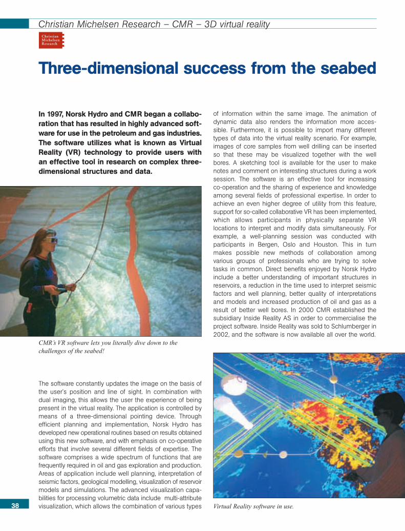
In 1997, Norsk Hydro and CMR began a collabo-ration that has resulted in highly advanced soft-ware for use in the petroleum and gas industries.The software utilizes what is known as VirtualReality (VR) technology to provide users withan effective tool in research on complex three-dimensional structures and data.
The software constantly updates the image on the basis ofthe user’s position and line of sight. In combination withdual imaging, this allows the user the experience of beingpresent in the virtual reality. The application is controlled bymeans of a three-dimensional pointing device. Throughefficient planning and implementation, Norsk Hydro hasdeveloped new operational routines based on results obtainedusing this new software, and with emphasis on co-operativeefforts that involve several different fields of expertise. Thesoftware comprises a wide spectrum of functions that arefrequently required in oil and gas exploration and production.Areas of application include well planning, interpretation ofseismic factors, geological modelling, visualization of reservoirmodels and simulations. The advanced visualization capa-bilities for processing volumetric data include multi-attributevisualization, which allows the combination of various types
of information within the same image. The animation ofdynamic data also renders the information more acces-sible. Furthermore, it is possible to import many differenttypes of data into the virtual reality scenario. For example,images of core samples from well drilling can be insertedso that these may be visualized together with the wellbores. A sketching tool is available for the user to makenotes and comment on interesting structures during a worksession. The software is an effective tool for increasing co-operation and the sharing of experience and knowledgeamong several fields of professional expertise. In order toachieve an even higher degree of utility from this feature,support for so-called collaborative VR has been implemented,which allows participants in physically separate VRlocations to interpret and modify data simultaneously. Forexample, a well-planning session was conducted withparticipants in Bergen, Oslo and Houston. This in turnmakes possible new methods of collaboration amongvarious groups of professionals who are trying to solvetasks in common. Direct benefits enjoyed by Norsk Hydroinclude a better understanding of important structures inreservoirs, a reduction in the time used to interpret seismicfactors and well planning, better quality of interpretationsand models and increased production of oil and gas as aresult of better well bores. In 2000 CMR established thesubsidiary Inside Reality AS in order to commercialise theproject software. Inside Reality was sold to Schlumberger in2002, and the software is now available all over the world.
Three-dimensional success from the seabed
38
Christian Michelsen Research – CMR – 3D virtual reality
Virtual Reality software in use.
CMR’s VR software lets you literally dive down to thechallenges of the seabed!
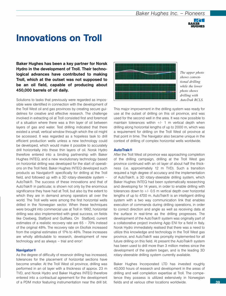
39
Baker Hughes Inc. – Pioneers
Baker Hughes has been a key partner for NorskHydro in the development of Troll. Their techno-logical advances have contributed to makingTroll, which at the outset was not supposed tobe an oil field, capable of producing about450,000 barrels of oil daily.
Solutions to tasks that previously were regarded as impos-sible were identified in connection with the development ofthe Troll West oil and gas provinces by creating secure gui-delines for creative and effective research. The challengeinvolved in extracting oil at Troll consisted first and foremostof a situation where there was a thin layer of oil betweenlayers of gas and water. Test drilling indicated that thereexisted a small, vertical window through which the oil mightbe accessed. It was regarded as a hopeless task to drillefficient production wells unless a new technology couldbe developed, which would make it possible to accuratelydrill horizontally into these thin layers of oil. Norsk Hydrotherefore entered into a binding partnership with BakerHughes INTEQ, and a new revolutionary technology basedon horizontal drilling was developed for the start of operati-ons on the Troll field. Baker Hughes INTEQ developed suchproducts as Navigator® specifically for drilling at the Trollfield, and followed up with a 3D rotary-steerable system –AutoTrak®. The success of these innovations and that ofAutoTrak® in particular, is shown not only by the enormoussignificance they have had at Troll, but also by the extent towhich they are in demand among operators all over theworld. The Troll wells were among the first horizontal wellsdrilled in the Norwegian sector. When these techniqueswere brought into commercial use at Troll in 1992, horizontaldrilling was also implemented with great success, on fieldslike Oseberg, Statfjord and Gullfaks. On Statfjord, currentestimates of a realistic recovery rate are 65 – 70% insteadof the original 48%. The recovery rate on Ekofisk increasedfrom the original estimates of 17% to 46%. These increasesare wholly attributable to research, development of newtechnology and as always – trial and error!
Navigator®As the degree of difficulty of reservoir drilling has increased,tolerances for the placement of horizontal sections havebecome smaller. At the Troll West oil province, drilling wasperformed in an oil layer with a thickness of approx. 23 mTVD, and Norsk Hydro and Baker Hughes INTEQ thereforeentered into a contractual agreement for the developmentof a PDM motor featuring instrumentation near the drill bit.
This major improvement in the drilling system was ready foruse at the outset of drilling on this oil province, and wasused for the second well in the area. It was now possible tomaintain tolerances within +/- 1 m vertical depth whendrilling along horizontal lengths of up to 2000 m, which wasa requirement for drilling on the Troll West oil province atthat point in time. The Navigator also became unique in thecontext of drilling of complex horizontal wells worldwide.
AutoTrak®After the Troll West oil province was approaching completionof the drilling campaign, drilling at the Troll West gasprovince continued with an oil layer of about half the thick-ness (i.e. approximately 12 m TVD). Such a transitionrequired a high degree of accuracy and the implementationof AutoTrak®, a 3D rotary-steerable drilling system, whichBaker Hughes INTEQ had been systematically researchingand developing for 14 years, in order to enable drilling withtolerances down to +/- 0.5 m vertical depth over horizontallengths of up to 4700 m. AutoTrak® is an intelligent drillingsystem with a two way communication link that enablesexecution of commands during drilling operations, in orderto correct direction and angle as well as receiving data atthe surface in real-time as the drilling progresses. Thedevelopment of the AutoTrak® system was originally part ofa collaborative project involving Agip ENI for a field in Italy.Norsk Hydro immediately realised that there was a need toutilize this knowledge and technology in the Troll West gasprovince, and AutoTrak® was promptly implemented for allfuture drilling on this field. At present the AutoTrak® systemhas been used to drill more than 3 million metres since thedevelopment of the system began, and is the leading 3Drotary-steerable drilling system currently available.
Baker Hughes Incorporated LTD has invested roughly40,000 hours of research and development in the areas ofdrilling and well completion expertise at Troll. The compe-tence they possess is utilized extensively in Norwegianfields and at various other locations worldwide.
Innovations on Troll
The upper photoshows conven-tional drillingwhile the lowerphoto showsdrilling withAutoTrak RCLS.
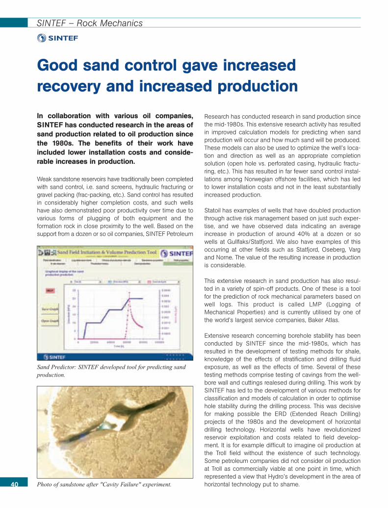
40
SINTEF – Rock Mechanics
In collaboration with various oil companies,SINTEF has conducted research in the areas ofsand production related to oil production sincethe 1980s. The benefits of their work haveincluded lower installation costs and conside-rable increases in production.
Weak sandstone reservoirs have traditionally been completedwith sand control, i.e. sand screens, hydraulic fracturing orgravel packing (frac-packing, etc.). Sand control has resultedin considerably higher completion costs, and such wellshave also demonstrated poor productivity over time due tovarious forms of plugging of both equipment and theformation rock in close proximity to the well. Based on thesupport from a dozen or so oil companies, SINTEF Petroleum
Research has conducted research in sand production sincethe mid-1980s. This extensive research activity has resultedin improved calculation models for predicting when sandproduction will occur and how much sand will be produced.These models can also be used to optimize the well’s loca-tion and direction as well as an appropriate completionsolution (open hole vs. perforated casing, hydraulic fractu-ring, etc.). This has resulted in far fewer sand control instal-lations among Norwegian offshore facilities, which has ledto lower installation costs and not in the least substantiallyincreased production.
Statoil has examples of wells that have doubled productionthrough active risk management based on just such exper-tise, and we have observed data indicating an averageincrease in production of around 40% at a dozen or sowells at Gullfaks/Statfjord. We also have examples of thisoccurring at other fields such as Statfjord, Oseberg, Vargand Norne. The value of the resulting increase in productionis considerable.
This extensive research in sand production has also resul-ted in a variety of spin-off products. One of these is a toolfor the prediction of rock mechanical parameters based onwell logs. This product is called LMP (Logging ofMechanical Properties) and is currently utilised by one ofthe world’s largest service companies, Baker Atlas.
Extensive research concerning borehole stability has beenconducted by SINTEF since the mid-1980s, which hasresulted in the development of testing methods for shale,knowledge of the effects of stratification and drilling fluidexposure, as well as the effects of time. Several of thesetesting methods comprise testing of cavings from the well-bore wall and cuttings realesed during drilling. This work bySINTEF has led to the development of various methods forclassification and models of calculation in order to optimisehole stability during the drilling process. This was decisivefor making possible the ERD (Extended Reach Drilling)projects of the 1980s and the development of horizontaldrilling technology. Horizontal wells have revolutionizedreservoir exploitation and costs related to field develop-ment. It is for example difficult to imagine oil production atthe Troll field without the existence of such technology.Some petroleum companies did not consider oil productionat Troll as commercially viable at one point in time, whichrepresented a view that Hydro’s development in the area ofhorizontal technology put to shame.
Good sand control gave increased recovery and increased production
Photo of sandstone after "Cavity Failure" experiment.
Sand Predictor: SINTEF developed tool for predicting sandproduction.
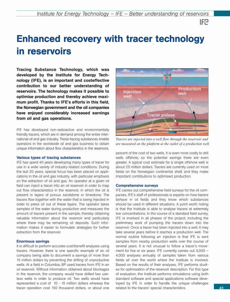
41
Institute for Energy Technology – IFE – Better understanding of reservoirs
Tracing Substance Technology, which wasdeveloped by the Institute for Energy Tech-nology (IFE), is an important and costeffectivecontribution to our better understanding ofreservoirs. The technology makes it possible tooptimise production and thereby achieve maxi-mum profit. Thanks to IFE’s efforts in this field,the Norwegian government and the oil companieshave enjoyed considerably increased earningsfrom oil and gas operations.
IFE has developed non-radioactive and environmentallyfriendly tracers, which are in demand among the entire inter-national oil and gas industry. These tracing substances enableoperators in the worldwide oil and gas business to obtainunique information about flow characteristics in the reservoirs.
Various types of tracing substancesIFE has spent 40 years developing many types of tracer foruse in a wide variety of industry-related conditions. Duringthe last 20 years, special focus has been placed on appli-cations in the oil and gas industry, with particular emphasison the extraction of oil and gas. An operator at a given oilfield can inject a tracer into an oil reservoir in order to mapout flow characteristics in the reservoir, in which the oil ispresent in layers of porous sandstone or limestone. Thetracers flow together with the water that is being injected inorder to press oil out of these layers. The operator takessamples of the water during production and measures theamount of tracers present in the sample, thereby obtainingvaluable information about the reservoir and particularlywhere there may be remaining oil deposits. Such infor-mation makes it easier to formulate strategies for furtherextraction from the reservoir.
Enormous savingsIt is difficult to perform accurate cost/benefit analyses usingtracers. However, there is one specific example of an oilcompany being able to document a savings of more than15 million dollars by preventing the drilling of unproductivewells. At a field in Columbia, BP used tracers from IFE in anoil reservoir. Without information obtained about blockagesin the reservoir, the company would have drilled two use-less wells in order to produce oil. Two wells would haverepresented a cost of 10 - 15 million dollars whereas thetracer operation cost 150 thousand dollars, or about one
percent of the cost of two wells. It is even more costly to drillwells offshore, so the potential savings there are evengreater. A typical cost estimate for a single offshore well isabout 25 million dollars. Tracers are currently used on mostfields on the Norwegian continental shelf, and they makeimportant contributions to optimised production.
Comprehensive surveysIFE carries out comprehensive field surveys for the oil com-panies. IFE’s staff of professionals is experts on how tracersbehave in oil fields and they know which substancesshould be used in different situations. A point worth notingis that the Institute is able to analyse tracers at extremelylow concentrations. In the course of a standard field survey,IFE is involved in all phases of the project, including thepreliminary work of pumping the tracers down into thereservoir. Once a tracer has been injected into a well, it maytake several years before it reaches a production well. Thenormal routine following an injection is that IFE is sentsamples from nearby production wells over the course ofseveral years. It is not unusual to follow a tracer’s move-ment for five or six years. IFE currently carries out 3,000 –4,000 analyses annually of samples taken from variousfields all over the world where the Institute is involved.Based on the results of their analyses, IFE performs studi-es for optimisation of the reservoir description. For this typeof evaluation, the Institute performs simulations using bothstandard software and special applications software deve-loped by IFE in order to handle the unique challengesrelated to the tracers’ special characteristics.
Enhanced recovery with tracer technologyin reservoirs
Tracers are injected into a well flow through the reservoir andare measured on the platform at the outlet of a production well.

42
SINTEF – Foam assisted water alternating gas injection – FAWAG
SINTEF has been involved in research concer-ning the use of foam in order to increase the oilrecovery during gas injection. The Instituterecommended the world’s largest foam injectionproject at the Snorre field, which resulted inincreased oil production to a value of about 35- 45 million dollars.
This technology has proved to be extremely successful,and has been tested on the Snorre field, among others. Aninjection mixture consisting of water with added surfactantand gas is used to control the flow of gas in the reservoir,leading to increased oil production. There is constant focusput on exploiting existing fields by further increasing therecoverable amount of oil and gas. Developments in theuse of foam have contributed accordingly. Water andsubsequently gas injection have also been successfullytested since production began at the Snorre field in 1992.In order to optimise the effects of the injected gas to aneven greater degree, research started early on the use offoam as a means of controlling the flow of injection gas inthe reservoir. This work resulted in several field pilots at theSnorre field in parallel with extensive research. SINTEFPetroleum Research participated in this process throughboth the RUTH and RESERVE research programs as well asprojects directly financed by the industry.
On the initiative of SINTEF Petroleum Research, the NorthSea’s first full scale testing of foam treatment FAWAG(foam assisted water alternating gas injection), began in
1996. A total of 3,000 tons of surfactant concentrate havebeen injected at the Snorre field and diluted with water,which has resulted in FAWAG being the world’s mostextensive foam injection project. The results of the foaminjection at the western fault block were extremely goodand included a considerable and enduring reduction ofbreakthrough gas produced. SINTEF Petroleum Researchhas participated in FAWAG through several projects, inclu-ding both laboratory-based testing of foam injection andsimulation studies aimed at predicting the effect of foam inthe reservoir. This prolonged activity was concluded in2000 with an evaluative study of FAWAG. The goal herewas to interpret the good results that had been achievedand to acquire a better understanding of how the foam hasfunctioned in the reservoir.
As a result of the FAWAG project, Saga Petroleum ASAreceived the Norwegian Petroleum Directorate’s IOR(Improved Oil Recovery) award in 1999. FAWAG is a goodexample of how collaboration involving industry, govern-mental authorities and research institutes can lead to thedevelopment and testing of new technologies in the field.
The FAWAG Project on the Snorre Field: • Injected surfactant: 380 m3 commercial mixture (38%)• Stored gas volume: 120 million Sm3
• Increased oil production: 210-250 000 Sm3
• Value of increased oil extraction: approximately 35 - 45 million dollars
• Increased oil production from other wells (due to gas-limited production at the field)
Foam improves recovery rates on Snorre
The FAWAG project at the Snorre field:Operating principle for foam treatment:Without foam most of the gas flows intothe high permeability layer. Foam treat-ment increases the flow resistance inthe high permeability layer to a relati-vely greater degree. The gas is forcedinto the less permeable layers and intocontact with new oil. The oil productionincreases and the production of break-through gas is reduced.
Yellow = OilOrange = Gas
Without FAWAG With FAWAG

43
Schlumberger – 4D Seismic Technology
3D seismic and horizontal wells are regarded byindustry experts as being two of the mostimportant innovations in the history of oil ope-rations ever. Schlumberger and WesternGecohave led the way for 3D seismic technologyfrom their respective research and developmentcentres right from the outset. Schlumbergerand WesternGeco currently invest nearly 100million dollars annually in research and deve-lopment in Norway.
Close cooperation between service and oil companies andNorwegian authorities resulted in Geco A/S being establishedin Oslo in 1972. Today, 32 years later, WesternGeco is theworld’s largest company specializing in seismic technology,and is led by Schlumberger and jointly owned with BakerHughes. 3D seismic technology has been vastly improved,and the latest innovation involves the introduction of "pro-duction time" as the fourth seismic dimension. So-called4D seismic or "time-lapse seismic" is used to monitor themovement of oil as it is being produced in a reservoir, similar
to the mapping of cloud system movements on a weathermap using time-lapse satellite measurements.
4D SeismologyTime-lapse measurements require exactly the same condi-tions during each recording of seismic data. "We muststeer the seismic sources to the same position, navigateeach recording line in the same direction and steer thethree-kilometre long receiver cables to exactly the samepositions," explains Schlumberger’s research director, LarsSønneland. In order to obtain such accuracy the vesselsmust tow seismic sources and seismic receiver cablesequipped with GPS satellite navigation and an acousticnetwork. The receiver cables are made steerable with thehelp of small wings, which function similar to aeroplanewings. This technology, developed by WesternGeco in Osloand manufactured in Knarvik near Bergen, has been extre-mely well received by customers around the world. It is theNorwegian oil companies Statoil and Norsk Hydro, whohave been worldwide leaders in terms of putting this new4D technology to use.
Time-lapse seismic provides oil companies with such accu-rate data that oil production can be increased considerably.
With time as the fourth dimension
3D seismic and horizontal wells are two of the most important innovations in the history of the oil industry, and research is stillbeing actively conducted in these areas. This year alone WesternGeco and Schlumberger will invest nearly $100 million inresearch and development in Norway. [Montage: Fasett A/S]
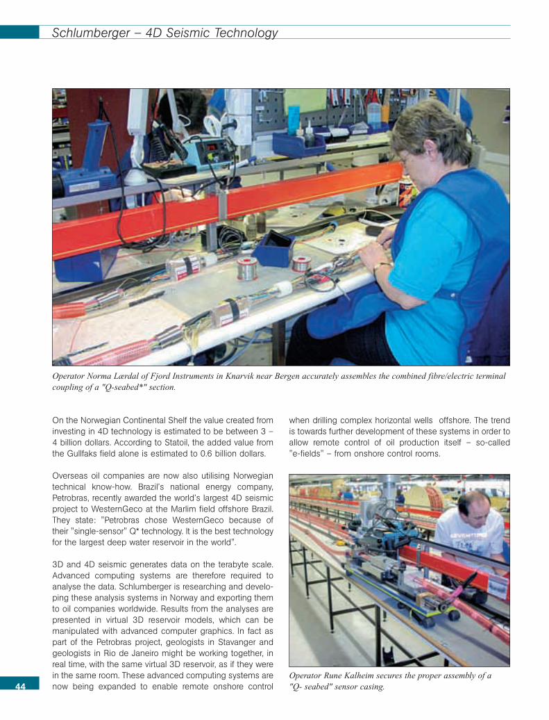
44
Schlumberger – 4D Seismic Technology
On the Norwegian Continental Shelf the value created frominvesting in 4D technology is estimated to be between 3 –4 billion dollars. According to Statoil, the added value fromthe Gullfaks field alone is estimated to 0.6 billion dollars.
Overseas oil companies are now also utilising Norwegiantechnical know-how. Brazil’s national energy company,Petrobras, recently awarded the world’s largest 4D seismicproject to WesternGeco at the Marlim field offshore Brazil.They state: "Petrobras chose WesternGeco because oftheir "single-sensor" Q* technology. It is the best technologyfor the largest deep water reservoir in the world".
3D and 4D seismic generates data on the terabyte scale.Advanced computing systems are therefore required toanalyse the data. Schlumberger is researching and develo-ping these analysis systems in Norway and exporting themto oil companies worldwide. Results from the analyses arepresented in virtual 3D reservoir models, which can bemanipulated with advanced computer graphics. In fact aspart of the Petrobras project, geologists in Stavanger andgeologists in Rio de Janeiro might be working together, inreal time, with the same virtual 3D reservoir, as if they werein the same room. These advanced computing systems arenow being expanded to enable remote onshore control
when drilling complex horizontal wells offshore. The trendis towards further development of these systems in order toallow remote control of oil production itself – so-called "e-fields" – from onshore control rooms.
Operator Norma Lærdal of Fjord Instruments in Knarvik near Bergen accurately assembles the combined fibre/electric terminalcoupling of a "Q-seabed*" section.
Operator Rune Kalheim secures the proper assembly of a "Q- seabed" sensor casing.

The development of the Troll field has receivedconsiderable attention from around the world.The gigantic project involved a variety of chal-lenges in which many research bodies wereasked to participate. The world’s tallest concrete platform is located in this field, in partthanks to SINTEF.
Based on its vast expertise, SINTEF helped make the so-called Condeep Platforms a reality. SINTEF made contri-butions in the form of concrete technology, methods for thecalculation of wave and current stress, construction tech-niques and calculation methods relating to foundation work.
TrollIn 1996, the enormous Troll gas field was opened. The world’stallest concrete platform is currently standing on the seabottom above the Troll gas deposits. Much of the research-based knowledge from SINTEF and NTNU is behind thework with this platform. The Troll platform is the last in along line of Condeep platforms that are placed on theNorwegian continental shelf. SINTEF/NTNU’s contributionto Condeep comprises many disciplines within engineering.
One of the tasks researchers were faced with was thedevelopment of a method for calculating wave and currentstress factors. This resulted in calculation tools that areused to calculate the behaviour and strength of the plat-forms as well as calculation methods that make it possibleto predict how the ground under the platforms will reactwhen the concrete blocks are positioned on the seabottom. The Troll platform is the tallest object ever movedby man. The 370 metre high concrete base would havetowered over the Eiffel Tower if it had been positioned in thecity centre of Paris, and it is constructed to withstandcurrents and wave stress in the exposed North Sea. Thiscolossus was build by Norwegian Contractors (now a partof Aker Kværner). The concrete used has greater strengthwhile also featuring lower weight than concrete that waspreviously used in offshore structures. SINTEF has contri-buted to this work by developing and documenting thematerial’s characteristics. Together with industry players,SINTEF/NTNU has also been involved in the developmentof the foundation solution, which actually made the Trollgiant possible in the first place. This development meansthat the Institutes now possess expertise concerningconcrete technology that has various applications relatingto numerous other projects and industries.
Gigantic Offshore Structures
46
SINTEF, Marintek – Development of new concrete technology
The Troll Platform – the tallest object ever moved by man.Photo: Norsk Hydro
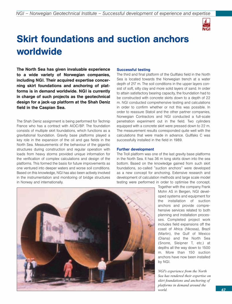
47
NGI – Norwegian Geotechnical Institute – Successful development of experience and expertise
The North Sea has given invaluable experienceto a wide variety of Norwegian companies,including NGI. Their acquired expertise concer-ning skirt foundations and anchoring of plat-forms is in demand worldwide. NGI is currentlyin charge of such projects as the geotechnicaldesign for a jack-up platform at the Shah Denizfield in the Caspian Sea.
The Shah Deniz assignment is being performed for TechnipFrance who has a contract with AIOC/BP. The foundationconsists of multiple skirt foundations, which functions as agravitational foundation. Gravity base platforms played akey role in the expansion of the oil and gas fields in theNorth Sea. Measurements of the behaviour of the giganticstructures during construction and regular operation withloads from heavy storms provided unique information forthe verification of complex calculations and design of theplatforms. This formed the basis for future improvements asone ventured into deeper waters and worse soil conditions. Based on this knowledge, NGI has also been actively involvedin the instrumentation and monitoring of bridge structuresin Norway and internationally.
Successful testingThe third and final platform of the Gullfaks field in the NorthSea is located towards the Norwegian trench at a waterdepth of 217 m. The soil conditions in the upper layers con-sist of soft, silty clay and more solid layers of sand. In orderto attain satisfactory bearing capacity, the foundation had tobe constructed with concrete skirts down to a depth of 22m. NGI conducted comprehensive testing and calculationsin order to confirm whether or not this was possible. Inorder to reassure Statoil and the other partner companies,Norwegian Contractors and NGI conducted a full-scalepenetration experiment out in the field. Two cylindersequipped with a concrete skirt were pressed down to 22 m.The measurement results corresponded quite well with thecalculations that were made in advance. Gullfaks C wassuccessfully installed in the field in 1989.
Further developmentThe Troll platform was one of the last gravity base platformsin the North Sea. It has 36 m long skirts down into the seabottom. Based on the knowledge gained from such skirtfoundations, so-called "suction anchors" were developedas a new concept for anchoring. Extensive research anddevelopment of calculation methods and large scale modeltesting were performed in order to optimise the concept.
Together with the company FrankMohn AS in Bergen, NGI devel-oped systems and equipment forthe installation of suctionanchors and provide compre-hensive services related to bothplanning and installation proces-ses. Completed project workincludes field expansions off thecoast of Africa (Nkossa), Brazil(Marlin), the Gulf of Mexico(Diana) and the North Sea(Snorre, Sleipner T, etc.) atdepths all the way down to 1500m. More than 150 suctionanchors have now been installedby NGI.
Skirt foundations and suction anchorsworldwide
NGI's experience from the NorthSea has rendered their expertise onskirt foundations and anchoring ofplatforms in demand around theworld.
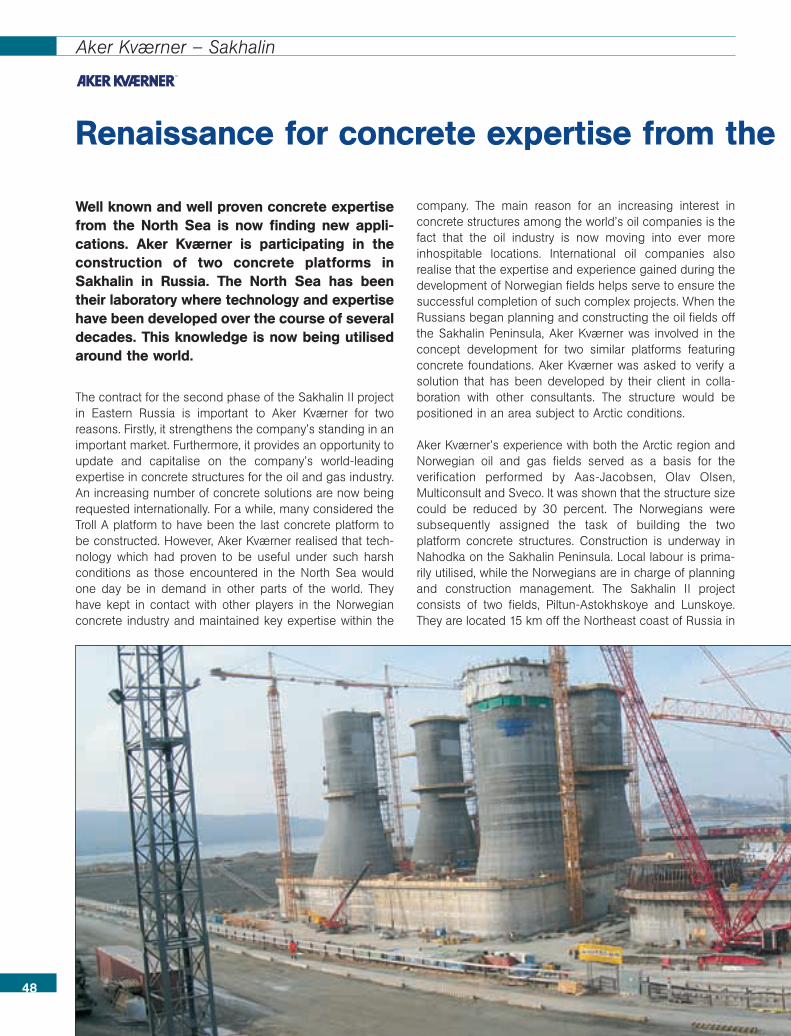
Renaissance for concrete expertise from the
48
Aker Kværner – Sakhalin
Well known and well proven concrete expertisefrom the North Sea is now finding new appli-cations. Aker Kværner is participating in theconstruction of two concrete platforms inSakhalin in Russia. The North Sea has beentheir laboratory where technology and expertisehave been developed over the course of severaldecades. This knowledge is now being utilisedaround the world.
The contract for the second phase of the Sakhalin II projectin Eastern Russia is important to Aker Kværner for tworeasons. Firstly, it strengthens the company’s standing in animportant market. Furthermore, it provides an opportunity toupdate and capitalise on the company’s world-leadingexpertise in concrete structures for the oil and gas industry.An increasing number of concrete solutions are now beingrequested internationally. For a while, many considered theTroll A platform to have been the last concrete platform tobe constructed. However, Aker Kværner realised that tech-nology which had proven to be useful under such harshconditions as those encountered in the North Sea wouldone day be in demand in other parts of the world. Theyhave kept in contact with other players in the Norwegianconcrete industry and maintained key expertise within the
company. The main reason for an increasing interest inconcrete structures among the world’s oil companies is thefact that the oil industry is now moving into ever moreinhospitable locations. International oil companies alsorealise that the expertise and experience gained during thedevelopment of Norwegian fields helps serve to ensure thesuccessful completion of such complex projects. When theRussians began planning and constructing the oil fields offthe Sakhalin Peninsula, Aker Kværner was involved in theconcept development for two similar platforms featuringconcrete foundations. Aker Kværner was asked to verify asolution that has been developed by their client in colla-boration with other consultants. The structure would bepositioned in an area subject to Arctic conditions.
Aker Kværner’s experience with both the Arctic region andNorwegian oil and gas fields served as a basis for theverification performed by Aas-Jacobsen, Olav Olsen,Multiconsult and Sveco. It was shown that the structure sizecould be reduced by 30 percent. The Norwegians weresubsequently assigned the task of building the twoplatform concrete structures. Construction is underway inNahodka on the Sakhalin Peninsula. Local labour is prima-rily utilised, while the Norwegians are in charge of planningand construction management. The Sakhalin II projectconsists of two fields, Piltun-Astokhskoye and Lunskoye.They are located 15 km off the Northeast coast of Russia in
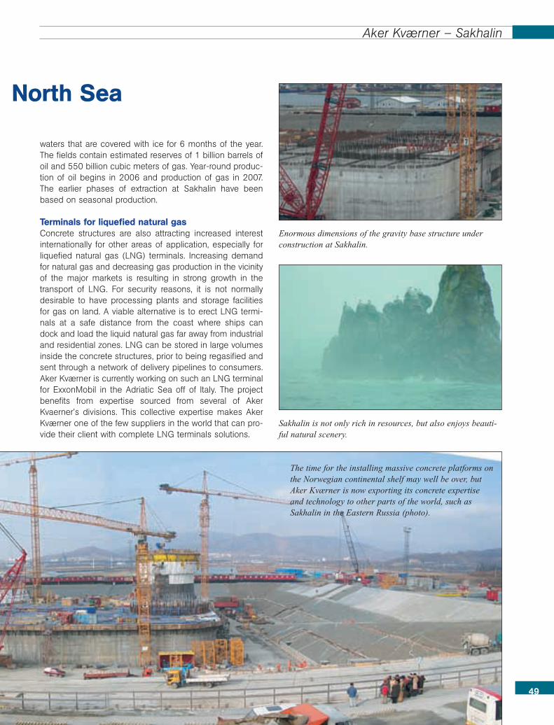
waters that are covered with ice for 6 months of the year.The fields contain estimated reserves of 1 billion barrels ofoil and 550 billion cubic meters of gas. Year-round produc-tion of oil begins in 2006 and production of gas in 2007.The earlier phases of extraction at Sakhalin have beenbased on seasonal production.
Terminals for liquefied natural gas Concrete structures are also attracting increased interestinternationally for other areas of application, especially forliquefied natural gas (LNG) terminals. Increasing demandfor natural gas and decreasing gas production in the vicinityof the major markets is resulting in strong growth in thetransport of LNG. For security reasons, it is not normallydesirable to have processing plants and storage facilitiesfor gas on land. A viable alternative is to erect LNG termi-nals at a safe distance from the coast where ships candock and load the liquid natural gas far away from industrialand residential zones. LNG can be stored in large volumesinside the concrete structures, prior to being regasified andsent through a network of delivery pipelines to consumers.Aker Kværner is currently working on such an LNG terminalfor ExxonMobil in the Adriatic Sea off of Italy. The projectbenefits from expertise sourced from several of AkerKvaerner’s divisions. This collective expertise makes AkerKværner one of the few suppliers in the world that can pro-vide their client with complete LNG terminals solutions.
49
North Sea
Aker Kværner – Sakhalin
The time for the installing massive concrete platforms onthe Norwegian continental shelf may well be over, butAker Kværner is now exporting its concrete expertiseand technology to other parts of the world, such asSakhalin in the Eastern Russia (photo).
Enormous dimensions of the gravity base structure underconstruction at Sakhalin.
Sakhalin is not only rich in resources, but also enjoys beauti-ful natural scenery.
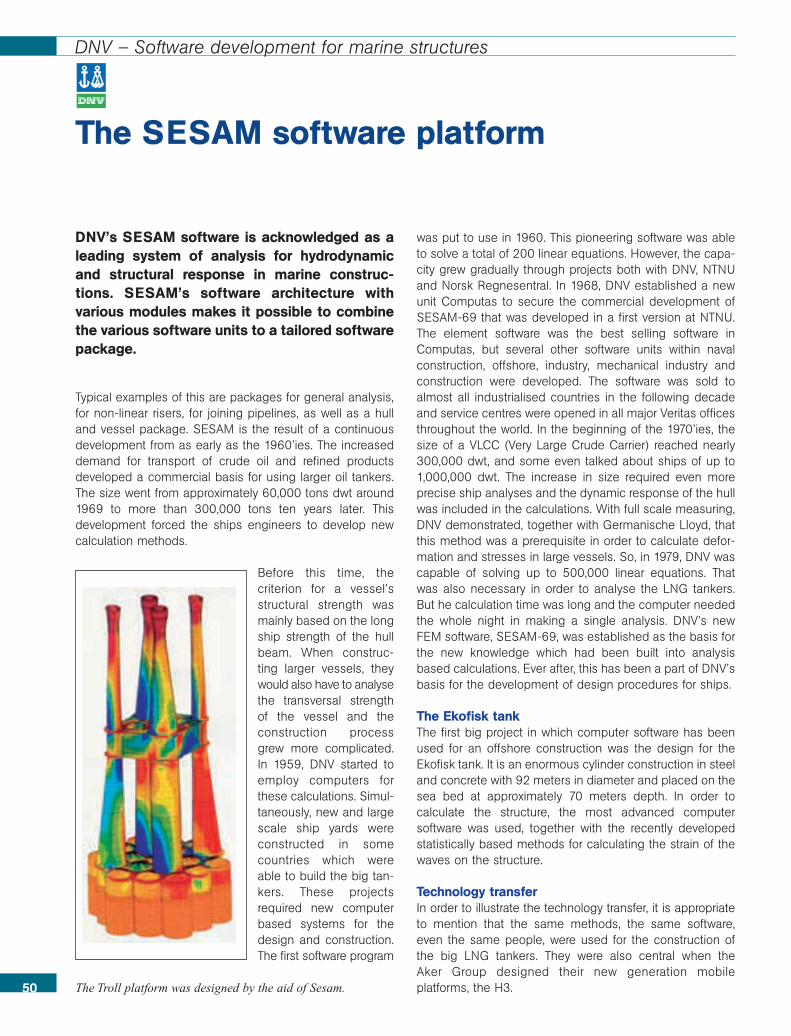
DNV’s SESAM software is acknowledged as aleading system of analysis for hydrodynamicand structural response in marine construc-tions. SESAM’s software architecture withvarious modules makes it possible to combinethe various software units to a tailored softwarepackage.
Typical examples of this are packages for general analysis,for non-linear risers, for joining pipelines, as well as a hulland vessel package. SESAM is the result of a continuousdevelopment from as early as the 1960’ies. The increaseddemand for transport of crude oil and refined productsdeveloped a commercial basis for using larger oil tankers.The size went from approximately 60,000 tons dwt around1969 to more than 300,000 tons ten years later. Thisdevelopment forced the ships engineers to develop newcalculation methods.
Before this time, thecriterion for a vessel’sstructural strength wasmainly based on the longship strength of the hullbeam. When construc-ting larger vessels, theywould also have to analysethe transversal strengthof the vessel and theconstruction processgrew more complicated.In 1959, DNV started toemploy computers forthese calculations. Simul-taneously, new and largescale ship yards wereconstructed in somecountries which wereable to build the big tan-kers. These projectsrequired new computerbased systems for thedesign and construction.The first software program
was put to use in 1960. This pioneering software was ableto solve a total of 200 linear equations. However, the capa-city grew gradually through projects both with DNV, NTNUand Norsk Regnesentral. In 1968, DNV established a newunit Computas to secure the commercial development ofSESAM-69 that was developed in a first version at NTNU.The element software was the best selling software inComputas, but several other software units within navalconstruction, offshore, industry, mechanical industry andconstruction were developed. The software was sold toalmost all industrialised countries in the following decadeand service centres were opened in all major Veritas officesthroughout the world. In the beginning of the 1970’ies, thesize of a VLCC (Very Large Crude Carrier) reached nearly300,000 dwt, and some even talked about ships of up to1,000,000 dwt. The increase in size required even moreprecise ship analyses and the dynamic response of the hullwas included in the calculations. With full scale measuring,DNV demonstrated, together with Germanische Lloyd, thatthis method was a prerequisite in order to calculate defor-mation and stresses in large vessels. So, in 1979, DNV wascapable of solving up to 500,000 linear equations. Thatwas also necessary in order to analyse the LNG tankers.But he calculation time was long and the computer neededthe whole night in making a single analysis. DNV’s newFEM software, SESAM-69, was established as the basis forthe new knowledge which had been built into analysisbased calculations. Ever after, this has been a part of DNV’sbasis for the development of design procedures for ships.
The Ekofisk tankThe first big project in which computer software has beenused for an offshore construction was the design for theEkofisk tank. It is an enormous cylinder construction in steeland concrete with 92 meters in diameter and placed on thesea bed at approximately 70 meters depth. In order tocalculate the structure, the most advanced computersoftware was used, together with the recently developedstatistically based methods for calculating the strain of thewaves on the structure.
Technology transferIn order to illustrate the technology transfer, it is appropriateto mention that the same methods, the same software,even the same people, were used for the construction ofthe big LNG tankers. They were also central when the Aker Group designed their new generation mobileplatforms, the H3.
The SESAM software platform
50
DNV – Software development for marine structures
The Troll platform was designed by the aid of Sesam.

51
DNV – Software development for marine structures
The finite element programs were essential tools! The nexttechnological break-through came in 1974 when the enor-mous concrete platforms, the Condeeps, were launched.The new generation SESAM system allowed for a selectionof modules. The non-linear modul FENRIS was based onsolving problems for which linear theory was inadequate.The software contained a special application for slim struc-tures with large displacements, such as, for example, marinerisers for oil production, and was also used for calculatingthe capacity of thin plate structures and complex shellstructures. The SESAM-80 project developed a new systemarchitecture on the basis of a large number of previousprojects that had been carried out by various Norwegianresearch institutes during the 1970’ies. The main reason fordevloping the new system was the need for more compre-hensive tools of analysis voiced by DNV. Structural analysiswas an essential component in Veritas’ work for making theships, the offshore installations and the industrial workplaces more safe and secure.
In 1985, the company VERITAS SESAM Systems AS wasfounded, and the software SESAM was launched on thebasis of the new system architecture as it had been defi-ned in the SESAM-80 project. SESAM Interface File (SIF)system had already been introduced and employed. Thiswas an important instrument for standardization of thecommunication between the pre-processor and the finiteelement software. The SIF format facilitated an integrationof the hydrodynamical software and the element softwarein SESAM and laid the foundation for automatic load trans-fer to the structure software. This made SESAM to acomplete and well arranged system of analysis. When thisextended version of SESAM had been in use for 18months, approximately 30 offshore jacket structures hadbeen analysed by means of the software. The analysis wereincorporated in a database which was designed to cover allthe platforms that were operated by the oil companies inthe North Sea.
In the late 1980’ies, DNV Research started a huge pro-gramme: Reliability of Marine Structures (RMS). The mainobjective of the project was to develop probabilistic calcu-lations of fatigue for jacket structures, anchored platformsand pipelines as well as a method for how to use theinspection results in order to estimate future damagecaused by fatigue. In 1994, the DNV started a projectsupported by Agip, Brown & Root and Tecnomare in orderto commercialize the software designed to estimate damage
by fatigue on jacket structures. The result was the proba-blitity based fatigue software PROFAST for inspectionplanning.
PROFAST is continually being further developed and is theinternational market leader in its area today. Through theyears, SESAM has continuously been developed by meansof new technology. In 1991, the basis for a new develop-ment phase was made with the working title SESAM-2000.DNV and its partners invested about 10 million US dollar ina new generation system architecture. The open architec-ture defined in the SESAM-2000 project was used in thedevelopment of a new pre-processor to the WADAM,named HydroD. Moreover, this facililitated an efficientconnection to various software modules relating to userinterface, load analysis, post processing of data and so on.
Heidrun-plattformen. Foto: Statoil.
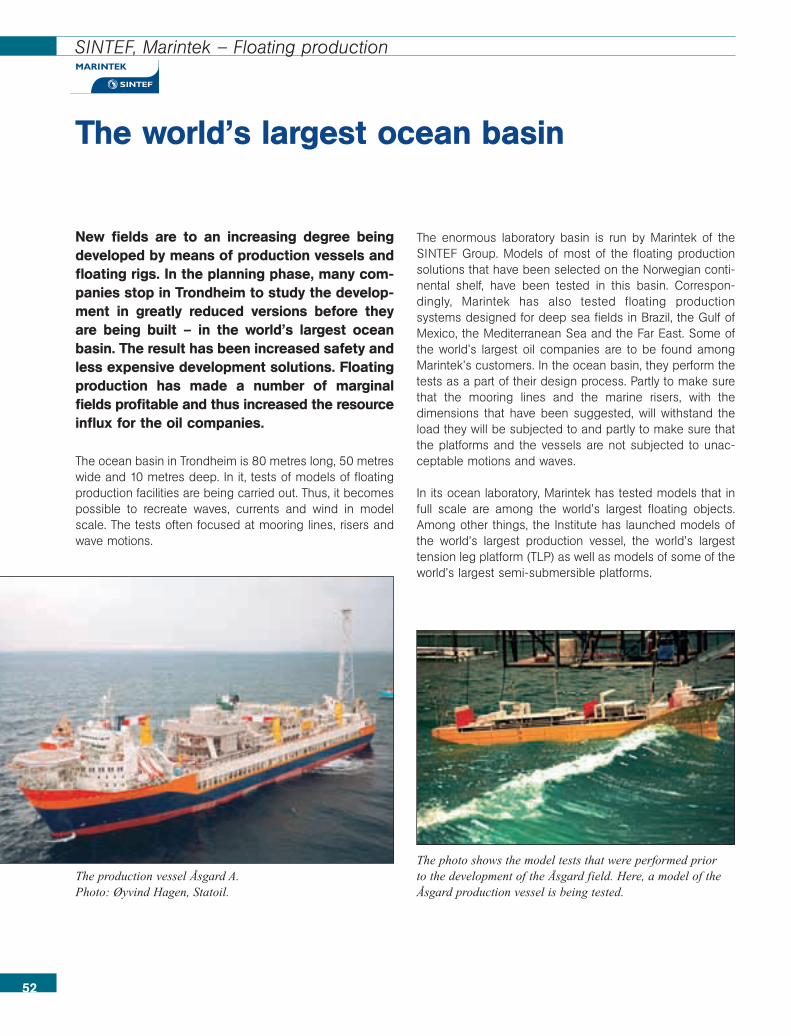
52
SINTEF, Marintek – Floating production
The world’s largest ocean basin
New fields are to an increasing degree beingdeveloped by means of production vessels andfloating rigs. In the planning phase, many com-panies stop in Trondheim to study the develop-ment in greatly reduced versions before theyare being built – in the world’s largest oceanbasin. The result has been increased safety andless expensive development solutions. Floatingproduction has made a number of marginalfields profitable and thus increased the resourceinflux for the oil companies.
The ocean basin in Trondheim is 80 metres long, 50 metreswide and 10 metres deep. In it, tests of models of floatingproduction facilities are being carried out. Thus, it becomespossible to recreate waves, currents and wind in modelscale. The tests often focused at mooring lines, risers andwave motions.
The enormous laboratory basin is run by Marintek of theSINTEF Group. Models of most of the floating productionsolutions that have been selected on the Norwegian conti-nental shelf, have been tested in this basin. Correspon-dingly, Marintek has also tested floating productionsystems designed for deep sea fields in Brazil, the Gulf ofMexico, the Mediterranean Sea and the Far East. Some ofthe world’s largest oil companies are to be found amongMarintek’s customers. In the ocean basin, they perform thetests as a part of their design process. Partly to make surethat the mooring lines and the marine risers, with thedimensions that have been suggested, will withstand theload they will be subjected to and partly to make sure thatthe platforms and the vessels are not subjected to unac-ceptable motions and waves.
In its ocean laboratory, Marintek has tested models that infull scale are among the world’s largest floating objects.Among other things, the Institute has launched models ofthe world’s largest production vessel, the world’s largesttension leg platform (TLP) as well as models of some of theworld’s largest semi-submersible platforms.
The photo shows the model tests that were performed prior to the development of the Åsgard field. Here, a model of theÅsgard production vessel is being tested.
The production vessel Åsgard A.Photo: Øyvind Hagen, Statoil.
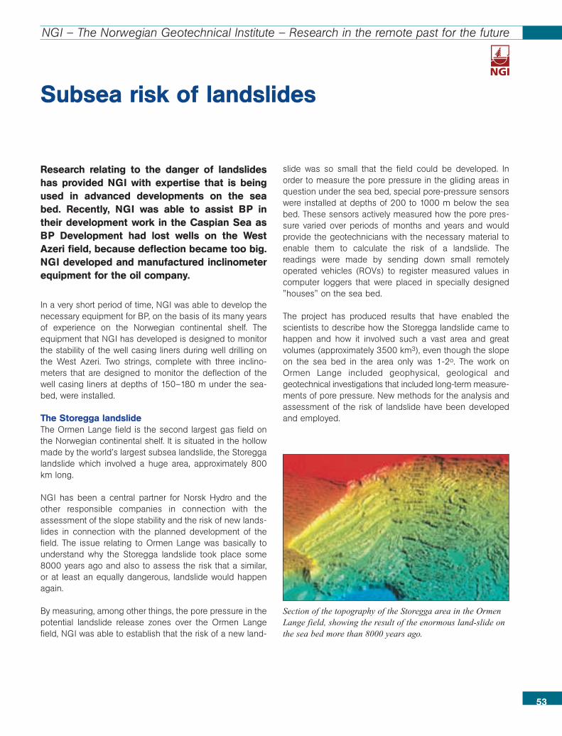
Research relating to the danger of landslideshas provided NGI with expertise that is beingused in advanced developments on the seabed. Recently, NGI was able to assist BP intheir development work in the Caspian Sea asBP Development had lost wells on the WestAzeri field, because deflection became too big.NGI developed and manufactured inclinometerequipment for the oil company.
In a very short period of time, NGI was able to develop thenecessary equipment for BP, on the basis of its many yearsof experience on the Norwegian continental shelf. Theequipment that NGI has developed is designed to monitorthe stability of the well casing liners during well drilling onthe West Azeri. Two strings, complete with three inclino-meters that are designed to monitor the deflection of thewell casing liners at depths of 150–180 m under the sea-bed, were installed.
The Storegga landslideThe Ormen Lange field is the second largest gas field onthe Norwegian continental shelf. It is situated in the hollowmade by the world’s largest subsea landslide, the Storeggalandslide which involved a huge area, approximately 800km long.
NGI has been a central partner for Norsk Hydro and theother responsible companies in connection with theassessment of the slope stability and the risk of new lands-lides in connection with the planned development of thefield. The issue relating to Ormen Lange was basically tounderstand why the Storegga landslide took place some8000 years ago and also to assess the risk that a similar,or at least an equally dangerous, landslide would happenagain.
By measuring, among other things, the pore pressure in thepotential landslide release zones over the Ormen Langefield, NGI was able to establish that the risk of a new land-
slide was so small that the field could be developed. Inorder to measure the pore pressure in the gliding areas inquestion under the sea bed, special pore-pressure sensorswere installed at depths of 200 to 1000 m below the seabed. These sensors actively measured how the pore pres-sure varied over periods of months and years and wouldprovide the geotechnicians with the necessary material toenable them to calculate the risk of a landslide. Thereadings were made by sending down small remotelyoperated vehicles (ROVs) to register measured values incomputer loggers that were placed in specially designed"houses" on the sea bed.
The project has produced results that have enabled thescientists to describe how the Storegga landslide came tohappen and how it involved such a vast area and greatvolumes (approximately 3500 km3), even though the slopeon the sea bed in the area only was 1-2o. The work onOrmen Lange included geophysical, geological andgeotechnical investigations that included long-term measure-ments of pore pressure. New methods for the analysis andassessment of the risk of landslide have been developedand employed.
53
NGI – The Norwegian Geotechnical Institute – Research in the remote past for the future
Subsea risk of landslides
Section of the topography of the Storegga area in the OrmenLange field, showing the result of the enormous land-slide onthe sea bed more than 8000 years ago.
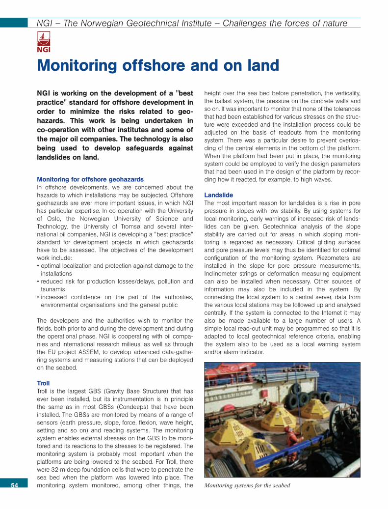
NGI is working on the development of a "bestpractice" standard for offshore development inorder to minimize the risks related to geo-hazards. This work is being undertaken in co-operation with other institutes and some ofthe major oil companies. The technology is alsobeing used to develop safeguards againstlandslides on land.
Monitoring for offshore geohazardsIn offshore developments, we are concerned about thehazards to which installations may be subjected. Offshoregeohazards are ever more important issues, in which NGIhas particular expertise. In co-operation with the Universityof Oslo, the Norwegian University of Science andTechnology, the University of Tromsø and several inter-national oil companies, NGI is developing a "best practice"standard for development projects in which geohazardshave to be assessed. The objectives of the developmentwork include:• optimal localization and protection against damage to the
installations• reduced risk for production losses/delays, pollution and
tsunamis• increased confidence on the part of the authorities,
environmental organisations and the general public
The developers and the authorities wish to monitor thefields, both prior to and during the development and duringthe operational phase. NGI is cooperating with oil compa-nies and international research milieus, as well as throughthe EU project ASSEM, to develop advanced data-gathe-ring systems and measuring stations that can be deployedon the seabed.
TrollTroll is the largest GBS (Gravity Base Structure) that hasever been installed, but its instrumentation is in principlethe same as in most GBSs (Condeeps) that have beeninstalled. The GBSs are monitored by means of a range ofsensors (earth pressure, slope, force, flexion, wave height,setting and so on) and reading systems. The monitoringsystem enables external stresses on the GBS to be moni-tored and its reactions to the stresses to be registered. Themonitoring system is probably most important when theplatforms are being lowered to the seabed. For Troll, therewere 32 m deep foundation cells that were to penetrate thesea bed when the platform was lowered into place. Themonitoring system monitored, among other things, the
height over the sea bed before penetration, the verticality,the ballast system, the pressure on the concrete walls andso on. It was important to monitor that none of the tolerancesthat had been established for various stresses on the struc-ture were exceeded and the installation process could beadjusted on the basis of readouts from the monitoringsystem. There was a particular desire to prevent overloa-ding of the central elements in the bottom of the platform.When the platform had been put in place, the monitoringsystem could be employed to verify the design parametersthat had been used in the design of the platform by recor-ding how it reacted, for example, to high waves.
LandslideThe most important reason for landslides is a rise in porepressure in slopes with low stability. By using systems forlocal monitoring, early warnings of increased risk of lands-lides can be given. Geotechnical analysis of the slopestability are carried out for areas in which sloping moni-toring is regarded as necessary. Critical gliding surfacesand pore pressure levels may thus be identified for optimalconfiguration of the monitoring system. Piezometers areinstalled in the slope for pore pressure measurements.Inclinometer strings or deformation measuring equipmentcan also be installed when necessary. Other sources ofinformation may also be included in the system. Byconnecting the local system to a central server, data fromthe various local stations may be followed up and analysedcentrally. If the system is connected to the Internet it mayalso be made available to a large number of users. Asimple local read-out unit may be programmed so that it isadapted to local geotechnical reference criteria, enablingthe system also to be used as a local warning systemand/or alarm indicator.
54
NGI – The Norwegian Geotechnical Institute – Challenges the forces of nature
Monitoring offshore and on land
Monitoring systems for the seabed
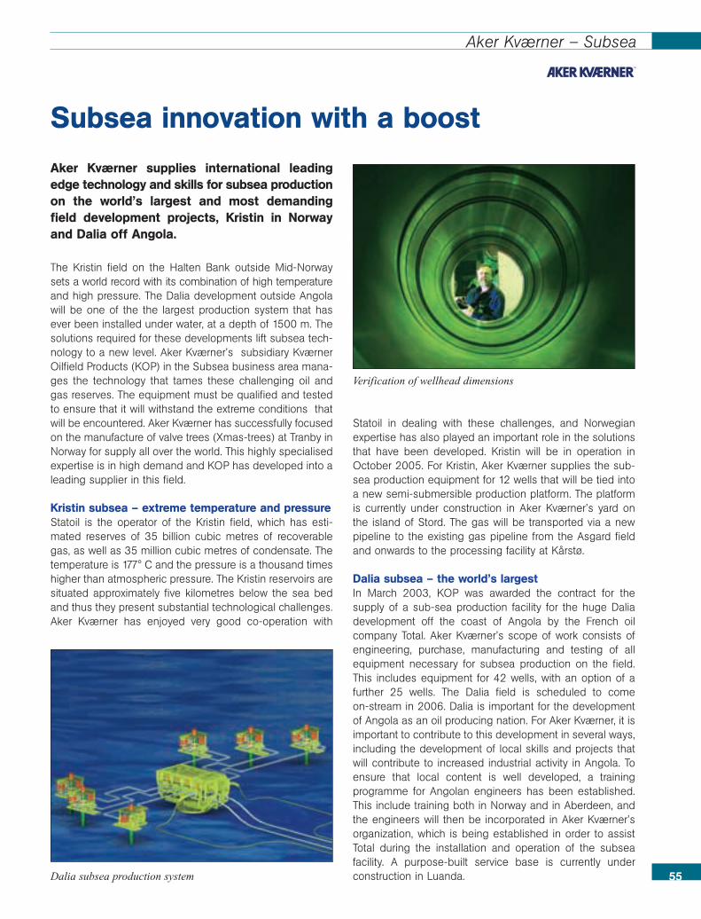
Aker Kværner supplies international leadingedge technology and skills for subsea productionon the world’s largest and most demandingfield development projects, Kristin in Norwayand Dalia off Angola.
The Kristin field on the Halten Bank outside Mid-Norwaysets a world record with its combination of high temperatureand high pressure. The Dalia development outside Angolawill be one of the the largest production system that hasever been installed under water, at a depth of 1500 m. Thesolutions required for these developments lift subsea tech-nology to a new level. Aker Kværner’s subsidiary KværnerOilfield Products (KOP) in the Subsea business area mana-ges the technology that tames these challenging oil andgas reserves. The equipment must be qualified and testedto ensure that it will withstand the extreme conditions thatwill be encountered. Aker Kværner has successfully focusedon the manufacture of valve trees (Xmas-trees) at Tranby inNorway for supply all over the world. This highly specialisedexpertise is in high demand and KOP has developed into aleading supplier in this field.
Kristin subsea – extreme temperature and pressureStatoil is the operator of the Kristin field, which has esti-mated reserves of 35 billion cubic metres of recoverablegas, as well as 35 million cubic metres of condensate. Thetemperature is 177° C and the pressure is a thousand timeshigher than atmospheric pressure. The Kristin reservoirs aresituated approximately five kilometres below the sea bedand thus they present substantial technological challenges.Aker Kværner has enjoyed very good co-operation with
Statoil in dealing with these challenges, and Norwegianexpertise has also played an important role in the solutionsthat have been developed. Kristin will be in operation inOctober 2005. For Kristin, Aker Kværner supplies the sub-sea production equipment for 12 wells that will be tied intoa new semi-submersible production platform. The platformis currently under construction in Aker Kværner’s yard onthe island of Stord. The gas will be transported via a newpipeline to the existing gas pipeline from the Asgard fieldand onwards to the processing facility at Kårstø.
Dalia subsea – the world’s largestIn March 2003, KOP was awarded the contract for thesupply of a sub-sea production facility for the huge Daliadevelopment off the coast of Angola by the French oilcompany Total. Aker Kværner’s scope of work consists ofengineering, purchase, manufacturing and testing of allequipment necessary for subsea production on the field.This includes equipment for 42 wells, with an option of afurther 25 wells. The Dalia field is scheduled to come on-stream in 2006. Dalia is important for the developmentof Angola as an oil producing nation. For Aker Kværner, it isimportant to contribute to this development in several ways,including the development of local skills and projects thatwill contribute to increased industrial activity in Angola. Toensure that local content is well developed, a trainingprogramme for Angolan engineers has been established.This include training both in Norway and in Aberdeen, andthe engineers will then be incorporated in Aker Kværner’sorganization, which is being established in order to assistTotal during the installation and operation of the subseafacility. A purpose-built service base is currently underconstruction in Luanda. 55
Aker Kværner – Subsea
Subsea innovation with a boost
Dalia subsea production system
Verification of wellhead dimensions

56
FMC Technologies – HOST
In response to the requirement to reduceproduction costs in the oil and gas industry,FMC decided to pursue standardization early inthe 1990s, when the company started thedevelopment of the very successful Hinge-OverSubsea Template (HOST) project. An individualHOST module weighs around 25 tonnes and aHOST base frame around 100 tonnes. Previously,a base frame would have weighed between 400and 600 tonnes. This story tells a little abouthow much less expensive it is to manufactureHOST, and how much easier it is to install.
The HOST project started in 1993. It is a fold-out subseabase frame complete with equipment. It was first introducedin 1994. When folded, a HOST may be passed through the"moonpool" of a floating drilling rig. The moonpool is thehole in the rig through which all work is done. When theHOST has been placed on the sea bed, it is folded out. Thesystem is very cost-effective because it may be constructedfrom standard elements. At the same time, it is also a veryflexible system. For this reason, it was developed further foruse at depths of up to 4,000 m. Statoil showed immediate
interest in the HOST idea and, in 1994, FMC and Statoil,signed a three-year agreement in which each party contri-buted more than 6 million US dollar to the developmentproject. Mobil joined as a partner early in 1995, and Elf andShell in October 1995.
Hand-drawn sketchHOST is a good example of how ingenious solutions areable to grow in environments where creativity thrives. Themanaging director of FMC, Tore Halvorsen, presented thevery first HOST project to Statoil by means of a simplehand-drawn sketch. The background for his idea for a baseframe that could be folded in and then out again was thenotion that it ought to be possible to use the rig for morethan the traditional purposes of such rigs.
Simple and inexpensiveDuring the installation of conventional subsea facilities,huge crane vessels have been necessary, and these areexpensive to operate. The modular HOST system, on theother hand, can be transported by supply vessels andhandled by the regular cranes on the rigs. As well as redu-cing costs, the HOST modular system provides a highdegree of flexibility. It is like a Lego system and may beadapted to an oil company’s particular range of field solu-
tions. The building blocks are thesame, irrespective of the projectinvolved, and are assembled insuch a way that they can be usedon any subsea field. FMC is thusable to customise solutions at an"off the shelf" price. HOST hasgiven FMC market opportunities farbeyond the North Sea, and there-fore it was very suitable for thecompany’s globalization strategy.
From hand-drawn sketch to technologicalsuccess
Installation of a HOST on the field.The wing elements have not yetbeen folded out after passagethrough the rig’s moonpool.
The oil companies will increasingly focus onsaving costs related to wells and well completion.Vecto has carried out a technological develop-ment programme that meets the need for cost-effective solutions for subsea developments indeep waters.
The system called NuDeepTM offers the potential for lowerinstallation and operating costs and is qualified and avai-lable on the market.
Well equipmentNuDeep TM has included the development of a compactwell-head system adapted to the industry’s increasing useof "slim and slender" well technology. There is a sharperfocus on the costs related to the use of rigs and installationvessels, and a great deal of work has been done on identi-fying methods in order to reduce time consumption. Oneexample is the installation of a valve tree with a separatevessel, or as a parallel operation from a rig, a measure thatis now being adopted in other regions. With the presenttechnology, in which a valve tree can typically weigh around40 tonnes, there will be handling restrictions (space andthe capacity of the lifting equipment). The equipment thathas been developed for well completion is called NuCompTM and consists of a super-light conventional valve tree(less than 17 tonnes), together with a ROV-operated tool to
pull and install TH plugs. The combination makes itpossible to plan batch completions and post-installations oftrees by wireline, thus improving the efficiency of rig utili-sation and saving considerable costs. The weight is so lowthat it can easily be handled from most rigs that operateglobally, as well as enabling it to be handled by a smallvessel (typically an anchor-handling vessel with an Aframe). The weight, together with arrangements for the useof "slim riser" technology, also means that the equipmentmay be installed in much deeper waters with a third-gene-ration rig, and thus it can help make considerable costsavings by avoiding having to mobilize a much moreexpensive fifth-generation rig. This is important for manyregions all over the world.
Manifolds and templatesThe typical solution for many regions around the world isthat of a set of satellite wells connected to a manifoldand/or the use of in-line Tees (typical for injection wells).But in the North Sea, the tradition is to use templates. Thereare many parameters that direct these choices and there-fore NuDeep TM (specifically NuFlow TM) is adapted toboth alternatives.
In the technology programme, the focus has been on deve-loping modules that are compact and that can be installedfrom typically small installation vessels (no module weighsmore than 65 tonnes). Emphasis has also been put on simpleconnection systems that do not require special runningtools, but that may be landed and connected simply by theuse of ROVs. The focus has been on inexpensive installation.This is achieved by the fact that the installation may beundertaken from a less expensive vessel and/or that theinstallation may be done as a parallel operation from the rig(typical for jumper installations).
Subsea processingThis is an area that has been on the agenda for manyyears, but in which the oil companies have not met theexpectations of the market as to the implementation andemployment of the technology. Although Troll Pilot was abig effort for Vecto, which has provided a lot of valuableexperience, no new units of this type have been installed orcommissioned.
In NuDeep TM, they concluded that the market needssomething more than Troll Oil and new and efficient sepa-ration technology has been developed to answer the needs 57
Vetco – NuDeep
Cost-effective subsea development
of the market. As more and more developments are carriedout in deep waters, a fact that will require more cost-effec-tive solutions, the need for subsea separation increases.Vecto therefore developed a compact light-weight subseaseparation module (NuProc TM) that is based on their ownseparation technology – coalescer. This technology offers aconsiderably smaller separator than standard technologyand provides solutions for separating oil with a low degreeof API combined with emulsion issues. The technology hasbeen qualified and demonstrated and contracts for testingthe separator on behalf of several oil companies have beensigned.
Control systemsThere are at least two challenges related to control systemsfor deep waters that have been addressed by NuDeep.Smaller valve trees require smaller control units and deeperwaters require simpler methods of repair. In order to getsmaller valve trees, it was important to reduce the size ofthe control module. It is not realistic to envisage fewer func-tions; rather the opposite. The solution, therefore, was todivide the functionality up into smaller modules, each ofwhich could be replaced by only an ROV and a standardtorque tool. Thus, a typical control system (NuTrols TM)which is offered as a part of the NuDeep TM programmeconsists of modules thatare connected by flyingleads, exchangeable byROV. This means that thecontrols of a valve tree or amanifold/template requireless space, less or nobalance weight and noinstallation guiding. Nor isa running tool required.Although this conceptentails more connections,availability analyses showthat availability has incre-ased thanks to reducedrepair time.58
Vecto – NuDeep
59
SINTEF, Marintek – SIMLA
As the world’s oil and gas industry moves toincreasing water depths, the limits of what isconsidered to be feasible are broken. Newtechnology develops rapidly, also at Marintek atSINTEF. Marintek has developed tools fordesign and planning of pipelaying operations(SIMLA) that are particularly useful at largewater depths. The gigantic Ormen Lange projectis one of the offshore field developments thathave gained from applying the new technology.
SIMLA is Marintek’s recently developed computer tool foranalysis of offshore pipelines, specially developed to dealwith problems related to deep waters and uneven seabed.SIMLA is able to simulate the installation of an offshorepipeline (laying analysis) while simultaneously taking intoaccount current and the true topography of the seabed. Theresults of the analysis can be inspected in a "virtual oceanspace" created by means of advanced 3D computer grap-hics in which the seabed is presented as a terrain modeltogether with the pipeline, and where the pipeline may beprovided with colour coding reflecting the type of analysisresult selected (for example stresses because of tension,external pressure and bending. Illustration: blue=compres-sion, red=tension).
One of the main challenges of the Ormen Lange projectwas to find routes for the pipelines from the reservoir areadirectly to Aukra in Møre and Romsdal. The pipelines are tobe laid through a subsea landslide area with a very rough
topography. In order to lay a pipeline through such an area,it is necessary to dig through a number of heaps and to fillin several hollows on the seabed. This is to avoid, as far aspossible, too long free spans along the pipeline route.Marintek’s unique tool SIMLA enabled Hydro to evaluate anumber of alternative pipeline routes, taking also intoaccount operational aspects during installation. SIMLA allo-wed the technical risks and the costs related to each alter-native to be assessed, so that Hydro was able to selectsafe and cost-optimal routes. SIMLA has recently been fur-ther developed and now also includes functionality for routeplanning and seabed intervention (dredging and rock dum-ping). New numerical methods for non-linear time domainanalysis and vessel control have also been introduced.Therefore, SIMLA has been a central tool for facilitatingsubsea to shore as a development concept for the OrmenLange field. The work of developing SIMLA has been fun-ded by Hydro and The Research Council of Norway (via theDEEPLINE Strategic Institute Programme). In all respects,this has been a useful and profitable investment for Hydro.
SIMLA facilitated Ormen Lange subsea to shore
SIMLA is unique in the world in the way that it simulatespipelaying with complex seabed topography.
DNV has more than 30 years experience withoffshore pipelines. The company’s “Rules forsubsea pipelines” appeared for the first time asearly as 1976. Today, DNV’s Offshore standardfor pipelines, first published in 1966, has becomean acknowledged standard for deep sub marinepipelines.
Today, the industry focuses first and foremost on costreduction and on improved safety standards. The result isinnovative design and construction methods. Simul-taneously, the industry faces new challenges in the form ofincreasingly deep waters, uneven sea bed, new materials,higher temperatures and pressure. The design of pipelinesis an important multi disciplinary task. It involves structuralanalysis, testing, fracture mechanics, material and corrosiontechnology, geotechnical assessments and hydro-dynamics. The costs of constructing a pipeline to newoffshore fields are often one of the main cost elements ofthe development as such. Thus it may be decisive for theeconomic analysis of the possibilities for developing thefield. Ever since 1999, DNV has invested in many researchprojects assessing a number of scenarios, including ultradeep waters, in order to develop reliable codes withconsistent safety levels; this is facilitating better designsand instalment of more cost effective pipelines offshore.
Superb ProjectThe ”Superb Project” established the foundation for relia-bility based design of pipelines. This project made thefoundation for DNV’s ”Rules for Submarine Pipelines” in1996, known in the industry as ”DNV ’96”. This was the firstpipe laying code based on a systematic structural reliabili-ty approach. It was taken further to a partial coefficientformat (”load and resistance factored” design format,LRFD), which introduced flexibility and made it possible forthe operators to design within a well defined and consistentsafety level and thus reduce costs. Sea bed intervention inconnection with pipelines is an important cost driver, parti-cularly in great depths and on uneven sea bed. With the
“Multi-span” project, a method for analysing vortex shed-ding and pipeline dynamics that may lead to fatigue forpipelines in free span, was at hand. The results have beencollected and converted to design guidelines for such pipe-lines. This facilitates performing extensive fatigue calcu-lations and assessments of pipelines rather than having toreduce the span lengths significantly. By permitting longerfree spans based on calibrated and well documentedanalysis, the costs of sea bed intervention are reduced.Today, deep water pipelines are laid with free spans of upto 200 meters, whereas previously, there was a maximumlength of 30 meters irrespective of environment and pipelaying conditions.
Corrosion in pipelinesThe service life of pipelines is often determined by corrosion.This is particularly true for fields with high temperatures andfields in which corrosive elements are present in the oil. Inthe project ”Functional stability in corroded pipelines”, acalculation method for the residual capacity of corrodedpipelines has been developed. This facilitates the re-quali-fication of the pipelines, which makes it possible for theoperator to define that a pipeline may be in operation withina defined safety margin in an extra number of years, evenafter changes in the operational conditions or observationof damage. Recent work within the project ”Fracture controlof installation methods for pipelines with cyclical plasticmoorings” has resulted in a guide for fracture mechanicstesting and calculation methods that are used for docu-menting sufficient resistance against fracture during instal-lation. The method provides considerable cost savingcompared to previous tests and calculation methods. A”Hotpipe” structural design guideline for pipelines for highpressure and high temperatures has also been prepared.DNV’s long term strategy of investing in and participating inresearch projects through three decades has given DNVwell respected, multi disciplinary expertise within pipelines.
Technical expertise with focus on safety
60
DNV – Offshore pipelines
Illustration of multispan
Test of pipelines in 1995
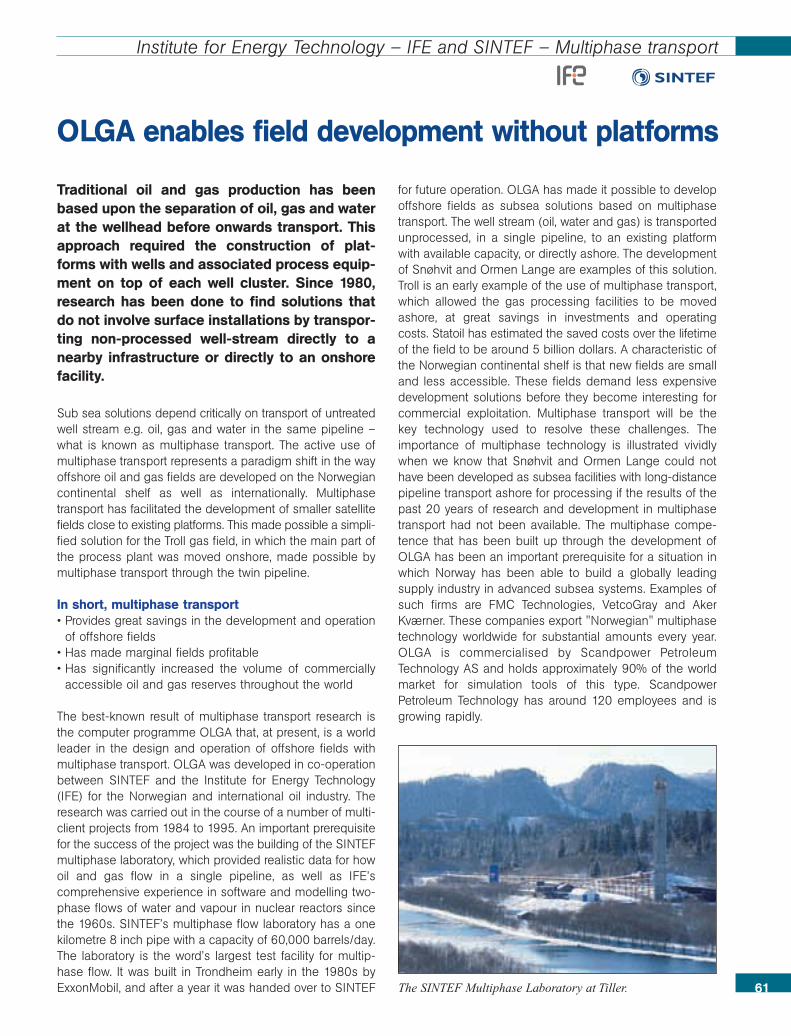
61
Institute for Energy Technology – IFE and SINTEF – Multiphase transport
Traditional oil and gas production has beenbased upon the separation of oil, gas and waterat the wellhead before onwards transport. Thisapproach required the construction of plat-forms with wells and associated process equip-ment on top of each well cluster. Since 1980,research has been done to find solutions thatdo not involve surface installations by transpor-ting non-processed well-stream directly to anearby infrastructure or directly to an onshorefacility.
Sub sea solutions depend critically on transport of untreatedwell stream e.g. oil, gas and water in the same pipeline –what is known as multiphase transport. The active use ofmultiphase transport represents a paradigm shift in the wayoffshore oil and gas fields are developed on the Norwegiancontinental shelf as well as internationally. Multiphasetransport has facilitated the development of smaller satellitefields close to existing platforms. This made possible a simpli-fied solution for the Troll gas field, in which the main part ofthe process plant was moved onshore, made possible bymultiphase transport through the twin pipeline.
In short, multiphase transport • Provides great savings in the development and operation
of offshore fields• Has made marginal fields profitable• Has significantly increased the volume of commercially
accessible oil and gas reserves throughout the world
The best-known result of multiphase transport research isthe computer programme OLGA that, at present, is a worldleader in the design and operation of offshore fields withmultiphase transport. OLGA was developed in co-operationbetween SINTEF and the Institute for Energy Technology(IFE) for the Norwegian and international oil industry. Theresearch was carried out in the course of a number of multi-client projects from 1984 to 1995. An important prerequisitefor the success of the project was the building of the SINTEFmultiphase laboratory, which provided realistic data for howoil and gas flow in a single pipeline, as well as IFE’scomprehensive experience in software and modelling two-phase flows of water and vapour in nuclear reactors sincethe 1960s. SINTEF’s multiphase flow laboratory has a onekilometre 8 inch pipe with a capacity of 60,000 barrels/day.The laboratory is the word’s largest test facility for multip-hase flow. It was built in Trondheim early in the 1980s byExxonMobil, and after a year it was handed over to SINTEF
for future operation. OLGA has made it possible to developoffshore fields as subsea solutions based on multiphasetransport. The well stream (oil, water and gas) is transportedunprocessed, in a single pipeline, to an existing platformwith available capacity, or directly ashore. The developmentof Snøhvit and Ormen Lange are examples of this solution.Troll is an early example of the use of multiphase transport,which allowed the gas processing facilities to be movedashore, at great savings in investments and operatingcosts. Statoil has estimated the saved costs over the lifetimeof the field to be around 5 billion dollars. A characteristic ofthe Norwegian continental shelf is that new fields are smalland less accessible. These fields demand less expensivedevelopment solutions before they become interesting forcommercial exploitation. Multiphase transport will be thekey technology used to resolve these challenges. Theimportance of multiphase technology is illustrated vividlywhen we know that Snøhvit and Ormen Lange could nothave been developed as subsea facilities with long-distancepipeline transport ashore for processing if the results of thepast 20 years of research and development in multiphasetransport had not been available. The multiphase compe-tence that has been built up through the development ofOLGA has been an important prerequisite for a situation inwhich Norway has been able to build a globally leadingsupply industry in advanced subsea systems. Examples ofsuch firms are FMC Technologies, VetcoGray and AkerKværner. These companies export "Norwegian" multiphasetechnology worldwide for substantial amounts every year.OLGA is commercialised by Scandpower PetroleumTechnology AS and holds approximately 90% of the worldmarket for simulation tools of this type. ScandpowerPetroleum Technology has around 120 employees and isgrowing rapidly.
OLGA enables field development without platforms
The SINTEF Multiphase Laboratory at Tiller.
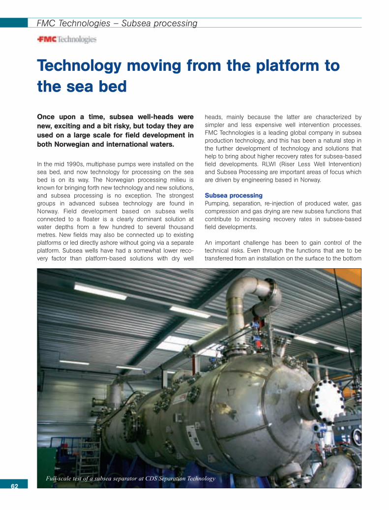
Once upon a time, subsea well-heads werenew, exciting and a bit risky, but today they areused on a large scale for field development inboth Norwegian and international waters.
In the mid 1990s, multiphase pumps were installed on thesea bed, and now technology for processing on the seabed is on its way. The Norwegian processing milieu isknown for bringing forth new technology and new solutions,and subsea processing is no exception. The strongestgroups in advanced subsea technology are found inNorway. Field development based on subsea wellsconnected to a floater is a clearly dominant solution atwater depths from a few hundred to several thousandmetres. New fields may also be connected up to existingplatforms or led directly ashore without going via a separateplatform. Subsea wells have had a somewhat lower reco-very factor than platform-based solutions with dry well
heads, mainly because the latter are characterized bysimpler and less expensive well intervention processes.FMC Technologies is a leading global company in subseaproduction technology, and this has been a natural step inthe further development of technology and solutions thathelp to bring about higher recovery rates for subsea-basedfield developments. RLWI (Riser Less Well Intervention)and Subsea Processing are important areas of focus whichare driven by engineering based in Norway.
Subsea processingPumping, separation, re-injection of produced water, gascompression and gas drying are new subsea functions thatcontribute to increasing recovery rates in subsea-basedfield developments.
An important challenge has been to gain control of thetechnical risks. Even through the functions that are to betransferred from an installation on the surface to the bottom
Technology moving from the platform tothe sea bed
62
FMC Technologies – Subsea processing
Full-scale test of a subsea separator at CDS Separation Technology

of the sea are well-known in their original form, there areother issues and priorities that have to be consideredsubsea. One consequence of equipment failure is longerdown times and more expensive repairs. This means thatdevelopment, testing and qualification are essential. FMCTechnologies has a tradition of teaming up with leadingNorwegian and foreign suppliers of technology to coverspecial needs outside of FMC’s core areas, and with thatas a starting point, to develop, test and qualify technologyand systems in co-operation with the operating companies.CDS Separation Technology is an example of this, whereCDS develops and supplies leading technology for thetopside market and FMC Technologies employs their know-ledge and technology as a basis for the part related to sub-sea separation.
Results provide opportunitiesSince the late 90s FMC Technologies has been developingtechnology and concepts for subsea processing. In 2004 itundertook a major qualifying project, in which a full-scalesubsea separation and sand handling system was develo-ped and tested in co-operation with Statoill, CDS and FMC.
DEMO 2000 and the Norne licence were involved in finan-cing the development. In addition, a number of importantcomponents needed in subsea systems have been deve-loped, tested and qualified. Foreign companies areshowing increasing interest in this technology as it falls intoplace, but most prefer to wait and see and to learn from thefirst installations that will probably come on the Norwegiancontinental shelf.
Future field developmentThere are many indicators that suggest that the future willneed increasingly advanced subsea technology, and thefuture is not too many years ahead. Today, we are conside-ring whether important gas fields like Ormen Lange andSnøhvit could produce without any kind of platform at all. Inorder to achieve this, technology and systems for subseagas compression must be in place. The industry is well onits way, and again Norwegian and international participantsmeet in Norway to develop new technology, because herethere are people, groups, resources and a milieu forinnovation and fresh thinking.
63
FMC Technologies – Subsea processing
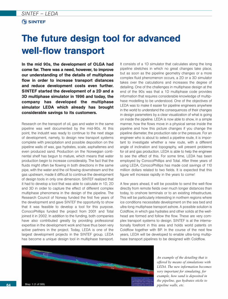
In the mid 90s, the development of OLGA hadcome far. There was a need, however, to improveour understanding of the details of multiphaseflow in order to increase transport distancesand reduce development costs even further.SINTEF started the development of a 2D and a3D multiphase simulator in 1996 and today, thecompany has developed the multiphasesimulator LEDA which already has broughtconsiderable savings to its customers.
Research on the transport of oil, gas and water in the samepipeline was well documented by the mid-90s. At thispoint, the industrt was ready to continue to the next stageof development, namely, to design new transport systemscomplete with precipitation and possible deposition on thepipeline walls of wax, gas hydrates, scale, asphaltenes andeven produced sand. Production on the Norwegian conti-nental shelf has begun to mature, which means that waterproduction begin to increase considerably. The fact that thefluids might often be flowing in both directions in the samepipe, with the water and the oil flowing downstream and thegas upstream, made it difficult to continue the developmentof design tools in only one dimension. SINTEF realized thatit had to develop a tool that was able to calculate in 1D, 2Dand 3D in order to capture the effect of different complexmultiphase phenomena in the design of the pipeline. TheResearch Council of Norway funded the first five years ofthe development and gave SINTEF the opportunity to showthat it was feasible to develop a tool for this purpose.ConocoPhillips funded the project from 2001 and Totaljoined it in 2002. In addition to the funding, both companieshave also contributed greatly by providing professionalexpertise in the development work and have thus been veryactive partners in the project. Today, LEDA is one of thelargest development projects in the SINTEF group. LEDAhas become a unique design tool in multiphase transport.
It consists of a 1D simulator that calculates along the longpipeline stretches in which no great changes take place,but as soon as the pipeline geometry changes or a morecomplex fluid phenomenon occurs, a 2D or a 3D simulatortakes over the calculations and increases the degree ofdetailing. One of the challenges in multiphase design at theend of the 90s was that a 1D multiphase code providesinformation that requires considerable knowledge of multip-hase modelling to be understood. One of the objectives ofLEDA was to make it easier for pipeline engineers anywherein the world to understand the consequences of their changesin design parameters by a clear visualization of what is goingon inside the pipeline. LEDA is now able to show, in a simplemanner, how the flows move in a physical sense inside thepipeline and how this picture changes if you change thepipeline diameter, the production rate or the pressure. For anengineer who is about to select a pipeline route, it is impor-tant to investigate whether a new route, with a differentangle of inclination and topography, will present problemsfor oil and gas production. LEDA is able to help the engineerto see the effect of this. For some time, LEDA has beenemployed by ConocoPhillips and Total. After three years ofusing LEDA, ConocoPhillips has made cost savings of 110million dollars related to two fields. It is expected that thisfigure will increase rapidly in the years to come!
A few years ahead, it will be possible to send the well-flowdirectly from remote fields over much longer distances thantoday, to onshore terminals or to an existing infrastructure.This will be particularly interesting in northern regions whereice conditions necessitate development on the sea bed andultra-long multiphase transport ashore. A possible solution isColdflow, in which gas hydrates and other solids at the well-head are formed and follow the flow. These are very com-plex transport systems to design. SINTEF is at the interna-tionally forefront in this area and holds world patents onColdflow together with BP. In the course of the next fewyears, LEDA will be developed to enable ultra-long multip-hase transport pipelines to be designed with Coldflow.
The future design tool for advanced well-flow transport
64
SINTEF – LEDA
An example of the detailing that isoffered by means of simulations withLEDA. The new information becomesvery important for simulating, forexample, how sand is deposited inthe pipeline, gas hydrates sticks topipeline walls, etc.
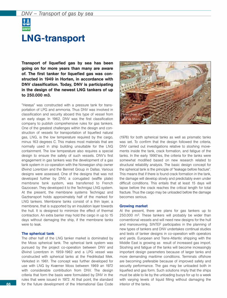
Transport of liquefied gas by sea has beengoing on for more years than many are awareof. The first tanker for liquefied gas was con-structed in 1949 in Horten, in accordance withDNV classification. Today, DNV is participatingin the design of the newest LNG tankers of upto 250.000 m3.
”Herøya” was constructed with a pressure tank for trans-portation of LPG and ammonia. Thus DNV was involved inclassification and security aboard this type of vessel froman early stage. In 1962, DNV was the first classificationcompany to publish comprehensive rules for gas tankers.One of the greatest challenges within the design and con-struction of vessels for transportation of liquefied naturalgas, LNG, is the low temperature required by the cargo,minus 163 degrees C. This makes most materials that arenormally used in ship building unsuitable for the LNGcontainment. The low temperature also requires a specialdesign to ensure the safety of such vessels. DNV’s firstengagement in gas tankers was the development of a gastank system in co-operation with the Norwegian ship ownerØivind Lorentzen and the Bennet Group in Dallas. Variousdesigns were assessed. One of the designs that was notdeveloped further by DNV, a corrugated (waffle plate)membrane tank system, was transferred to FrenchGazocean. They developed it to the Technigaz LNG system.At the present, the membrane systems Technigaz andGaztransport holds approximately half of the marked forLNG tankers. Membrane tanks consist of a thin layer, amembrane, that is supported by an insulation layer towardsthe hull. It is designed to minimize the effect of thermalcontraction. An extra barrier may hold the cargo in up to 15days without damaging the ship, if the membrane tankswere to leak.
The spherical tankThe other half of the LNG tanker market is dominated bythe Moss spherical tank. The spherical tank system waspursued by the project co-operation between DNV andØivind Lorentzen in 1959-1962 and a LPG vessel wasconstructed with spherical tanks at the Fredrikstad Mek.Verksted in 1961. The concept was further developed foruse with LNG by Kværner Moss between 1969 an 1972with considerable contribution from DNV. The designcriteria that form the basis were formulated by DNV in therules that were issued in 1972. At that point, the standardfor the future development of the International Gas Code
(1976) for both spherical tanks as well as prismatic tankswas set. To confirm that the design followed the criteria,DNV carried out investigations relative to sloshing move-ments inside the tank, crack formation, and fatigue of thetanks. In the early 1990’ies, the criteria for the tanks weresomewhat modified based on new research related tostructural reliability analysis. The basic design concept forthe spherical tank is the principle of “leakage before fracture”.This means that if there is found crack formation in the tank,the damage will develop slowly and predictably even underdifficult conditions. This entails that at least 15 days willlapse before the crack reaches the critical length for totalfracture. Thus the cargo may be unloaded before the damagebecomes serious.
Growing marketAt the present, there are plans for gas tankers up to250.000 m3. These tankers will probably be wider thanconventional vessels and will need new designs for the hulland manoeuvring. SINTEF participates in the planning ofnew types of tankers and DNV undertakes continual studiesand tests of tanker designs in co-operation with operatorsand yards. European and Trans-Atlantic shipping with theMiddle East is growing as result of increased gas import.Sloshing and fatigue of the tanks will become increasinglyimportant design parameters because of larger tanks andmore demanding maritime conditions. Terminals offshoreare becoming preferable because of improved safety andsecurity performance. The gas may be unloaded both inliquefied and gas form. Such solutions imply that the shipsmust be able to lie by the unloading buoys for up to a weekwith varying levels of liquid filling without damaging theinterior of the tanks.66
DNV – Transport of gas by sea
LNG-transport
Photo from the yard in Moss.
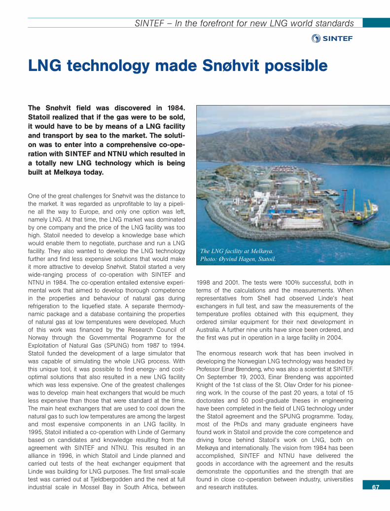
67
SINTEF – In the forefront for new LNG world standards
The Snøhvit field was discovered in 1984.Statoil realized that if the gas were to be sold,it would have to be by means of a LNG facilityand transport by sea to the market. The soluti-on was to enter into a comprehensive co-ope-ration with SINTEF and NTNU which resulted ina totally new LNG technology which is beingbuilt at Melkøya today.
One of the great challenges for Snøhvit was the distance tothe market. It was regarded as unprofitable to lay a pipeli-ne all the way to Europe, and only one option was left,namely LNG. At that time, the LNG market was dominatedby one company and the price of the LNG facility was toohigh. Statoil needed to develop a knowledge base whichwould enable them to negotiate, purchase and run a LNGfacility. They also wanted to develop the LNG technologyfurther and find less expensive solutions that would makeit more attractive to develop Snøhvit. Statoil started a verywide-ranging process of co-operation with SINTEF andNTNU in 1984. The co-operation entailed extensive experi-mental work that aimed to develop thorough competencein the properties and behaviour of natural gas duringrefrigeration to the liquefied state. A separate thermody-namic package and a database containing the propertiesof natural gas at low temperatures were developed. Muchof this work was financed by the Research Council ofNorway through the Governmental Programme for theExploitation of Natural Gas (SPUNG) from 1987 to 1994.Statoil funded the development of a large simulator thatwas capable of simulating the whole LNG process. Withthis unique tool, it was possible to find energy- and cost-optimal solutions that also resulted in a new LNG facilitywhich was less expensive. One of the greatest challengeswas to develop main heat exchangers that would be muchless expensive than those that were standard at the time.The main heat exchangers that are used to cool down thenatural gas to such low temperatures are among the largestand most expensive components in an LNG facility. In1995, Statoil initiated a co-operation with Linde of Germanybased on candidates and knowledge resulting from theagreement with SINTEF and NTNU. This resulted in analliance in 1996, in which Statoil and Linde planned andcarried out tests of the heat exchanger equipment thatLinde was building for LNG purposes. The first small-scaletest was carried out at Tjeldbergodden and the next at fullindustrial scale in Mossel Bay in South Africa, between
1998 and 2001. The tests were 100% successful, both interms of the calculations and the measurements. Whenrepresentatives from Shell had observed Linde’s heatexchangers in full test, and saw the measurements of thetemperature profiles obtained with this equipment, theyordered similar equipment for their next development inAustralia. A further nine units have since been ordered, andthe first was put in operation in a large facility in 2004.
The enormous research work that has been involved indeveloping the Norwegian LNG technology was headed byProfessor Einar Brendeng, who was also a scientist at SINTEF.On September 19, 2003, Einar Brendeng was appointedKnight of the 1st class of the St. Olav Order for his pionee-ring work. In the course of the past 20 years, a total of 15doctorates and 50 post-graduate theses in engineeringhave been completed in the field of LNG technology underthe Statoil agreement and the SPUNG programme. Today,most of the PhDs and many graduate engineers havefound work in Statoil and provide the core competence anddriving force behind Statoil’s work on LNG, both onMelkøya and internationally. The vision from 1984 has beenaccomplished, SINTEF and NTNU have delivered thegoods in accordance with the agreement and the resultsdemonstrate the opportunities and the strength that arefound in close co-operation between industry, universitiesand research institutes.
LNG technology made Snøhvit possible
The LNG facility at Melkøya. Photo: Øyvind Hagen, Statoil.
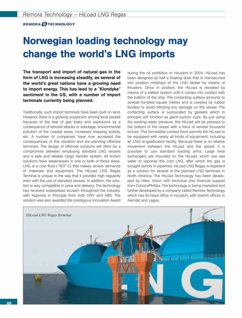
68
Remora Technology – HiLoad LNG Regas
Norwegian loading technology maychange the world’s LNG imports
HiLoad LNG Regas Terminal
The transport and import of natural gas in theform of LNG is increasing steadily, as several ofthe world’s great nations have a growing needto import energy. This has lead to a "Klondyke"sentiment in the US, with a number of importterminals currently being planned.
Traditionally, such import terminals have been built on land.However, there is a growing scepticism among local peoplebecause of the fear of gas leaks and explosions as aconsequence of terrorist attacks or sabotage, environmentalpollution of the coastal areas, increased shipping activity,etc. A number of companies have now accepted theconsequences of this situation and are planning offshoreterminals. The design of offshore solutions will often be acompromise between employing standard LNG vesselsand a safe and reliable cargo transfer system. All knownsolutions have weaknesses in one or both of these areas.LNG is a cold fluid (-163° C) that makes severe demandsof materials and equipment. The HiLoad LNG RegasTerminal is unique in the way that it provides high regularityeven with the use of standard vessels. In addition, the solu-tion is very competitive in price and delivery. The technologyhas received widespread acclaim throughout the industry,with Approval in Principle from both DNV and ABS. Thesolution was also awarded the prestigious Innovation Award
during the oil exhibition in Houston in 2004. HiLoad hasbeen designed as half a floating dock that is manoeuvredinto position midships of the LNG tanker by means ofthrusters. Once in position, the HiLoad is elevated bymeans of a ballast system until it comes into contact withthe bottom of the ship. The contacting surface amounts toseveral hundred square metres and is covered by rubberfenders to avoid inflicting any damage on the vessel. Thecontacting surface is surrounded by gaskets which inprinciple will function as giant suction cups. By just usingthe existing water pressure, the HiLoad will be pressed tothe bottom of the vessel with a force of several thousandtonnes. This formidable contact force permits the HiLoad tobe equipped with nearly all kinds of equipment, includingan LNG re-gasification facility. Because there is no relativemovement between the HiLoad and the vessel, it ispossible to use standard loading arms. Large heatexchangers are mounted on the HiLoad, which use seawater to vaporise the cold LNG, after which the gas isbrought ashore in pipelines. HiLoad LNG Regas is regardedas a solution for several of the planned LNG terminals inNorth America. The HiLoad Technology has been develo-ped by Hitec Vision with technical and financial supportfrom ConocoPhillips. The technology is being marketed andfurther developed by a company called Remora Technologywhich has its head office in Houston, with branch offices inArendal and Lagos.
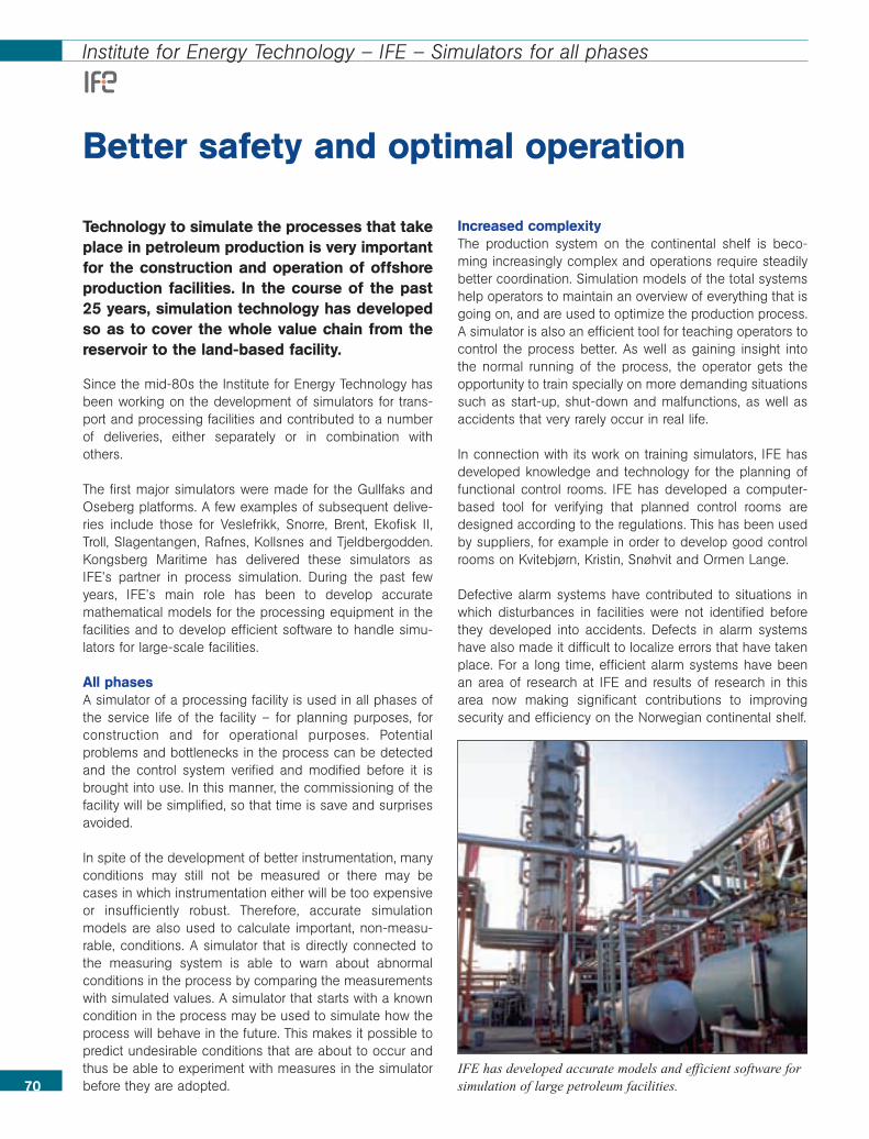
70
Institute for Energy Technology – IFE – Simulators for all phases
Technology to simulate the processes that takeplace in petroleum production is very importantfor the construction and operation of offshoreproduction facilities. In the course of the past25 years, simulation technology has developedso as to cover the whole value chain from thereservoir to the land-based facility.
Since the mid-80s the Institute for Energy Technology hasbeen working on the development of simulators for trans-port and processing facilities and contributed to a numberof deliveries, either separately or in combination withothers.
The first major simulators were made for the Gullfaks andOseberg platforms. A few examples of subsequent delive-ries include those for Veslefrikk, Snorre, Brent, Ekofisk II,Troll, Slagentangen, Rafnes, Kollsnes and Tjeldbergodden.Kongsberg Maritime has delivered these simulators asIFE’s partner in process simulation. During the past fewyears, IFE’s main role has been to develop accuratemathematical models for the processing equipment in thefacilities and to develop efficient software to handle simu-lators for large-scale facilities.
All phasesA simulator of a processing facility is used in all phases ofthe service life of the facility – for planning purposes, forconstruction and for operational purposes. Potentialproblems and bottlenecks in the process can be detectedand the control system verified and modified before it isbrought into use. In this manner, the commissioning of thefacility will be simplified, so that time is save and surprisesavoided.
In spite of the development of better instrumentation, manyconditions may still not be measured or there may becases in which instrumentation either will be too expensiveor insufficiently robust. Therefore, accurate simulationmodels are also used to calculate important, non-measu-rable, conditions. A simulator that is directly connected tothe measuring system is able to warn about abnormalconditions in the process by comparing the measurementswith simulated values. A simulator that starts with a knowncondition in the process may be used to simulate how theprocess will behave in the future. This makes it possible topredict undesirable conditions that are about to occur andthus be able to experiment with measures in the simulatorbefore they are adopted.
Increased complexityThe production system on the continental shelf is beco-ming increasingly complex and operations require steadilybetter coordination. Simulation models of the total systemshelp operators to maintain an overview of everything that isgoing on, and are used to optimize the production process.A simulator is also an efficient tool for teaching operators tocontrol the process better. As well as gaining insight intothe normal running of the process, the operator gets theopportunity to train specially on more demanding situationssuch as start-up, shut-down and malfunctions, as well asaccidents that very rarely occur in real life.
In connection with its work on training simulators, IFE hasdeveloped knowledge and technology for the planning offunctional control rooms. IFE has developed a computer-based tool for verifying that planned control rooms aredesigned according to the regulations. This has been usedby suppliers, for example in order to develop good controlrooms on Kvitebjørn, Kristin, Snøhvit and Ormen Lange.
Defective alarm systems have contributed to situations inwhich disturbances in facilities were not identified beforethey developed into accidents. Defects in alarm systemshave also made it difficult to localize errors that have takenplace. For a long time, efficient alarm systems have beenan area of research at IFE and results of research in thisarea now making significant contributions to improvingsecurity and efficiency on the Norwegian continental shelf.
Better safety and optimal operation
IFE has developed accurate models and efficient software forsimulation of large petroleum facilities.
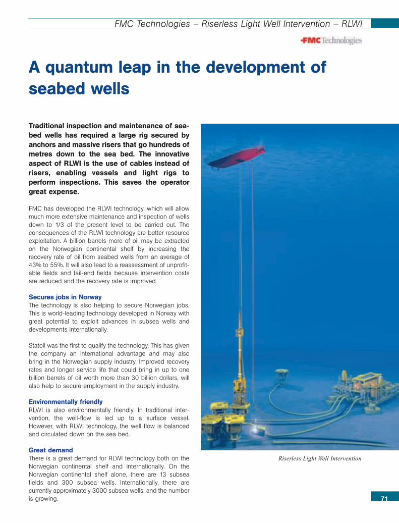
71
FMC Technologies – Riserless Light Well Intervention – RLWI
Traditional inspection and maintenance of sea-bed wells has required a large rig secured byanchors and massive risers that go hundreds ofmetres down to the sea bed. The innovativeaspect of RLWI is the use of cables instead ofrisers, enabling vessels and light rigs toperform inspections. This saves the operatorgreat expense.
FMC has developed the RLWI technology, which will allowmuch more extensive maintenance and inspection of wellsdown to 1/3 of the present level to be carried out. Theconsequences of the RLWI technology are better resourceexploitation. A billion barrels more of oil may be extractedon the Norwegian continental shelf by increasing therecovery rate of oil from seabed wells from an average of43% to 55%. It will also lead to a reassessment of unprofit-able fields and tail-end fields because intervention costsare reduced and the recovery rate is improved.
Secures jobs in NorwayThe technology is also helping to secure Norwegian jobs.This is world-leading technology developed in Norway withgreat potential to exploit advances in subsea wells anddevelopments internationally.
Statoil was the first to qualify the technology. This has giventhe company an international advantage and may alsobring in the Norwegian supply industry. Improved recoveryrates and longer service life that could bring in up to onebillion barrels of oil worth more than 30 billion dollars, willalso help to secure employment in the supply industry.
Environmentally friendlyRLWI is also environmentally friendly. In traditional inter-vention, the well-flow is led up to a surface vessel.However, with RLWI technology, the well flow is balancedand circulated down on the sea bed.
Great demandThere is a great demand for RLWI technology both on theNorwegian continental shelf and internationally. On theNorwegian continental shelf alone, there are 13 subseafields and 300 subsea wells. Internationally, there arecurrently approximately 3000 subsea wells, and the numberis growing.
A quantum leap in the development ofseabed wells
Riserless Light Well Intervention
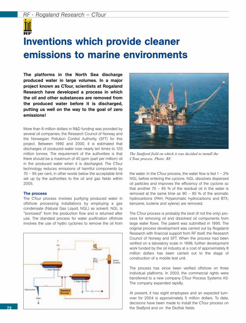
The platforms in the North Sea dischargeproduced water in large volumes. In a majorproject known as CTour, scientists at RogalandResearch have developed a process in whichthe oil and other substances are removed fromthe produced water before it is discharged,putting us well on the way to the goal of zeroemissions!
More than 8 million dollars in R&D funding was provided byseveral oil companies, the Research Council of Norway andthe Norwegian Pollution Control Authority (SFT) for thisproject. Between 1990 and 2000, it is estimated thatdischarges of produced water rose nearly ten times to 120million tonnes. The requirement of the authorities is thatthere should be a maximum of 40 ppm (part per million) oilin the produced water when it is discharged. The CTourtechnology reduces emissions of harmful components by70 – 95 per cent, in other words below the acceptable limitset up by the authorities to the oil and gas fields within2005.
The process The CTour process involves purifying produced water inoffshore processing installations by employing a gascondensate (Natural Gas Liquid, NGL) as solvent. NGL is"borrowed" from the production flow and is returned afteruse. The standard process for water purification offshoreinvolves the use of hydro cyclones to remove the oil from
the water. In the CTour process, the water flow is fed 1 – 2%NGL before entering the cyclone. NGL dissolves dispersedoil particles and improves the efficiency of the cyclone sothat another 70 – 95 % of the residual oil in the water isremoved at the same time as 90 – 95 % of the aromatichydrocarbons (PAH; Polyaromatic hydrocarbons and BTX;benzene, tuolene and xylene) are removed.
The CTour process is probably the best (if not the only) pro-cess for removing oil and dissolved oil components fromlarge water flows. The patent was submitted in 1995. Theoriginal process development was carried out by RogalandResearch with financial support from RF itself, the ResearchCouncil of Norway and SFT. When the process had beenverified on a laboratory scale in 1998, further developmentwork funded by the oil industry at a cost of approximately 8million dollars has been carried out to the stage ofconstruction of a mobile test unit.
The process has since been verified offshore on threeindividual platforms. In 2003, the commercial rights weretransferred to a new company CTour Process Systems AS:The company expanded rapidly.
At present, it has eight employees and an expected turn-over for 2004 is approximately 5 million dollars. To date,decisions have been made to install the CTour process onthe Statfjord and on the Ekofisk fields.72
RF - Rogaland Research – CTour
Inventions which provide cleaneremissions to marine environments
The Statfjord field on which it was decided to install theCTour process. Photo: RF.
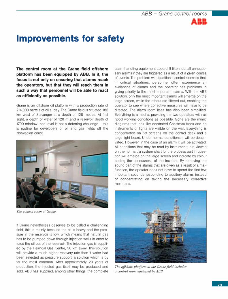
73
ABB – Grane control rooms
The control room at the Grane field offshoreplatform has been equipped by ABB. In it, thefocus is not only on ensuring that alarms reachthe operators, but that they will reach them insuch a way that personnel will be able to reactas efficiently as possible.
Grane is an offshore oil platform with a production rate of214,000 barrels of oil a day. The Grane field is situated 185km west of Stavanger at a depth of 128 metres. At firstsight, a depth of water of 128 m and a reservoir depth of1700 mbelow sea level is not a deterring challenge – thisis routine for developers of oil and gas fields off theNorwegian coast.
If Grane nevertheless deserves to be called a challengingfield, this is mainly because the oil is heavy and the pres-sure in the reservoir is low, which means that natural gashas to be pumped down through injection wells in order toforce the oil out of the reservoir. The injection gas is suppli-ed by the Heimdal Gas Centre, 50 km away. This solutionwill provide a much higher recovery rate than if water hadbeen selected as pressure support, a solution which is byfar the most common. After approximately 20 years ofproduction, the injected gas itself may be produced andsold. ABB has supplied, among other things, the complete
alarm handling equipment aboard. It filters out all unneces-sary alarms if they are triggered as a result of a given courseof events. The problem with traditional control rooms is that,in critical situations, personnel often experience anavalanche of alarms and the operator has problems ingiving priority to the most important alarms. With the ABBsolution, only the most important alarms will emerge on thelarge screen, while the others are filtered out, enabling theoperator to see where corrective measures will have to bedirected. The alarm room itself has also been simplified.Everything is aimed at providing the two operators with asgood working conditions as possible. Gone are the mimicdiagrams that look like decorated Christmas trees and noinstruments or lights are visible on the wall. Everything isconcentrated on flat screens on the control desk and alarge light board. Under normal conditions it will be deacti-vated. However, in the case of an alarm it will be activated.All conditions that may be read by instruments are viewedon the normal , a system chart for the process part in ques-tion will emerge on the large screen and indicate by colourcoding the seriousness of the incident. By removing thesound part of the alarms that are given as a result of a mal-function, the operator does not have to spend the first fewimportant seconds responding to auditory alarms insteadof concentrating on taking the necessary correctivemeasures.
Improvements for safety
The control room at Grane.
The offshore platform at the Grane field includesa control room equipped by ABB.
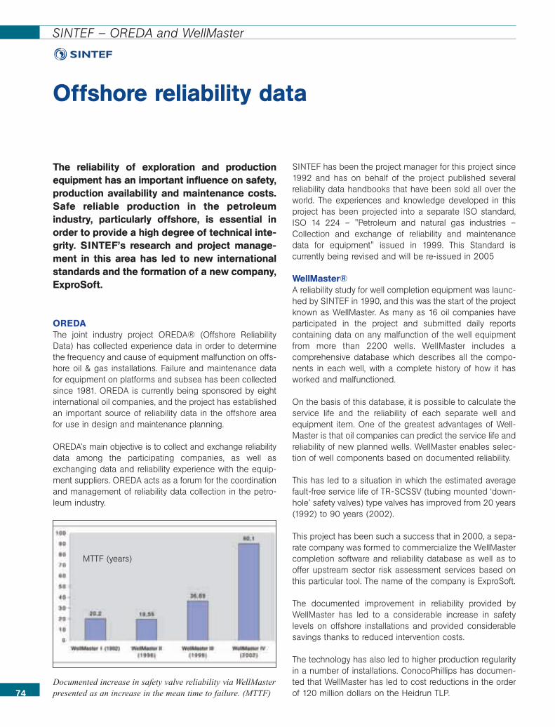
The reliability of exploration and productionequipment has an important influence on safety,production availability and maintenance costs.Safe reliable production in the petroleumindustry, particularly offshore, is essential inorder to provide a high degree of technical inte-grity. SINTEF’s research and project manage-ment in this area has led to new internationalstandards and the formation of a new company,ExproSoft.
OREDAThe joint industry project OREDA® (Offshore ReliabilityData) has collected experience data in order to determinethe frequency and cause of equipment malfunction on offs-hore oil & gas installations. Failure and maintenance datafor equipment on platforms and subsea has been collectedsince 1981. OREDA is currently being sponsored by eightinternational oil companies, and the project has establishedan important source of reliability data in the offshore areafor use in design and maintenance planning.
OREDA’s main objective is to collect and exchange reliabilitydata among the participating companies, as well asexchanging data and reliability experience with the equip-ment suppliers. OREDA acts as a forum for the coordinationand management of reliability data collection in the petro-leum industry.
SINTEF has been the project manager for this project since1992 and has on behalf of the project published severalreliability data handbooks that have been sold all over theworld. The experiences and knowledge developed in thisproject has been projected into a separate ISO standard,ISO 14 224 – "Petroleum and natural gas industries –Collection and exchange of reliability and maintenancedata for equipment" issued in 1999. This Standard iscurrently being revised and will be re-issued in 2005
WellMaster®A reliability study for well completion equipment was launc-hed by SINTEF in 1990, and this was the start of the projectknown as WellMaster. As many as 16 oil companies haveparticipated in the project and submitted daily reportscontaining data on any malfunction of the well equipmentfrom more than 2200 wells. WellMaster includes acomprehensive database which describes all the compo-nents in each well, with a complete history of how it hasworked and malfunctioned.
On the basis of this database, it is possible to calculate theservice life and the reliability of each separate well andequipment item. One of the greatest advantages of Well-Master is that oil companies can predict the service life andreliability of new planned wells. WellMaster enables selec-tion of well components based on documented reliability.
This has led to a situation in which the estimated averagefault-free service life of TR-SCSSV (tubing mounted ‘down-hole’ safety valves) type valves has improved from 20 years(1992) to 90 years (2002).
This project has been such a success that in 2000, a sepa-rate company was formed to commercialize the WellMastercompletion software and reliability database as well as tooffer upstream sector risk assessment services based onthis particular tool. The name of the company is ExproSoft.
The documented improvement in reliability provided byWellMaster has led to a considerable increase in safetylevels on offshore installations and provided considerablesavings thanks to reduced intervention costs.
The technology has also led to higher production regularityin a number of installations. ConocoPhillips has documen-ted that WellMaster has led to cost reductions in the orderof 120 million dollars on the Heidrun TLP.
Offshore reliability data
74
SINTEF – OREDA and WellMaster
Documented increase in safety valve reliability via WellMasterpresented as an increase in the mean time to failure. (MTTF)
MTTF (years)
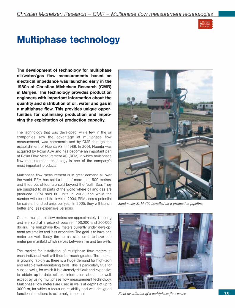
The development of technology for multiphaseoil/water/gas flow measurements based onelectrical impedance was launched early in the1980s at Christian Michelsen Research (CMR)in Bergen. The technology provides productionengineers with important information about thequantity and distribution of oil, water and gas ina multiphase flow. This provides unique oppor-tunities for optimising production and impro-ving the exploitation of production capacity.
The technology that was developed, while few in the oilcompanies saw the advantage of multiphase flowmeasurement, was commercialised by CMR through theestablishment of Fluenta AS in 1986. In 2001, Fluenta wasacquired by Roxar ASA and has become an important partof Roxar Flow Measurement AS (RFM) in which multiphaseflow measurement technology is one of the company’smost important products.
Multiphase flow measurement is in great demand all overthe world. RFM has sold a total of more than 500 metres,and three out of four are sold beyond the North Sea. Theyare supplied to all parts of the world where oil and gas areproduced. RFM sold 60 units in 2003, and while thenumber will exceed this level in 2004, RFM sees a potentialfor several hundred units per year. In 2005, they will launchbetter and less expensive versions.
Current multiphase flow meters are approximately 1 m longand are sold at a price of between 150,000 and 200,000dollars. The multiphase flow meters currently under develop-ment are smaller and less expensive. The goal is to have onemeter per well. Today, the normal situation is to have onemeter per manifold which serves between five and ten wells.
The market for installation of multiphase flow meters ateach individual well will thus be much greater. The marketis growing rapidly as there is a huge demand for high-techand reliable well-monitoring tools. This is particularly true forsubsea wells, for which it is extremely difficult and expensiveto obtain up-to-date reliable information about the well,except by using multiphase flow measurement technology.Multiphase flow meters are used in wells at depths of up to3000 m, for which a focus on reliability and well-designedfunctional solutions is extremely important.
Multiphase technology
75
Christian Michelsen Research – CMR – Multiphase flow measurement technologies
Field installation of a multiphase flow meter.
Sand meter SAM 400 installed on a production pipeline.

ABB slug control technology has not only contri-buted to increased oil production. Wherever ithas been implemented, in Norway and else-where in the world, it has limited slugging whilealso reducing flare burning and reducing oilspills to the sea.
For many years, ABB has developed and carried out researchon advanced control and optimization systems for the up-stream oil and gas industry. Many years of research work influid mechanics and cybernetics at the ABB ResearchCentre at Billingstad in Oslo has resulted in two solutions:Active Well Control and Active Flowline Control, whichstabilize slugging wells and pipelines respectively. Bothsolutions are categorized under the common concept of
Slug Control Solutions. Slugging wells and pipelines arethose that produce irregularly, almost like waves that breakon a beach. Waves that are too big put great stress on theprocess system on the platforms, while small waves do notfully exploit the potential of the process system. It is muchmore economical to produce at a constant rate, while thereservoir will not be subjected to great pressure fluctuations.Both slug control solutions use available pressure andtemperature from the well and the pipeline as inputs to themodel, which is used to calculate the choke aperture whichwill prevent the well or pipeline from slugging. The chokeaperture is regulated continuously so that the pressure inthe well is kept relatively constant, without fluctuations.When the pressure in the well or the pipeline fluctuates, itwill be appear that large fluid slugs are entering theprocess system, just as in the wave analogy above. A
tremendous slug may force theoperator to choke the well, i.e. toclose the valve and thus produceless. A slug control solution may helpto reduce pressure fluctuations, asshown in the illustration. Both slugcontrol solutions have been imple-mented by several major internationaloil companies, also here in the NorthSea. They have proven to be veryefficient in reducing slugging whilehelping to reduce flare burning andoil spills into the sea and to improveexploitation of the processingsystem. Another important effect isincreased oil production.
Slug control
76
ABB – Increased oil production
Active Well Control. Blue arrows: Inputto the model. Red arrows: Output tothe well.

Vetco Aibel AS has developed VIEC, a techno-logy that has increased the production on TrollC and which is now marketed to internationalcompanies. The project demonstrates thattechnology development in Norway is valuableboth for the supply industry and for the operators.
Vetco Aibel AS, previously ABB Offshore Systems AS, is akeystone company that supplies technology to the interna-tional oil and gas industry. Technology development is thecentral element in both the national and the internationalefforts of the company. VIEC is an innovation which hasbeen a great success for the company.
Since 2001, Vetco Aibel has been working on the develop-ment of an electrostatic coalescer that was designed to bemounted directly in the separator tank. The coalescer wascalled VIEC (Vessel Internal Electrostatic Coalescer). Theidea behind this equipment was to move the use of electro-static forces right into the high-pressure separator in orderto increase production capacity, reduce separation time,degrade layers of emulsion and reduce the use of chemi-cals and water in the oil at the separation stage.
Troll C Norsk Hydro became interested in the technology on thebackground of emulsion problems on the Troll C installati-on and in collaboration with the DEMO 2000 programme,a project started in January 2003 aimed at completing thedevelopment work and installing VIEC on Troll C in thesummer of 2003.
In July 2003, VIEC was installed on Troll C and right awaythere was a marked improvement in the separation pro-cess. It has been in operation ever since and the experiencehas confirmed that Troll C has had a 5 – 10 % increase inpetroleum production, a marked reduction of emulsion-prevention chemicals (80%) which has resulted in reducedoperating costs in the neighbourhood of 800 thousanddollars a year. Thus the cost of a VIEC in the Troll C casehas been saved on the basis of reduced chemicalconsumption alone.
Chinese watersThese tests have given Vetco Aibel a product of great inter-national interest. The next VIEC was sold to BluewaterFPSO Munin for use in Chinese waters. Munin started
working in October 2004. This shows that technology deve-lopment in Norway makes for a win-win situation for boththe supply industry and the operators, an essential conditionif the supply industry is to be able to maintain its internationalposition. 77
Vetco Aibel – Technology which increases production and improves the environment
VIEC has increased the production of Troll C
The Troll C platform.Photo: Terje S. Knudsen, Norsk Hydro.
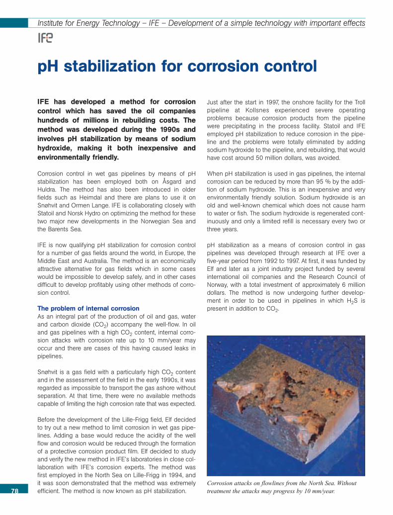
78
Institute for Energy Technology – IFE – Development of a simple technology with important effects
IFE has developed a method for corrosioncontrol which has saved the oil companieshundreds of millions in rebuilding costs. Themethod was developed during the 1990s andinvolves pH stabilization by means of sodiumhydroxide, making it both inexpensive andenvironmentally friendly.
Corrosion control in wet gas pipelines by means of pHstabilization has been employed both on Åsgard andHuldra. The method has also been introduced in olderfields such as Heimdal and there are plans to use it onSnøhvit and Ormen Lange. IFE is collaborating closely withStatoil and Norsk Hydro on optimizing the method for thesetwo major new developments in the Norwegian Sea andthe Barents Sea.
IFE is now qualifying pH stabilization for corrosion controlfor a number of gas fields around the world, in Europe, theMiddle East and Australia. The method is an economicallyattractive alternative for gas fields which in some caseswould be impossible to develop safely, and in other casesdifficult to develop profitably using other methods of corro-sion control.
The problem of internal corrosionAs an integral part of the production of oil and gas, waterand carbon dioxide (CO2) accompany the well-flow. In oiland gas pipelines with a high CO2 content, internal corro-sion attacks with corrosion rate up to 10 mm/year mayoccur and there are cases of this having caused leaks inpipelines.
Snøhvit is a gas field with a particularly high CO2 contentand in the assessment of the field in the early 1990s, it wasregarded as impossible to transport the gas ashore withoutseparation. At that time, there were no available methodscapable of limiting the high corrosion rate that was expected.
Before the development of the Lille-Frigg field, Elf decidedto try out a new method to limit corrosion in wet gas pipe-lines. Adding a base would reduce the acidity of the wellflow and corrosion would be reduced through the formationof a protective corrosion product film. Elf decided to studyand verify the new method in IFE’s laboratories in close col-laboration with IFE’s corrosion experts. The method wasfirst employed in the North Sea on Lille-Frigg in 1994, andit was soon demonstrated that the method was extremelyefficient. The method is now known as pH stabilization.
Just after the start in 1997, the onshore facility for the Trollpipeline at Kollsnes experienced severe operatingproblems because corrosion products from the pipelinewere precipitating in the process facility. Statoil and IFEemployed pH stabilization to reduce corrosion in the pipe-line and the problems were totally eliminated by addingsodium hydroxide to the pipeline, and rebuilding, that wouldhave cost around 50 million dollars, was avoided.
When pH stabilization is used in gas pipelines, the internalcorrosion can be reduced by more than 95 % by the addi-tion of sodium hydroxide. This is an inexpensive and veryenvironmentally friendly solution. Sodium hydroxide is anold and well-known chemical which does not cause harmto water or fish. The sodium hydroxide is regenerated cont-inuously and only a limited refill is necessary every two orthree years.
pH stabilization as a means of corrosion control in gaspipelines was developed through research at IFE over afive-year period from 1992 to 1997. At first, it was funded byElf and later as a joint industry project funded by severalinternational oil companies and the Research Council ofNorway, with a total investment of approximately 6 milliondollars. The method is now undergoing further develop-ment in order to be used in pipelines in which H2S ispresent in addition to CO2.
pH stabilization for corrosion control
Corrosion attacks on flowlines from the North Sea. Withouttreatment the attacks may progress by 10 mm/year.
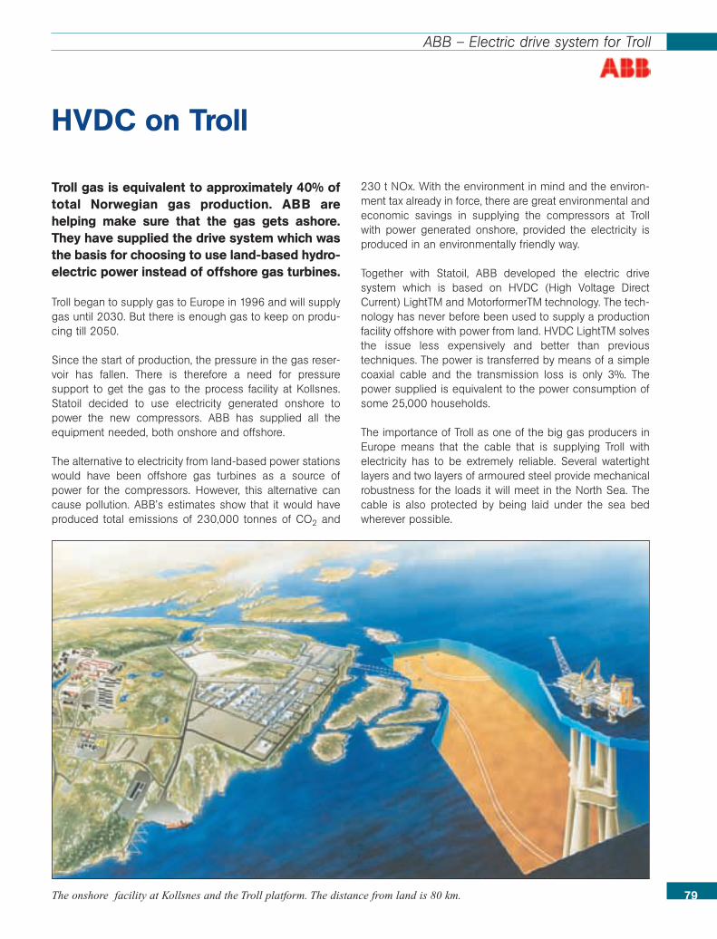
79
ABB – Electric drive system for Troll
HVDC on Troll
The onshore facility at Kollsnes and the Troll platform. The distance from land is 80 km.
Troll gas is equivalent to approximately 40% oftotal Norwegian gas production. ABB arehelping make sure that the gas gets ashore.They have supplied the drive system which wasthe basis for choosing to use land-based hydro-electric power instead of offshore gas turbines.
Troll began to supply gas to Europe in 1996 and will supplygas until 2030. But there is enough gas to keep on produ-cing till 2050.
Since the start of production, the pressure in the gas reser-voir has fallen. There is therefore a need for pressuresupport to get the gas to the process facility at Kollsnes.Statoil decided to use electricity generated onshore topower the new compressors. ABB has supplied all theequipment needed, both onshore and offshore.
The alternative to electricity from land-based power stationswould have been offshore gas turbines as a source ofpower for the compressors. However, this alternative cancause pollution. ABB’s estimates show that it would haveproduced total emissions of 230,000 tonnes of CO2 and
230 t NOx. With the environment in mind and the environ-ment tax already in force, there are great environmental andeconomic savings in supplying the compressors at Trollwith power generated onshore, provided the electricity isproduced in an environmentally friendly way.
Together with Statoil, ABB developed the electric drivesystem which is based on HVDC (High Voltage DirectCurrent) LightTM and MotorformerTM technology. The tech-nology has never before been used to supply a productionfacility offshore with power from land. HVDC LightTM solvesthe issue less expensively and better than previoustechniques. The power is transferred by means of a simplecoaxial cable and the transmission loss is only 3%. Thepower supplied is equivalent to the power consumption ofsome 25,000 households.
The importance of Troll as one of the big gas producers inEurope means that the cable that is supplying Troll withelectricity has to be extremely reliable. Several watertightlayers and two layers of armoured steel provide mechanicalrobustness for the loads it will meet in the North Sea. Thecable is also protected by being laid under the sea bedwherever possible.
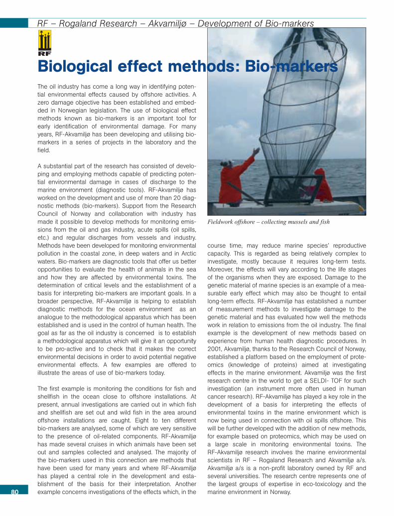
The oil industry has come a long way in identifying poten-tial environmental effects caused by offshore activities. Azero damage objective has been established and embed-ded in Norwegian legislation. The use of biological effectmethods known as bio-markers is an important tool forearly identification of environmental damage. For manyyears, RF-Akvamiljø has been developing and utilising bio-markers in a series of projects in the laboratory and thefield.
A substantial part of the research has consisted of develo-ping and employing methods capable of predicting poten-tial environmental damage in cases of discharge to themarine environment (diagnostic tools). RF-Akvamiljø hasworked on the development and use of more than 20 diag-nostic methods (bio-markers). Support from the ResearchCouncil of Norway and collaboration with industry hasmade it possible to develop methods for monitoring emis-sions from the oil and gas industry, acute spills (oil spills,etc.) and regular discharges from vessels and industry.Methods have been developed for monitoring environmentalpollution in the coastal zone, in deep waters and in Arcticwaters. Bio-markers are diagnostic tools that offer us betteropportunities to evaluate the health of animals in the seaand how they are affected by environmental toxins. Thedetermination of critical levels and the establishment of abasis for interpreting bio-markers are important goals. In abroader perspective, RF-Akvamiljø is helping to establishdiagnostic methods for the ocean environment as ananalogue to the methodological apparatus which has beenestablished and is used in the control of human health. Thegoal as far as the oil industry is concerned is to establisha methodological apparatus which will give it an opportunityto be pro-active and to check that it makes the correctenvironmental decisions in order to avoid potential negativeenvironmental effects. A few examples are offered toillustrate the areas of use of bio-markers today.
The first example is monitoring the conditions for fish andshellfish in the ocean close to offshore installations. Atpresent, annual investigations are carried out in which fishand shellfish are set out and wild fish in the area aroundoffshore installations are caught. Eight to ten different bio-markers are analysed, some of which are very sensitiveto the presence of oil-related components. RF-Akvamiljøhas made several cruises in which animals have been setout and samples collected and analysed. The majority ofthe bio-markers used in this connection are methods thathave been used for many years and where RF-Akvamiljøhas played a central role in the development and esta-blishment of the basis for their interpretation. Anotherexample concerns investigations of the effects which, in the
course time, may reduce marine species’ reproductivecapacity. This is regarded as being relatively complex toinvestigate, mostly because it requires long-term tests.Moreover, the effects will vary according to the life stagesof the organisms when they are exposed. Damage to thegenetic material of marine species is an example of a mea-surable early effect which may also be thought to entaillong-term effects. RF-Akvamiljø has established a numberof measurement methods to investigate damage to thegenetic material and has evaluated how well the methodswork in relation to emissions from the oil industry. The finalexample is the development of new methods based onexperience from human health diagnostic procedures. In2001, Akvamiljø, thanks to the Research Council of Norway,established a platform based on the employment of prote-omics (knowledge of proteins) aimed at investigatingeffects in the marine environment. Akvamiljø was the firstresearch centre in the world to get a SELDI- TOF for suchinvestigation (an instrument more often used in humancancer research). RF-Akvamiljø has played a key role in thedevelopment of a basis for interpreting the effects ofenvironmental toxins in the marine environment which isnow being used in connection with oil spills offshore. Thiswill be further developed with the addition of new methods,for example based on proteomics, which may be used ona large scale in monitoring environmental toxins. The RF-Akvamiljø research involves the marine environmentalscientists in RF – Rogaland Research and Akvamiljø a/s.Akvamiljø a/s is a non-profit laboratory owned by RF andseveral universities. The research centre represents one ofthe largest groups of expertise in eco-toxicology and themarine environment in Norway.80
Fieldwork offshore – collecting mussels and fish
Biological effect methods: Bio-markers
RF – Rogaland Research – Akvamiljø – Development of Bio-markers
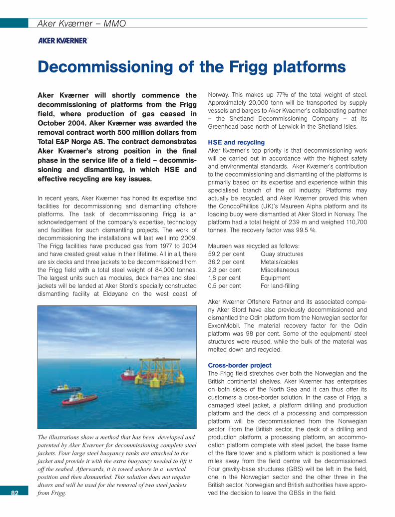
82
Aker Kværner – MMO
Aker Kværner will shortly commence thedecommissioning of platforms from the Friggfield, where production of gas ceased inOctober 2004. Aker Kværner was awarded theremoval contract worth 500 million dollars fromTotal E&P Norge AS. The contract demonstratesAker Kværner’s strong position in the finalphase in the service life of a field – decommis-sioning and dismantling, in which HSE andeffective recycling are key issues.
In recent years, Aker Kværner has honed its expertise andfacilities for decommissioning and dismantling offshoreplatforms. The task of decommissioning Frigg is anacknowledgement of the company’s expertise, technologyand facilities for such dismantling projects. The work ofdecommissioning the installations will last well into 2009.The Frigg facilities have produced gas from 1977 to 2004and have created great value in their lifetime. All in all, thereare six decks and three jackets to be decommissioned fromthe Frigg field with a total steel weight of 84,000 tonnes.The largest units such as modules, deck frames and steeljackets will be landed at Aker Stord’s specially constructeddismantling facility at Eldøyane on the west coast of
Norway. This makes up 77% of the total weight of steel.Approximately 20,000 tonn will be transported by supplyvessels and barges to Aker Kvaerner’s collaborating partner – the Shetland Decommissioning Company – at itsGreenhead base north of Lerwick in the Shetland Isles.
HSE and recyclingAker Kværner’s top priority is that decommissioning workwill be carried out in accordance with the highest safetyand environmental standards. Aker Kværner’s contributionto the decommissioning and dismantling of the platforms isprimarily based on its expertise and experience within thisspecialised branch of the oil industry. Platforms mayactually be recycled, and Aker Kværner proved this whenthe ConocoPhillips (UK)’s Maureen Alpha platform and itsloading buoy were dismantled at Aker Stord in Norway. Theplatform had a total height of 239 m and weighed 110,700tonnes. The recovery factor was 99.5 %.
Maureen was recycled as follows: 59.2 per cent Quay structures36.2 per cent Metals/cables2,3 per cent Miscellaneous1,8 per cent Equipment0.5 per cent For land-filling
Aker Kværner Offshore Partner and its associated compa-ny Aker Stord have also previously decommissioned anddismantled the Odin platform from the Norwegian sector forExxonMobil. The material recovery factor for the Odinplatform was 98 per cent. Some of the equipment/ steelstructures were reused, while the bulk of the material wasmelted down and recycled.
Cross-border projectThe Frigg field stretches over both the Norwegian and theBritish continental shelves. Aker Kværner has enterpriseson both sides of the North Sea and it can thus offer itscustomers a cross-border solution. In the case of Frigg, adamaged steel jacket, a platform drilling and productionplatform and the deck of a processing and compressionplatform will be decommissioned from the Norwegiansector. From the British sector, the deck of a drilling andproduction platform, a processing platform, an accommo-dation platform complete with steel jacket, the base frameof the flare tower and a platform which is positioned a fewmiles away from the field centre will be decomissioned.Four gravity-base structures (GBS) will be left in the field,one in the Norwegian sector and the other three in theBritish sector. Norwegian and British authorities have appro-ved the decision to leave the GBSs in the field.
Decommissioning of the Frigg platforms
The illustrations show a method that has been developed andpatented by Aker Kværner for decommissioning complete steeljackets. Four large steel buoyancy tanks are attached to thejacket and provide it with the extra buoyancy needed to lift itoff the seabed. Afterwards, it is towed ashore in a verticalposition and then dismantled. This solution does not requiredivers and will be used for the removal of two steel jacketsfrom Frigg.
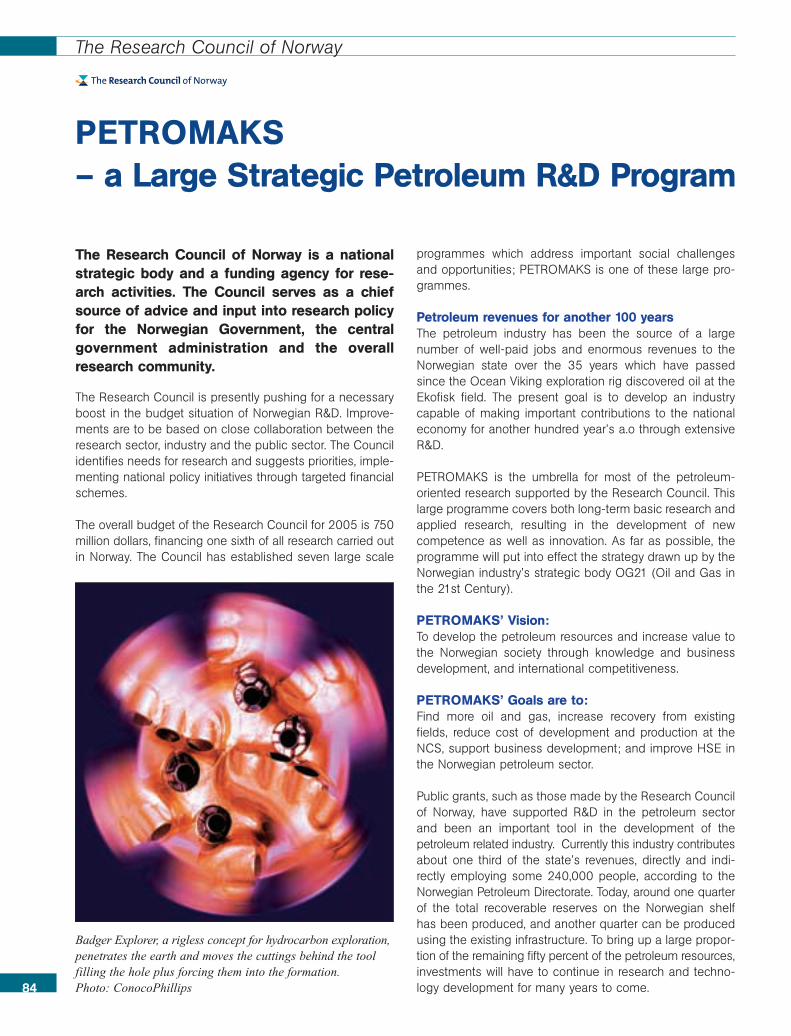
84
The Research Council of Norway
The Research Council of Norway is a nationalstrategic body and a funding agency for rese-arch activities. The Council serves as a chiefsource of advice and input into research policyfor the Norwegian Government, the centralgovernment administration and the overallresearch community.
The Research Council is presently pushing for a necessaryboost in the budget situation of Norwegian R&D. Improve-ments are to be based on close collaboration between theresearch sector, industry and the public sector. The Councilidentifies needs for research and suggests priorities, imple-menting national policy initiatives through targeted financialschemes.
The overall budget of the Research Council for 2005 is 750million dollars, financing one sixth of all research carried outin Norway. The Council has established seven large scale
programmes which address important social challengesand opportunities; PETROMAKS is one of these large pro-grammes.
Petroleum revenues for another 100 yearsThe petroleum industry has been the source of a largenumber of well-paid jobs and enormous revenues to theNorwegian state over the 35 years which have passedsince the Ocean Viking exploration rig discovered oil at theEkofisk field. The present goal is to develop an industrycapable of making important contributions to the nationaleconomy for another hundred year’s a.o through extensiveR&D.
PETROMAKS is the umbrella for most of the petroleum-oriented research supported by the Research Council. Thislarge programme covers both long-term basic research andapplied research, resulting in the development of newcompetence as well as innovation. As far as possible, theprogramme will put into effect the strategy drawn up by theNorwegian industry’s strategic body OG21 (Oil and Gas inthe 21st Century).
PETROMAKS’ Vision:To develop the petroleum resources and increase value tothe Norwegian society through knowledge and businessdevelopment, and international competitiveness.
PETROMAKS’ Goals are to:Find more oil and gas, increase recovery from existingfields, reduce cost of development and production at theNCS, support business development; and improve HSE inthe Norwegian petroleum sector.
Public grants, such as those made by the Research Councilof Norway, have supported R&D in the petroleum sectorand been an important tool in the development of thepetroleum related industry. Currently this industry contributesabout one third of the state’s revenues, directly and indi-rectly employing some 240,000 people, according to theNorwegian Petroleum Directorate. Today, around one quarterof the total recoverable reserves on the Norwegian shelfhas been produced, and another quarter can be producedusing the existing infrastructure. To bring up a large propor-tion of the remaining fifty percent of the petroleum resources,investments will have to continue in research and techno-logy development for many years to come.
PETROMAKS – a Large Strategic Petroleum R&D Program
Badger Explorer, a rigless concept for hydrocarbon exploration,penetrates the earth and moves the cuttings behind the toolfilling the hole plus forcing them into the formation.Photo: ConocoPhillips
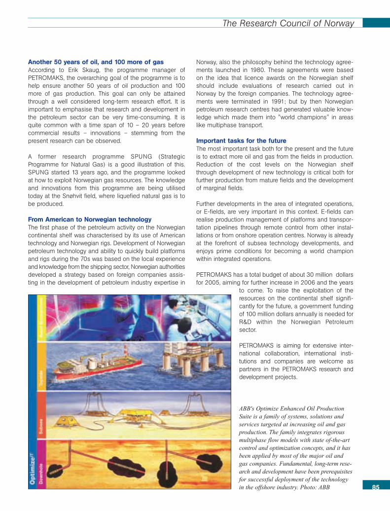
85
The Research Council of Norway
Another 50 years of oil, and 100 more of gasAccording to Erik Skaug, the programme manager ofPETROMAKS, the overarching goal of the programme is tohelp ensure another 50 years of oil production and 100more of gas production. This goal can only be attainedthrough a well considered long-term research effort. It isimportant to emphasise that research and development inthe petroleum sector can be very time-consuming. It isquite common with a time span of 10 – 20 years beforecommercial results – innovations – stemming from thepresent research can be observed.
A former research programme SPUNG (StrategicProgramme for Natural Gas) is a good illustration of this.SPUNG started 13 years ago, and the programme lookedat how to exploit Norwegian gas resources. The knowledgeand innovations from this programme are being utilisedtoday at the Snøhvit field, where liquefied natural gas is tobe produced.
From American to Norwegian technologyThe first phase of the petroleum activity on the Norwegiancontinental shelf was characterised by its use of Americantechnology and Norwegian rigs. Development of Norwegianpetroleum technology and ability to quickly build platformsand rigs during the 70s was based on the local experienceand knowledge from the shipping sector, Norwegian authoritiesdeveloped a strategy based on foreign companies assis-ting in the development of petroleum industry expertise in
Norway, also the philosophy behind the technology agree-ments launched in 1980. These agreements were basedon the idea that licence awards on the Norwegian shelfshould include evaluations of research carried out inNorway by the foreign companies. The technology agree-ments were terminated in 1991; but by then Norwegianpetroleum research centres had generated valuable know-ledge which made them into "world champions" in areaslike multiphase transport.
Important tasks for the futureThe most important task both for the present and the futureis to extract more oil and gas from the fields in production.Reduction of the cost levels on the Norwegian shelfthrough development of new technology is critical both forfurther production from mature fields and the developmentof marginal fields.
Further developments in the area of integrated operations,or E-fields, are very important in this context. E-fields canrealise production management of platforms and transpor-tation pipelines through remote control from other instal-lations or from onshore operation centres. Norway is alreadyat the forefront of subsea technology developments, andenjoys prime conditions for becoming a world championwithin integrated operations.
PETROMAKS has a total budget of about 30 million dollarsfor 2005, aiming for further increase in 2006 and the years
to come. To raise the exploitation of theresources on the continental shelf signifi-cantly for the future, a government fundingof 100 million dollars annually is needed forR&D within the Norwegian Petroleumsector.
PETROMAKS is aiming for extensive inter-national collaboration, international insti-tutions and companies are welcome aspartners in the PETROMAKS research anddevelopment projects.
ABB's Optimize Enhanced Oil ProductionSuite is a family of systems, solutions andservices targeted at increasing oil and gasproduction. The family integrates rigorousmultiphase flow models with state of-the-artcontrol and optimization concepts, and it hasbeen applied by most of the major oil andgas companies. Fundamental, long-term rese-arch and development have been prerequisitesfor successful deployment of the technologyin the offshore industry. Photo: ABB
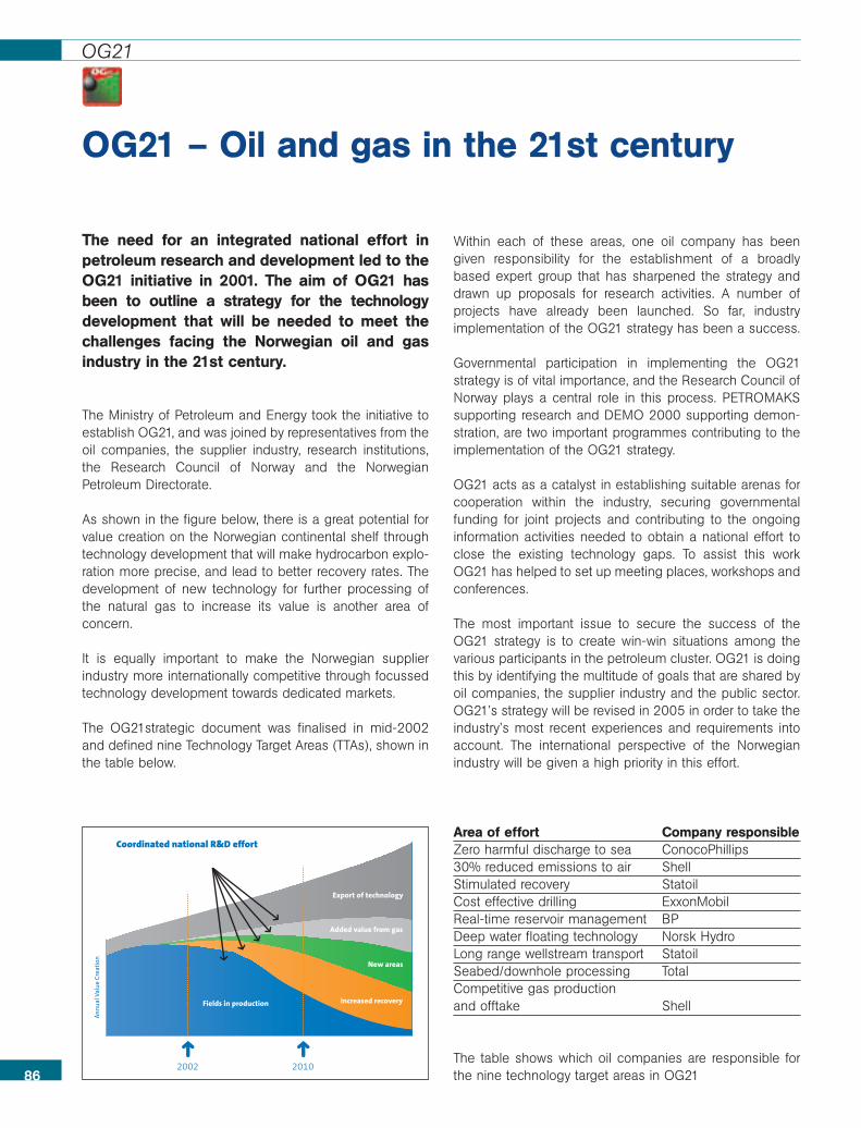
86
OG21
The need for an integrated national effort inpetroleum research and development led to theOG21 initiative in 2001. The aim of OG21 hasbeen to outline a strategy for the technologydevelopment that will be needed to meet thechallenges facing the Norwegian oil and gasindustry in the 21st century.
The Ministry of Petroleum and Energy took the initiative toestablish OG21, and was joined by representatives from theoil companies, the supplier industry, research institutions,the Research Council of Norway and the NorwegianPetroleum Directorate.
As shown in the figure below, there is a great potential forvalue creation on the Norwegian continental shelf throughtechnology development that will make hydrocarbon explo-ration more precise, and lead to better recovery rates. Thedevelopment of new technology for further processing ofthe natural gas to increase its value is another area ofconcern.
It is equally important to make the Norwegian supplierindustry more internationally competitive through focussedtechnology development towards dedicated markets.
The OG21strategic document was finalised in mid-2002and defined nine Technology Target Areas (TTAs), shown inthe table below.
Within each of these areas, one oil company has beengiven responsibility for the establishment of a broadlybased expert group that has sharpened the strategy anddrawn up proposals for research activities. A number ofprojects have already been launched. So far, industryimplementation of the OG21 strategy has been a success.
Governmental participation in implementing the OG21strategy is of vital importance, and the Research Council ofNorway plays a central role in this process. PETROMAKSsupporting research and DEMO 2000 supporting demon-stration, are two important programmes contributing to theimplementation of the OG21 strategy.
OG21 acts as a catalyst in establishing suitable arenas forcooperation within the industry, securing governmentalfunding for joint projects and contributing to the ongoinginformation activities needed to obtain a national effort toclose the existing technology gaps. To assist this workOG21 has helped to set up meeting places, workshops andconferences.
The most important issue to secure the success of theOG21 strategy is to create win-win situations among thevarious participants in the petroleum cluster. OG21 is doingthis by identifying the multitude of goals that are shared byoil companies, the supplier industry and the public sector.OG21’s strategy will be revised in 2005 in order to take theindustry’s most recent experiences and requirements intoaccount. The international perspective of the Norwegianindustry will be given a high priority in this effort.
OG21 – Oil and gas in the 21st century
Area of effort Company responsibleZero harmful discharge to sea ConocoPhillips30% reduced emissions to air ShellStimulated recovery StatoilCost effective drilling ExxonMobilReal-time reservoir management BPDeep water floating technology Norsk HydroLong range wellstream transport StatoilSeabed/downhole processing TotalCompetitive gas production and offtake Shell
The table shows which oil companies are responsible forthe nine technology target areas in OG21
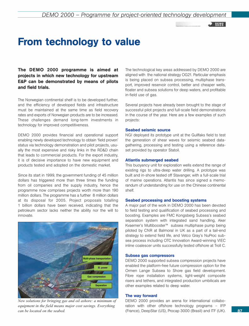
87
DEMO 2000 – Programme for project-oriented technology development
The DEMO 2000 programme is aimed atprojects in which new technology for upstreamE&P can be demonstrated by means of pilotsand field trials.
The Norwegian continental shelf is to be developed further,and the efficiency of developed fields and infrastructuremust be maintained at the same time as field recoveryrates and exports of Norwegian products are to be increased.These challenges demand long-term investments intechnology for improved competitiveness.
DEMO 2000 provides financial and operational supportenabling newly developed technology to obtain ‘field proven’status via technology demonstration and pilot projects, usu-ally the most expensive and risky links in the RD&D chainthat leads to commercial products. For the export industry,it is of decisive importance to have new equipment andproducts tested and adopted on the domestic market.
Since its start in 1999, the government funding of 45 milliondollars has triggered more than three times the fundingfrom oil companies and the supply industry, hence theprogramme now comprises projects worth more than 190million dollars. The programme has a further 8 million dollarsat its disposal for 2005. Project proposals totalling 1 billion dollars have been received, indicating that thepetroleum sector lacks neither the ability nor the will toinnovate.
The technological key areas addressed by DEMO 2000 arealigned with the national strategy OG21. Particular emphasisis being placed on subsea processing, multiphase trans-port, improved reservoir control, better and cheaper wells,floater and subsea solutions for deep waters, and profitablein-field use of gas.
Several projects have already been brought to the stage ofsuccessful pilot projects and full-scale field demonstrationsin the course of the year. Here are a few examples of suchprojects:
Seabed seismic source NGI deployed its prototype unit at the Gullfaks field to testthe generation of shear waves for seismic seabed data-gathering, processing and testing using a reference data-set provided by operator Statoil.
Atlantis submerged seabedThis buoyancy unit for exploration wells extend the range ofexisting rigs to ultra-deep water drilling. A prototype wasbuilt and in-shore tested off Stavanger, with a full-scale trialof marine operations. Atlantis has since signed a memo-randum of understanding for use on the Chinese continentalshelf.
Seabed processing and boosting systemsA major part of the work in DEMO 2000 has been devotedto field testing and qualification of seabed processing andboosting. Examples are FMC Kongsberg Subsea’s seabedseparation system with integrated sand handling, AkerKvaerner’s Multibooster™ subsea multiphase pump beingpiloted by CNR at Balmoral in UK as a part of a tail-endstrategy to extend field life, and Vetco Gray’s NuProc sub-sea process including OTC Innovation Award-winning VIECinline coalescer units successfully tested offshore at Troll C.
Subsea gas compressorsDEMO 2000 supported subsea compression projects haveenabled the platform-free future compression option for theOrmen Lange Subsea to Shore gas field development.Fibre rope installation systems, light-weight compositerisers and tethers, and integrated production umbilicals areother examples related to deep water.
The way forwardDEMO 2000 provides an arena for international collabo-ration with other offshore technology programs – IFP(France), DeepStar (US), Procap 3000 (Brasil) and ITF (UK).
From technology to value
New solutions for bringing gas and oil ashore: a minimum ofequipment in the field means major cost savings. Everythingcan be located on the seabed.
Separation
Multi-phase transportation
El. power
Gas compression

89
Acknowledgements
Companies and institutions that have contributed financially and withtext and illustrations to make the production of this book possible
ABB ASBergerveien 12N-1375 BillingstadPhone: 0047 03500Fax: 0047 66 84 35 49Web: www.abb.no
Aker Kværner ASAP.O. Box 1691325 LysakerNorwayPhone: 0047 67 51 30 00Fax: 0047 67 51 30 10Web: www.akerkvaerner.com
Baker Oil ToolsP.O. Box 2224098 TanangerNorwayPhone: 0047 51 71 70 00Fax: 0047 51 71 70 10Web: bakerhughes.com
Christian Michelsen Research ASP.O. Box 6031, Postterminalen5892 BergenNorwayPhone: 0047 55 57 40 40Fax: 0047 55 57 40 41Web: www.cmr.no
ConocoPhillips NorgeP.O. Box 2204098 TanangerNorwayPhone: 0047 52 02 00 00Fax: 0047 52 02 66 00Web: www.conocophillips.no
DEMO 2000Boks 2700, St. Hanshaugen0131 OSLONorwayPhone: 0047 22 03 74 40Fax: 0047 22 03 74 61Web: www.demo2000.no
DNV1322 HøvikNorwayPhone: 0047 67 57 99 00Fax: 0047 67 57 99 11Web: www.dnv.no
FMC Technologies Subsea SystemsP.O. Box 10123061 KongsbergNorwayPhone: 0047 32 28 67 00Fax: 0047 32 28 67 50Web: www.fmctechnologies.com
Hydro Oil and EnergyN-0240 OSLO Phone: 0047 22 53 81 00 Fax: 0047 22 53 27 25 Web: www.hydro.com
Institute for Energy TechnologyP.O. Box 402027 KjellerNorwayPhone: 0047 63 80 60 00Fax: 0047 63 81 63 56
Institute for Energy TechnologyP.O. Box 1731751 HaldenNorwayPhone: 0047 69 21 22 00Fax: 0047 69 21 22 01Web: www.ife.no
INTSOKP.O. Box 631, SkøyenN-0214 OsloPhone: 0047 22 06 14 80Fax: 0047 22 06 14 90Web: www.intsok.com
MARINTEK ASP.O. Box 4125 – Valentinlyst7450 TrondheimNorwayPhone: 0047 73 59 55 00Fax 0047 73 59 57 76Web: www.marintek.com
Kongsberg Maritime P.O.Box 483 N-3601 KONGSBERG Phone: 0047 32 28 50 00 Fax: 0047 32 73 59 87 Web: www.km.kongsberg.com
NGIP.O. Box 3930 Ullevål Stadion0806 OsloNorwayPhone: 0047 22 02 30 00Fax: 0047 22 23 04 48Web: www.ngi.no
Offshore Media Group ASP.O. Box 1335 Vika0112 OSLONorwayPhone: 0047 55 90 45 70Fax: 0047 55 90 45 79Web: www.offshore.nowww.oilport.net
OG21 c/o The Research Council of Norway Boks 2700, St. Hanshaugen N-0131 OSLO Phone: 0047 22 03.74 94 Fax: 0047 22 03 74 61 Web: www.og21.org
The Research Council of Norway P.O. Box 2700 St. Hanshaugen N-0130 Oslo Phone: 0047 22 03 70 00 Fax: 0047 22 03 70 01 Web: www.forskningsradet.no
Remora Technology ASVikaveien 294817 HisNorwayPhone: 0047 37 06 03 50Fax: 0047 37 06 03 51Web: www.remora.no
RF - Rogaland ResearchP.O. Box 80464068 StavangerNorwayPhone: 0047 51 87 50 00Fax: 0047 51 87 52 00Web: www.rf.no
Schlumberger Oilfield ServicesP.O. Box 80134068 StavangerNorwayPhone: 0047 51 94 60 00Fax: 0047 51 94 60 01Web: www.slb.com
SINTEFStrindveien 47465 TrondheimNorwayPhone: 0047 73 59 30 00Fax: 0047 73 59 33 50Web: www.sintef.com
SINTEF Petroleum ResearchS. P. Andersens vei 15b7465 TrondheimNorwayPhone: 0047 73 59 11 00Fax: 0047 73 59 11 02Web: www.sintef.com/petroleum
SINTEF Energy ResearchSem Sælands vei 117465 TrondheimNorwayPhone: 0047 73 59 72 00Fax: 0047 73 59 72 50Web: www.sintef.com/energy
StatoilForusbeen 504035 StavangerNorwayPhone: 0047 51 99 00 00Fax: 0047 51 99 00 50Web: www.statoil.com
VetcoP.O. Box 811361 BillingstadNorwayPhone: 0047 66 84 3060Fax: 0047 66 84 4099Web: www.vetcogray.com