northgate excavations · excavation was to relocate the position of the northgate of the roman...
TRANSCRIPT
21
NORTHGATE EXCAVATIONS
S Bryant M Morris V Tanner and J Walker
INTRODUCTION
Site Location , ,
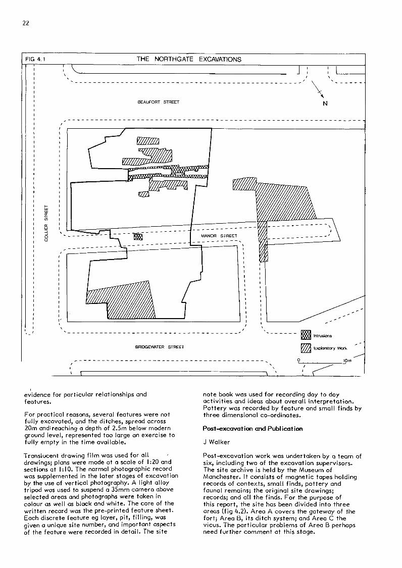
The site was located in the'Castlefield districtof Manchester and was bounded by BridgewaterStreet to the north, Collier Street to the east,Beaufort Street to the south and Wellington Millsto the west (fig 4.1). The site had remainedlargely vacant since the 1960s after thedemolition of 19th century slum dwellings.
S*'Excavation Organisation
During May 1979, excavations directed by ProfessorG D B Jones commenced. The initial aim of theexcavation was to relocate the position of theNorthgate of the Roman fort, previously observedby Fetch (1951).
Excavations continued sporadically throughout I960and from the autumn of that year the work wasdirected by the Greater Manchester ArchaeologicalUnit. The twenty strong team, sponsored by theManpower Services Commission, was led by M Morris.P Reynolds and S Bryant also helped to supervisethe excavations. The programme of work carried outduring the following months was designed tofurther elucidate the chronology of the fort, itsditches and associated civilian settlement(vicus). The excavated area was expanded into 1981to the north in the vicus (Area C) and later tothe south after the demolition of a building inthat corner of the site gave access for the firsttime to the east pier of the gateway (Area A).
Modem Deposits
As had been expected from the results of previouswork in the vicinity (Jones & Grealey 1974, 49),the archaeological deposits were found not farbelow the modern surface, at a depth of between0.25m and 0.5m. In Area A, (fig 4.2) levellingdown associated with the 19th century buildingactivity had substantially damaged the remains ofthe fort, gateway and rampart. In addition two
drain trenches lay across the area, cuttingthrough the archaeological deposits and into thenatural gravel and sand-subsoil. Together with theearlier archaeological trenches and sondages(Petch 1951; 1954; 1956) these had removed manystratigraphic relationships especially in thevicinity of the gateway. As a result of all thispost-Medieval damage, the turf rampart onlysurvived to a height of 0.9m, and no more than twofacing stones from the stone revetment survived insitu, although substantial foundations werepresent. Similarly only the foundations of thestone gateway were recovered and the remains ofthe earlier timber gateways were heavily damagedby both the insertion of the stone gateway andmodern activity.
In contrast, the defensive ditch complex andassociated features in front of the gateway (AreaB) were relatively undisturbed by modernactivitiy. The major factor affecting the recoveryof the ditch sequence was the destruction wroughtby subsequent recuts and alterations that tookplace in the Roman period.
The area to the north of the defences wassubstantially damaged by 19th century cellars.These intrusions limited the area of the vicus(civil settlement) available for excavation (AreaC). Here the archaeological deposits layimmediately below the modern surface, and theinterface between the Roman and Georgian levelssuggested that modern disturbance in this area hadnot been significant.
Excavation and Recording Techniques
The site was excavated in stratigraphic sequencein open areas, with baulks being left in relevantpositions for the removal of spoil. The modernoverburden, consisting mainly of car parkmetalling and demolition rubble was removed bymachining and the areas were cleaned bytrowelling. Where drain trenches and 1950sexcavations were encountered they were emptied andthe exposed sections examined and recorded. Inseveral instances these formed the only surviving
22
THE NORTHGATE EXCAVATIONS
evidence for particular relationships andfeatures.
For practical reasons, several features were notfully excavated, and the ditches, spread across20m and!reaching a depth of 2.5m below modernground level, represented too large an exercise tofully empty in the time available.
Translucent drawing film was used for alldrawings; plans were made at a scale of 1:20 andsections at 1:10. The normal photographic recordwas supplemented in the later stages of excavationby the use of vertical photography. A light alloytripod was used to suspend a 35mm camera aboveselected areas and photographs were taken incolour as well as black and white. The core of thewritten record was the pre-printed feature sheet.Each discrete feature eg layer, pit, filling, wasgiven a unique site number, and important aspectsof the feature were recorded in detail. The site
note book was used for recording day to dayactivities and ideas about overall interpretation.Pottery was recorded by feature and small finds bythree dimensional co-ordinates.
Post-excavation and Publication
J Walker
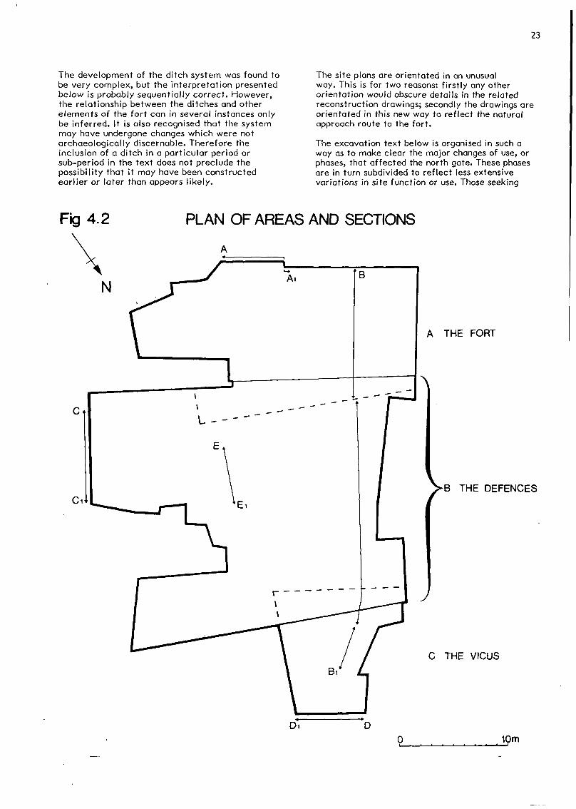
Post-excavation work was undertaken by a team ofsix, including two of the excavation supervisors.The site archive is held by the Museum ofManchester. It consists of magnetic tapes holdingrecords of contexts, small finds, pottery andfaunal remains; the original site drawings;records; and all the finds. For the purpose ofthis report, the site has been divided into threeareas (fig 4.2). Area A covers the gateway of thefort; Area B, its ditch system; and Area C thevicus. The particular problems of Area B perhapsneed further comment at this stage.
23
The development of the ditch system was found tobe very complex, but the interpretation presentedbelow is probably sequentially correct. However,the relationship between the ditches and otherelements of the fort can in several instances onlybe inferred. It is also recognised that the systemmay have undergone changes which were notarchaeologically discernable. Therefore theinclusion of a ditch in a particular period orsub-period in the text does not preclude thepossibility that it may have been constructedearlier or later than appears likely.
The site plans are orientated in an unusualway. This is for two reasons: firstly any otherorientation would obscure details in the relatedreconstruction drawings; secondly the drawings areorientated in this new way to reflect the naturalapproach route to the fort.
The excavation text below is organised in such away as to make clear the major changes of use, orphases, that affected the north gate. These phasesare in turn subdivided to reflect less extensivevariations in site function or use. Those seeking
Fig 4.2 PLAN OF AREAS AND SECTIONS
A THE FORT
B THE DEFENCES
C THE VICUS
D
0 10m

CO
1̂-O)
LL

25
a broad review of activities taking place on thesite should read the discussions only, as thedescriptions are provided to aid reinterpretation.
PHASE I AREA A (fig 4.3)
S Bryant
Description
The Northgate
The amount of disturbance caused to the Phase Iand 2 deposits by the insertion of the Phase 3stone gateway foundations, the previousarchaeological trenches (Petch 1951; 1954; 1956)and the services for the houses which stood on thesite, meant that the successive timber structuresof the Phase I and 2 Northgates were onlyrepresented by a fragmentary series of post holes.As an added difficulty there was little or noclear stratigraphic distinction between theoriginal Phase I post holes and their Phase 2replacements. For the sake of convenience, as wellas the fact that it is inherently more likely thatthe initial Phase I gateway was constructed on aregular grid, the more regularly spaced post holeshave been assigned to the Phase I gateway, andtheir replacements to the Phase 2 gateway.
The West Tower
This was represented by the bottom of four postsettings or holes which varied in depth between0.2m and 0.4m. The profile of all of the Phase Iand 2 Northgate post holes was, however, heavilytruncated by later disturbances, making itimpossible to determine the original dimensions ofthe holes. The reconstructed gateway plans on PlanA and Plan B are therefore based on the survivingpost hole dimensions, and the proposed additionalpost holes on an average of the surviving holes.The post holes contained a filling of grey sandysilt loam, which probably represented either therapid silting of the post holes after removal ofthe posts, or deliberate backfilling.
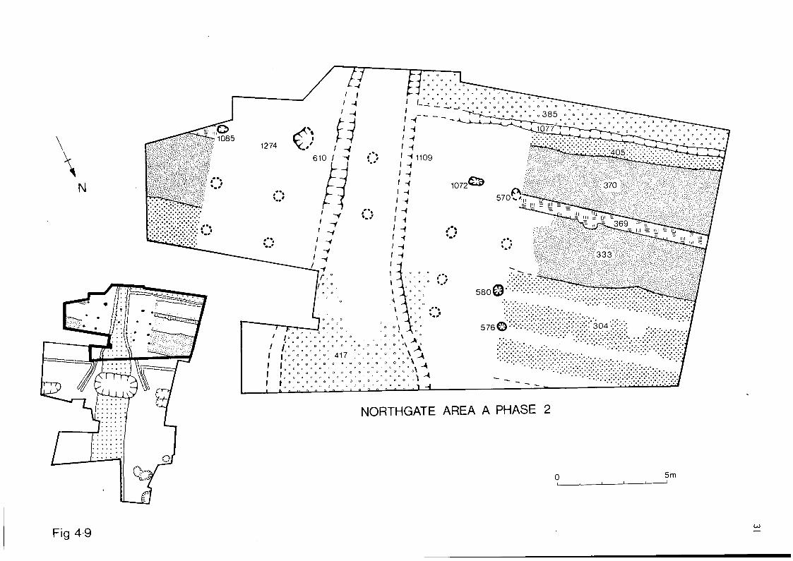
Post hole FI07I was situated at the back of thegateway, adjacent to the gateway passage, and inline with the rampart F369. Post holes F570, F580and F576 formed a north-south line 2.6m to thewest and adjacent to the east end of the rampart.The short distance of 1.6m between F576 and F580
suggests that the west tower may have been formedon a grid pattern of eight posts, and thisarrangement has been adopted in Plan A and Plan B.
Immediately to the rear of the west tower postholes (FI071 and F570) a number of small post andstake holes were observed, which formed arectangular structure, FI075, 2.8m by 3.2m.Several of these structural features also appearto have been replacements or additions to theoriginal structure.
A hearth consisting of a burnt pink clay layer0. Im thick, Fl 1 I I, which was probably used forcooking, was located within the internal area ofthe structure FI075. Also within it was a group ofstake holes, several of which formed a smallcircle adjacent to the hearth, and a buriedupright, almost complete, globular amphora FI737which contained the remains of small mammals,amphibians and fish, in its primary silt. All ofthe structural features associated with FI075 andFl I I I, behind the east tower, were cut intonatural sand and were filled with charcoal orburnt clay mixed with charcoal.
The East Tower
Only two post holes FI279 and FI085, belonging tothis tower survived from Phase I. Both lay in aline with the rear of the rampart turf stack,F369, and were of a similar depth to and containedthe same filling as the post holes of the westtower.
The Gateway Portal
No evidence was found for the portal having beenmetalled during Phase I, although the primary exitroad (F4I7) extended for approximately 1.5m intothe gateway. Within the portal were two drainageditches F6IO and Fl 109 (fig 4.4) which were filledwith clay and charcoal that were probably derivedfrom the demolition of the later Phase 2a fort;there was no evidence of primary silting. Theterminal ends of both F6IO and Fl 109 were removedby later disturbance; however, it is highly likelythat they would have discharged into the innerdefensive ditch F252, as happened with the eastgate at Usk (Manning 1981, 72) and Fendoch(Richmond and Mclntyre 1939).
There was also no clear trace of a metalled road
^332 DC
FIG 4.4 NORTHGATE SECTION A

26
behind the rampart.
The Rampart
A total length of 13m of the north rampart wasobserved in Area A. This had been levelled down toan average height of 0.8m during the constructionof terraced housing on the site c!830. Inaddition, the front of the Phase I rampart wasremoved by the Phase 2 stone wall and by thedrains of the houses. A tranverse section (fig4.4) was cut across the rampart, and from this itwas possible to identify the constructionsequence.
There was no evidence of a pre-bank turf line, andit is probable that the turf which existed priorto the construction of the rampart was removed tobuild the turf revetment of the rampart.
The rampart foundations were then laid directlyupon the natural yellow sand subsoil. Theyconsisted of a toe of river cobble set in clayF34I, and a corduroy of narrow timber planks laidtransversely to form the base of the rampart,F34I. These timbers, with an average diameter of0.15m, were preserved by iron panning. Above thefoundations was a cheek of grey clay F304 whichcovered the cobble toe and half of the timber
corduroy. Abutting to the cheek was a core ofloose sand F333, derived from the local sub-soil,which contained occasional blocks of grey clay.The core was reveted by a single, vertical stackof turfs, F369, which was placed over the timberfoundation.
Discussion (fig 4.5)
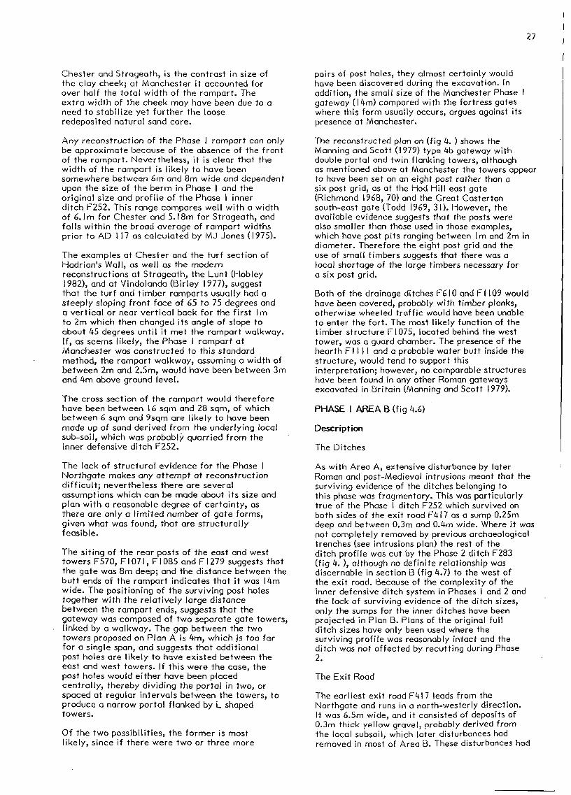
The closest parallels to the Phase I rampart arethe pre-Flavian rampart at Chester (McPeake 1978)and the Flavian rampart at Strageath (FrereI974a). The rampart at Stageath had turf stackrevetments at front and rear, a timber corduroyfoundation and a mixed sand and turf core withlayers of timber strapping. At Chester the turfrevetment at the rear was vertical up to Im andthe front cheek rested at an angle. It too hadtimber foundations and a loose core that was givenextra stability by the use of timber strapping.Although no strapping was observed in the Phase Irampart at Manchester, it is possible that it mayhave existed at a higher level than thatdiscovered, and it is difficult to envisage thenarrow turf stack F369 surviving to any heightwithout an additional means of support.
The other major difference between the Phase Irampart at Manchester and the examples from
THE NORTHGATEPHASE 1
Fig 4-5
27
Chester and Strageath, is the contrast in size ofthe clay cheek; at Manchester it accounted forover half the total width of the rampart. Theextra width of the cheek may have been due to aneed to stabilize yet further the looseredeposited natural sand core.
Any reconstruction of the Phase I rampart can onlybe approximate because of the absence of the frontof the rampart. Nevertheless, it is clear that thewidth of the rampart is likely to have beensomewhere between 6m and 8m wide and dependentupon the size of the berm in Phase I and theoriginal size and profile of the Phase I innerditch F252. This range compares well with a widthof 6.1m for Chester and 5.18m for Strageath, andfalls within the broad average of rampart widthsprior to AD 1 17 as calculated by MJ Jones (1975).
The examples at Chester and the turf section ofHadrian's Wall, as well as the modernreconstructions at Strageath, the Lunt (Hobley1982), and at Vindolanda (Birley 1977), suggestthat the turf and timber ramparts usually had asteeply sloping front face of 65 to 75 degrees anda vertical or near vertical back for the first Imto 2m which then changed its angle of slope toabout 45 degrees until it met the rampart walkway.If, as seems likely, the Phase I rampart atManchester was constructed to this standardmethod, the rampart walkway, assuming a width ofbetween 2m and 2.5m, would have been between 3mand 4m above ground level.
The cross section of the rampart would thereforehave been between I 6 sqm and 28 sqm, of whichbetween 6 sqm and 9sqm are likely to have beenmade up of sand derived from the underlying localsub-soil, which was probably quarried from theinner defensive ditch F252.
The lack of structural evidence for the Phase 1Northgate makes any attempt at reconstructiondifficult; nevertheless there are severalassumptions which can be made about its size andplan with a reasonable degree of certainty, asthere are only a limited number of gate forms,given what was found, that are structurallyfeasible.
The siting of the rear posts of the east and westtowers F570, F1071, F1085 and FI279 suggests thatthe gate was 8m deep; and the distance between thebutt ends of the rampart indicates that it was 14mwide. The positioning of the surviving post holestogether with the relatively large distancebetween the rampart ends, suggests that thegateway was composed of two separate gate towers,linked by a walkway. The gap between the twotowers proposed on Plan A is 4m, which is too farfor a single span, and suggests that additionalpost holes are likely to have existed between theeast and west towers. If this were the case, thepost holes would either have been placedcentrally, thereby dividing the portal in two, orspaced at regular intervals between the towers, toproduce a narrow portal flanked by L shapedtowers.
Of the two possibilities, the former is mostlikely, since if there were two or three more
pairs of post holes, they almost certainly wouldhave been discovered during the excavation. Inaddition, the small size of the Manchester Phase Igateway (14m) compared with the fortress gateswhere this form usually occurs, argues against itspresence at Manchester.
The reconstructed plan on (fig 4. ) shows theManning and Scott (1979) type 4b gateway withdouble portal and twin flanking towers, althoughas mentioned above at Manchester the towers appearto have been set on an eight post rather than asix post grid, as at the Hod Hill east gate(Richmond 1968, 70) and the Great Castertonsouth-east gate (Todd 1969, 31). However, theavailable evidence suggests that the posts werealso smaller than those used in those examples,which have post pits ranging between Im and 2m indiameter. Therefore the eight post grid and theuse of small timbers suggests that there was alocal shortage of the large timbers necessary fora six post grid.
Both of the drainage ditches F610 and F I 109 wouldhave been covered, probably with timber planks,otherwise wheeled traffic would have been unableto enter the fort. The most likely function of thetimber structure FI075, located behind the westtower, was a guard chamber. The presence of thehearth Fl 1 1 I and a probable water butt inside thestructure, would tend to support thisinterpretation; however, no comparable structureshave been found in any other Roman gatewaysexcavated in Britain (Manning and Scott 1979).
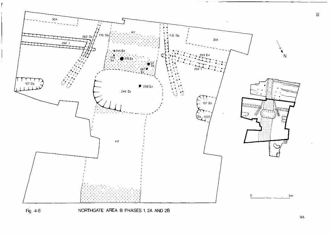
PHASE I AREA B (f ig 4.6)
Description
The Ditches
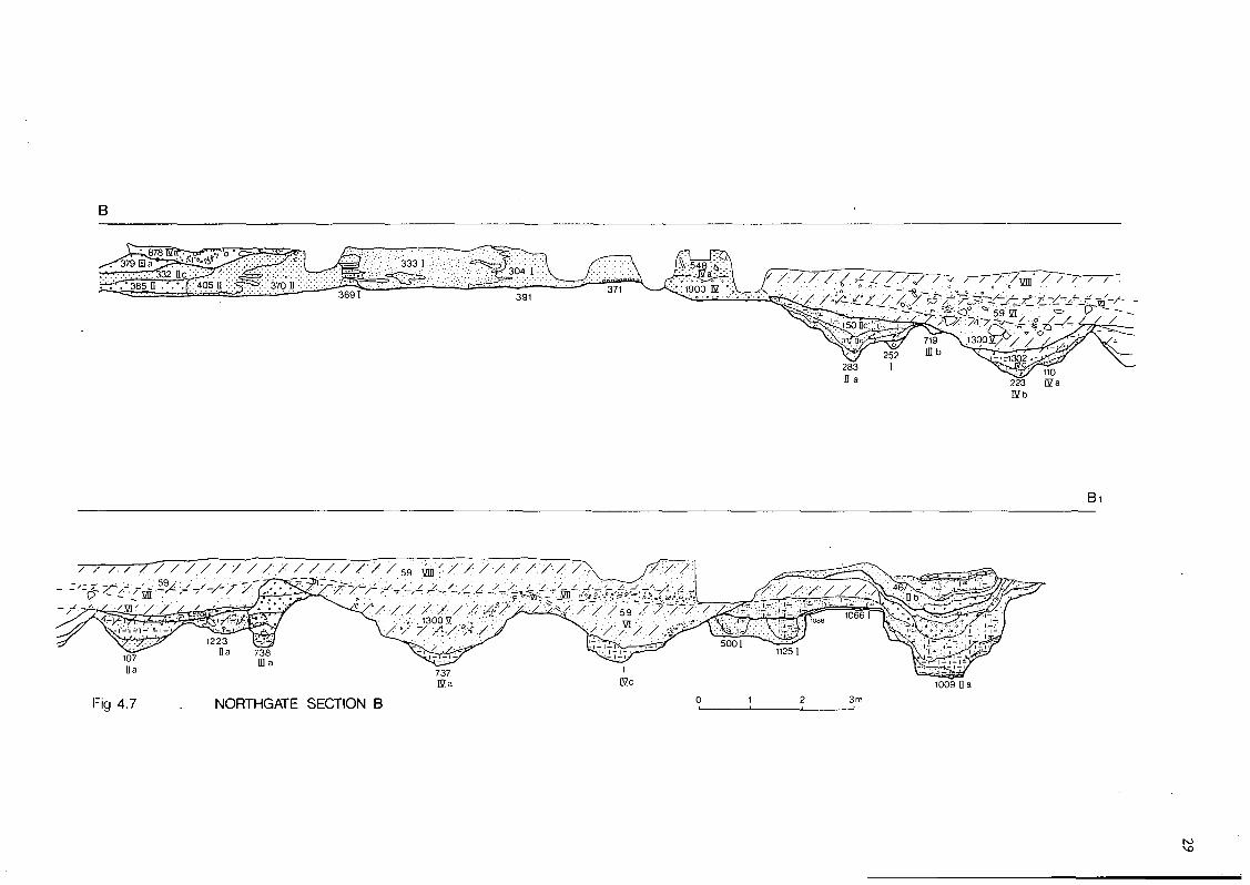
As with Area A, extensive disturbance by laterRoman and post-Medieval intrusions meant that thesurviving evidence of the ditches belonging tothis phase was fragmentary. This was particularlytrue of the Phase I ditch F252 which survived onboth sides of the exit road F4I7 as a sump 0.25mdeep and between 0.3m and 0.4m wide. Where it wasnot completely removed by previous archaeologicaltrenches (see intrusions plan) the rest of theditch profile was cut by the Phase 2 ditch F283(fig 4. ), although no definite relationship wasdiscernable in section B (fig 4.7) to the west ofthe exit road. Because of the complexity of theinner defensive ditch system in Phases I and 2 andthe lack of surviving evidence of the ditch sizes,only the sumps for the inner ditches have beenprojected in Plan B. Plans of the original fullditch sizes have only been used where thesurviving profile was reasonably intact and theditch was not affected by recutting during Phase2.
The Exit Road
The earliest exit road F4I7 leads from theNorthgate and runs in a north-westerly direction.It was 6.5m wide, and it consisted of deposits of0.3m thick yellow gravel, probably derived fromthe local subsoil, which later disturbances hadremoved in most of Area B. These disturbances had
ISJCD
Fig 4-6 NORTHGATE AREA B PHASES 1, 2A AND 2B
5m
GS
Bi
107Da
Fig 4.7 NORTHGATE SECTION B
1009 n a
30
Fig 4-8
also removed any evidence of drainage ditches forthe road in Phase I.
Discussion (fig 4.5)
The Ditches
The silting of F252 between 3m and 4m from thelikely front position of the Phase I rampart,suggests that it had a similar L shaped profile tothe later Phase 2 ditch F283. Given the complexityinherent in this system, it is highly probablethat an additional outer ditch would have beenprovided during Phase I, but traces of it wouldhave been removed by later recutting.
The Exit Road
The same road was observed during the excavationsof the northern vicus in 1972 (Jones and Grealey1974) and 1978 (Jones and Reynolds 1978), and itis highly likely that it formed part of a highwaythat eventually led to the fort at Ribchester, orjoined it near Preston.
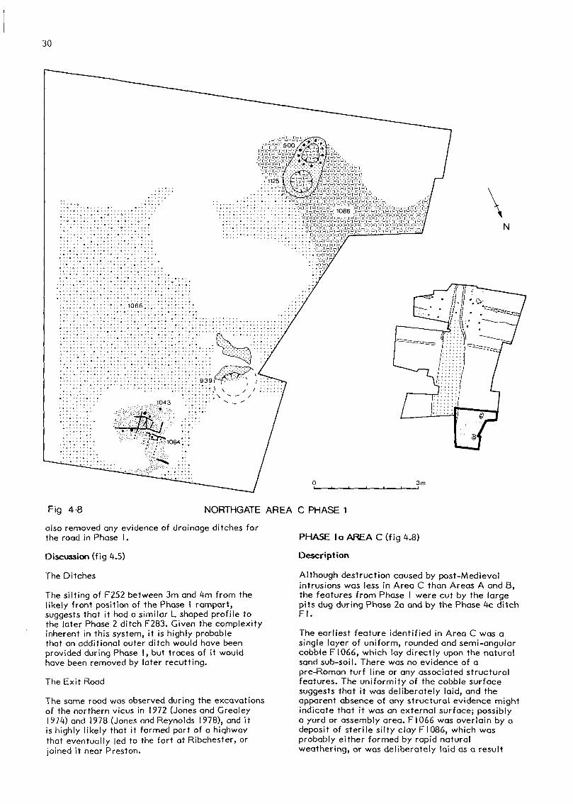
NORTHGATE AREA C PHASE 1
PHASE la AREA C (fig 4.8)
Description
Although destruction caused by post-Medievalintrusions was less in Area C than Areas A and B,the features from Phase I were cut by the largepits dug during Phase 2a and by the Phase 4c ditchFl.
The earliest feature identified in Area C was asingle layer of uniform, rounded and semi-angularcobble FI066, which lay directly upon the naturalsand sub-soil. There was no evidence of apre-Roman turf line or any associated structuralfeatures. The uniformity of the cobble surfacesuggests that it was deliberately laid, and theapparent absence of any structural evidence mightindicate that it was an external surface; possiblya yard or assembly area. FI066 was overlain by adeposit of sterile silty clay FI086, which wasprobably either formed by rapid naturalweathering, or was deliberately laid as a result
N
f ^/ /o
' /'•' i>' l.°
1 1. °1 » °
-IT—
o '
0 '
V0° '
U
. 0
0 ° 0
0 ° .
"1°
« ' « ' • > • > ° . °„'„ 0 ° / 0 0 0 0 0
. ; 4 1 7 \ o o - o o
. „ , 0 ^ o = ^ o o _ o
. ° 00 . ° = ° I ° - ° - ° > ° = 0
1°°x *^ *' \ ^° . "
0 \
° 0 ° 0 \
„ ° ol
° ° ^ 1
5/6 © '•''• ::-:-::: ::. :x::;-:-'304-:-:^ .;........'
* '''"'•"•?* •• •§;;:•;: ^ :..:, /. "•'-^ ~ - • • • - • • : - . • ::;:::•.: ;; x.: xX:^
NORTHGATE AREA A PHASE 2
5m
Fig 4-9

32
THE NORTHGATE
PHASE 2 a
Fig 4-10
of the clearing of a nearby ditch.
Above FI086 was a deposit of compacted sandy clayFI043, cut into which were seven burnt stakes(FI064) driven into the ground to a depth of0.05m; and a series of incisions 0.05m deepcontaining fillings of brown silty loam and whichformed a lattice-like network. The full extent ofthe clay, FI043, could not be determined becauseof later disturbance, but it is possible that itwas part of a working floor associated with theindustrial features F939, F500 and Fl 125. Thefunction of the stakes and incisions could not bedetermined from the small area observed, althoughit is possible that the incisions may have formedpart of a framework for a wooden floor.
Three small industrial features were also observedin Area C. F939 lay near the north-west corner of
the area, and was cut to the north by the Phase 2apit F830. It survived to a depth of 1.2m and itsoriginal diameter is likely to have been 0.25m. Itwas lined with a stiff grey clay to form a bowlwhich was overlain with a mixed deposit ofcharcoal and burnt clay which was, in turn, cappedby a deposit of silty clay. Both these depositsfilled the bowl created by the clay lining andprobably represent the waste deposits which weredumped into the bowl after it went out of use. Thesandy sub-soil around F939 was discoloured by heatto a depth of 0.15m. The other two industrialfeatures Fl 125 and F500 were both located at thesouth corner of Area C, and were contained withina single pit which was lined with hard packedburnt clay. The bowls of Fl 125 and F500 were bothfilled with a deposit of sandy silt with charcoalinclusions, which was similar to the deposit whichfilled F939. A single row of stake holes,
33
surviving to a depth of 0.12m were located aroundthe periphery of F500.
Discussion
It is likely that the Phase I deposits in Area Crepresent part of some form of extra muralsettlement which was contemporary with Phase I ofthe fort defences in Areas A and B. In 1972Professor Jones (Jones & Grealey, 1974, 41-8)discovered during excavations in the vicus,evidence of an early defensive system that wasprobably contemporary with these deposits. Thefinds from Area C, particularly the industrialfeatures, although fairly meagre and inconclusive,suggest that the extramural settlement may havebeen a military annexe. The three industrialfeatures are probably the remains of small hearthsthat may have been used in conjunction with amould (1981, 1329 & 3098) discovered in this area,possibly to produce metal horse trappings.
Dr Cleland (University of Cambridge) comments thatthe reddish colour of the clay, which lined thesefeatures, shows that the hearths were fired underoxidising conditions, and that their purpose wasthe production of heat rather than the conditionsrequired for the reduction of ore. This opinion issupported by both the absence of any slag on thelining of the hearths, or in their immediatevicinity. The colour of the fired clay of thelinings would suggest that the hearths were nottaken to a very high temperature and it ispossible that they were used for the remelting ofan easily handled non-ferrous metal/alloy, such aslead.
PHASE 2a AREA A (fig 4.9)
S Bryant
Description
The Northgate
The Phase I post hole, F107 I, at the back of the
Ci
west tower was replaced by FI072, and its oppositenumber FI279 was replaced by FI274. Both thereplacement post holes were of similar dimensionsand contained a similar filling to theirpredecessors. F1075, the structural feature behindthe west tower, was burnt down and the charredremains of its post and stakes were overlain by alayer FI005 formed from the burnt remains of thebuilding. As with Phase 1 there was no evidencefor the gateway passage being metalled.
The Rampart and Intervallum Road
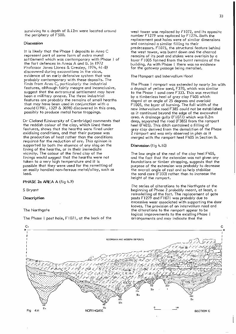
The Phase I rampart was extended by nearly 3m witha deposit of yellow sand, F370, which was similarto the Phase I sand core F333. This was revettedby a timberless heel of grey clay F405 whichsloped at an angle of 25 degrees and overlaidFI005, the layer of burning. The full width of thenew intervallum road F385 could not be establishedas it continued beyond the edge of the excavatedarea. A drainage gully (FI077) which was 0.2mdeep, separated the road (F385) from the rampartheel (F405). This ditch contained a filling ofgrey clay derived from the demolition of the Phase2 rampart and was only observed in plan as itmerged with the rampart heel F405 in Section B.
Discussion (fig 4.10)
The low angle of the rest of the clay heel F405,and the fact that the extension was not given anyfoundations or timber strapping, suggests that thepurpose of the extension was probably to decreasethe overall angle of rest and so help stabilisethe sand core (F333) rather than to increase theheight of the rampart.
The series-of alterations to the Northgate at thebeginning of Phase 2 probably meant, at least, aremodelling of the fort. The replacement of gateposts FI279 and FI07I was probably due toexcessive wear associated with supporting the doorleaves. The provision of an intervallum road andthe alterations to the rampart appear to belogical improvements to the existing Phase Iarrangements and may indicate that the
Rg 4.11 NORTHGATE SECTION C

34
refurbishment was part of a shift towards theestablishment of a permanent fort.
PHASE 2a AREA B (fig 4.6)
S Bryant
Description
The Defensive Ditch System
The Phase I inner ditch (F252) was recut I rnfurther towards the north rampart. The Phase 2recut (F283), which survived better than F252, hada depth of 0.8m and width of 3m. In Section B theditch bottom was filled with a natural silt ofsandy loam derived from weathering of the sandsub-soil of the ditch sides. Above this was adeposit of grey clay representing a deliberatebackfilling of F283 with rampart material at theend of Phase 2. In section C (fig 4.1 I) there wasno primary silt, and F283 was filled completelywith the same deposit of grey clay. To the eastside of the exit road, F4I7, the ditch (F283) wasobserved to turn at an angle of 120 degrees fromits original direction and run for 2.4m beforebeing cut by the Phase 3b ditch F7I9. Only the0.2m deep sump of this ditch survived in theflanking element and it contained a primary siltof silty clay. Evidence for a correspondingflanking element on the west side of the exit roadF4I7 was destroyed by intrusions, but aconjectural line has been included in figure 4.6.
An outer ditch, FI07, lay 6m north of F283, andterminated 6m from the west side of the exit road.The most representative profile of this outerditch, FI07, was in Section C (fig 4.1 I), where itsurvived to a depth of 1.4m and a width of 1.8m,with a sharply V shaped profile cut into thesandstone bedrock. It contained a primary fillingof red sandy loam formed from the naturalweathering of the rock, above which were fourlayers of yellow gravel that were virtuallyidentical in composition and probably resultedfrom a deliberate backfilling of FI07. A depositof grey clay overlaid the gravel, and probablyformed part of the same Phase 2 demolition depositwhich filled F283.
A second outer ditch, FI223, was observed 1.9m tothe north of FI07 in Section B. It contained anatural primary filling of sandy silt-loam, whichwas also overlain by a sandy loam. There was noclear relationship between FI07 and FI223, butthey probably formed a contemporary double ditcharrangement. FI223 was not observed to the east ofthe exit road in Section C because of the size ofthe excavated area.
Traces of a central ditch, F249, were observed 8mnorth of the Northgate. Later intrusions from thePhase 5 sunken features, F229 and F290, and thePhase 3 ditch, FI76, had destroyed virtually alltrace of its extent and internal morphology.It was marked, however, by series of isolatedsloping depressions which were filled by thedeposit (FI50) associated with the end of the
Phase 2 fort. The plan of h249 on Figure 4.1 givesits likely maximum extent. Six post holes werelocated within and to the south of F249. Five ofthem (F245, F275, F276, F52 and F287) were cutthrough the exit road F4I7. They all contained afilling of dark brown sandy loam. The largest wasF276 at 0.6m; the others were between 0.3m and0.4m deep. F258, contained a filling of dark brownsandy loam, lay within the ditch F249, and waspartially cut by the Phase 3b ditch FI76.
Discussion (fig 4.10)
Although there was insufficient evidence todetermine the exact position of the terminal endsof the flanking elements to F283, due to the factthat they did not directly link up with the outerditch F I 07, it has been assumed that theyterminated between FI07 and the central ditchF249. As with most of the ditch phases in Area B,the amount of later ditch recutting makes itdifficult to stratigraphically link contemporaryseparate elements of a ditch system together.The fact that F283, FI07 and F249 were all sealedby deposits from the end of the Phase 2 fort andtheir spatial relationship to one another,suggests that they were all part of a unitarysystem. When observed together in figures 4.6 and4.9, the various elements of the arrangement makea logical, if unusual, system.
The closest parallel is with that of the Claudianfort of Hod Hill (Richmond 1968) where thedefences consisted of two inner ditches, Im apart,and linked at the entrances with a layout similarto that of F283 and FI07 above, although they arenot directly linked together. Hod Hill also hadtutu I i at the south gate and the east gate whichwere designed to prevent a direct assault. F249probably acted as a tutulus in much the same wayas those at Hod Hill, with the two flankingelements of F283 funneling the diverted attackersinto two narrow passageways either side of theNorthgate entrance. There was no evidence of anadditional outer ditch at Manchester, although onemay have been removed by the Phase 4c outer ditchFl. Broadly similar ditch systems to those foundhave been discovered at several Flavian forts,that is forts with date ranges similar to those ofthis phase, at Crawford, Lanark (RCAHM 1978 no255) and Cardean, Angus (Robertson 1971), butexcavated examples of tutuli in Britain areunknown from this period.
The apparent random distribution of the post holesassociated with F249 is due to the amount ofdisturbance from later ditches and previousarchaeological trenches in the surrounding area.They may have been either supports for a bridgeacross F249, part of an additional defence ofsharpened stakes, or part of a double palisaderunning between F249 and the Northgate. Of thesethree possibilities, one of the latter two is mostlikely, as the provision of a bridge across F249would not make any tactical sense to the Phase 2defensive system, although such bridge systemsappear to have been common in Germany.

35
PHASE 2a AREA C (fig 4.12)
S Bryant
Description
Four large oval pits were discovered in Area C.F830, located in the north-west corner, was cut bythe north and west baulks. It was 1.2m deep with aU shaped profile and a flat bottom, which was cutinto the natural sand sub-soil. The bottom fillingof F830 was a yellow sand derived from weatheringof the pit sides. Above this were three similarlayers of grey silty loam, which were probablyformed by deliberate backfilling. Two of thelayers were also spread across the northern partof Area C, sealing the Phase I deposits.
FI009 and FI02I were both situated in the centreof Area C, and were separated by a baulk 0.1 mwide; both had a U shaped profile with a flatbottom cut into the natural sub-soil in a waysimilar to F830. The filling of FI009 and FI02Iwas also similar to that of F830, although therewas no priinary fill of sand and the backfillingwas of sandy silt rather than of silty loam. This
deposit, along with several other layers of sandand gravel, was also spread around FI009 andFI02I, but it was not possible to determine theprecise sequence of backfilling of the two pitsbecause of disturbance caused by the Phase 2bindustrial feature, F467.
Fl 136 was located at the south-west corner of AreaC. It was similar in form to the other three pitswith a U shaped profile and a flat bottom, and itsfilling was the same as FI009 and FI02I. It wastruncated by the Phase 4c ditch Fl, However, whichhad cut away all evidence of its possible reuse asan industrial feature in Phase 2b.
The Phase 2a exit road (F273) was also located inArea C. It consisted of 0.4m of yellow gravelwhich ran over the Phase I deposits, a fact whichmay suggest that an earlier road existed to theeast of F273 during Phase I. As no road survivedfrom the Northgate in Area A to the edge of thesite in Area C, it was not possible to answer thisquestion.
Fig 4-12 NORTHGATE PHASE 2a AREA C

36
830 Da
Fig 4-13
Discussion
NORTHGATE
The four large pits were probably the result ofgravel extraction activities, as gravel was neededfor the exit road (F273) and perhaps in theindustrial processes connected with the Phase 2aindustrial features. The deposits which were usedto backfill the pits and spread over Area C were
SECTION D
probably derived from the industrial activities. Acomparison between the road in section D (fig4.13) to a section drawn 15m further north (Jones& Grealey 1974, fig 7, section A-A), suggests thatF273 is probably equivalent to the latest roadlevel in Section A and although larger than F868,it is probably contemporary with it. In addition
THE NORTHGATE
PHASE 2b
•v..
Fig 4-14

37
it is possible that the two resurfacings of theroad in section A-A, 42 and 44, which extendedinto the side ditch 48a, are contemporary withthe Phase 2b resurfacing FI307 and the Phase 3resurfacing F752 in Section D.
PHASE 2b AREA A (fig 4.9)
S Bryant
Description
Overlying F1005 was a thin patchy gravel surfaceF385.
Discussion (fig 4.14)
F385 clearly represents the resurfacing of theroad that ran around the inside of the fort.
PHASE 2b AREA B (fig 4.6)
S Bryant
Description
The phase commenced with the cutting of the Phase2a inner defensive ditch F7IO, which followed thesame line as the earlier ditch F283 but lay 0.65mcloser to the exit road and extended 3m furthertowards the rampart. F7IO had a V shaped profileand, where it had not been cut away by laterfeatures, was 0.4m deep and filled with a greyclay derived from the demolition of the Phase 2rampart.
Discussion
The preceding defensive ditch system appears tohave remained largely unchanged and, on theevidence of this recut, maintained.
PHASE 2b AREA C (fig 4.15)
S Bryant
Description
The western side drainage ditch, F868, to thePhase 2 road was V shaped, 1,2m wide and survivedto a depth of 0.55m. It cut through the Phase 1and Phase 2a deposits associated with the largepits and the primary filling of F868. This fillingwas overlain by a deposit of brown sandy loam,also formed by natural erosion that led to agradual accumulation of soil. The effect of thisprimary and secondary accumulation was to raisethe level of the ditch bottom by 0.3m and move it0.3m to the east, resulting in a shallower Ushaped profile.
Although there was no evidence that Phase 2b inArea C was contemporary with the Phase 2b ditchresurfacing (F7IO) in Area B, it had been includedwith the latter because it antedates Phase 3a inAreas A and B.
Two industrial features, along with theirassociated structures and working surfaces, werediscovered. Part of the deliberate backfilling ofF830 was removed and the resulting U shaped
shallow pit (r-747) was lined with a gravel depositwhich was in turn overlain by a grey clay deposit.To the south and west of F747 were ten stake holeswhich had been burnt in situ. They were cut intothe grey clay to a depth of 0.2m. It is possiblethat more of them may have existed to the east ofF747, but the edae of the feature was cut by theconstruction trench F73I for the Phase 3a buildingF727. The second industrial feature F467 waslocated 2m south of F747 and, like F747, it hadcut through the backfilling of the Phase 2a pits,in this case FI009 and F1021. It had a lining ofyellow gravel, which was overlain by a deposit ofgrey clay.
This clay deposit covered a slightly concave area5m by 3m, above which was a thin layer of burntmaterial overlain by a silty sand deposit, whichwas in turn overlain by a thin layer of gravel,and finally another layer of burnt material. Thesedeposits probably represented at least twosuccessive firings of the industrial feature, withan intermediate dumping of refuse, and a reliningwith gravel.
A spread of compacted gravel (F86I), 0.2m thick,was discovered in the northern half of Area C. Itwas cut to the east and west by the Phase 3abuilding construction trenches, F73I and F732.F861 was probably an internal or external workingsurface associated with F747 and F467. Nostructural features were found associated withF861, but a layer of burnt clay and daub aboveF86I may represent the demolition of some sort ofbuilding.
The exit road was extended with a deposit ofyellow sand and gravel, FI307, over the drainageditch F868 in Phase 2b.
Discussion (fig 4.14)
In broad morphology and in type of filling, thesefeatures are very similar to others discoveredelsewhere in the vicus (Jones and Grealey 1974,148-53) which have been interpreted as ironfurnaces.
PHASE 2c AREAS A and B (fig 4.7)
S Bryant
Description
A series of three types of deposit appear to haveresulted from the demolition of the Phase 2 fort:firstly, those representing the burnt remains ofthe fort's timber structures; secondly, a spreadof clay derived from the slighting or flatteningof the rampart; and thirdly, a deposit ofoccupation refuse. Together, these formed adistinct layer over much of Areas A and B.
Most of the Northgate area was covered with aspread of charcoal and burnt daub (F334). Severaltraces of burnt timber, 2.5m long and with adiameter of 0.12m to 0.15m, were discovered aspart of the deposit in the east drainage gullyF610. Also within F6IO was a deposit of charredgrain. The charcoal spread (F334) was almostcertainly derived from the burnt timber structure

38
Fig 4.15 NORTHGATE AREA C PHASE 2b
of the Northgate, and the presence of the grainsuggests that a granary probably stood near to thegateway prior to its destruction.
A deposit of grey clay (F332) formed by thedemolition of the Phase 2 rampart was spread overthe Northgate area, overlying F334 and sealing allof the Phase 2 features which were not sealed byF334. This clay also spread into the innerdefensive ditch F283 and F7IO, as far as the outerdefensive ditch FI07, to the east of the exit roadF4I7, and sealed the gravel backfilling of FI07,which had presumably taken place immediately priorto the clay dumping.
A mixed deposit of grey silty clay FI50 andcharcoal F253, which contained moderate amounts ofbone and pottery, was dumped in front of theentrance to the Phase 2 Northgate, sealing theclay F332 in the inner ditch F283 and filling thecentral ditch F249.
Discussion
The extent and nature of the demolition depositsmakes it clear that the fort was systematicallyreduced. It is well known that the Roman armydeliberately destroyed abandoned forts in order todeprive the enemy of a useful and prepared site.
A sequence of burning followed by extensive claydumping was also observed during the 1975 DukePlace excavations at the north-west corner of thefort (see above), and by Petch (1954, 29-30). TheDuke Place excavations also produced evidence ofan extension to the fort westwards in Phase 3which, together with the demolition, suggests aphase of abandonment between Phases 2 and 3 beforea new larger garrison was installed in Phase 3.
A similar group of deposits was also observed atthe nearby Peak fort of Brough-on-Noe (Jones andWild 1969); this was thought by the excavators tohave arisen as a result of the deliberatedemolition of the fort, which was abandoned atmuch the same time as Manchester may have been.
N
NORTHGATE AREA A PHASES 3a AND 3b
5m
Fig 4-16GS TR MW MON
oovo
40
THE NORTHGATE
PHASE 3 a
Fig 4-17
PHASE 2c AREA C (fig 4.15)
S Bryant
Description
Filling the top of the earlier pit (F747) was asilty clay containg isolated pebbles and somecharcoal.
Discussion
The filling of this pit may be a mixture of theclay and charcoal demolition debris found in areasA and B.
PHASE 3a AREA A
S Bryant
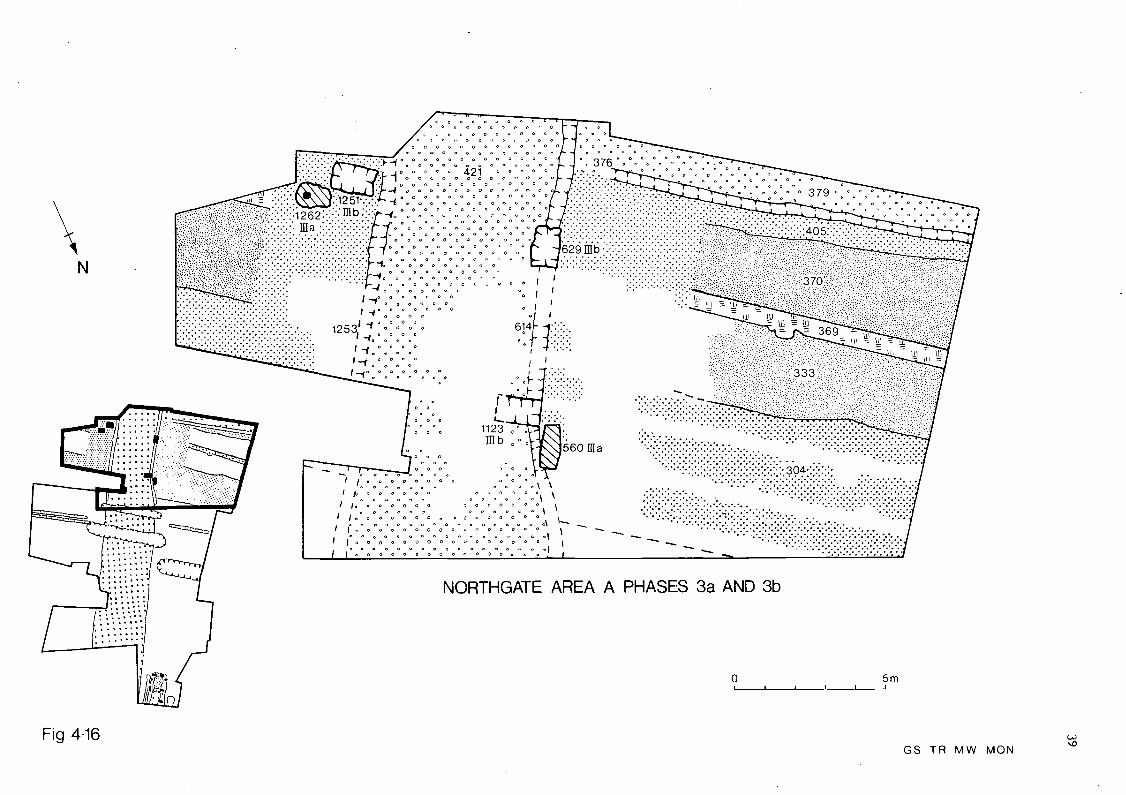
Description (fig 4.16)
The Northgate
The surviving post holes of the Phase 3 gatewaysrepresent two separate phases of the same gatetype. Two post holes, F560 and FI262, belong tothe Phase 3a gateway. A third probably existedadjacent to the Phase 3b post pit (F629) but wasdestroyed by the Phase 4 stone foundations, and afourth probably existed opposite and outside theexcavated area. F560 was located at the front ofthe entrance on the west side. It survived to adepth of 0.5m and contained a uniform filling ofsandy loam. There was no sign of a post pipe and
it is therefore likely that the filling representseither rapid silting or deliberate backfilling,once the post had been removed at the end of Phase3a. FI262 was located at the back of the entranceon the east side of the passage way. It was 0.56mdeep and contained a post pipe 0.27m in diameterand a filling of clay loam with silty clayinclusions. This suggests that the post wasprobably sawn off, or had rotted away by the endof Phase 3a.
In Phase 3a the gravel exit road (F42I) wasextended into the fort. In the gateway passsage itwas 5.2m wide, and consisted of a uniform depositof yellow gravel with a maximum thickness of 0.4m.
Two new drainage ditches were also dug. FI253 was0.5m deep and contained a filling of stiff pinkclay and red sandstone fragments deposited duringthe construction of the Phase 4 gatewayfoundations. The other ditch, F6I4, survived to adepth of 0.6m. In Section A, F6I4 has a dualprofile but as this was only present close to thesection it was not possible to determine what itrepresented. In general F6I4 contained a uniformfilling of grey silty loam, which probably wasformed by deliberate backfilling at the beginningof Phase 4 or by rapid silting; however, the depthof the deposit makes the former seem more likely.
The Rampart and Intervallum
In Phase 3a the rampart was extended by 4m oneither side of the entrance, with a deposit ofgrey clay, the same as F304 and F405, to meet up

5m
Fig 4.18 NORTHGATE AREA B PHASES 3 AND 4
42
with the Phase 3a gateway revetment represented bythe post holes F560 and FI262. The rest of the newrampart incorporated the foundations of theearlier Phase 2 rampart, as is suggested by theposition of the Phase 3a intervallum road (F379),which was the same as the road in Phase 2. Thisroad (F379) was of the same material, that islocally derived gravel, as the Phase 2 road F385.It overlaid the demolition deposit (F332) fromPhase 2 and had a maximum thickness of 0.4m .Asmall drainage gully (F376) was situated betweenthe intervallum road and the rear of the Phase 3arampart. As with the Phase 2 rampart drain, it wasnot visible in Section A because it had been cutby the Phase 4 intervallum road F878.
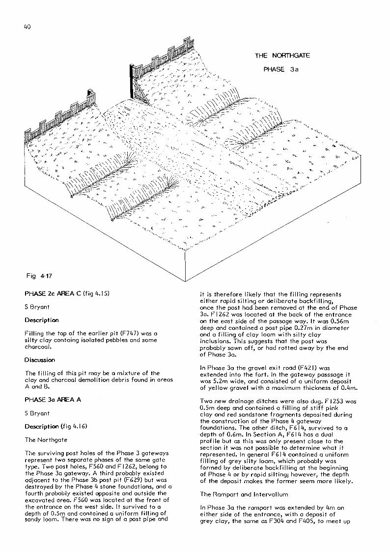
Discussion (fig 4.17)
As with the Phase I and 2 gateway plans, theamount of disturbance caused by later intrusions,particularly the Phase 4 foundations which cutthrough the centre of tne Phase 3 passageway,makes a precise interpretation of the Phase 3aplan difficult. However, given the position and
number of posts on either side of the passageway,there are two possible layouts to the gate.
The gateway was either a four post single portalstructure, without towers and with a gate at thefront of the entrance, Manning and Scott type IA(Manning and Scott 1979, 19) or a double portalgateway without towers but with additional postsdividing the passageway into two, Manning andScott type IB (op cit, ibid). Of these twoarrangements the latter, type IB, is unlikely, asat least one of the additional pestholes wouldhave been found during the excavations. The typeIA arrangement has therefore been adopted forfigure 4.17, although the width of the Phase 3passageway at 6m is larger than the average ofbetween 4m and 4.6m for excavated examples of typeIA gateways (Manning and Scott 1979, 31-4).
This change to a similar type of gateway in Phase3a is in keeping with the trend towards lesselaboration in gateway form during the 2nd centurynoted by Manning and Scott (op cit, 29).
Fig 4.19 NORTHGATE AREA C PHASES 3a AND 3b

43
The reinstatement of the Northgate, the rampart,and the intervallum road in the same positions asin Phase 2, suggests that most of the ground planof the Phase 2 fort had survived the deliberatedestruction of its superstructure, so that thefort was still sited in such a position as todominate the river crossing and the road junction.This new fort, as is proved by the Duke Placeexcavations, was about 2 acres (0,9ha) larger thanthe earlier forts. This expansion is probably dueto a change in garrison from one of 480 infantryto a mixed unit of 608 men which contained around128 cavalry (Breeze and Dobson 1978, table 12).Its larger and more substantial gateway andrampart indicate a further move towards moredefensive thinking in fort design, and towards agreater permanence.
PHASE 3a AREA B (fig 4.18)
S Bryant
Description
A new inner ditch F224 was dug 2.2m north of thePhase 2 inner ditch F283. Only a sump 0.2m deepsurvived on the east side of the exit road F42I,and on the west side it was completely removed bythe Phase 4b ditch F223. No relationship wasobservable in Section C (fig 4.1 I) between F224and the Phase 3b ditch sump F7I9. However, thefact that F224 was cut by the Phase 3b ditch FI76(fig 4.18), suggests that they may have formed acontemporary double ditch arrangement thatantedated F719.
The sump of F224 contained a grey clayey silt. Anouter ditch (F738) was observed IOm north of thefort rampart, west of the exit road (F42I). It cutthe secondary filling of FI223, and was cut inturn by the Phase 4a ditch (F737) to the north andby the Phase 5 sunken feature F804 to the south.The extent of the disturbance to F738 by these twofeatures severely truncated its profile, butenough survived to determine its shape andapproximate dimensions. The profile was U shapedand survived to a depth of 1.3m with a flat bottom0.4m wide. The original width of F738 is thereforelikely to have been between 3m and 4m. The primaryfilling of F738 consisted of a sandy silt loamderived from natural weathering of the ditchsides; above this were four separate layers ofvarying textures, which all appeared to be formedby a deliberate backfilling which probably tookplace at the end of Phase 3b. F738 was not locatedeast of the exit road (F42I) because of thelimitations of the excavated area.
A new exit road (F421) was constructed over therefuse deposit (FI50). It consisted of locallyderived yellow gravel with a maximum thickness of0.5m, and only survived for a total length of 5min Area B.
Discussion (fig 4.17)
The surviving evidence suggests that a straightforward double ditch system, with uninterruptedaccess to the Northgate via the exit road (F42I)existed during Phase 3a.
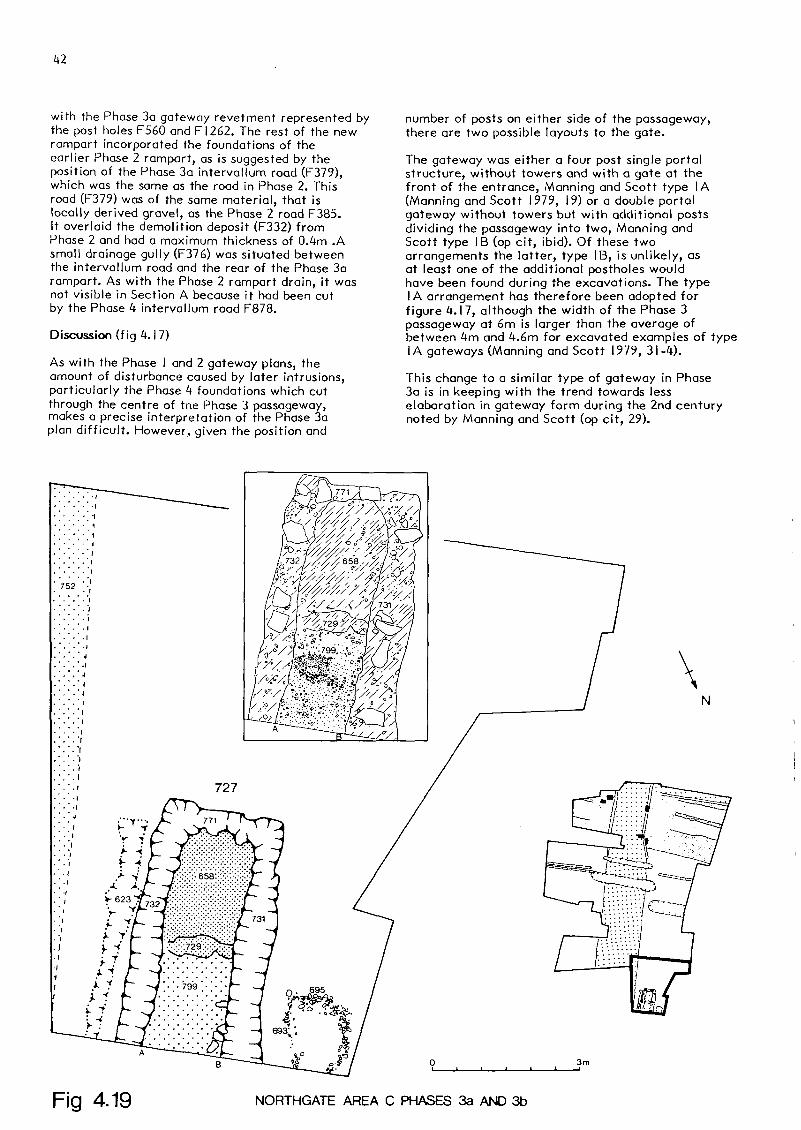
PHASE 3a AREA C (fig 4.19)
S Bryant
Description
Part of the foundations of a small building (F727)were located in the northern half of Area C. Threeconstruction trenches (F731, F732 and F77I) wereidentified as belonging to F727. They allcontained a filling of grey silty clay, togetherwith sandstone fragments and pebbles. The fillingof F732 extended to the east, covering most of thePhase 2c road extension (FI307). A floor ofcompacted yellow gravel (F799) was observed insidethe building, together with the foundations of aninternal partition wall, F729, to the south ofwhich lay another floor (F658) of compacted yellowclay 0.05m deep. The foundation trenches weretopped in places by blocks of sandstone rubble. Tothe west of the building the hollow left by thePhase 2b feature F747 was filled with a spread ofcobble F693 and F695.
Discussion
The presence of the sandstone blocks on thefilling of the construction trenches for F727,suggests that the initial Phase 3a building wasprobably either of stone construction or had atimber frame supported by stone dwarf walls.However, the fact that the timber beam slot (F623)replaced the construction trench (F732) seems toindicate that the second alternative is the mostlikely.
Taking into account the size of the two smallrooms in F727 in Phase 3a, its original length islikely to have been about 6m, and its width 3m,giving it a width to length ratio of 1:2.
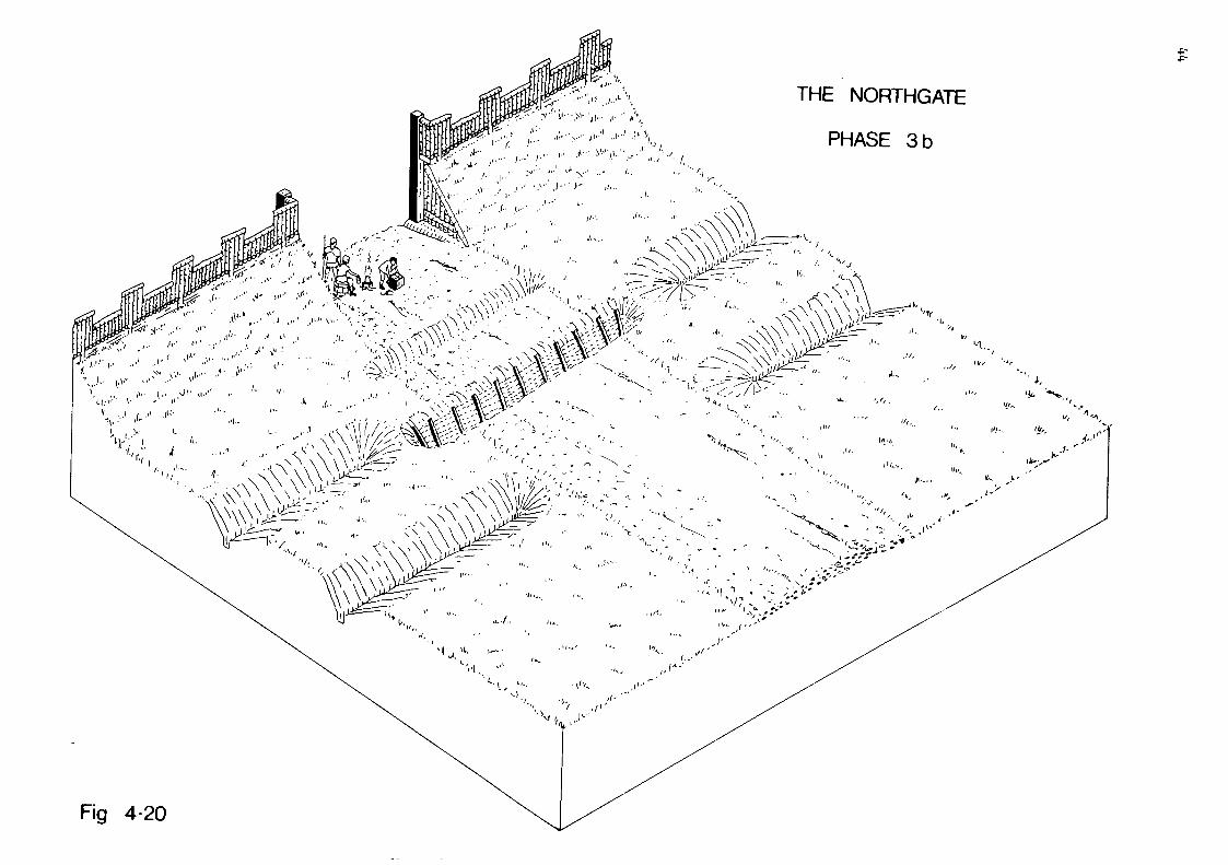
PHASE 3b AREA A (fig 4.20)
S Bryant
Description
The two Phase 3a post holes (FI262 and F560) wereboth replaced at the beginning of Phase 3b, byFI25I and Fl 123 respectively. A third post hole(F629) was also dug on the same side as F1123 but5.3m further to the south. Fl 123 survived to amaximum depth of 1.3m, and contained a uniformfilling of grey silty loam which probablyrepresents a deliberate backfilling, once the postwas removed. F629 was 1.6m deep and also containedwhat appeared to be a deliberate backfilling ofgrey silty loam. FI25I was 1.8m deep and containeda bottom filling of brown sandy loam 1.2m deepwhich was overlain by a mixture of red sandstonefragments. The earlier ditch (F6I4) was filledwith a brown silty loam (FI084) semi angular rivercobble and stiff pink clay.
Discussion
The lower layer is probably the result ofdeliberate backfilling, whilst the upper layer wasprobably formed, like the similar filling of thenearby drain FI253, during the construction of thePhase 4 stone gateway.
THE NORTHGATE
PHASE 3b<•, ^:....- /...- )•••• " • - * • " s > j ! > • • " . - • ' ' .1..;'•'• i
(,. i - -1 j- >!•• ' y -^rfc »~- -. •.'(1 ••• • ' ! - ' * - ' - v; -
Fig 4-20

'•:£&*)
• '. • <=//• .^y.-. -. ; ••S.'.c^0 -4?-. •• O. .CO. «^TA »r /-> '/^N ' '
fStfx--. *0' 59 / Q / .OQ<n-o^.O
NORTHGATE SECTION E
PHASE 3b AREA B (fig 4.18)
S Bryant
Description
A recut (F7I9), to the west of the exit road ofthe Phase 2a inner ditch F224, was observed 0.5mto the south, and, as with F224, only the sumpsurvived. In Section B (fig 4.7) it was cut by thePhase 4b ditch F223, and its sump contained anatural filling of grey silt. In Section C (fig4.I I) the filling of F7I9 was very similar toF224, and it was not possible to define anyrelationship between the two ditches (see below).There was no evidence that the Phase 3a outerditch F738 was recut during Phase 3b, althoughthis may have been obscured by the Phase 4a ditchF737 to the north of F738. Two ditches (F67 andFI76) were dug across the Phase 3a exit road F42I.F67 had a V shaped profile 0.8m deep, andcontained a bottom filling of sand and gravelformed by the weathering of the ditch sides;overlying this was a grey silty clay formed by theweathering of the Phase 2 refuse deposit (FI50)which F67 cut through.
Above the silty clay was a deliberate backfillingof clean sand and gravel, which formed a base fora layer of large stones and boulders mixed withgravel. The latter deposit almost certainlyrepresents a reinstatement of the exit road (F42I)across F67, at the beginning of Phase 4a. As wouldbe expected, some subsidence of this layer wasnoticeable and an attempt had been made to levelit up with a further deposit of gravel. FI76 had aU shaped profile with straight sides and a flatbottom 1.5m deep by 1.6m wide. It was cut by thePhase 4b ditch (F223) and the Phase 5 sunkenfeature, F229 (fig 4.21). The primary bottomfilling of F 176 was similar to that of F67. Anumber of wooden stakes were preserved in place inthe primary filling of FI76. They were arranged inpairs 0.8m apart, angled in a V and were parallel
with the ditch sides, and driven between 0.2m and0.3m into the base of the ditch. Above the primaryfilling of FI76 was a deposit of sand and gravel,which was overlain by a layer of large stones andcobbles similar to the upper filling of F67. Thisrepresents a reinstatement of the exit road (F42I)contemporary with the backfilling of F67. However,this layer petered out towards the edge of theexit road (F42I). Here the primary filling isoverlain by deposits from Phases 5 and 6; it istherefore certain that parts of F176 which werelargely backfilled in Phase 4a, were allowed tosilt up naturally.
The fact that the stakes were not visible in thesecondary filling of FI76, suggests that they mayhave been sawn off prior to the reinstatement ofthe exit road.
Discussion
The most likely function of the stakes in F 176 isas a revetment, to prevent the steep sides ofloose gravel from collapsing. A similararrangement has been observed at Melandra,Derbyshire (Webster 1971).
F67 was obviously too small to fulfil anydefensive function, and was likely to have beendesigned merely as a means of preventing access tothe Northgate. FI76, on the other hand, is moresubstantial and would have formed an effectivedefensive barrier. The digging of F67 maytherefore have been an unsuccessful intermediatemeasure.
The closing of the Northgate during Phase 3bsuggests that it was superfluous to therequirements of the fort commander, or that hewanted to limit communications between the fortand the extra mural settlement to the north. Theeventual digging of FI76 indicates that thedefensive factor was borne in mind but is unlikelyto have been the original motive for closing the

entrance, given the insubstantial nature of F67.As the main gate to the fort was on the easternside, the closing of the Northgate does not mean,in itself, that the fort was abandoned.
PHASE 3b AREA C (fig 4.19)
S Bryant
Description
Building F727 was extended to the east, and itseastern wall replaced by a beam slot (F623) cutinto a spread of road material (F752). This slotwas filled with a sandy loam, little differentfrom the layers above, and it contained in placesa black silty loam 0.02m thick, that probablyrepresents part of the .original beam. A new sandyfloor (F566) was laid, which ran across the lineof the original western wall (F73I).
Discussion
Most vicus buildings have their axis at rightangles to the road (Salway I960, 10) but where theaxis is parallel to the street their size isusually much larger than F727 (Richardson 1936).This building is also considerably smaller thanthe vicus buildings found during the Manchester1972 excavations (Jones and Grealey 1974) and the1977-8 excavations (Jones and Reynolds 1978),which were interpreted by the excavators asdomestic living quarters and industrial workingsheds. The maximum internal ground floor area ofF727 is 18 sq m, and even if there were additionalstoreys it would have been barely sufficient asdomestic living quarters or for industrial workingprocesses. The most likely use for building F727therefore, considering its size, orientation, andposition, is as a small shop even though no clearconfirmatory evidence has come from the artefactsfound within or in the vicinity of the building.
PHASE 3c AREA A
S Bryant
Description
Cut into FI084 was a small gulley, FI063, filledwith silty loam. This gulley only appeared inSection A, (fig 4.4).
Discussion
The gradually silted up ditch was replaced by agulley, which itself silted up before thebeginning of Phase 4.
PHASE 3c AREA C
S Bryant
Description and Discussion
The Phase 3b building was overrun by a demolitiondeposit (FI90I) of sandy silt, containing charcoaland flecks of daub. This deposit also overran theedge of the earlier main northern road.
The building had clearly been demolished, possiblyto make way for the Phase 4c roadway.
PHASE Ita AREA A (fig 4.22)
J Walker
Description
The Northgate
The construction of the Phase 4 Northgate waspreceded by the systematic demolition of the Phase3b timber gate. The posts were removed and thepost pits backfilled (see fig 4.16). There was noevidence to suggest a phase of abandonment betweenPhases 3 and 4.
The Phase 4 Northgate was represented by thefoundations of a twin-arched stone tower, andthese consisted of three separate elements. Thewest pier (F309) was 7m long and between 1.6m and1.8m wide, with end projections which increasedits width to 2.8m. Its foundation was 2.0m deepand consisted of layers of soft sandstone (FI900)derived from the local bedrock and courses ofstiff pink clay mixed with larger river cobble.The east pier (F305) was 7.3m long by 1.8m widewith a protection at the rear which increased thewidth to 3.6m. Its foundations were identical tothose of F309. The central spine (F307) was 6.2mlong by 2.2m wide, and was recessed 0.5m behindthe front of the gateway. Its foundation were thesame as F305 and F309, but at 2.5m were 0.5mdeeper. Very little survived of the Phase 4 roadlevels inside the gateway, because the latestRoman levels in this area had been destroyed bythe construction of the Hanoverian terraced houseson the site, but it is likely that they were of asimilar construction to the Phase 4 viaprincipalis (F878) which survived intact behindthe gateway. This road consisted of angular andsub-angular slabs of sandstone set in a mixture ofyellow gravel, which may have been obtained fromthe construction trenches for the gate foundations(F305, F307 and F309).
The Phase 4 intervallum road, which was extendedtowards the rampart, was also constructed of thesame materials as the via principalis, and waslinked to it. No drainage ditches were observedfor the Phase 4 gateway or the intervallum roadand rampart, although the road ran over thebackfilled Phase 3 drainage ditches.
Rampart and Intervallum
The foundations (F548), part of the core and a fewfacing stones (F546) for a stone wall wereobserved at the front of the fort rampart. Thiswall had cut away the front of the Phase 3 clayand sand rampart, and its foundations (F548) werebonded onto the gateway foundations (F305 andF309). The wall foundations were between 0.5m andIm deep and were similar to those of the gatewayfoundations. On top of these foundations was thecore (F306) of the wall, which survived to between0.5m and 0.8m high, and was made up of largeangular fragments of sandstone between 0.1 m and0.6m long, set in a yellow, sandy mortar.

548
Fig 4.22 NORTHGATE AREA A PHASE 4
PLAN OF GATEWAY,RAMPART AND ROADS
THE NORTHGATE STONE GATEWAY
PHASE 4a
Rg 4-23
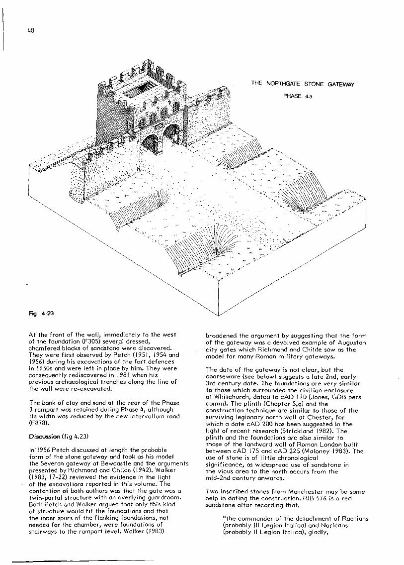
At the front of the wall, immediately to the westof the foundation (F305) several dressed,chamfered blocks of sandstone were discovered.They were first observed by Fetch (1951, 1954 and1956) during his excavations of the fort defencesin 1950s and were left in place by him. They wereconsequently rediscovered in 1981 when hisprevious archaeological trenches along the line ofthe wall were re-excavated.
The bank of clay and sand at the rear of the Phase3 rampart was retained during Phase 4, althoughits width was reduced by the new interval I um road(F878).
Discussion (fig 4.23)
In 1956 Petch discussed at length the probableform of the stone gateway and took as his modelthe Severan gateway at Bewcastle and the argumentspresented by Richmond and Childe (1942). Walker(1983, 17-22) reviewed the evidence in the lightof the excavations reported in this volume. Thecontention of both authors was that the gate was atwin-portal structure with an overlying guardroom.Both Petch and Walker argued that only this kindof structure would fit the foundations and thatthe inner spurs of the flanking foundations, notneeded for the chamber, were foundations ofstairways to the rampart level. Walker (1983)
broadened the argument by suggesting that the formof the gateway was a devolved example of Augustancity gates which Richmond and Childe saw as themodel for many Roman military gateways.
The date of the gateway is not clear, but thecoarseware (see below) suggests a late 2nd, early3rd century date. The foundations are very similarto those which surrounded the civilian enclosureat Whitchurch, dated to cAD 170 (Jones, GDB perscomm). The plinth (Chapter 5,g) and theconstruction technique are similar to those of thesurviving legionary north wall at Chester, forwhich a date cAD 200 has been suggested in thelight of recent research (Strickland 1982). Theplinth and the foundations are also similar tothose of the landward wall of Roman London builtbetween cAD 175 and cAD 225 (Maloney 1983). Theuse of stone is of little chronologicalsignificance, as widespread use of sandstone inthe vicus area to the north occurs from themid-2nd century onwards.
Two inscribed stones from Manchester may be somehelp in dating the construction. RIB 576 is a redsandstone altar recording that,
"the commander of the detachment of Raetians(probably III Legion Italica) and Noricans(probably II Legion Italica), gladly,

willingly, and deservedly fulfilled his vow".
This was found in May 1831 (Bruton 1909, 23) onthe site of the fort. The most reasonable positionfor such an altar would be within the headquartersbuilding, and if we assume that a commander wasunlikely to set up such an altar in a fort whichwas not his own, or, as commander, to be away fromhis garrison, then this altar indirectly records aManchester garrison which had access to redsandstone, and the ability to work it to a highstandard. Birley (1974) thought that the altarcommemorated a legionary detachment that wasprobably sent to Britain in AD 197, to help withthe reconstruction of the province under theEmperor Severus and his sons Caracalla and Geta.Also from Manchester is RIB 581, a fragment from awell-cut monumental inscription found within thefort in 1832 that records:
"the tmperor Antoninus Augustus.and Geta Caesar".
This inscription probably dates from between AD198 and AD 209 when Geta was Caesar. In additionto this, there is a series of Severan buildinginscriptions from the North West (see Chapter 2).
This inscription and where it was discoveredclearly indicate that between AD 198 and AD209major building works had been undertaken withinthe area of the fort, possibly, by virtue of RIB576, by a legionary vexillatio.
The similarity of the wall to dated examples fromelsewhere, the inscriptions, and the relativedating of this phase, clearly suggest that thewall was built in the last quarter of the 2ndcentury or first quarter of the 3rd. If it isaccepted that the monumental inscription actuallyrefers to major work, and so, indirectly, to thewall, then that date range can be narrowed tobetween AD 198 and AD209.
Two pieces of evidence contradict this hypothesis.Firstly, the facing stones of the wall recoveredfrom the Area B Phase 6 deposits (see fig 4.22)and those found by Roeder (1899), Bruton (1909,plate 32), Phelps (1912), and recorded by Dryden(1844) are very small, when compared to those ofthe north wall at Chester that was apparentlybuilt around AD 200 in a very similar stone. Thisdifference in stone working technique may beexplained in several ways: firstly, as it was alegionary base, the construction of the wall atChester was a matter of prestige, and largerstones were used to foster that prestige;secondly, that the greater height of the Chesterwall required larger blocks; thirdly, that thestone working was done by different units, withdifferent working practices; and fourthly, thatthe bedding within the quarry used for theManchester material may have restricted blocksize.
Only one piece of the fort wall at Manchestersurvives above ground level, and this is describedat length by Bruton (1909, 52-6). The foundationsof this wall are, as Bruton pointed out, verysimilar to those discovered by himself, and arealso very similar to those reported here and
elsewhere by Petch (1953, 54-6), Phelps (1912),and Roeder (1899). Bruton excavated beside thiswall fragment, and recorded one layer ofdiagonally laid stones. This report, together withPhelps discovery of a diagonally laid core course,led Simpson (1973) to suggest that as all knowndiagonal coursing was from late 3rd and 4thcentury walls, the wall was of this date. She alsointerpreted some of Bruton's coin finds asindicating that the date of the wall must be afterAD2I7.
The chronological significance of the diagonalcoursing is open to question, in that lateexamples do not disprove the possibility ofearlier ones being found; indeed, Precht (1983,fig 25) has published photographs of diagonalcoursing of a core at Xanten dated to betweencADI06 and cADISO.
More significant is the problem posed by Bruton'sdiscoveries, in which he found a clay zone (1909,section AA) overlying what are equivalent to thisreport's Phase I and 2 ditches and cut by the fortwall. This clay material should, therefore, be thePhase 3 rampart, built when the fort was extended.Dating evidence from this layer should give a clueboth to the date of Phase 3 and to the date afterwhich Phase 4 was begun. Simpson (1973,74)distinguished
"Two turf ramparts not properly distinguishedfrom the third below,... they are certainlyassociated with the succession of ditchesbelow the fort wall foundation".
This clay dump may then represent ramparts of bothPhases 3 and 4. The mixture of finds from it are,given the circumstances of excavation detailed byBruton (1909, 75), of little significance. IfPhelps (1912) could distinguish different layerswhich Bruton coalesced and Simpson differentiated,then, given Bruton's recording techniques, allthat can be said is that from the Phase 3-4 claydump came a complete 2nd century mortarium,(Bruton 1909, 75, 107, plates 66, 68; Simpson1973, 74) and a complete, but broken, 2nd centurysamian bowl, thus broadly confirming the suggesteddate of Phase 3.
Simpson (1973, 75) analysed Bruton's discovery ofa coin of Julia Domna, AD 193-217, made on January5th 1907, and came to the conclusion that it wasfrom the ditches below the wall. This discovery,if correct, would mean that as the coin came fromwhat are known to be Phase 2 ditches, the Phase 3remains are 3rd century and Phase 4, even later.There are, however, reasonable grounds forquestioning whether the coin was from the ditch.Thirteen days after digging in "most inclementweather" (Bruton 1907, 62), Bruton's workmendiscovered the inner eastern edge of the fortwall. Next morning, they returned to find that thetrench had "run in" and in deepening it the coinwas discovered. 'Deepening' in this sense may meaneither re-excavating the run-in trench or takingthe bottom lower. In fact it was probably acombination of both, for "by this time theaccumulated soil from our deep trenches had madework almost impossible" (ibid). This was possiblynot because of its height and the difficulties of

50
spoil disposal, but because spoil was running intothe trenches. Consequently Bruton spent the nextweek in removing it. Given the circumstances ofthe discovery, the supposed location of this coinis very doubtful since it is likely to have beenderived from run-in material. Over the previousweek 0.846in (21.5mm) of rain had fallen, andafter the heavy rainfall of the previous night theground would have been muddy (Bracknell WeatherCentre). Given the problems with the spoil,conditions scarcely aided careful excavation.
Possibly also belonging to this phase is Bruton's(1907) "red sandstone floor", found at Duke Place(see fig 3.2) which was capped with gravel (Bruton1907, plate 36, 76). This almost certainlyrepresents the Phase 4 intervallum road with itsgravel surface. Against this argument is the factthat the Phase 4 intervallum road in Area A is ofa different construction; however that road, F878,is the only intervallum road to contain sandstonefound in the Northgate excavations. Bruton's roadoverlay earlier barrack blocks with stone footingsand was a wholly new construction. On balance itseems simpler, and hence preferable, to assumethat this road was laid down during the rebuildingof the fort in stone. To the west of this road healso discovered a further area of sandstoneflooring (Bruton 1907, 61) which, to judge by itsconstruction technique and depth, was built at thesame time as the road, but whose function remainsobscure.
From the available evidence it seems clear thatthe stone fort wall was built at one point intime. However, Roeder (1899) recorded the innerface of the wall to the east of the gate and hisconventionalised sketch section, (see tig >4.22)which it is difficult to locate precisely, appearsto show a change in walling techniques thatcoincides with the east pier of the Northgate.This discovery seems to argue against the viewthat the stone fort wall was built in oneoperation; however, it is likely that the wall andgate were constructed by different gangs, with themore experienced masons constructing the moredifficult gateway. Evidence of this is the factthat the foundations are identical, and thatRoeder found facing stones on the inner face ofthe wall core where it joins the gate, just as ifthe walling gang had finished their work and,having an excess of facing blocks, placed them inthe core prior to the gateway being built.
The available evidence would suggest then that thefort walls, its roads, gates, and possiblybarracks were rebuilt in the early years of the3rd century and in one operation.
PHASE 4a AREA B (fig 4.18)
5 Bryant
Description
The two ditches (F67 and FI76) which were dugacross the exit road (F42I) during Phase 3b, werelargely backfilled at the beginning of Phase 4(see above), so restoring uninterrupted access tothe Northgate. The Phase 3b inner ditch (F7I9)was recut 1.8m to the north. The Phase 4a recut
(Fl 10) was most clearly represented in Section Cwhere its sump and northern edge survived intact.It had a V shaped profile 2m deep, and an originalwidth of about 5m. The primary filling was a redsandy loam, similar to the primary filling ofFI07, which was cut by Fl 10. As with FI07, thefilling was formed by the natural weathering ofthe sandstone ditch sides. Above this was asecondary filling of clay loam, which containedseveral lines of pebbles and small stones,indicating a gradual accumulation of silt withoccasional short stabilisation horizons.
In section B the ditch (Fl 10) survived as a sump0.1 rn deep, and contained a primary filling ofnatural silt of grey silty loam. In both SectionsB and C, Fl 10 was cut by the Phase 4b ditch F223.
An outer ditch (F737) was observed 7.2m north ofFl 10 on the west side of the exit road (F42I).F737 had a V shaped profile 2m deep by 4.5m wide,and was cut to the north by Fl. It, in turn, cutthe Phase 3a outer ditch (F738) to the south. Thesump of F737 was filled with a qrey silt formed bynatural weathering. This was overlain by astructureless brown sandy loam containing pebbles,similar to the filling of Fl 10, and was probablyformed by gradual, natural accumulation.
Discussion (fig 4.23)
The two Phase 4a ditches (Fl 10 and F737) representa straightforward double ditch system, similar tothat in Phase 3a. Both of the ditches wereprobably slightly larger that any of the precedingditches. This may be a result of the increasingtrend towards larger ditches in the 3rd and 4thcenturies AD. In addition, the fact that both Fl 10and F737 appear to have been allowed to silt upnaturally, suggests that less care was taken tokeep them in good working order than hadpreviously been the case. These ditches are thosereconstructed on the present site.
PHASE 4a AREA C (fig 4.24)
S Bryant
Description
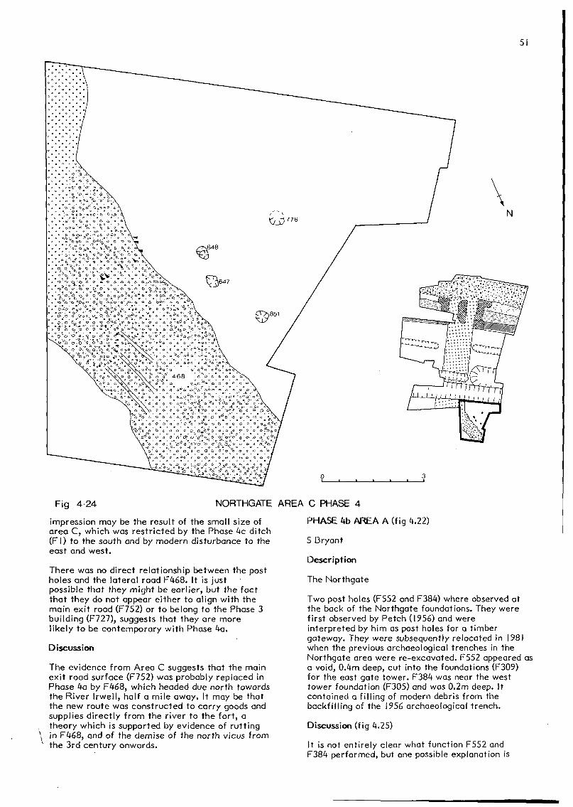
A lateral road (F468) heading due north diagonallyacross Area C was constructed over FI90I, thelevelled remains of building F727. F468 was 3.5mwide, and made up of a single layer of compactedmedium and small cobbles, set in a matrix ofyellow gravel between 0.05m and 0.15m deep.Several wheel ruts were apparent in the surface ofF468. At the junction of F468 and the main exitroad (F752) the soft filling of the drainage ditch(F868) had also caused some subsidence.
Four post holes were observed to the south of thelateral road (F468). They were all cut into thefilling of the Phase 2c industrial feature. F647was 0.35m deep and contained a filling ofsandyloam and was cut by a single post replacementof the same dimensions and with a similar filling.F648 was 0.4m deep and contained a filling of loamwith several sandstone blocks, as did F85I andF776. The four post holes did not appear to formpart of any regular structure, although this
51
Fig 4-24 NORTHGATE AREA C PHASE 4
impression may be the result of the small size ofarea C, which was restricted by the Phase 4c ditch(Fl) to the south and by modern disturbance to theeast and west.
There was no direct relationship between the postholes and the lateral road F468. It is justpossible that they might be earlier, but the factthat they do not appear either to align with themain exit road (F752) or to belong to the Phase 3building (F727), suggests that they are morelikely to be contemporary with Phase 4a.
Discussion
The evidence from Area C suggests that the mainexit road surface (F752) was probably replaced inPhase 4a by F468, which headed due north towardsthe River Irwell, half a mile away. It may be thatthe new route was constructed to carry goods andsupplies directly from the river to the fort, atheory which is supported by evidence of ruttingin F468, and of the demise of the north vicus fromthe 3rd century onwards.
PHASE 4b AREA A (fig 4.22)
S Bryant
Description
The Northgate
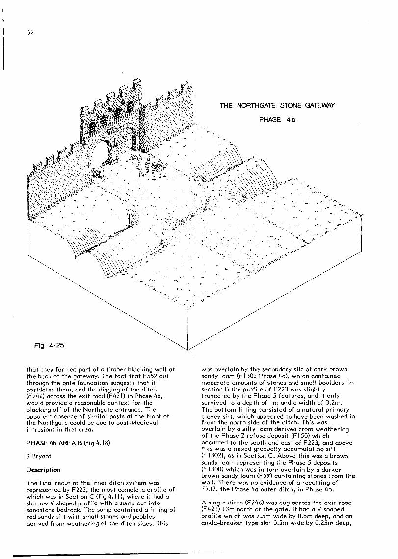
Two post holes (F552 and F384) where observed atthe back of the Northgate foundations. They werefirst observed by Petch (1956) and wereinterpreted by him as post holes for a timbergateway. They were subsequently relocated in 1981when the previous archaeological trenches in theNorthgate area were re-excavated. F552 appeared asa void, 0.4m deep, cut into the foundations (F309)for the east gate tower. F384 was near the westtower foundation (F305) and was 0.2m deep. Itcontained a filling of modern debris from thebackfilling of the 1956 archaeological trench.
Discussion (fig 4.25)
It is not entirely clear what function F552 andF384 performed, but one possible explanation is
52
THE NORTHGATE STONE GATEWAY
PHASE 4b
Fig 4-25
that they formed part of a timber blocking wall atthe back of the gateway. The fact that F552 cutthrough the gate foundation suggests that itpostdates them, and the digging of the ditch(F246) across the exit road (F42I) in Phase 4b,would provide a reasonable context for theblocking off of the Northgate entrance. Theapparent absence of similar posts at the front ofthe Northgate could be due to post-Medievalintrusions in that area.
PHASE 4b AREA B (fig 4.18)
S Bryant
Description
The final recut of the inner ditch system wasrepresented by F223, the most complete profile ofwhich was in Section C (fig 4.1 I), where it had ashallow V shaped profile with a sump cut intosandstone bedrock. The sump contained a filling ofred sandy silt with small stones and pebblesderived from weathering of the ditch sides. This
was overlain by the secondary silt of dark brownsandy loam (FI302 Phase 4c), which containedmoderate amounts of stones and small boulders. Insection B the profile of F223 was slightlytruncated by the Phase 5 features, and it onlysurvived to a depth of Im and a width of 3.2m.The bottom filling consisted of a natural primaryclayey silt, which appeared to have been washed infrom the north side of the ditch. This wasoverlain by a silty loam derived from weatheringof the Phase 2 refuse deposit (FI50) whichoccurred to the south and east of F223, and abovethis was a mixed gradually accumulating silt(FI302), as in Section C. Above this was a brownsandy loam representing the Phase 5 deposits(FI300) which was in turn overlain by a darkerbrown sandy loam (F59) containing stones from thewall. There was no evidence of a recutting ofF737, the Phase 4a outer ditch, in Phase 4b.
A single ditch (F246) was dug across the exit road(F42I) 13m north of the gate. It had a V shapedprofile which was 2.5m wide by 0.8m deep, and anankle-breaker type slot 0.5m wide by 0.25m deep,

53
in the bottom. The bottom filling of F246consisted of a silty clay derived from the naturalweathering of the ditch sides. This was overlainby a structureless brown sandy loam, similar tothe secondary filling of F223, which probablyrepresents a post-Roman soil accumulation. Therewas no evidence of a deliberate backfilling ofF246. The complete eastern end of F246 could notbe located as it terminated in an area unavailablefor excavation. However, part of the terminal endto F246 was located west of the exit road (F42I)and the fact that it did not appear in Section Csuggests that F246 was dug for the same reason asF67 and F176, just to prevent access to theNorthgate.
Discussion (fig 4.25)
The gradual accumulating secondary filling of F246suggests that the road (F42I) was not used afterthe digging of F246. F42I, therefore, almostcertainly postdates the construction of the Phase4a Northgate and is possibly contemporary with thepost holes (F552 and F384) at the back of the
gate. As with the Phase 3b ditch (F67) therelativly small size of F246 indicates that it wasprobably not designed as a purely defensiveobstacle, and that its main purpose was to preventaccess to the Northgate.
PHASE 4c AREA B (fig 4.18)
5 Bryant
Description
The Phase 4a outer ditch (F737) was cut to thenorth by Fl which formed the latest ditch in thesequence in front of the Northgate. This was a Vprofile ditch 4.2m wide by 1.8m deep, andcontained a primary filling of silt and secondaryfilling (FI302) of loam, similar to the filling ofF737. Fl cut through the exit road (F42I) 4m tothe north of F246, and formed a much moreformidable defensive obstacle than F246; as suchit probably means that the Northgate had beenfinally closed.
THE NORTHGATE STONE GATEWAY
PHASE 4c
Fig 4-26

54
Discussion (fig 4.26)
The virtual absence of 3rd and 4th century findsfrom the large volume of ditch filling excavatedfrom Fl, suggests that it was probably kept openduring the 4th century. This contrasts with thePhase 4c filling, FI302, of ditch F223, whichproduced all of the late 4th century pottery foundduring the excavations and two late 4th centurycoins. Therefore F223 was probably allowed to siltup during the 4th century, leaving Fl as the onlydefensive ditch during Phase 4c.
PHASE 5 AF£A B (fig 4.27)
S Bryant
Description
Four sunken features were encountered north of thePhase 4a stone wall. F547 was cut into thesecondary filling of F223; it was 4m long by 3mwide and Im deep, with steeply sloping sides.Nineteen possible stake holes were cut into thenatural sand subsoil to a depth of 0.1 m, andcontained a brown silty loam fill. More of thesemay have been present around the rest of thefeature, as it was not possible to identify themin the filling of F223.
The second sunken feature, F229 (Section E, fig4.21) was cut through the exit road (F42I), Phase3b ditch (FI76) and the Phase 2 ditch (F249). Alayer of compacted gravel, 229a, lined the bottomof the feature, and was overlain by two separatedeposits of silt 229b and 229c. A deposit ofgravel 229d, possibly created by erosion from thesides of the feature, was observed in Section E.Another layer of silt 229e occurred in theinfilling of deposit F59. An irregular feature(F23I) was found with F229 at its south eastcorner, but the relationship between the two isunclear; a number of possible stake holes wereobserved surrounding F229, which were cut into thePhase 2 refuse deposit, FI50, filling the Phase 2ditch, F249.
The third sunken feature, F290, was 3.2m long by2m wide and 0.6m deep. As with F229, it was cutthrough the exit road F42I and the Phase 2 ditchF249, and also had possible stake holes around itsperiphery which were similar in nature to thosefrom F547 and F229.
The fourth sunken feature (F804) was larger thanthe other three, measuring 6.4m by 2.5m. It was0.7m deep on the north side, where it cut into thefilling of the Phase 3a ditch (F738) and O.lm deepon the south. It, too, was surrounded by possiblestake holes which cut into the ditch filling ofF738 and F223 to the south. F804 contained a layerof small stones set in a matrix of compacted siltyloam.
To the south of F804 was a spread of red sandstoneset in green silty loam (FI303) which containedanimal bone and charcoal; it sealed the secondaryfilling of the Phase 4 inner ditch (F223). Northof F804 was a layer of semi-angular cobble set ina sandy loam (FI300), which sealed the secondaryfilling of the Phase 4a outer ditch (F737). This
layer also occurred to the east but did notcontinue towards F547. Associated with this layerwere two separate groups of possible stake holes.The first group lay in an apparently haphazardcluster between F804 and F290. The second groupwas located north of the cobble and clay layer, inthe filling of the Phase 4c ditch (Fl). Furtherpossible stake holes may have existed along thesouthern edge of Fl, but it was not possible toexcavate further in this direction because ofmodern intrusions.
Discussion
V Tanner
The sunken features were cut into the secondaryfilling of ditch F223, which contained late 4thcentury pottery, and so are 4th century or later.It also seems probable that no wall demolitionoccurred prior to their construction. However, asthey neither contained, nor were cut or sealed by,any features containing datable artefacts, theycan not be assigned a more precise date.
By virtue of their dimensions and dating, onepossible interpretation of these features is thatthey are the remains of Anglo-Saxon sunken flooredhuts, known as grubenhauser, and it is possiblethat the deposit of a compacted silty loam foundin F804 is the occupation floor of such abuilding.
The sizes of sunken floored buildings vary from1.8m by 1.5m to 9.1 m by 5.1 m (Rahtz 1981,75) andthose from the site would fit comfortably withinthis range. They are frequently found to haveassociated settings for posts or stakes to supporttheir roofs and walls. The most common type of hutis the two post type, though some have a series ofpost holes numbering six or more (Rahtz 1981,81).Stake holes, where present, are usually foundwithin the sunken area (Bell 1977, 202). The rangeof possible functions assigned to these buildingsis summarised in Rahtz (op cit, 76):living-houses, barns, or specialist craft hutsbeing among the suggested functions. Against theinterpretation of the Phase 5 features assunken-floored buildings are a number of facts.The first is geographical; sunken-featuredbuildings are rare north and west of a line drawnbetween the rivers Tees and Exe (Rahtz 1981, fig2.1). The second is structural; sometimes, ashere, post holes are absent, for example at Ezinge(van Giffen 1936, Beilage 2, Abb 2), but inBritain this is extremely uncommon. It is alsounusual to encounter stake holes outside the area,and the fact that those recovered at Manchestermight represent root holes can not be totallydiscounted. Indeed, such a theory has beenconsidered recently by Watkins (1983), where theroots of certain plant species have been found toproduce holes identical in shape to possible stakeholes.
Thirdly, the absence of artefacts is also rare;however, the layer containing organic materials(FI303) to the south of F804 could be a middendeposit resulting from the use of this or any ofthe other sunken features. Finally, whilst

5m
Fig 4-27 NORTHGATE AREA B PHASE 5

56
sunken-featured buildings are occasionally theonly type of structure in a settlement, as forexample at Cassington (Arthur and Jope 1962), theyare often found with other house types and tracesof occupation.
The positioning of these features on the line ofthe exit road leaving the Roman fort is a pointworth commenting on, in view of the presence ofsimilar remains along a road running east-west atthe Saxon Shore fort of Portchester (Cunliffe1976, 301). These structures were interpreted ashuts of late 4th/early 5th century Germanicmercenaries living in the lee of the fort. Therewere, however, more extensive remains ofsettlement in the form of structural features andartefacts, both in and outside the fort,throughout the immediate post-Roman and Saxonphases. The blocked Phase 4 roadway and thewell-draining backfilled ditches provided, at theend of the Roman period, a reasonably dry sitewith a slight hollow of soft ground runningparallel to the wall. This hollow was still to beseen in the 18th century (Whitaker 1771). It isclear that, given their size and shape, suchsunken features could, despite latter levellingand intrusions, have been found in Areas A and C.That they were not, clearly shows that they werelimited to a single line. As wall debris ranacross these features it is probable that the wallstill remained to a substantial height when theywere in use and it would seem reasonable to assumethat it afforded some protection against theprevailing south-west winds.
In the light of the discussion above, theinterpretation of these features assunken-featured buildings cannot be definitelyproved one way or the other. It is possible thatthey represent remnants of a brief stay by a smallgroup of people at this spot, or that theyrepresent non-domestic features relating toactivity of a completely different nature; theevidence presently available is insufficient tosupport either theory.
PHASE 6 AREA B (fig 4.28)
J Walker
Description
Overlying the Phase 5 deposits and the initialfilling of F547, F229, F23I, F290, F804, was alayer (F59) of red sandstone fragments, pieces ofyellow mortar and some glacial pebble (Section C).Contained within this layer were blocks of cut redsandstone.
Discussion
The cut red sandstone blocks were almost certainlythe remains of the collapsed facing wall of thePhase 4 fort. The yellow mortar and irregularsandstone and pebble fragments were also possiblyderived from the facing and core of the fort wall.The absence of voussoirs, coping stones and otherarchitectural elements from the gate and wall, andthe presence of mortar fragments from thisdeposit, may indicate that the wall was robbed ofmuch of its stonework. Stones derived from the
wall occur, however, sporadically throughout thegradually accumulating erosion material of laterphases (Section E fig 4.21) and it is clear thatsome, at least, of these fallen deposits resultfrom the collapse and erosion of the wall. Theabsence of mortar in these later phases indicatesthat these initial deposits were different to thelater material formed by natural processes.
If the hypothesis of deliberate robbing isaccepted, then it is difficult to imagine ahistorical context for the activity as, by virtueof the stratigraphy, the event took place afterthe construction of the possible grubenhauser andthe demise of the fort, and therefore in the 5thcentury or later and yet prior to the Phase 7activity thought to be associated with a medievalpark. Therefore this activity took place in what,for the North-West, were the Dark Ages.
Although examples of Dark Age stoneworking areknown from places such as Wroxeter, in the North-West the earliest dates are associated with thebuilding of stone churches which commenced aroundthe 8th or 9th century. Collapsed facing stoneswere also seen by Bruton (1909), Roeder (1899),Phelps (1913) and Petch (1956) along the north andeastern wall and similar blocks in situ arerecorded by Dryden (1844). Bruton found two early4th century coins (1909, nos 13 and 14) which mayhave come from this deposit, and Petch (1956, no5) a late Roman mortarium. These finds confirm thesuggested late or post-Roman date. It may be,however, that the large patches of facing stonesand mortar represent the deliberate toppling ofthe defences, although in this case one would haveexpected architectural fragments to be found. Thistoppling may be associated with the creation ofthe Anglo-Saxon burh (D Hill, pers comm).
The Anglo-Saxon Burh
The Anglo-Saxon Chronicle records that in AD 919King Edward ordered an army of Mercians to occupyManchester, in Northumbria, and to repair and manit (Morris 1983, 15; Harland 1861, 13). The word"gebetan", used in the Manchester entry, is quitedifferent from that usually used elsewhere in theAnglo-Saxon Chronicle to denote the building of anew burh. Its use may be evidence that at oraround Manchester, reconstruction work upon apre-existing defensive structure was taking place.
The reconstruction of the burh appears to havebeen part of a concerted plan by Edward to createa series of forts demarking the northernboundaries of his territory. In AD 923, when thefinal fort at Bakewell was established, peace wasachieved when Edward received the submission ofthe northern kings. It is interesting to note thatthe repair of the burh indicates that it probablyexisted prior to AD 919, as a number of traditionssurvive to the effect that Dark Age Manchester wasvariously occupied by Queen Ethelburga, wife ofKing Ine of Wessex sometime around AD 686 (Harland1861, I 1-12); the Danes (Morris 1983, 15); and thegiant Tarquin, killed by Sir Lancelot (Stukeley1776; Horsley 1732).
At Rhuddlan, King Edward built a new burh that mayhave enclosed 72 acres (29.1 ha). It was defended

5m
Fig 4-28 NORTHGATE AREA B PHASES 6 AND 7

58
by a 13m wide bank, in front of which was a ditch17m wide and up to 3m deep (Hanley 1981). Notraces of such large ditches have been foundimmediately outside the fort at Manchester,neither is there room for them, (see fig 4.7).
Whitaker (1771, 28-30, 52-3, 272-3) recorded thepresence of large ditches, to the east, north andwest of the fort, apparently running down to theriver. The confused nature of his text makes itimpossible to locate them, but it is just possiblethat they may represent a ditch similar to that atRhuddlan.
There is, then, no clear evidence for the re-fortification of the fort, and the hypothesis thatEdward was referring to the area around thecathedral seems quite attractive. However, theChronicle refers to three distinct actions to beundertaken by the "army" of the "people ofMercia", namely: to occupy Manchester; to repairthe existing defences (either at the fort oraround the cathedral area); and to man theresulting structure. It is always possible thatthe occupation took place but, as the Chronicle isrecording an order, not an event, that the repairand manning did not. All that can be said, at thisstage, is that the Phase 6 deposits probablyresult from the robbing of the wall for stone fora structure, possibly the burh, elsewhere.
Whitaker (1771) recorded a tradition that stonesfrom the fort were used in the building of thecathedral and bridges in medieval Manchester.There seems to be no reason to doubt this, but ifthe cause of the various deposits outlined hereand below is accepted, then Phase 5, the onlystone-robbing phase, is unlikely to be as late asManchester's medieval bridges, as insufficienttime would be available for the formation of thePhase 7 and 8 deposits. Whitaker's recordpreserves the obvious fact that the deserted fortrepresented the best source of stone in the areabetween the 4th and 18th centuries.
PHASE 7 AREA B (fig 4.28)
J Walker
Description
In 1978 Professor Jones discovered a series ofpost holes cut into layer 59, Phase 4. Some ofthese post holes contained voids: however, themajority of them, all of which were U shaped inprofile, were filled with a matrix very similar tothat of Layer 59. During this phase a furtheraccumulation of derived material occurred in theupper filling of the ditches (fig 4.7 and fig4.21).
No post holes belonging to this phase were foundin Areas A and C but this is unlikely, given theirdepth, to have been due solely to later levelling.It seems likely, therefore, that they onlyoriginally existed in Area B.
Discussion
The plan of the post holes would seem to indicatethat they formed part of a rectanaular structure
approximately IOm by 5m. The size of thisbuilding, and its construction techniques, aretypical of the remains of Medieval and Anglo Saxonrural structures, although Anglo Saxon gatewayswhich always appear to be at the rear of therampart front, can produce similar patterns ofpost holes (Gould 1968-9).
There are a number of factors that make itunlikely that the post holes represent an Anglo-Saxon refurbishment of the gate, namely thedistance of the post holes from the gateway, thepresumed condition of the demolished gate and thefact that projecting gateways are a later medievalphenomenon. Although it has proved impossible toaccurately date this phase of the site, it wouldseem reasonable to suppose that the pattern ofpost holes, recovered by Professor Jones,represents the continuation of rural settlementoccurring in Phase 5.
Camden recorded, about 1600, that the fort stoodwithin the park of the Earl of Derby known asAldport. Together with Over Aldport, the park,first recorded in 1282 (Roeder 1899), included alodge fronting onto Deansgate (Palmer 1822). In1322 (Wright- Procter 1874) the Nether Aldportarea consisted of 30 acres (12.1 ha) of heath, 20acres (8.1 ha) of pasture, 2 acres (O.Sha) ofmeadow and presumably 43 acres (I7.4ha) ofwoodland. Roeder (1899) comments on the fact thatthe apparent bounds of Aldport correspond to thearea of Roman settlement. Its northern boundaryappears to have been formed by Quay Street whichalso marked Whitaker's limit of Roman material(see fig I.I) and the southern boundary of themanor of Manchester (Harland 1861). Pre-Hanoverianhouses also occurred at various places alongDeansgate that were known as Aldport town (Cassonand Berry map of 1750; Whitaker 1771), but theseare, traditionally, late expansions fromManchester (Roeder 1899). It seems most likelythat the post hole building was probablyassociated with the park, and may have been asmall agricultural building. The significance ofthe name of Aldport, meaning 'old town' or 'oldmarket', remains unclear as there is, as yet, noclear archaeological evidence for extensiveoccupation or use of the area in the periodbetween the end of the fort and 1322.
PHASE 8 AREA B (fig 4.7)
J Walker
Description
The upper fills of the ditches in Area B consistedof a silty brown loam that contained occasionalstone fragments.
Discussion
A soil survey by Mr J McPeake indicated that thisdeposit was similar to the majority of the upperditch fills, and it would seem to represent thegradual accumulation of erosion deposits. The lackof any inherent zonation in this layer mayindicate that the area had been ploughed at somepoint. These soils probably accumulated when thearea was agricultural land.

59
PHASE 9 AREAS A, B & C (fig 4.7)
J Walker
Description
The whole site was covered by a mixture of brownand black loam layers, containing 19th century andlater finds as well as the remains of pipes,drains and other services.
Discussion
It is clear from the sections that these moderndeposits, in places, removed and destroyed anumber of layers representing the later phases ofthe site.
In Area A, Phase 4 deposits were immediatelyoverlain and cut away by these deposits, and thesame is true of Area C. Only in Area B were theremains of later phases found, so that it is notclearly known how much activity took place inAreas A and C in later phases. It is possible thatvery little activity occurred in these phases onthe site as a whole for the following reason.Regardless of disturbance, pottery is a relativelyindestructable item; therefore, if Hanoverianworks had disturbed later levels in Areas A and C,the pottery from them should have survived in theHanoverian and later levels. The dearth of laterRoman pottery from the site clearly suggests thatoccupation was relatively slight.