north kenai spur, mp 22-29.7dot.alaska.gov/creg/design/highways/specs/proj_specs_a… · web...
TRANSCRIPT

PART 4
STANDARD MODIFICATIONS
AND SPECIAL PROVISIONS
to the STATE OF ALASKA
SPECIFICATIONSFOR
HIGHWAY CONSTRUCTION
2004 STANDARD SPECIFICATIONS
NORTH KENAI SPUR ROAD, MP 22-29.7PROJECT /56567

SPECIAL NOTICE TO BIDDERS
The Department hereby notifies bidders that information to assist in preparing bids is available at 4111 Aviation Avenue for the following:
1. These items are available upon request in the Anchorage Department of Transportation and Public Facilities Building Plans Room:
a. Quantity Computations, Cross Sections, and Test Hole Logs
b. State of Alaska Department of Transportation and Public Facilities publication, Alaska Storm Water Pollution Prevention Plan Guide.
c. Department of Transportation and Public Facilities - Sign Face Fabrication Requirements
d. Standard Specifications for Highway Construction 2004. ($25.00)
e. Alaska Test Methods Manual (Lab & Field), 2004 Edition. ($25.00)
2. Utility agreements pertaining to the disposition of utility facilities on this project are available for review at the office of the Utilities Engineer, (907) 269-0686.
3. The Department has an approved environmental document addressing concerns and environmental commitments and it is available for review in the office of the Regional Environmental Coordinator, (907) 269-0534.
4. The Materials Certification List (MCL) has been included in Appendix E. This list is provided for the Contractor to determine which materials will require submittal to the project Engineer for certification of compliance. The MCL also provides the Project Engineer with the appropriate approving authority.
5. Refer to subsection 105-1.07 for projects being constructed concurrently with this project.
6. The Laborers’ Mechanics’ Minimum rate of Pay effective September 1, 2004 Issue 9, contains information on remote sites and per diem. The department of Labor has issued WHPL #197, which further clarifies this requirement. See pay item 640(2).
NORTH KENAI SPUR ROAD, MP 22-29.7PROJECT /56567

- 1 -
SECTION 101
DEFINITIONS AND TERMS
Special Provisions
101-1.03 DEFINITIONS. Add the following definition:
NON-FROST SUSCEPTIBLE MATERIAL. Material that contains 6 percent or less passing the No. 200 screen as determined by sieve analysis performed with WAQTC FOP for AASHTO T 27/T 11on minus 3 inch material. (11/29/01) R1M98
NORTH KENAI SPUR ROAD, MP 22-29.7PROJECT /56567

- 2 -
SECTION 102
BIDDING REQUIREMENTS AND CONDITIONS
Standard Modification
102-1.05 PREPARATION OF BID. Modify the second sentence in the third paragraph, after: “If a bidder is a corporation, the bid must be signed by a corporate officer,” add: or agent. E18(6/30/04)
NORTH KENAI SPUR ROAD, MP 22-29.7PROJECT /56567

- 3 -
SECTION 105
CONTROL OF WORK
Special Provisions
105-1.06 UTILITIES. Add the following: The Contractor shall request locates from the utilities having facilities in the area. The Contractor shall use the locate Call Center for the following utilities:
Locate Call Center 800-478-3121Who will notify the following:
Alaska Communications Systems Inc. (ACS)Enstar Natural GasHomer Electric Assoc.Marathon Oil Company Tesoro Alaska Pipeline Unocal
The Contractor is cautioned that the Locate Call Center does not contact the agencies and utilities listed below for underground locates. The Contractor shall call ***deleted*** these agencies directly:
DOT/PF Maintenance and Operations (highway lighting)...........................(907) 262-2199Kenai Peninsula Borough (highway lighting and flashing speed limit signs)(907) 262-4427McGahan Utilities (Nikiski water system)...................................................(907) 776-6559Ocean Beauty Seafoods Inc. (Nikiski sewer crossing).................................(907) 776-8174
***deleted*** Clear and grub those areas designated below for relocation. Slope stake highway and pathway cuts and fills in utility relocation areas prior to the start of utility and pipeline appurtenance relocations, so that the extents of proposed relocations can be verified in the field and adjusted if necessary.
Some of the existing utilities and pipeline appurtenances are scheduled for relocation as addressed in the following sections. Existing utilities, pipelines, and appurtenances that are not specifically listed below for relocation or abandonment, shall be considered as Contractor work-arounds for bidding purposes.
NORTH KENAI SPUR ROAD, MP 22-29.7PROJECT /56567

- 4 -
ALASKA COMMUNICATIONS SYSTEMS INC. (ACS)
***deleted***
ACS or an ACS contractor will complete the telecommunications facility relocations and abandonments, including the following:
***deleted***
Sheet F2 - 400 lineal feet of existing 25 pair underground cable will be relocated from Sta. 573+00 Right to Sta. 577+00 Right, and a new pedestal will be added at Sta 577+00+/- Right to accommodate highway sight line excavation. Allow 3 calendar days for this work.
Sheet F10 – 150 lineal feet of existing 200 pair underground cable will be relocated from Sta. 664+70 Left to Sta. 664+70 Right to accommodate highway ditch excavation. Allow 5 calendar days for this work
Sheet F12 – 150 lineal feet of existing 25 pair underground cable will be relocated from Sta. 689+25 Left to Sta. 689+25 Right to accommodate highway grade reduction and ditch excavation. Allow 4 calendar days for this work
Sheet F13 – 150 lineal feet of existing 100 pair underground cable will be relocated from Sta. 707+90 Left to Sta. 707+90 Right to accommodate pathway excavation. Allow 4 calendar days for this work
Sheets F22 and F23 - 320 lineal feet of existing 25 pair underground cable will be abandoned from Sta. 815+50 Left to Sta. 818+70 Left to accommodate highway grade reduction and pathway excavation. Allow 1 calendar day for the abandonment work
Sheet F24 - 450 lineal feet of existing 150 pair underground cable will be relocated from Sta. 832+00 Left to Sta. 836+50 Left, and new pedestals will be added at Sta. 832+00 Left and Sta. 836+50 Left, to accommodate pathway excavation. Allow 3 calendar days for this work
Sheet F26 – 160 lineal feet of existing 300 pair underground cable will be relocated from Sta. 865+70 Left to Sta. 865+90 Right, to accommodate highway ditch and pathway excavation. Allow 5 calendar days for this work
Sheet F28 - 300 feet of existing 150 pair underground cable will be relocated from Sta. 884+50 Left to Sta. 887+50 Left, and a new pedestal will be added at Sta.884+50- Left, to accommodate Rounds Road approach excavation. Allow 3 calendar days for this work
Sheets F28 through F30 - 2,135 lineal feet of existing 25 pair underground cable will be abandoned from Sta. 884+90 Left to Sta. 906+25 Left, to accommodate pathway excavation. Allow 1 calendar day for the abandonment work.
NORTH KENAI SPUR ROAD, MP 22-29.7PROJECT /56567

- 5 -
Sheet F29 - 260 lineal feet of existing 150 pair underground cable will be relocated from Sta. 898+50 Left to Sta. 901+10 Left, and a new pedestal will be added at Sta. 898+50 Left, to accommodate pathway excavation. Allow 3 calendar days for this work
Sheet F32 - 170 lineal feet of existing 25 pair underground cable will be relocated from Sta. 933+80 Left to Sta. 934+50 Right to accommodate highway grade reduction. Allow 4 calendar days for this work
Sheet F34 - 150 lineal feet of existing 300 pair underground cable will be relocated from Sta. 959+20 Left to Sta. 959+20 Right, and 250 lineal feet of new 25 pair underground cable will be added from Sta. 959+20 Right to Sta. 961+80 Right, to accommodate highway grade reduction. Allow 4 calendar days for this work
Sheet F34 - 120 lineal feet of new underground service cable will be added from Sta. 961+10 Left to an existing home at Sta. 961+90 Left, to accommodate highway grade reduction. Allow 2 calendar days for this work
Sheets F34 and F35 - 1,350 lineal feet of existing 25 pair underground cable will be abandoned from Sta. 951+70 Left to Sta. 965+20 Left, and 210 lineal feet of existing 25 pair underground cable will be abandoned from Sta. 961+60 Right to Sta. 962+50 Left, to accommodate highway grade reduction. Allow 1 calendar day for the abandonment work
***deleted***
***deleted***
DEPARTMENT OF TRANSPORTATION AND PUBLIC FACILITIES (DOT/PF)
***deleted***
ENSTAR NATURAL GAS COMPANY
Enstar or an Enstar contractor will complete the natural gas facility relocations and a distribution system extension, including the following:
Sheet F2 - 360 lineal feet of existing 4” natural gas transmission main from Sta. 574+00 to Sta. 577+60 right will be relocated to accommodate highway sight line excavation. The 4” natural gas transmission main must be relocated while an existing natural gas fired power plant, which is fueled by the pipeline, is shut down. The power plant operates intermittently, and the shutdown schedule of the plant cannot be determined more than approximately one week in advance. The shutdown will be coordinated through the Engineer.
NORTH KENAI SPUR ROAD, MP 22-29.7PROJECT /56567

- 6 -
Before relocation of the transmission main, clear and grub the right-of-way as required for relocation, to the satisfaction of the Engineer. Schedule sight line excavation shown on Sheet E1 to occur after relocation of the 4” natural gas transmission main is completed. Allow 7 calendar days for this work
Sheets F7 through F9 - 2,605 lineal feet of new 3” natural gas distribution line will be installed from Sta. 629+75 Right to Sta.655+80 Right, and 220 lineal feet of new 3” natural gas distribution line crossing will be installed from Sta. 639+00 Right to Sta. 637+90 Left. Allow 7 calendar days for this work
Sheets F12 and F13 –225 lineal feet of existing 2” natural gas distribution line Sta 696+75+/- Left to Sta 699+00+/- Left will be relocated to accommodate new culvert installation. Allow 3 calendar days for this work
Sheet F23 - 150 lineal feet of existing 2” natural gas distribution line crossing at Sta. 818+20 will be relocated to accommodate highway grade reduction. Allow 3 calendar days for this work
Sheets F23 and F24 - 1250 lineal feet of existing 4” natural gas distribution line from Sta. 826+00 Right to Sta. 838+50 Right will be relocated to accommodate highway grade reduction. The relocated line will be increased to 6” diameter. An existing 1” natural gas distribution line will be connected to the new 6” natural gas distribution line at Sta. 827+50 Right. Allow 4 calendar days for this work
Sheets F28 and F29 - 650 lineal feet of existing 4” natural gas distribution line will be relocated from Sta. 885+50 Right to Sta. 892+00 Right to accommodate highway grade reduction. The relocated line will be increased to 6” diameter. An existing 5/8” natural gas service line will be connected to the new 6” natural gas distribution line at Sta 889+50+/- Right. Allow 3 calendar days for this work
Sheets F29 and F30 - 400 lineal feet of existing 4” natural gas distribution line will be lowered from Sta. 899+50 Right to Sta. 903+50 Right to accommodate highway turn lane construction. 140 lineal feet of new 5/8” natural gas service line crossing will be installed and connected to the new 6” natural gas distribution line at Sta. 900+50 Right. Allow 3 calendar days for this work
Sheets F32 and F33 - 1100 lineal feet of existing 4” natural gas distribution line will be relocated from Sta. 929+00 Right to Sta. 940+00 Right to accommodate highway grade reduction. The relocated line will be increased to 6” diameter. An existing 5/8” natural gas service line will be connected to the new 6” natural gas distribution line at Sta. 932+00 Right. 150 lineal feet of new 2” natural gas distribution line crossing will be installed and connected to the new 6” natural gas distribution line at Sta. 936+50 Right. Allow 4 calendar days for this work
Sheet F34 - 600 lineal feet of existing 2” natural gas distribution line will be relocated from Sta. 955+50 Right to Sta. 961+50 Right to accommodate highway grade reduction. The relocated line will be increased to 4” diameter. Allow 3 calendar days for this work
NORTH KENAI SPUR ROAD, MP 22-29.7PROJECT /56567

- 7 -
When working near natural gas pipes, adhere to ENSTAR’s “Safety Requirements for Excavation Adjacent to Natural Gas Pipelines.” Attached as Appendix F.
Flexible carsonite markers for the Enstar facilities will be left in place and shall be protected during construction. Where markers are in direct conflict with highway construction, such as in cut or fill areas, markers shall be carefully removed ***deleted*** and delivered to Enstar.
HOMER ELECTRIC ASSOCIATION (HEA)
HEA or an HEA contractor will complete the electrical facility relocations, including the following:
Sheet F19 – An existing power pole with down-guy and anchor at Sta. 779+75 right will be relocated to avoid conflict with Haliburton Drive approach improvements. Allow 3 calendar days for this work
Sheet F20 - A new power pole, down-guy, and anchor will be added at Sta. 791+80 Left, and an existing down-guy and anchor at Sta. 791+80 Left will be removed to avoid conflict with the proposed pathway. Allow 3 calendar days for the installation of the new power pole, down-guy, and anchor, and the removal of the existing down-guy and anchor.
Sheet F22 - A new power pole, down-guy, and anchor will be added at Sta. 812+20+/- Left, and an existing down-guy and anchor at Sta. 812+20 Left will be removed to avoid conflict with the proposed pathway. Allow 3 calendar days for the installation of the new power pole, down-guy, and anchor, and the removal of the existing down-guy and anchor.
Sheet F26 - A new power pole, down-guy, and anchor will be added at Sta. 865+70 Left, and an existing down-guy and anchor at Sta. 865+70 Left will be removed to avoid conflict with the proposed pathway. Allow 3 calendar days for the installation of the new power pole, down-guy, and anchor, and the removal of the existing down-guy and anchor.
Sheet F27 - A new power pole, down-guy, and anchor will be added at Sta. 877+75 Left, and an existing down-guy and anchor at Sta. 877+75 Left will be removed to avoid conflict with the proposed pathway. Allow 3 calendar days for the installation of the new power pole, down-guy, and anchor, and the removal of the existing down-guy and anchor.
Sheet F28 - An existing power pole at Sta. 884+85 Left will be replaced with two new poles to avoid conflict with Rounds Road approach improvements. Allow 3 calendar days for the installation of the two new power poles, and the removal of the existing power pole.
NORTH KENAI SPUR ROAD, MP 22-29.7PROJECT /56567

- 8 -
Three new load centers for highway intersection lighting will be installed, HEA or an HEA contractor, will supply electrical service to these facilities once they are inspected and tagged. Notification will be provided to HEA through the Engineer once the facilities are tagged and the service will be scheduled for hookup.
KENAI PENINSULA BOROUGH (KPB)
***deleted***
MARATHON OIL COMPANY
***deleted***
Marathon natural gas pipelines are shown on plan views on the Sheets F1 through F13 with the designation “OIL”.
Cathodic protection test stations at Sta 587+00***deleted*** Right, and Sta 592+00***deleted*** Right, will be relocated or removed and replaced by Unocal under agreement with Marathon.
Notify Marathon and the Engineer at least 2 working days prior to any excavation within 5 feet of Marathon facilities. Unocal, under agreement with Marathon, will provide a pipeline safety inspection of excavations adjacent to Marathon facilities.
Flexible carsonite markers for the 20” and 16" Marathon pipelines will be left in place and shall be protected during construction. Where markers are in direct conflict with highway construction, such as in cut or fill areas, markers shall be carefully removed ***deleted*** and delivered to Unocal, who will reset the markers under agreement with Marathon.
McGAHAN UTILITIES
***deleted***
OCEAN BEAUTY SEAFOODS INC.
***deleted***
NORTH KENAI SPUR ROAD, MP 22-29.7PROJECT /56567

- 9 -
UNOCAL
***deleted***
Unocal natural gas pipelines are shown on the plan views on Sheets F1 through F13 with the designation “OIL”.
Unocal or a Unocal contractor will complete various natural gas pipeline appurtenance relocations including the following:
Sheet F1 - Casing vents at Sta. 565+70 Left and Right, as well as cathodic protection test stations at Sta. 565+70 Left and Right, will be removed and replaced to accommodate pathway and highway turn lane construction. Allow 3 calendar days for the removal of test stations and casing vents. Allow 3 calendar days for the replacement of casing vents and test
Sheet F3 - A cathodic protection test station at Sta. 587+00 right will be relocated to accommodate highway foreslope improvement. Allow 3 calendar days relocation of this test station.
Sheet F4 – A cathodic protection test station at Sta. 592+00 right will be relocated to accommodate driveway approach improvement. Allow 3 calendar days relocation of this test station.
Notify Unocal and the Engineer at least 2 working days before excavation within 5 feet of Unocal facilities. Pipeline safety inspection of excavations adjacent to Unocal facilities will be provided by Unocal to comply with US DOT pipeline safety regulations.
Flexible carsonite markers for the 16” and 10" Unocal pipelines will be left in place and shall be protected during construction. Where markers are in direct conflict with highway construction, such as in cut or fill areas, markers shall be carefully removed ***deleted*** and delivered to Unocal.
***deleted***
TESORO ALASKA PETROLEUM COMPANY
***deleted***
The Tesoro parallel oil, product, and fire water pipelines are shown on the Sheet F2 and F3 plan views as a single line with the designation “OIL”.
NORTH KENAI SPUR ROAD, MP 22-29.7PROJECT /56567

- 10 -
Tesoro or a Tesoro Contractor will install new cathodic protection test stations somewhere in the vicinity of Sta 569+60***deleted*** Left and at Sta 573+00***deleted*** Left. Allow 7 calendar days for installation of cathodic protection test stations. Coordinate the scheduling of the cathodic protection test station installation work through the Engineer.
Warning signs and flexible carsonite markers for the Tesoro pipelines will be left in place and shall be protected during construction. Where signs or markers are in direct conflict with highway construction, such as in cut or fill areas, they shall be carefully removed ***deleted*** and delivered to Tesoro.
NORTH KENAI SPUR ROAD, MP 22-29.7PROJECT /56567

- 11 -
***This page intentionally left blank.***
NORTH KENAI SPUR ROAD, MP 22-29.7PROJECT /56567
- 12 -
***This page intentionally left blank.***
NORTH KENAI SPUR ROAD, MP 22-29.7PROJECT /56567

- 13 -
***This page intentionally left blank.***
NORTH KENAI SPUR ROAD, MP 22-29.7PROJECT /56567

- 14 -
Right of Way and/or Construction surveying is required before utility relocation.
Payment will be made as follows:
1. Subsidiary to Item 642(1), Construction Surveying, if the Contractor is required to provide the surveying as part of the contract and/or
2. Under Item 642(3), Three Person Survey Party, if the construction or Right of Way staking required by the utility is either in advance of the Contractor’s two (2) week work plan, or not required by the contract.
The utility shall give the Contractor, through the Engineer, fifteen (15) calendar days advance written notice for required staking. (7/30/04)R3
105-1.07 COOPERATION BETWEEN CONTRACTORS. Add the following: The following projects will be under construction concurrently with this project:
Kenai Peninsula Resurfacing, Program 2003Contractor: Alaska Road Builders (907) 262-9140.
Coordinate traffic control and construction with the prime Contractor of the above projects to minimize impact on the traveling public, and to minimize conflicts with the work being performed under other Contracts.
Standard Modification
105-1.16 FINAL ACCEPTANCE AND RECORD RETENTION. Modify the first paragraph, Item 4., after: “DOLWD” add: and State Department of Revenue. E19(6/30/04)
Special Provision
105-1.17 CLAIMS. Add the following Any appeal to the superior court under AS 36.30.685 must be filed in the third judicial district. (3/21/01)R93
NORTH KENAI SPUR ROAD, MP 22-29.7PROJECT /56567

- 15 -
NORTH KENAI SPUR ROAD, MP 22-29.7PROJECT /56567

- 16 -
SECTION 106
CONTROL OF MATERIAL
Special Provisions
106-1.01 SOURCE OF SUPPLY AND QUALITY REQUIREMENTS. Add the following:
Buy America Provision. The Contractor shall comply with the requirements of 23 CFR 635.410, Buy America Requirements, and shall submit a completed Material Origin Certificate, Form 25D-60, before award of the contract.
Steel and iron products which are incorporated into the work, shall be manufactured in the United States except that minor amounts of steel and iron products of foreign manufacture may be used, provided the aggregate cost does not exceed one tenth of one percent (0.001) of the total contract amount, or $2500, whichever is greater. For the purposes of this paragraph, the cost is the value of the products as they are delivered to the project including freight.
“Manufactured in the United States” means that manufacturing processes starting with the initial mixing and melting through the final shaping, welding, and coating processes must be undertaken in the United States. The definition of “manufacturing process” is smelting or any subsequent process that alters the material’s physical form, shape or chemical composition. These processes include rolling, extruding, machining, bending, grinding, drilling. The application of coatings, for example epoxy coating, galvanizing, painting or any other coating that protects or enhances the value of steel or iron materials shall also be considered a manufacturing process subject to the “Buy America Requirements.”
Buy America does not apply to raw materials (iron ore), pig iron, and processed, pelletized and reduced iron ore. It also does not apply to temporary steel items (e.g., temporary sheet piling, temporary bridges, steel scaffolding, and falsework). Further, it does not apply to materials that remain in place at the Contractor’s convenience (e.g., sheet pilings, and forms).
The North American Free Trade Agreement (NAFTA) does not apply to the Buy America requirement. There is a specific exemption within NAFTA (article 1001) for grant programs like the Federal-aid highway program.
NORTH KENAI SPUR ROAD, MP 22-29.7PROJECT /56567

- 17 -
When steel and iron products manufactured in the United States are shipped to a foreign country where non steel or iron products are installed on or in them (e.g., electronic components in a steel cabinet), the steel and iron is considered to meet the requirements of this subsection.
The Contractor shall take whatever steps are necessary to ensure that manufacturing processes for each covered product comply with this provision. Non-conforming products shall be replaced at no expense to the State. Failure to comply may also subject the Contractor to default and/or debarment. False statements may result in criminal penalties prescribed under Title 18 US Code Section 1001 and 1020. (08/31/99)S 13
106-1.02 LOCAL MATERIAL SOURCES. Add the following under Item 2. Inspection and Acceptance. In compliance with 30CFR46.11, have the Operator of the sand and gravel surface mine (materials source) provide Site-specific Hazard Awareness Training for the Engineer’s personnel (non-miners) before beginning any operations in the Contractor’s surface mine. Offer the training at each surface mine that will be used to supply processed aggregates. A competent person must provide the training according with the Operator’s written training plan as approved by the Mine Safety and Health Administration, and covering the following items:
a. Site specific health and safety risks.b. Recognition and avoidance of hazards.c. Restricted areas.d. Warning and evacuation signals.e. Other special safety procedures.f. Site tour.
Upon completion of this training, the Engineer’s personnel will sign a Visitor’s Log Book to indicate that training was provided. (05/01/02) R262M98
NORTH KENAI SPUR ROAD, MP 22-29.7PROJECT /56567

- 18 -
SECTION 107
LEGAL RELATIONS AND RESPONSIBILITY TO PUBLIC
Special Provisions
107-1.02 PERMITS, LICENSES AND TAXES. Add the following: The Contractor shall obtain a written statement from the State Historic Preservation Officer stating that material disposal, extraction, stockpiling or staging, on any off project site, is not expected to impact any cultural resources. The State Historic Preservation Officer is with the Department of Natural Resources in Anchorage, and may be contacted at (907) 269-8715. If the Contractor discovers cultural resources during construction activities, stop work at that site and notify the Engineer.
The Contractor shall provide a wetland specialist able to conduct wetlands determinations and delineations according with the Corps of Engineers 1987 Wetland Delineation Manual, of any site outside the project limits or not previously permitted, impacted by the Contractor's operations. These delineations will be subject to Corps of Engineers approval.
The Contractor shall provide a copy to the Engineer, of permits or clearances received before Contractor's use of any site outside the project limits. Additionally, the Contractor shall provide the Engineer a written statement that the Contractor has obtained necessary permits or clearances. The Contractor shall also provide a written statement to the Engineer listing agencies or offices contacted that responded that required no additional action from the Contractor.
The Contractor shall obtain an Endangered and Threatened Species Clearance from the U.S. Fish and Wildlife Service for sites being used outside the project limits.
The terms, conditions, and stipulations contained in the permits obtained by either the Department or the Contractor are hereby made a part of these specifications. It is the Contractor's responsibility to abide by the stipulations contained in each permit. If it is determined that an activity cannot be performed as specified in one of the permits, the Contractor shall cease work and immediately notify the Engineer. The Engineer will then decide if a permit modification is necessary. The Engineer will have copies of the permits posted in the project office.
It is the Contractor’s responsibility to obtain permits required for actions not permitted previously by ADOT&PF. The Contractor is responsible for complying with permit stipulations, conditions and/or terms. Agencies to contact for permit information may include, but are not limited to, the U.S. Army Corps of Engineers, the Environmental Protection Agency, the U.S. Fish and Wildlife Service, the Alaska Department of Fish and Game, the Alaska Department of Environmental Conservation, the Alaska Department of Natural Resources, and local or regional governments. If federal, state, regional, and local authorities require actions and
NORTH KENAI SPUR ROAD, MP 22-29.7PROJECT /56567

- 19 -
permit acquisitions, the Contractor shall provide timely notification. The Contractor shall provide copies of permits, and applicable Federal and State notifications to the Project Engineer. (5/23/96)R9AM
Add the following: The Contractor shall provide the information necessary to comply with the US Environmental Protection Agency National Pollutant Discharge Elimination System (NPDES) General Permit for Alaska to discharge stormwater from the construction site. Requirements for this permit are given under Section 641, Erosion and Pollution Control. (8/1/97)R59M
107-1.11 PROTECTION AND RESTORATION OF PROPERTY AND LANDSCAPE. Add the following at the end of item 4.:g. The Contractor shall maintain fuel handling and storage facilities in a manner that
prevents the discharge of petroleum products into receiving waters or on the lands. The refueling of vehicles shall not occur within 100 feet of wetlands or Waters of the U.S. The Contractor shall use drip pans under leaking vehicles and equipment during servicing to prevent oil and hazardous substances from leaking into the ground.
Add the following: If the Contractor requires water for any construction purpose from a non-municipal water source, obtain a Temporary Water Use Permit from the Water Resource Manager, and provide a copy to the Engineer. The Water Resource Manager is with the Department of Natural Resources in Anchorage and may be contacted at (907) 269-8624. (05/29/02)R7M98Refer to subsection 104-1.05 for cleanup details.
Replace subsection 107-1.13 with the following:
107-1.13 RESPONSIBILITY FOR DAMAGE CLAIMS. The Contractor shall indemnify, hold harmless and defend the State of Alaska and its agents and employees from claims or actions for injuries or damages whatsoever sustained by any person or property that arise from or relate to, directly or indirectly, the Contractor's performance of the Contract, however, this provision has no effect if, but only if, the sole proximate cause of the injury or damage is the Department’s negligence.
This Contract does not create a third party benefit in the public or any member of the public, nor does it authorize any person or entity not a party to this Contract to maintain a suit based on this Contract or any term or provision of the Contract, whether for personal injuries, property damage or other claim or cause of action.
NORTH KENAI SPUR ROAD, MP 22-29.7PROJECT /56567

- 20 -
***This page intentionally left blank.***
NORTH KENAI SPUR ROAD, MP 22-29.7PROJECT /56567

- 21 -
SECTION 108
PROSECUTION AND PROGRESS
Special Provision
108-1.03 PROSECUTION AND PROGRESS. Add the following under item no. 1: Use the schedule for coordination and monitoring of work under the contract including activity of subcontractors, manufacturers, suppliers, utility companies and review activity of the Department. (4/22/99)R250M98
Delete Item 5 of the first paragraph and substitute the following:
5. The submittals identified under Subsection 641-1.03, Submittals.
(01/31/02)R160M98
***deleted***
NORTH KENAI SPUR ROAD, MP 22-29.7PROJECT /56567

- 22 -
SECTION 109
MEASUREMENT AND PAYMENT
Special Provisions
109-1.05 COMPENSATION FOR EXTRA WORK ON TIME AND MATERIALS BASIS. Under item 3, Equipment, add the following to the second paragraph: The rental rate area adjustment factors for this project shall be as specified on the adjustment maps for the Alaska - South Region. (1/27/00)R14
Standard Modification
109-1.08 FINAL PAYMENT. Add the following sentence to the first paragraph:The Department will not process the final estimate until the Contractor completes Items 1 through 4 in the first paragraph of subsection 105-1.16. E11(6/30/04)
NORTH KENAI SPUR ROAD, MP 22-29.7PROJECT /56567

- 23 -
SECTION 201
CLEARING AND GRUBBING
Special Provision
201-3.01 GENERAL. Add the following: Clearing ***deleted*** shall not be done between May 1 and July 15.
201-3.06 DISPOSAL Replace the first paragraph with the following: Dispose of vegetation and debris removed by clearing or grubbing by burying or other approved methods and at approved locations. Burning of removed debris is not allowed.
Remove the third and fourth paragraphs.
201-4.01 METHOD OF MEASUREMENT. Replace the first sentence under Item 1 with the following: The area acceptably cleared and/or grubbed, measured horizontally.
NORTH KENAI SPUR ROAD, MP 22-29.7PROJECT /56567

- 24 -
SECTION 202
REMOVAL OF STRUCTURES AND OBSTRUCTIONS
Special Provisions
202-3.05 REMOVAL OF PAVEMENT, SIDEWALKS, AND CURBS. Replace the first sentence with the following: Dispose of sidewalk designated for removal in an acceptable manner. Reuse pavement and base course specified for removal. Reuse as Item 301(1) Aggregate Base Course, Grading D-1.
202-5.01 BASIS OF PAYMENT. Add the following:
Pay Item No. Pay Item Pay Unit
202(2A) Removal of Pavement and Existing Base Course Square Yard
NORTH KENAI SPUR ROAD, MP 22-29.7PROJECT /56567

- 25 -
SECTION 301
AGGREGATE BASE AND SURFACE COURSE
Special Provisions
301-2.01 MATERIALS. Add the following after the first sentence: Recycled asphalt material (RAM) may be substituted for aggregate base course, inch for inch, and shall meet the following conditions:
1. RAM shall be crushed or processed to 100 percent by weight passing the 1.5-inch sieve and 95-100 percent by weight passing the 1-inch sieve.
2. The gradation of the extracted aggregate shall meet the following:
Sieve Percent Passing by Weight
1 inch 100
3/4 inch 70-100
3/8 inch 42-90
No. 4 28-78
No. 16 11-54
No. 50 5-34
No. 100 3-22
No. 200 2-12
3. ***deleted***
301-3.01 PLACING. Add the following: Pavement and existing base course removed as Item 202(2A) Removal of Pavement and Existing Base Course shall be processed to create RAM conforming to the requirements of subsection 301-2.01. This material shall be substituted for aggregate base and placed first on the mainline and secondly on the shoulders.
NORTH KENAI SPUR ROAD, MP 22-29.7PROJECT /56567

- 26 -
301-3.03 SHAPING AND COMPACTION. Add the following: When recycled asphalt material is substituted for aggregate base course, the following conditions shall be met:
1. Density acceptance will be based upon a roller pattern. Use a test strip with a vibratory compactor with a minimum dynamic force of 40,000 pounds. The optimum density will be determined by the Engineer using a nuclear densometer gauge to monitor the test strip. Adequate water shall be added to aid compaction.
2. After the appropriate coverage with the vibratory compactor, a minimum of 6 passes with a pneumatic tire roller shall be completed. Tires shall be inflated to 80 psi (± 5 psi), and the roller shall have a minimum operating weight per tire of 3,000 pounds.
301-5.01 BASIS OF PAYMENT. Add the following: When recycled asphalt material is substituted for aggregate base course, it will be paid for as Item 301(1) Aggregate Base Course, Grading D-1 at the unit price shown on the bid schedule for that item. (11/05/02)R176USC02
NORTH KENAI SPUR ROAD, MP 22-29.7PROJECT /56567

- 27 -
SECTION 401
ASPHALT CONCRETE PAVEMENT
Special Provisions
Replace subsection 401-2.01 with the following:
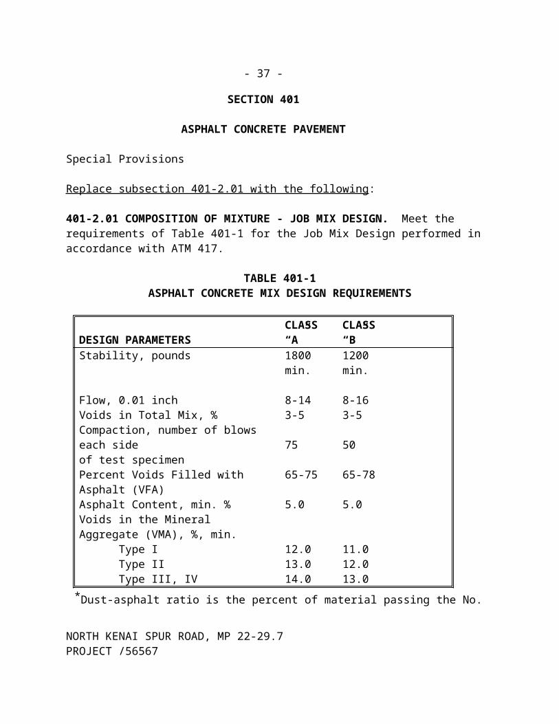
401-2.01 COMPOSITION OF MIXTURE - JOB MIX DESIGN. Meet the requirements of Table 401-1 for the Job Mix Design performed in accordance with ATM 417.
TABLE 401-1ASPHALT CONCRETE MIX DESIGN REQUIREMENTS
DESIGN PARAMETERSCLASS“A”
CLASS“B”
Stability, pounds 1800 min. 1200 min.
Flow, 0.01 inch 8-14 8-16Voids in Total Mix, % 3-5 3-5Compaction, number of blows each side of test specimen 75 50Percent Voids Filled with Asphalt (VFA) 65-75 65-78Asphalt Content, min. % 5.0 5.0Voids in the Mineral Aggregate (VMA), %, min. Type I Type II Type III, IV
12.013.014.0
11.012.013.0
*Dust-asphalt ratio is the percent of material passing the No. 200 sieve divided by the percent of effective asphalt (calculated by weight of mix).
The approved Job Mix Design will specify the target values for gradation, the target value for asphalt cement content, the Maximum Specific Gravity (MSG) of the mix, the additives, and the allowable mixing temperature range.
Target values for gradation in the Job Mix Design must be within the broad band limits shown in Table 703-3, for the type of asphalt concrete pavement specified but asphalt concrete mixture will
NORTH KENAI SPUR ROAD, MP 22-29.7PROJECT /56567

- 28 -
have the full tolerances in Table 401-2 applied for evaluation in accordance with 401-4.03 except the tolerances for the largest sieve specified will be plus 0% and minus 1%, and the #200 sieve is limited by the broad band limits.
Do not produce asphalt concrete mixture for payment until the Engineer approves the Job Mix Design. Do not mix asphalt concrete mixtures produced from different plants.
Use Asphalt Concrete Type II, Class B, minimum, for temporary pavement.
Submit the following to the Engineer at least 15 days before the production of asphalt concrete mixture:
1. A letter stating the location, size, and type of mixing plant, the proposed gradation for the Job Mix Design, gradations for individual stockpiles with supporting process quality control information, and the blend ratio of each aggregate stockpile. The proposed gradation must meet the requirements of Table 703-3, for each type of asphalt concrete pavement specified in the Contract.
2. Representative samples of each aggregate (coarse and/or intermediate, fine, and natural blend material) in the proportions required for the proposed mix design. Furnish a total of 500 pounds of material.
3. Five separate 1-gallon samples of the asphalt cement proposed for use in the mixture. Include name of product, manufacturer, test results of the applicable quality requirements of subsection 702-2.01, manufacturer's certificate of compliance according to subsection 106-1.05, a temperature viscosity curve for the asphalt cement or manufacturer's recommended mixing and compaction temperatures, and current Material Safety Data Sheet.
4. One sample, of at least 1/2 pint, of the anti-strip additive proposed, including name of product, manufacturer, and manufacturer's data sheet, and current Material Safety Data Sheet.
The Engineer will then evaluate the material and the proposed gradation using ATM 417 and the requirements of Table 401-1 for the appropriate type and class of asphalt concrete pavement specified and establish the approved Job Mix Design, which will become a part of the Contract.
The Engineer will assess a fee of $2,500.00 under Item 401(6), Asphalt Price Adjustment, for each mix design subsequent to the approved Job Mix Design for each Type and Class of Asphalt Concrete Pavement specified.
NORTH KENAI SPUR ROAD, MP 22-29.7PROJECT /56567

- 29 -
No payment for asphalt concrete pavement for which a new Job Mix Design is required, will be made until the new Job Mix Design is approved. Approved changes apply only to asphalt concrete mixture produced after the submittal of the changes.
Changes. Failure to achieve results conforming to Table 401-1 or changes in the source of asphalt cement, source of aggregates, aggregate quality, aggregate gradation, or blend ratio, will require a new Job Mix Design. Submit changes and new samples in the same manner as the original submittal.
Replace subsection 401-2.02 with the following:
401-2.02 AGGREGATES. Conform to subsection 703-2.04.
Use a minimum of three stockpiles for crushed asphalt concrete aggregate (coarse, intermediate, and fine). Place blend material in a separate pile.
401-2.03 ASPHALT MATERIALS. Delete the second paragraph and substitute the following.
Provide test reports for each batch of asphalt cement showing conformance to the specifications in Section 702 before deliver to the project. Document the storage tanks used for each batch on the test report, the anti-strip additives required by the mix design be added during load out for delivery to the project, and a printed weight ticket for anti-strip is included with the asphalt cement weight ticket. The location where anti-strip is added may be changed with the written approval of the Engineer.
Furnish the following documents at delivery:
1. Manufacturer’s certificate of compliance (106-1.05).2. Conformance test reports for the batch (Section 702).3. Batch number and storage tanks used.4. Date and time of load out for delivery.5. Type, grade, temperature, and quantity of asphalt cement loaded.6. Type and percent of anti-strip added.
401-2.05 PROCESS QUALITY CONTROL. Add the following to the first paragraph: Provide copies of these test results to the Engineer within 24 hours.
NORTH KENAI SPUR ROAD, MP 22-29.7PROJECT /56567

- 30 -
CONSTRUCTION REQUIREMENTS
401-3.01 WEATHER LIMITATIONS. Replace the last sentence with the following: Do not place asphalt concrete mixture unless the roadway surface temperature is 40 F or warmer.
401-3.03 ASPHALT MIXING PLANT. Replace the second sentence in the second paragraph with the following: Provide a tap on the asphalt cement supply line just before it enters the plant (after the 3-way valve) for sampling asphalt cement.
Delete the last paragraph:
401-3.05 ASPHALT PAVERS. Replace the third sentence in the first paragraph with the following: Use a 30 foot minimum ski, or other approved grade follower, to automatically actuate the paver screed control system.
Delete the second paragraph.
401-3.07 PREPARATION OF EXISTING SURFACE. Replace the second sentence in the first paragraph with the following: Clean out loose material from cracks wider than 1 inch (+1 inch) in width full depth then fill using asphalt concrete tamp in place. Clean, wash, and sweep existing paved surfaces of loose material. The Engineer must approve existing surface before applying tack coat.
Replace subsection 401-3.08 with the following:
401-3.08 PREPARATION OF ASPHALT. Provide a continuous supply of asphalt cement to the asphalt mixing plant at a uniform temperature, within the allowable mixing temperature range.
401-3.09 PREPARATION OF AGGREGATES. Replace the second paragraph with the following: Heat the aggregate for the asphalt concrete mixture to a temperature specified in the mix design.
401-3.12 PLACING AND SPREADING. Add the following to the first paragraph: The maximum compacted lift thickness allowed is 3 inches.
Replace the fifth paragraph with the following:
Do not pave against new Portland concrete curbing until it has cured for at least 72 hours.
NORTH KENAI SPUR ROAD, MP 22-29.7PROJECT /56567

- 31 -
401-3.13 COMPACTION. Replace the first sentence in the third paragraph with the following: Acceptance testing for density will be performed according to WAQTC FOP for AASHTO T 166/T 275 using a 6 inch diameter core.
401-3.14 JOINTS. Delete the first paragraph and substitute the following: Minimize the number of joints to ensure a continuous bond, texture, and smoothness between adjacent sections of the pavement.
Replace the last paragraph with the following: Seal the vertical edge of longitudinal joints with Crafco 34524 Joint Adhesive or approved equal before paving against it. Apply a 1/8 inch thick band of joint adhesive over the surface according to manufacturer’s recommendations.
For the top layer of asphalt concrete pavement, the minimum specification limit for longitudinal joint density is 91% of the MSG of the panel completing the joint. Cut one 6 inch diameter core centered on the longitudinal joint at each location the panel completing the joint is cored for acceptance density testing. Density will be determined according to WAQTC FOP for AASHTO T 166/T 275.
Seal the pavement surface 12 inches on each side of the longitudinal joints while the pavement is clean, free of moisture, and before traffic marking with GSB-78 (from Asphalt Systems), or approved equal.
401-3.15 SURFACE TOLERANCE. Add the following:
The Engineer will measure the surface smoothness of the top layer of asphalt concrete pavement in the driving lanes with an inertial profiler before final acceptance of the project. Remove and replace, or grind smooth any area of final pavement surface that does not meet straight edge tolerances. ***deleted*** Costs associated with meeting surface tolerances are subsidiary to the Asphalt Concrete pay item.
After completion of corrective work, the Engineer will measure the pavement surface in the driving lanes a second time for a smoothness price adjustment. No measurements will be taken in turn lanes, lane transitions, or within 25 feet of manholes, or existing pavement.
Smoothness will be measured in both wheel paths of each lane and reported as profilograph results (PrI) filtered with a 0.2 inch blanking band. Report PrI as a job average for measured lanes, calculated to the nearest 0.1 inch.
NORTH KENAI SPUR ROAD, MP 22-29.7PROJECT /56567

- 32 -
401-4.01 METHOD OF MEASUREMENT. Replace Asphalt Concrete with the following:
Asphalt Concrete. By weighing, no deduction will be made for the weight of asphalt cement or anti-stripping additive, or by the area of final pavement surface.
Delete the subparagraphs titled Anti-Strip Additive and Job Mix Design.
Replace subsection 401-4.02 with the following:
401-4.02 ACCEPTANCE SAMPLING AND TESTING. The quantity of each type of asphalt concrete mixture produced and placed will be divided into lots and the lots evaluated individually for acceptance.
A lot will normally be 5,000 tons. The lot will be divided into sublots of 500 tons; each randomly sampled and tested for asphalt cement content, density, and gradation according to this subsection. If the project has more than 1 lot, and less than 8 additional sublots have been sampled at the time a lot is terminated, either due to completion of paving operations or the end of the construction season (winter shutdown), the material in the shortened lot will be included as part of the prior lot. The price adjustment computed, according to subsection 401-4.03, for the prior lot will include the samples from the shortened lot.
If 8 or 9 samples have been obtained at the time a lot is terminated, they will be considered as a lot and the price adjustment will be based on the actual number of test results (excluding outliers) in the shortened lot.
If the contract quantity is between 1,500 tons and 4,999 tons, the contract quantity will be considered one lot. The lot will be divided into sublots of 500 tons and randomly sampled for asphalt cement content, density, and gradation according to this Subsection. Hot mix asphalt quantities of less than 300 tons remaining after dividing the lot into sublots will be included in the last sublot, hot mix asphalt quantities of 300 tons or greater will be treated as an individual sublot. The lot will be evaluated for price adjustment according to Subsection 401-4.03 except as noted.
For contract quantity of less than 1,500 tons (and for temporary pavement), hot mix asphalt will be accepted for payment based on the Engineer's approval of a Job Mix Design and the placement and compaction of the hot mix asphalt to the specified depth and finished surface requirements and tolerances. Remove and replace any hot mix asphalt that does not conform to the approved Job Mix Design.
Any area of finished surface that is visibly segregated, fails to meet surface tolerance requirements is considered unacceptable according to subsection 105-1.11.
NORTH KENAI SPUR ROAD, MP 22-29.7PROJECT /56567

- 33 -
1. Asphalt Cement. Samples for the determination of asphalt cement content will be taken from either the windrow in front of the paver, or at the end of the auger, or behind the screed before initial compaction. Two separate samples will be taken, one for acceptance testing and one held in reserve for retesting if applicable. At the discretion of the Engineer, asphalt cement content will be determined according to ATM 405 o WAQTC FOP for AASHTO T308.
2. Asphalt Cement Quality. The Contractor shall sample asphalt cement form the asphalt cement supply line when requested, witnessed by the Engineer’s representative. After purging residual asphalt cement, take 3 one-quart samples into wide mouth one quart metal containers. Asphalt cement will be sampled for acceptance testing according to WAQTC FOP for AASHTO T 40 and tested for conformance to specifications in Section 702. Three separate samples will be taken, one for acceptance testing, one for Contractor retesting, and one held in reserve for referee testing.
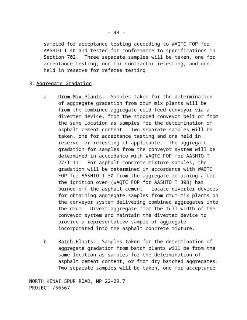
3. Aggregate Gradation.
a. Drum Mix Plants. Samples taken for the determination of aggregate gradation from drum mix plants will be from the combined aggregate cold feed conveyor via a diverter device, from the stopped conveyor belt or from the same location as samples for the determination of asphalt cement content. Two separate samples will be taken, one for acceptance testing and one held in reserve for retesting if applicable. The aggregate gradation for samples from the conveyor system will be determined in accordance with WAQTC FOP for AASHTO T 27/T 11. For asphalt concrete mixture samples, the gradation will be determined in accordance with WAQTC FOP for AASHTO T 30 from the aggregate remaining after the ignition oven (WAQTC FOP for AASHTO T 308) has burned off the asphalt cement. Locate diverter devices for obtaining aggregate samples from drum mix plants on the conveyor system delivering combined aggregates into the drum. Divert aggregate from the full width of the conveyor system and maintain the diverter device to provide a representative sample of aggregate incorporated into the asphalt concrete mixture.
b. Batch Plants . Samples taken for the determination of aggregate gradation from batch plants will be from the same location as samples for the determination of asphalt cement content, or from dry batched aggregates. Two separate samples will be taken, one for acceptance testing and one held in reserve for retesting if applicable. Dry batched aggregate gradations will be determined in accordance with WAQTC FOP for AASHTO T 27/T 11. For asphalt concrete mixture samples, the aggregate gradation will be determined in accordance with WAQTC
NORTH KENAI SPUR ROAD, MP 22-29.7PROJECT /56567

- 34 -
FOP for AASHTO T 30 from the aggregate remaining after the ignition oven (WAQTC FOP for AASHTO T 308) has burned off the asphalt cement.
4. Density. Cut full depth core samples from the finished asphalt concrete pavement within 24 hours after final rolling. Neatly cut one 6 inch diameter core sample with a core drill from each sublot at the randomly selected location marked by the Engineer. Use a core extractor to prevent damage to the core. The Engineer will determine the density of the core samples in accordance with WAQTC FOP for AASHTO T 166/T 275. Do not core asphalt concrete pavement on bridge decks. Backfill and compact all voids left by coring with new asphalt concrete mixture within 24 hours.
5. Retesting. A retest of any sample outside the limits specified in Table 401-2 may be requested provided the quality control requirements of 401-2.05 are met. Deliver this request in writing to the Engineer within 7 days of receipt of the initial test result. The Engineer will mark the sample location for the density retest. The original test results for gradation, asphalt cement content, or density will be discarded and the retest result will be used in the price adjustment calculation regardless of whether the retest result gives a higher or lower pay factor. Only one retest per sample is allowed. Except for the first lot, gradation or asphalt cement content retesting of the sample from the first sublot of a lot will include retesting for the MSG.
401-4.03 EVALUATION OF MATERIALS FOR ACCEPTANCE. Replace the first sentence with the following: The following method of price adjustment will be applied to each type of Asphalt Concrete Pavement for which the contract quantity equals or exceeds 1,500 tons, except as specified in subsection 401-4.02.
Replace the fifth paragraph with the following: The Engineer will reject asphalt concrete mixture that appears to be defective based on visual inspection. A minimum of two samples will be collected from the rejected mixture and tested if requested. If all test results are within specification limits, payment will be made for the mixture. If any of the test results fail to meet specifications, no payment will be made and the cost of the testing will be subtracted under Item 401(6), Asphalt Price Adjustment. Costs associated with removal and disposal of the rejected asphalt concrete mixture are subsidiary to the Asphalt Concrete pay item.
Add the following note after Table 401-2
Tolerances for the No. 200 sieve may not exceed the broad band limits in Table 703-3.
NORTH KENAI SPUR ROAD, MP 22-29.7PROJECT /56567

- 35 -
Replace the PAB with the following:
PAB = Price Adjustment Base = $38.75 per ton
***deleted******deleted******deleted***
Add the following subsections:
401-4.04 EVALUATION OF ASPHALT CEMENT.Asphalt cement will be randomly sampled and tested every 200 tons and evaluated for price adjustment. If the last sample increment is 100 tons or less, that quantity of asphalt cement will be added to the quantity represented by the previous sample and the total quantity will be evaluated for price adjustment. If the last sample increment is greater than 100 tons, it will be sampled, tested and evaluated separately. Asphalt cement pay reduction factors for each sample will be determined from Table 401-4.
The total asphalt cement price adjustment is the sum of the individual sample price adjustments and will be subtracted under Item 401(6), Asphalt Price Adjustment.
NORTH KENAI SPUR ROAD, MP 22-29.7PROJECT /56567

- 36 -
Table 401-4ASPHALT CEMENT PAY REDUCTION FACTORS
(Use the single, highest pay reduction factor)
Spec Pay Reduction Factor (PRF)
0 0.04 0.05 0.06 0.07 0.08 0.1 0.25 Reject orEngr Eval
Tests On Original BinderViscosity <3 Pa-s <3 >3
Dynamic Shear >1.00 kPa >1.00 0.99-0.88 0.87-0.71 0.70-0.50 <0.50
Toughness >110 in-lbs >93.5 90.0-93.4 85.0-89.9 80.0-84.9 75.0-79.9 70.0-74.9 <70.0
Tenacity >75 in-lbs >63.8 61.0-63.7 58.0-60.9 55.0-57.9 52.0-54.9 48.0-51.9 <48.0
Tests On RTFOMass Loss <1.00 % <1.00 1.001-1.092 1.093-1.184 1.185-1.276 >1.076
Dynamic Shear >2.20 kPa >2.20 2.199-1.816 1.815-1.432 1.431-1.048 <1.048
Test On PAVDynamic Shear <5000 kPa <5000 5001-5289 5290-5578 5579-5867 >5867
Creep Stiffness, S <300 MPa <300 301-338 339-388 389-450 >450Creep Stiffness, m-value >0.300 >0.300 0.299-0.287 0.286-0.274 0.273-0.261 <0.261
Direct Tension >1.0 % >1.0 0.99-0.86 0.85-0.71 0.70-0.56 <0.56
Asphalt Cement Price Adjustment for each sample = 5 x PAB x Qty X PRFPAB = Price Adjustment BaseQty = Quantity of asphalt cement represented by asphalt cement samplePRF = Pay Reduction Factor from Table 401-4
Asphalt Cement Appeal Procedure
Once notified of a failing test result of an asphalt cement sample, the Contractor has 21 day s to issue a written appeal. The appeal must be accompanied by all of the Contractor’s quality control test results and a test result of Contactor’s sample of this lot tested by an AASHTO accredited asphalt laboratory (accredited in the test procedure in question). The Engineer will review these test results and using ASTM D3244 determine a test value upon which to base a price reduction.
If the Contractor challenges this value, then the referee sample held by the engineer will be sent to a mutually agreed upon independent AASHTO accredited laboratory for testing. This test result will be incorporated into the ASTM D3244 procedure to determine a test value upon which to base a price reduction. If this final value incurs a price adjustment, the Contractor under Item 401(6) Asphalt Price Adjustment, shall pay the cost of testing the referee sample.
NORTH KENAI SPUR ROAD, MP 22-29.7PROJECT /56567
- 37 -
The total Asphalt Price Adjustment is the sum of all the price adjustments for each lot.
401-4.05 EVALUATION OF PAVEMENT FOR SMOOTHNESS.
The top layer of asphalt concrete pavement will be measured in accordance with 401-3.15 and evaluated for a smoothness price adjustment. The Engineer will calculate the smoothness price adjustment as follows:
Smoothness Price Adjustment = PAB x PQ x SFPAB = Price Adjustment Base (401-4.03)PQ = Final quantity of Asphalt Concrete Mixture, tonsPrI = Final measured pavement smoothness, inches/mileSF = Smoothness Factor
If the PQ is less than 1,500 tons, the SF = 0If the PQ is 1,500 to 5,000 tons, the SF = 0.1166 – (0.01666 x PrI)If the PQ is greater than 5,000 tons, the SF = 0.0583 – (0.0083 x PrI)
The smoothness price adjustment will be applied under Item 401(6), Asphalt Price Adjustment.
401-4.06 EVALUATION OF LONGITUDINAL JOINT DENSITY. Longitudinal joint density price adjustments apply when asphalt concrete mixture quantities are equal to or greater than 1,500 tons. A price adjustment will be based on the average of the joint densities on a project and determined as follow:
1. If project average joint density is less than 91% MSG, apply the following disincentive:
Deduct = ($1.00 per lineal foot) x (lineal feet of paved joint for the entire project) x (91 % - Project Average Joint Density %) x 100
(Note: convert density % to decimals in this equation)
2. If project average joint density is greater than 91% MSG apply the following incentive:
Add = ($1.00 per lineal foot) x (lineal feet of paved joint for the entire project) x (Project Average Joint Density % - 91%) x 100
(Note: convert density % to decimals in this equation)
NORTH KENAI SPUR ROAD, MP 22-29.7PROJECT /56567

- 38 -
The longitudinal joint price adjustment will be included in Item 401(6) Asphalt Price Adjustment.
401-5.01 BASIS OF PAYMENT. Delete the second paragraph.
Replace the third and forth paragraphs with the following: Asphalt cement, anti-stripping additives, tack coat, and crack sealing are subsidiary to the asphalt concrete pavement unless specified as pay items.
Price adjustments will not apply to:
1. Asphalt Concrete Mixture for leveling course2. Temporary Pavement
Delete the sixth paragraph
Replace the last paragraph with the following:
The Engineer will assess a fee of $2,500.00 under Item 401(6) Asphalt Price Adjustment for each mix design subsequent to the approved Job Mix Design for each Type and Class of Asphalt Concrete Pavement specified.
Add the following:
Costs associate with patching defective areas are subsidiary to 401(1A) Asphalt Concrete, Type II; Class A.
Add the following:
Pay Item No. Pay Item Pay Unit
401(1A) Asphalt Concrete Pavement, Type II; Class A Ton
(8/24/04)R199
NORTH KENAI SPUR ROAD, MP 22-29.7PROJECT /56567

- 39 -
SECTION 504
STEEL STRUCTURES
CONSTRUCTION REQUIREMENTS
Special Provision
504-3.01 FABRICATION. In subsection 8, Welding, replace item e in the second paragraph with the following:
e. Name and qualifications of NDE technicians.
NORTH KENAI SPUR ROAD, MP 22-29.7PROJECT /56567

- 40 -
SECTION 603
CULVERTS AND STORM DRAINS
Special Provisions
603-1.01 DESCRIPTION. Replace paragraph with the following: Construct or reconstruct culverts and storm drains (pipe), and repair culvert ends, to the lines and grades as shown on the Plans.
603-2.01 MATERIALS. Add the following:
Marker Posts subsection 730-2.05 and the details on the Plans.
Replace the second paragraph with the following:
When Item 603(17), Pipe, is listed in the bid schedule, furnish Corrugated Steel Pipe (CSP), Corrugate Aluminum Pipe, or Reinforced Concrete Pipe. End Sections for Metal Pipe must be of the same material as the pipe.
603-3.01 GENERAL. Add the following:
Install culvert marker posts at existing and newly install cross culverts on the highway and the pathway.
603-5.01 BASIS OF PAYMENT. Add the following to the first paragraph: Payment for repairing of culvert ends is subsidiary to 603(20-_) End Sections.
Culvert marker posts are subsidiary to 603 items.
NORTH KENAI SPUR ROAD, MP 22-29.7PROJECT /56567

- 41 -
SECTION 606
GUARDRAIL
Special Provisions
606-3.07 REMOVAL AND DISPOSAL OF EXISTING GUARDRAIL. Replace the last sentence with the following: Useable guardrail material as determined by the Engineer shall be delivered to the North Kenai Maintenance Station, at 3.2 mile Island Lake Road in Nikiski, Alaska. Notify Carl High at (907) 262-2199 one week before the planned delivery date.
606-5.01 BASIS OF PAYMENT. Add the following: Delivery of useable guardrail material to the North Kenai Maintenance Station is subsidiary to Item 606(6) Removing and Disposing of Existing Guardrail.
NORTH KENAI SPUR ROAD, MP 22-29.7PROJECT /56567
- 42 -
SECTION 608
SIDEWALKS
Special Provisions
608-1.01 DESCRIPTION. Replace the first sentence with the following: Construct asphalt or concrete sidewalks or pathways and curb ramps.
608-2.01 MATERIALS. Delete paragraph number 2 and substitute the following:
2. Asphalt Sidewalk and Asphalt Pathway
Asphalt Cement, PG 52-28 subsection 703-2.01Aggregate, Type III subsection 703-2.04
Mix Design Requirements (ATM 417)Marshall Stability, pounds, min. 1,000
Percent Voids, Total Mix 2-5Compaction, Blows/side 50
608-4.01 METHOD OF MEASUREMENT. Add the following: Asphalt pathways will be measured by the ton according to Section 109, Measurement and Payment. Asphalt cement will not be measured for payment.
Detectable Warning Tile. By each installation, complete and in place including saw cutting, ramp runs, flares, landings, detectable warning tiles, backing curb, curb and gutter and pavement necessary to provide a single street-level access.
608-5.01 BASIS OF PAYMENT. Add the following: Bed course materials, as detailed on the Plans, will be furnished placed, and paid under the respective bid items. Asphalt cement will not be paid separately but will be subsidiary to the asphalt pathway pay item.
Add the following pay items:
Pay Item No. Pay Item Pay Unit
608(7) Asphalt Pathway Ton
608(10) Detectable Warning Tile Each
NORTH KENAI SPUR ROAD, MP 22-29.7PROJECT /56567

- 43 -
SECTION 615
STANDARD SIGNSSpecial Provision
615-2.01 MATERIALS. Replace item 1 with the following:
1. Shop Drawings. Unless shop drawings have been provided in the Contract, submit shop drawings for all signs requiring the use of the Alaska Sign Design Specifications (ASDS), the Department of Transportation and Public Facilities – Sign Face Fabrication Requirements, and the Alaska Traffic Manual, letter width and spacing charts for approval before fabrication.
Replace the first paragraph under item 2 with the following: Use Type III reflective sheeting (for lettering, symbols, borders, and background) on sheet aluminum panels for all signs.
615-3.01 CONSTRUCTION REQUIREMENTS. Replace Item 7. with the following:
7. The Contractor shall notify the Engineer five (5) days before beginning sign salvage activities. The Engineer will identify those signs to be salvaged from the post. Panels will be neatly stacked in a pile and posts and associated hardware in another pile. The salvaged material shall then be inspected and approved by the Engineer. If panels, posts, or hardware are damaged the Contractor shall replace such items at no additional cost to the Department. The Contractor shall deliver salvaged material to the North Kenai Maintenance Station at 3.2 Mile Island Lake Road in Nikiski, Alaska. Notify Carl High at (907) 262-2199 one week before the planned delivery date.
Sign designated for removal but not selected for salvage shall be removed and disposed. The Contractor shall dispose of foundations from salvaged signs in a manner approved by the Engineer. If foundations are to be abandoned in place the Contractor shall remove the tops of the foundations, reinforcing steel, anchor bolts, and conduits shall be removed to a depth of not less than 12 inches below the roadway subgrade or unimproved ground, which ever applies.
615-3.02 SIGN PLACEMENT AND INSTALLATION. Add the following: Do not remove ex-isting signs unless authorized by the Engineer.
615-4.01 METHOD OF MEASUREMENT. Add the following to the first paragraph: Concrete used for sign bases is subsidiary to other work under this section.
615-5.01 BASIS OF PAYMENT. Add the following: Work for removing and relocating existing
NORTH KENAI SPUR ROAD, MP 22-29.7PROJECT /56567

- 44 -
signs, will be subsidiary to Item 615(1), Standard Sign. (09/21/04)
SECTION 618
SEEDING
Special Provisions
618-1.01 DESCRIPTION. Add the following: Seed new or disturbed slopes, ditches, and other areas directed by the Engineer. Track the soil and apply seed, mulch, fertilizer, and water. Provide a living ground cover on slopes as soon as possible.
618-2.01 MATERIALS. Add the following to the list of material specifications:
Mulch subsection 727-2.01
618-3.01 SOIL PREPARATION. Add the following: Apply seed as detailed in subsection 618-3.03 immediately after the shaping of the slopes. Prepare slopes for seed by "walking" a dozer transversely up and down the slopes, or by grading with a scarifying slope board, as determined by the Engineer. The resultant indentations shall be perpendicular to the fall of the slope. Rounding the top and bottom of the slopes is acceptable to facilitate tracking and to create a pleasing appearance, but do not disrupt drainage flow lines.
618-3.02 SEEDING SEASONS. Add the following: Seeding shall be performed between May 15 and August 15.
618-3.03 APPLICATION. Delete the second paragraph and add the following: Apply seed, mulch, and fertilizer to areas as follows. Apply seed and mulch in one application if using the hydraulic method. Apply fertilizer with the hydraulic method at least 30 days after seeding.
Seed Mix Component Ingredients Application Rate(per MSF)
Type A Seed Slender Wheatgrass (Wainwright)Red Fescue (Arctared)Annual Ryegrass (Lolium)
0.50 lbs.0.40 lbs.0.10 lbs.
Total = 1.00 lbsSoil Stabilizer
Slope ≤ 3:1Slope >3:1
MulchMulch with tackifier
46 lbs.45-58 lbs.
Fertilizer 20-20-10 12.0 lbs.
NORTH KENAI SPUR ROAD, MP 22-29.7PROJECT /56567

- 45 -
Upon the Engineer’s approval, Nortran Tufted Hairgrass may be used as a substitute for Slender Wheatgrass (Wainwright) if Slender Wheatgrass (Wainwright) is commercially unavailable. If this substitution is made, apply at the same application rate.
618-4.01 METHOD OF MEASUREMENT. Add the following: The amounts of fertilizer, mulch, and water for application used in this work, including any required reseeding, are subsidiary to other 618 items.
618-5.01 BASIS OF PAYMENT. Delete the last two sentences.
Add the following: The work described under subsection 618-3.01 Soil Preparation is subsidiary to seeding.
Water required for the hydraulic method of application is subsidiary to seeding.
Watering to prompt growth will be subsidiary to seeding.(11/06/02)R52USC
NORTH KENAI SPUR ROAD, MP 22-29.7PROJECT /56567
- 46 -
SECTION 619
SOIL STABILIZATION
Special Provision
619-1.01 DESCRIPTION. Add the following: This work also includes the furnishing, application and maintenance of hydraulically applied soil stabilization matting.
619-2.01 MATERIALS. A dd the following to the first paragraph:
Hydro Matting 727-2.04
Add the following: Hydraulically applied soil stabilization matting shall contain the seed and fertilizer specified in Section 618 Seeding. Apply matting at the same rate specified for seed in Section 618 Seeding or according to the manufacturer's written recommendations and application parameters. Where hydro matting is required by the Plans, stabilize slopes as the faces are exposed, as practical, in accordance with the NPDES Storm Water Pollution Prevention Plan. Do not expose more than 10 feet of face without applying hydro matting.
Slopes with lateral seeps shall be allowed to dry before treating with hydro matting. Treatment of such areas may be deferred until the end of slope finishing unless there is a risk of a major failure. In such event, the Engineer will direct repairs to be made by redressing and hydro matting, by rock buttressing, or by other means according to Section 641.
619-3.03 MAINTENANCE. Add the following: Hydraulically applied soil stabilization matting shall be maintained and repaired according to the manufacturer's written recommendations and subsection 618-3.04, Plant Establishment and Maintenance, or as directed by the Engineer.
619-4.01 METHOD OF MEASUREMENT. Add the following: By the square yard measured along the ground for the area designated in the Plans or as directed by the Engineer.
619-5.01 BASIS OF PAYMENT. Payment will be made under:
Pay Item No. Pay Item Pay Unit
619 (3) Hydro Matting Square Yard
NORTH KENAI SPUR ROAD, MP 22-29.7PROJECT /56567

- 47-
Delete Section 639 in its entirety and substitute the following:
SECTION 639
APPROACHES
Special Provisions
639-1.01 DESCRIPTION. Construct approaches (residential, public, or commercial) at the locations shown in the Plans.
639-2.01 MATERIALS. Use materials that conform to the standards for the main roadway.
639-3.01 CONSTRUCTION. Construct approaches to the dimensions shown on the Plans. A Temporary Construction Permit listed for approaches is found in Appendix D. The Department is continuing to obtain Temporary Construction Permits. On approaches that the Department is unable to obtain a Temporary Construction Permit, the Contractor shall limit construction activities to the Right of Way limits.
639-4.01 METHOD OF MEASUREMENT. By the number of approaches constructed as shown on the Plans or as directed. Excavation required beyond the limits of the adjacent mainline will be subsidiary.
639-5.01 BASIS OF PAYMENT. At the contract unit price shown in the bid schedule. The contract unit price for approaches shall be full compensation for furnishing equipment and labor necessary to complete the work as specified.
Materials required to construct approaches will be paid for separately under the respective items listed in the bid schedule.
Payment will be made under:
Pay Item No. Pay Item Pay Unit
639(6) Approach Each
NORTH KENAI SPUR ROAD, MP 22-29.7PROJECT /56567
- 48-
Remove and replace Section 640 with the following:
SECTION 640
MOBILIZATION AND DEMOBILIZATION
640-1.01 DESCRIPTION. Perform work and operations necessary to
1. Move personnel, equipment, supplies, and incidentals to the project site.2. Establish offices, buildings, and other facilities, except as provided under Section
644.3. Perform other work and operations and pay costs incurred before beginning
construction.4. Complete similar demobilization activities.5. Furnish required submittals such as as-builts, certifications, payroll, civil rights
reports, and equipment warranties.6. Comply with Department of Labor Meals and Lodging/Per Diem requirements.
(See Laborer’s and Mechanics’ Minimum Rates of Pay pamphlet No. 600 Issue 9 and Department of Labor (DOL) October 15, 2004 memo WHPL #197.)
640-2.01 METHOD OF MEASUREMENT
640(1) Mobilization and Demobilization
1. When 4 % of the original contract amount is earned from other bid items: 40% of the amount bid for mobilization and demobilization, or 4% of the original contract amount, whichever is less, will be paid.
2. When 8% of the original contract is earned from other bid items: an additional 40% of the amount bid for mobilization and demobilization, 4% of the original contract amount, whichever is less, will be paid.
3. The remaining balance of the amount bid for this item will be paid after submittals required under the Contract are received and approved.
640(2) Meals & Lodging/Per Diem
Progress payments for this item will be computed as equivalent to the percentage, rounded to the nearest whole percent, of the original contract amount earned.
640-3.01 BASIS OF PAYMENT. At the contract lump sum price in partial payments as described above.
NORTH KENAI SPUR ROAD, MP 22-29.7PROJECT /56567

- 49-
Payment will be made under:
Pay Item No. Pay Item Pay Unit
640(1) Mobilization and Demobilization Lump Sum
640(2) Meals & Lodging/Per Diem Lump Sum
R275USC04(10/21/04)
NORTH KENAI SPUR ROAD, MP 22-29.7PROJECT /56567

- 50-
SECTION 641
EROSION, SEDIMENT, AND POLLUTION CONTROL
Special Provisions
641-1.02 DEFINITIONS. Add the following to item No. 2.:
2. Refer to Appendix C for Erosion and Sediment Control Plan (ESCP).
641-1.03 SUBMITTALS. Replace the first sentence in the second paragraph with the following: The Department will review the above submittals within 14 working days.
NORTH KENAI SPUR ROAD, MP 22-29.7PROJECT /56567

- 51-
SECTION 642
CONSTRUCTION SURVEYING AND MONUMENTS
Special Provision
642-3.01 GENERAL. Replace the last sentence of the second to the last paragraph with the following: The notekeeper shall be thoroughly familiar with generally accepted standards of good survey notekeeping practice and the Department’s Construction Surveying Requirements (English).
Add the following: Before any work on the project, stake and reference the construction centerline horizontally and vertically. Reference the existing centerline at 100 feet intervals on tangents, and 50 feet intervals on curves, super elevations, transitions and cross-slopes. The reference stake shall be a minimum of 2 inches x 2 inches by 2 feet and shall show the offset distance to centerline and the station from the beginning of the project.
Install a reference sign every 500 feet. These reference signs shall meet the following requirements:
1. mounted a minimum of 5 feet above the shoulder,
2. located a minimum of 10 feet from the edge of shoulder,
3. marked with the station from the beginning of the project, in 5 inches high black lettering on an orange background.
NORTH KENAI SPUR ROAD, MP 22-29.7PROJECT /56567

- 52-
Add the following after item 10:
11. Measure and document the actual intersection sight distance triangles at public intersections and driveways. Measure this after paving, guardrail, and other work affecting intersection sight distance has been completed. List the actual sight distance available up to 650 feet. Note locations with greater than 650 feet of sight distance as “650’+”. Measure sight distance triangles as shown in the following figure by setting up an instrument at the driver’s eye location. Provide the results in a table format as shown. Include remarks in a “notes” column, relating minor obstacles or observations that may assist in improving sight distance. Certify and record the results on standard “letter” sized paper and provide two copies to the Engineer at least two weeks before submitting shop drawings for permanent signing. The Engineer will forward one copy to the Regional Traffic Engineer. The Regional Traffic Engineer’s office will take up to two (2) weeks to review and require any additional warning signs for intersections or driveways as needed. (02/18/04)R269USC
NORTH KENAI SPUR ROAD, MP 22-29.7PROJECT /56567

- 53-
NORTH KENAI SPUR ROAD, MP 22-29.7PROJECT /56567

- 54-
Intersection Sight Distance Survey Table
ROAD NAME:___________________________________________________Stationing FROM:______________________________ DATE:_____________
TO: _________________________________Surveyor:____________________
Public Approach or Estimated
Driveway Station
Posted Speed Limit
(Main Rd)
Sight Distance
Back (Left)
Sight Distance Ahead (Right)
Remarks
Other Notes:1.2.3.Accepted By: _____________________________________________Date: ______________
DOT/PF Project Engineer
Intersection Warning Signing Review Checked By:_______________________________________ Date: _______________
DOT/PF Regional Traffic Engineer
NORTH KENAI SPUR ROAD, MP 22-29.7PROJECT /56567

- 55-
12. Measure and document available passing sight distance along the roadway in both directions of travel. Measure this after the paving, guardrail, and other work affecting intersection sight distance has been completed. Use Table 642-1 to establish Minimum Passing Sight Distance. Move forward alongside the centerline or edge of traveled way in order to spot check and discover locations where the Minimum Passing Sight Distance drops below what is required for 10 MPH over the posted speed limit. Record the sight distance for each station location that falls below the posted speed limit plus 10 MPH. Continue to record the sight distance for each station location until the sight distance drops below what is required for the posted speed limit. Stations observed to exceed the values required for posted speed limit plus 10 MPH should be marked as “Pass” or “+”. Stations observed to fall below the values required for the posted speed limit should be marked as “Fail” or “-”.
Measure from the roadway edge of traveled way, using a 3.5-foot object height (or “instrument height”) at 100-foot station marks looking ahead to a 3.5-foot target height at the edge of traveled way for opposing traffic. Provide a list of each station result for each direction of travel along the roadway edge of traveled way. Certify and record the results on standard “letter” sized paper and provide two copies to the Engineer at least two (2) weeks before laying out final pavement markings.
The Engineer will forward one copy to the Regional Traffic Engineer. Table 642-1 does not automatically ensure passing striping will be provided. The Regional Traffic Engineer’s office will take up to two weeks to review and approve pass/no-pass striping against operating speeds for the roadway before installation, using Table 642-1 and the Alaska Traffic Manual as a guide. No-pass striping zones shall be at least 500 feet in length. Passing striping shall be long enough to meet the distances in Table 642-1. Passing striping will not extend into a segment of road without minimum sight distance. (06/07/04)R61USC02
TABLE 642-1PASSING SIGHT DISTANCE
Operating Speed (mph) Minimum Passing Sight Distance (ft)15 22020 29525 36530 44035 51540 58545 66050 73555 80560 88065 955
NORTH KENAI SPUR ROAD, MP 22-29.7PROJECT /56567

- 56-
Passing Sight Distance Survey Table
ROAD NAME:___________________________________________________Stationing FROM:______________________________ DATE:_____________
TO: _________________________________Surveyor:____________________
Project StationPostedSpeedLimit
Direction ofTravel
SightDistanceAhead
Remarks
Other Notes:
1.2.3.
Accepted By: _____________________________________________Date: ______________DOT/PF Project Engineer
Passing Sight Distance Review Checked By:______________________________________Date: ______________
DOT/PF Regional Traffic Engineer
NORTH KENAI SPUR ROAD, MP 22-29.7PROJECT /56567
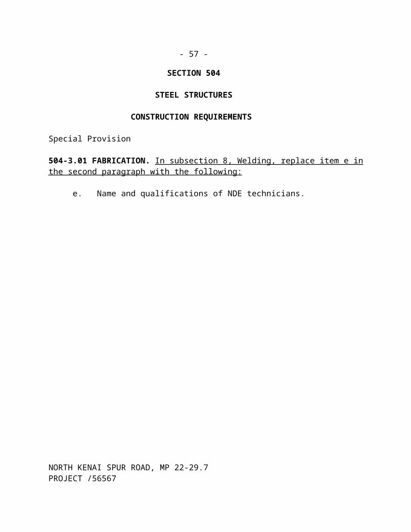
- 57-
642-4.01 METHOD OF MEASUREMENT. Replace the last sentence of the first paragraph with the following: Work associated with preparing and recording the Monument Record Forms is subsidiary to Item 642(9) Reference Existing Monument. Payment for Item 642(9) will not be credited to the Contractor until the Monument Record Forms are prepared and recorded in the local Recorder’s Office.(05/16/03)R269USC
Add the following:
Item 642(15) Intersection Sight Distance Measurement. By each intersection measured, only after the Engineer has accepted the certified and recorded results. (02/18/04)R269USC
Item 642(16) Passing Sight Distance Measurement. By the number of stations on the project measured separately along centerline, once for each direction, only after the certified and recorded results have been accepted by the Engineer. (02/18/04)R61USC02
642-5.01 BASIS OF PAYMENT.
Add the following pay items:
Pay Item No. Pay Item Pay Unit
642(15) Intersection Sight Distance Measurement Each
642(16) Passing Sight Distance Measurement Station
NORTH KENAI SPUR ROAD, MP 22-29.7PROJECT /56567

- 58-
SECTION 643
TRAFFIC MAINTENANCE
Special Provisions
643-1.03 TRAFFIC CONTROL PLAN. Replace the last paragraph with the following: The Contractor may request in writing a waiver of regulation 17 AAC 25 regarding oversize and overweight vehicle movements within this project. Movements of oversize and overweight vehicles in or near traffic within the project limits will be done according with the provisions of an approved Traffic Control Plan. A minimum 12 feet lateral separation shall be maintained between the non-street legal vehicles and the motoring public. The Traffic Control Plan shall specify the traffic control devices that will be required for these operations.
643-2.01 MATERIALS.
Add the following:
17. Flexible Markers . Refer to subsection 606-2.01 Materials.
Standard Modifications
643-3.01 GENERAL CONSTRUCTION REQUIREMENTS. Add the following: Immediately notify the Engineer of any traffic related accident that occurs within the project limits as soon as becoming aware of the accident. (02/05/04)E10
Special Provisions
643-3.01 GENERAL CONSTRUCTION REQUIREMENTS. Add the following: Whenever construction activity encroaches onto the safe route in a traffic control zone, the Contractor shall station a flagger at the encroachment to assist pedestrians and bicyclists past the construction activity.
643-3.02 ROADWAY CHARACTERISTICS DURING CONSTRUCTION. Add the following: The Contractor shall pave within 7 days of milling. The Contractor may maintain traffic on a gravel surface for a total of 2 miles (measured along centerline) at any one time throughout the project.
643-3.04 TRAFFIC CONTROL DEVICES. Add the following to 1. Embankments.: Close trenches and excavations at the end of each continuous work shift.
NORTH KENAI SPUR ROAD, MP 22-29.7PROJECT /56567

- 59-
Add the following to 3. Fixed Objects.: At the end of each continuous work shift remove obstructions greater than 3 inches above the nominal foreslope grading.
643-3.05 AUTHORITY OF THE ENGINEER. Add the following after the second sentence: In no case shall this time exceed 24 hours.
643-3.06 TRAFFIC PRICE ADJUSTMENT. Add the following Failure to maintain an acceptable infrastructure or traffic control plan will result in a price adjustment equal to 100 percent of the applicable rate shown in Table 643-1, for the time that the roadway or pedestrian facility is in an unacceptable condition.
Delete Table 643-1 and substitute the following:
TABLE 643-1ADJUSTMENT RATES
Published ADT Dollars/Minute of Delay/Lane
0-9,999 $30
10,000+ $40
643-3.08 CONSTRUCTION SEQUENCING. Delete the last sentence and substitute the following: ***deleted*** Unless determined by the Engineer do not restrict traffic during the times listed below.
Between 0600 to 0800 and 1600 to 1800 Monday through Friday.
Around any holiday:
a. If a holiday falls on Sunday, Monday or Tuesday, the above stipulations apply from 1200 on the Friday before the holiday to 0300 on the day after the holiday.
b. If a holiday falls on Wednesday, the above stipulations apply from 1200 on the Tuesday before the holiday to 0300 on the Thursday after the holiday.
c. If a holiday falls on Thursday, Friday or Saturday, the above stipulations apply from 1200 on the day before the holiday to 0300 on the Monday after the holiday.
Add the following: Obtain the local school bus schedule and coordinate work efforts to ensure the school buses are not delayed through the construction zone. This plan shall be submitted, as a TCP, to the Engineer for approval before the implementation of the school bus coordination plan.
Lane restrictions, if allowed, shall be conducted so that no more than a 10 minute accumulated
NORTH KENAI SPUR ROAD, MP 22-29.7PROJECT /56567
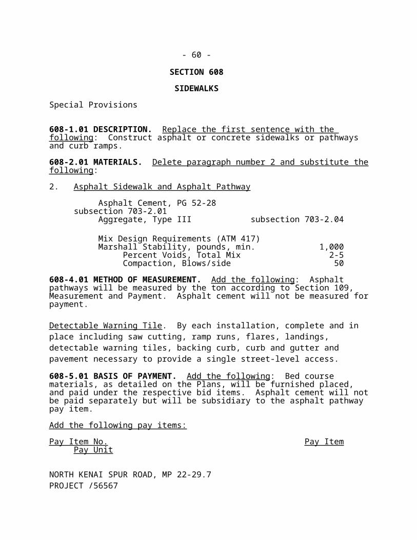
- 60-
delay is encountered by a waiting motorist through the entire length of the project, except during paving operations when 20 minutes delay will be allowed for motorists except school buses. If a queue of traffic develops at a stop, the entire queue must be emptied to include the last car that entered the queue at the time the queue was released.
Add the following subsection:
643-3.12 TEMPORARY ELECTROLIERS. If choosing to remove existing electroliers before installing and energizing the new ones, provide temporary electroliers. Make temporary electroliers operational by sunset on the day replacing or retiring the existing system, or open a roadway and/or detour to traffic.
Submit a plan for each temporary electrolier system to the Engineer for review and approval before implementing it. Allow at least two weeks for review. Provide temporary electroliers on the far right side of approaches at signalized intersections. Installation of luminaires and mast arms on the signal poles maybe allowed when they do not conflict with other overhead utilities. Along roadways, choose one of the following options for temporary lighting plan
1. When one is included, use the temporary lighting plan detailed in the Plans.
2. On roadways with existing lighting, provide new foundations and install poles and mast arms sized to keep the existing luminaires in their existing positions horizontally and vertically over the roadway. In this case, no lighting design is required.
3. Design temporary lighting system using specified types of luminaires, including the luminaires of the permanent lighting system. Use a layout pattern, mounting height, and luminaire offset and spacing that provide a light distribution that conforms to AASHTO’s “An Informational Guide for Roadway Lighting” using the luminance or illuminance method of design. Design the system for the roadway’s functional class as specified in the Department’s Annual Traffic Volume Report.
Furnish and install materials and miscellaneous hardware required to provide a functional lighting system, including foundations, branch circuitry, and electrical load centers. Size the branch conductors to provide a maximum 5% voltage drop at the most remote luminaire. Materials shall conform to the Specifications. The illumination cables maybe buried directly provided the cables are listed for direct burial.
Use the following poles.1. Existing light poles found within the project limits and scheduled to be salvaged.2. Poles from the permanent lighting system.
NORTH KENAI SPUR ROAD, MP 22-29.7PROJECT /56567

- 59 A-
3. The following new poles that the Contractor furnishes provided 30 feet difference in elevation between a luminaire and the edge of traveled way is maintained beneath it.a. ANSI Class 4 wood poles. Install outside the clear zone during winter shutdown.
To determine the clear zone, see subsection 1130.02 of the Alaska DOT/PF Highway Preconstruction Manual.
b. Steel, aluminum, or fiberglass poles that meet design criteria for 80 mph wind speeds according to AASHTO’s 1994 edition of the “Standard Specifications for Structural Supports for Highway Signs, Luminaires, and Traffic Signals”.
c. Poles that are part of the temporary signal systems.
Furnish temporary electroliers, in service from October 1 through May 15 and located within the clear zone, with an approved yielding type base. Approved yielding bases consist of FHWA approved slip bases, transformer bases, or frangible couplings. Install wood poles and other fixed base poles outside the clear zone or behind guardrail or portable concrete barrier that protects against another hazard.
Install temporary electroliers, in service from May 15 through September and located within the clear zone, with approved yielding bases or with fixed bases shielded by 30 feet of barrier and an FHWA approved end treatment. Provide two-feet of clearance between the barrier and pole. Consider the costs of furnishing the barrier and an end treatment a subsidiary obligation of Item 643(40), Temporary Electrolier. Replace fixed base poles that are located within the clear zone and that will remain in service after October 1 with yielding base poles at no expense to the State.
Use the following load centers to energize the temporary lighting and signal systems. Provide work needed to modify load centers to provide functional temporary lighting and signal systems according to the NEC.1. Permanent load centers installed in Plan location. 2. Existing load centers scheduled to remain intact until completion of the project. Relocate
and reuse existing load centers only if they are approved.3. Approved temporary load centers with photoelectrical controlled lighting circuits.
Provide a temporary load center when retiring an existing load center that is not approved, and when approved load centers are unavailable.
Approved load centers include load centers UL labeled as Service Equipment, or UL labeled as Industrial Control Equipment and marked "Suitable for use as service equipment".
643-4.01 METHOD OF MEASUREMENT. Add the following: No measurement required to provide a 24 hour toll free (1-800-###-####) "hotline road report" telephone with a prerecorded message, and weekly notices with daily updates. Work will be subsidiary to Item 643(1) or 643(2), Traffic Maintenance.
NORTH KENAI SPUR ROAD, MP 22-29.7PROJECT /56567
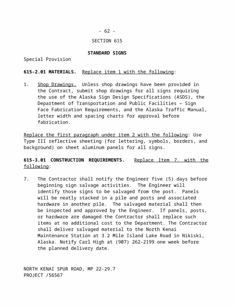
- 59 B-
***This page intentionally left blank.***
NORTH KENAI SPUR ROAD, MP 22-29.7PROJECT /56567

- 60-
643-5.01 BASIS OF PAYMENT. Add the following:
The Engineer will not require a change order/directive will for the traffic control devices pay item.
TRAFFIC CONTROL RATE SCHEDULE
Traffic Control Device Pay Unit Unit Rate
Construction Signs Each/Day $5.00Special Construction Sign Square Foot $20.00Type II Barricade Each/Day $ 3.00Type III Barricade Each/Day $ 10.00Traffic Cone or Tubular Marker Each/Day $ 1.00Drums Each/Day $ 3.00Sequential Arrow Panel Each/Day $55.00Portable Concrete Barrier Each $60.00Temporary Crash Cushion / ET-2000 LET Each $3,000.00Pilot Car Hour $65.00Watering M-Gallon $ 20.00Street Sweeping Hour $150.00Power Broom Hour $75.00Plastic Safety Fence Foot $2.50Portable Changeable Message Board Sign Calendar Day $150.00Temporary Sidewalk Surfacing Square Foot $1.15Flexible Markers Each $50.00Removal of Pavement Markings Foot $1.25Temporary Guardrail Foot $21.00Interim Pavement Markings Painted Markings Removable Preformed Markings Temporary Raised Pavement Markings Word or Symbol Markings Removal of Markings
FootFootEachEachFoot
$0.30$0.65$0.75
$40.00$1.00
NORTH KENAI SPUR ROAD, MP 22-29.7PROJECT /56567

- 61-
Payment for Item 643(15), the Engineer will pay Flagging on a contingent sum basis at the rate of $36.00/hour. The Engineer does not require a change order/directive for the flagging pay item.
No payment compensation will be made for, nor will the contract time be extended for delays resulting from incomplete, incorrect, or inadequate calculations, plans, or installation procedures.
Payment for Item 643(40) will be paid on a contingent sum basis at a rate of $2000 for each temporary electrolier. The price paid for each temporary electrolier includes full compensation for work involved in getting the Contractor’s plan and materials approved, and moving, furnishing, assembling, installing, and making each temporary electrolier operational. The price also includes full compensation for installing a foundation, removing and replacing improvements, installing conductors, maintaining the electrical system, installing temporary electrical load centers when load centers are unavailable for use, and removing the temporary electrolier and its foundation when it is no longer needed.
Payment will be made under:
Pay Item No. Pay Item Pay Unit
643(15) Flagging Contingent Sum
643(40) Temporary Electrolier Contingent Sum
(07/02/04) R222
NORTH KENAI SPUR ROAD, MP 22-29.7PROJECT /56567

- 62-
SECTION 644
SERVICES TO BE FURNISHED BY THE CONTRACTOR
Special Provisions
644-2.01 FIELD OFFICE. Delete the third fifth and seventh sentences of the first paragraph and the second paragraph in this subsection and substitute the following: Meet the following office requirements:
1. A minimum of 1,000 square feet of floor area. Divide the office area so that it contains an office room separated by a closable door. The office room shall have a minimum of 40 square feet of floor area.
2. A thermostatically controlled interior heating system with necessary fuel.
3. A minimum of four electrical outlets on two or more circuits.
4. Adequate parking for a minimum of 5 vehicles, with one disability parking space meeting the requirements of Americans with Disabilities Act Accessibility Guidelines (ADAAG).
5. Provide attached indoor plumbing with sanitary lavatory facilities and potable drinking water.
6. Three telephone lines available at the project location.
7. Located within 5 miles of the project.
8. Provide one move in and one move out for state office furniture and equipment.
644-4.01 BASIS OF PAYMENT. Add the following: Electricity, propane and water supplied for the State provided portable asphalt lab will not be paid separately. Those items are subsidiary to Item 644(2) Field Laboratory.
NORTH KENAI SPUR ROAD, MP 22-29.7PROJECT /56567

- 63-
SECTION 646
CPM SCHEDULING
Special Provisions
646-2.01 SUBMITTAL OF SCHEDULE. Delete this subsection in its entirety and replace with the following: Submit a detailed draft CPM schedule at the preconstruction conference for the Engineer’s approval. The finalized CPM schedule must be completed and accepted before any work being done on the project site.
646-3.01 REQUIREMENTS AND USE OF SCHEDULE. Delete item 2. 60-Day Preliminary Schedule.
(3/12/01)R261M98
NORTH KENAI SPUR ROAD, MP 22-29.7PROJECT /56567
- 64-
Add the following Section:
SECTION 647
EQUIPMENT RENTAL
Special Provisions
647-1.01 DESCRIPTION. This item consists of furnishing construction equipment, operated, fueled and maintained, on a rental basis for use in construction of extra or unanticipated work at the direction of the Engineer. Construction equipment is defined as that equipment actually used for performing the items of work specified and shall not include support equipment for example, but not limited to, hand tools, power tools, electric power generators, welders, small air compressors and other shop equipment needed for maintenance of the construction equipment.
The work is to be accomplished under the direction of the Engineer, and the Contractor's operations shall be according to the Engineer's instructions. These instructions by the Engineer shall be to the Contractor's supervisory personnel only, not to the operators or laborers. In no case shall these instructions by the Engineer be construed as making the Department liable for the Contractor's responsibility to prosecute the work in the safest and most expeditious manner.
647-2.01 EQUIPMENT FURNISHED. In the performance of this work, the Contractor shall furnish, operate, maintain, service, and repair equipment of the numbers, kinds, sizes, and capacities set forth on the Bid Schedule or as directed by the Engineer. The operation of equipment shall be by skilled, experienced operators familiar with the equipment.
The kinds, sizes, capacities, and other requirements set forth shall be understood to be minimum requirements. The number of pieces of each equipment to be furnished and used shall be as the Engineer considers necessary for economical and expeditious performance of the work. The equipment shall be used only at times and places as the Engineer may direct.
Equipment shall be in first-class working condition and capable of full output and production. The minimum ratings of various types of equipment shall be as manufactured and based on manufacturer's specifications. Alterations will not be considered acceptable in achieving the minimum rating. Equipment shall be replaced at any time when, in the opinion of the Engineer, their condition is below that normal for efficient output and production.
Equipment shall be fully operated, which shall be understood to include the operators, oilers, tenders, fuel, oil, air hose, lubrication, repairs, maintenance, insurance, and incidental items and expenses.
NORTH KENAI SPUR ROAD, MP 22-29.7PROJECT /56567

- 65-
647-2.02 EQUIPMENT OPERATORS AND SUPERVISION PERSONNEL. Equipment operators shall be competent and experienced and shall be capable of operating the equipment to its capacity. Personnel furnished by the Contractor shall be, and shall remain during the work hereunder, employees solely of the Contractor.
The Contractor shall furnish, without direct compensation, a job superintendent or Contractor's representative together with other personnel as are needed for Union, State, or Federal requirements and in servicing, maintaining, repairing and caring for the equipment, tools, supplies, and materials provided by the Contractor and involved in the performance of the work. Also, the Contractor shall furnish, without direct compensation, transportation as may be appropriate for the personnel.
647-3.01 CONSTRUCTION REQUIREMENTS. The performance of the work shall be according with the instructions of the Engineer, and with recognized standards and efficient methods.
The Contractor shall furnish equipment, tools, labor, and materials in the kinds, number, and at times directed by the Engineer and shall commence, continue, and stop any of the several operations involved in the work only as directed by the Engineer.
Normally, the work is to be done when weather conditions are reasonably favorable, six (6) days per week, Mondays through Saturdays, holidays excepted.
The Engineer will begin recording time for payment each shift when the equipment begins work on the project. The serial number and brief description of each item of equipment listing in the bid schedule and the number of hours, or fractions thereof to the nearest one-quarter hour, during which equipment is actively engaged in construction of the project shall be recorded by the Engineer Each day's activity will be recorded on a separate sheet or sheets, which shall be verified and signed by the Contractor's representative at the end of each shift, and a copy will be provided to the Contractor's representative.
647-4.01 METHOD OF MEASUREMENT. The number of hours of equipment operation to be paid for shall be the actual number of hours each fully operated specified unit of equipment, or each fully operated specified combination of units of equipment, is actually engaged in the performance of the specified work on the designated areas according with the instruction of the Engineer. The pay time will not include idle periods, and no payment will be made for time used in oiling, servicing, or repairing of equipment, or in making changeovers of parts to the equipment. Travel time to or from the project, will not be authorized for payment.
NORTH KENAI SPUR ROAD, MP 22-29.7PROJECT /56567

- 66-
647-5.01 BASIS OF PAYMENT. Payment for Item 647(2) at the rate shown on the bid schedule. This shall be full compensation for furnishing, operating, maintaining, servicing, and repairing the equipment, and for incidental costs related to the equipment. Furnishing and operating of equipment of heavier type, larger capacity, or higher horsepower than specified will not be entitlement to any extra compensation.
Payment will be made under:
Pay Item No. Pay Item Pay Unit
647(2) Wide Pad Dozer, 65-hp Minimum Hour
(11/12/98)R15M98
NORTH KENAI SPUR ROAD, MP 22-29.7PROJECT /56567

- 67-
SECTION 660
SIGNALS AND LIGHTING
Special Provisions
660-1.01 DESCRIPTION. Replace the first paragraph with the following: ***deleted*** Item 660 (2A) shall consist of furnishing and installing a Flashing Beacon System in the
vicinity of the Nikiski Fire Station. This work will consist of furnishing and installing two (2) flashing beacons, a controller, six (6) junction boxes, a 5C#14 conductor, 2 and 3” RMC conduit. Boring under roadway will be required to get the conductor from pole 6 to the controller mounted in the fire station.
Item 660 (2B) shall consist of furnishing and installing a Flashing Beacon System in the vicinity of the Nikiski Elementary School. This work will consist of furnishing and installing two (2) flashing beacons, two (2) junction boxes and two 2 inch RMC with 3C#8 conductors wired to the existing controllers.
Item 660 (3) consist of furnishing and installing a Highway Lighting System at various locations throughout the project. This work will consist of furnishing and installing fourteen (14) Electroliers, junction boxes, 2 and 3” RMC with 3C#8 conductors. Trenching and boring will be required to get conduit under roadway.
660-2.01 MATERIALS. Delete subitem a under item 1. Equipment List(s) and Drawings. and substitute the following:
a. Materials on the Approved Products List: The Approved Products List does not apply to the 660 items. Provide catalog cuts of materials to the Engineer for review and approval.
2. As-Built Plans. Add the following to the last paragraph. The Engineer will deliver one copy each to State Maintenance and Operations; Technical Services; and attach the appropriate sheets of the last set in clear plastic envelopes to the inside of each controller assembly and load center.
Replace subsection 660-3.01 with the following:
660-3.01 GENERAL. 1. Scheduling of Work . Complete the highway lighting system and ensure it is ready for
operation before opening to traffic the corresponding section of new alignment.
Install detector loops and underground conduit before applying new pavement.
NORTH KENAI SPUR ROAD, MP 22-29.7PROJECT /56567

- 68-
Do not pull conductors into conduit until junction boxes are set to grade, crushed rock sumps are installed, grout is placed around the conduit, and metallic conduits are bonded.
2. Safety Precautions . Before starting work on existing street lighting circuits, de-energize the system by opening disconnect switches, and/or opening bypass switch plugs, and tagging each opened device as detailed in Part 4, Section 44, Article 440 of NESC. Where identified circuits are under the control of an electric utility, obtain written assurance daily from the utility that the circuit being worked on has been de-energized.
Post suitable-signs at load centers when circuits from that load center are being worked on.
Pedestrian signals are usually arranged in pairs at a crosswalk. Ensure that only one pedestrian signal per pair is disconnected at a time. Failure to do so will cause the intersection to automatically begin flashing operation.
3. Excavating and Backfilling . Complete excavation and backfill required to install the signal and lighting components embedded in the roadway as shown in the Plans, including foundations, conduits, junction boxes, and loop detectors. Complete this work according to the requirements of Section 643. Place excavated materials where it will not interfere with surface drainage.
Support and protect conduits and utilities scheduled to remain in service when encountered during excavation.
Excavate trenches wide enough to install the number of conduits specified side by side, to provide clearances of at least 2½ -inches around two-inch conduits and at least two-inches around conduits larger than two-inches, and to compact the bedding and backfill materials according to specifications.
To install conduits, excavate trenches deep enough to allow for six inches of bedding material, the depth of the largest conduit, and the minimum burial depth specified between the top of the conduit and finished grade of the ground above the conduit. Keep the longitudinal profile of trench bottoms free of irregularities that would prevent the assembled conduit run from continuously contacting the top of the bedding material.
Dispose of, according to subsection 203-3.01, excavated material that remains after completing backfill work and excavated material not meeting the requirements of Selected Material, Type C, as defined in subsection 703-2.07.
Dewater excavations immediately before and during embedding and backfilling
NORTH KENAI SPUR ROAD, MP 22-29.7PROJECT /56567

- 69-
operations. Backfill excavations with materials that meet the following requirements:
a. Around formed foundations, use material that meets the requirements of Selected Material, Type A,
b. Within the limits of the typical section, embed conduits and backfill trenches using material that meets the requirements of the lift in which it is located, reusing excavated materials if it meets the requirements of the applicable lift,
c. In other locations, embed conduits and backfill trenches using material that meets the requirements of Selected Material, Type C, reusing excavated materials if it meets this requirement.
d. Import, when ordered, embedment and backfill materials that satisfy the preceding materials requirements.
Embed conduit(s) between two six inch lifts of material gleaned free of rocks exceeding a one-inch maximum dimension. Grade and compact the first lift to provide a surface that continuously contacts the assembled conduit run.
Within six feet of paved surfaces and around foundations, backfill in uniform layers no more than six-inches deep and compact each layer according to subsection 203-3.04. In other locations, compaction may be as approved by the Engineer.
4. Welding . Complete welding according to subsection 504-3.01.8. Welding and approved shop drawings.
Submit shop drawings of the proposed work with the welding plans for approval. The shop drawings shall include material specifications, component dimensions, the types of welds that will be made, and the proposed type and extent of weld inspection.
Repair the holes that were used to mount equipment in reused poles and mast arms by welding in disks flush with the adjoining surface. For the disk material, use steel that matches the ASTM designation, grade, and thickness of the steel used to fabricate each pole. Cut disks that match the dimensions of the hole being repaired from pieces of steel plate bent to match the pole’s radius at the hole. Grind the welds smooth and flush with the adjoining pole and disk surfaces. Repair the damaged finish according to subsection 660-3.01.8.
NORTH KENAI SPUR ROAD, MP 22-29.7PROJECT /56567

- 70-
5. Removing and Replacing Improvements . The Contractor shall complete, at the Contractor’s expense, the following work.
a. Remove improvements that need to be removed to complete the work detailed in the Plans.
b. Reconstruct with new materials the nonreusable improvements removed to complete the work, the repairs of that are not covered by other items in the Contract.
c. Replace with new materials the reusable items that the Contractor damages that are specified for reuse.
d. Reconstruct with new materials improvements the Contractor damages or removes that do not conflict with the work and are not scheduled for removal.
Nonreusable improvements consist of cast in place items, including: asphalt concrete pavement, sidewalks, curb and gutter, lawns, and traffic markings. Reusable improvements include the items that were made before they were installed. Do not reuse crushed aggregate base material as backfill in the base course if excavation depth exceeds the thickness of the base course.
Complete reconstruction work, including materials, according to the applicable sections of the Alaska SSHC, and leave the work in a satisfactory and serviceable condition. In completing the reconstruction work, match the alignments, widths, thicknesses, shapes, sizes, cross sections, and finishes of the existing improvements.
If removing a portion of sidewalk or curb and gutter, remove an entire segment between the weakened plane contraction joints or between an expansion joint and a weakened plane contraction joint.
Before removing a segment of Portland or asphalt cement concrete material, cut completely through the material with a saw along the outline of the area to be removed. Make cuts neat and true and prevent shatter outside the area removed.
To replace lawns, leave the top of the backfilled excavation low enough to install four inches of compacted topsoil. Match the top of the topsoil with the bottom of the vegetative mat. Apply seed and keep the seeded areas watered according to Section 618.
Remove, keep alive, and replant trees, shrubs, and plants according to Section 621. Replace the trees, shrubs, and plants that do not survive with plants of like size and type.
NORTH KENAI SPUR ROAD, MP 22-29.7PROJECT /56567

- 71-
6. Salvaging or Reusing Electrical Equipment . Salvage the existing Lighting Systems materials undamaged to the State Maintenance Yard at 46445 Sterling Highway in Soldotna, Alaska. Notify Brian Gabriel, Electrician, or Carl High at 907-262-2199 one week before the planned delivery date.
A controller assembly includes the cabinet and equipment contained in the cabinet before Contract award, including bus interface units, controller unit, phase selectors, load switches, flasher unit, detector amplifiers, and conflict monitor unit.
Within 15 days of the Notice to Proceed, complete an inventory of the materials that will be saved in the presence of the Engineer. Note the location and condition of the materials. When finding material specified for reuse in an unserviceable condition, the Engineer will determine whether to repair it or replace it with new material that will be paid for as extra work under subsection 109-1.05. Retain a copy of the inventory and give the original documents to the Engineer.
Remove unsaved materials from the highway right-of-way, including conduits, junction boxes, conductors, and foundations. Raze the tops of foundations abandoned in place according to subsection 660-3.02. Fill the holes left by removing junction boxes and foundations with selected material type A and compact them as directed.
With approval, after removing conductors, buried conduits that do not interfere with other construction may be abandoned with a credit taken by the Department. Remove the ends of abandoned conduits from the junction boxes that will remain in service.
Reusing the existing and State furnished equipment specified will be done at the Contractor’s expense; complete the following:
a. For relocated poles, install new foundations of the type specified and furnish new nuts, bolts, washers, and conduits needed to complete the installations.
b. For reused electroliers, including those electroliers that will remain on their foundations, install new illumination tap wires and fused disconnect kits.
c. Clean reused signal heads and luminaires inside and out.d. Install new lamps in luminaires and new light emitting diode optical units in the
signal heads.e. For relocated signal heads, furnish and install the mounting brackets needed to
complete the installations.f. For reused poles, repair the holes that were made to mount equipment according
to subsection 660-3.01.4. Welding.
NORTH KENAI SPUR ROAD, MP 22-29.7PROJECT /56567

- 72-
g. For equipment with damaged finishes, including welded hole repairs, provide a new finish on the equipment according to subsection 660-3.01.8.
h. Adjust reused junction boxes and the conduit ends in them to the new grade according to subsections 660-3.04 and 660-3.03, respectively.
If deciding to use new equipment rather than reusing the equipment specified, notify the Engineer of the change and include a submittal according to subsection 660-2.01.1.
7. Field Tests . Electrical circuits must pass the following tests before the Engineer will accept the work for payment. Perform these tests in the presence of the Engineer, and document the results of each test on a per circuit basis. Retain a copy of test results and give the original documents to the Engineer. Furnish equipment needed to perform these tests.
Replace or repair at the Contractor’s expense, and in an approved manner, faulty materials and work revealed by these tests. After making repairs, repeat tests on the repaired circuit and continue this process until circuits have passed required tests. The Department reserves the right to have circuits retested, and to use the retest results to accept or reject individual circuits.
a. Grounds. Before completing the circuitry and functional tests, physically examine conduits ends, junction box lids, load centers, and the foundations for signal posts and poles, lighting poles, and controller cabinets to ensure the grounding system required by subsections 660-3.06 and 661-3.01 has been installed and splices and connections are mechanically firm.
b. Continuity . Test each loop detector circuit for continuity at the roadside junction box before splicing the loop detector to the lead-in cable. Each loop detector must have a resistance less than 0.5 ohms.
After splicing the loop detectors to the lead-in cables, test each pair at the controller or detector cabinet. Each pair must have a value less than 5 ohms for single pair lead-in cables and 10 ohms for multi-pair lead-in cables. The continuity test ohm reading at the cabinet must be greater than the ohm reading measured for the loop detector at the junction box.
c. Insulation Resistance Test . Perform a conductor insulation (megohm) test on conductors. Complete the test between each conductor and ground and between the conductors in each cable. Disconnect lamps and magnetometer sensing probes before completing the megohm test.
NORTH KENAI SPUR ROAD, MP 22-29.7PROJECT /56567

- 73-
After splicing the loops to the lead-in cables, measure each pair in the lead-in cables at the controller or detector cabinet between one conductor and the cabinet ground rod. Insulation shall measure a minimum resistance of 100 megohms or the minimum specified by the manufacturer, measured at 500 volts DC.
d. Inductance Test . Measure each detector loop and lead-in cable system at the controller or detector cabinet. The inductance must be in the range of 50 to 500 microhenries.
e. Circuit . Energize every signal indication circuit with lamps installed before installing the load switches.
f. Functional . Perform the following tests on each lighting system after the component circuits have satisfactorily passed the tests for continuity, grounding, insulation integrity, and circuitry.
1) Perform the functional test for each highway lighting system and sign illumination system until the systems burn continuously 5 days without the photocell, followed by a 5-day operational test using the photocell.
2) Perform the functional test for each flashing beacon system for not less than 5 days of continuous, satisfactory operation.
A shut down of the electrical system due to a power interruption does not constitute discontinuity of the functional test if the system functions normally when power is returned.
8. Repairing Damaged Finishes. Examine new, reused, and State-furnished equipment for damage to its finish before putting the equipment into service. Repair the damaged finishes found according to the following:
a. Galvanized. Repair damaged areas more than 12-inches away from welds and slip fit areas, by applying a minimum 7.8 mils of zinc-based alloy applied according to ASTM A780.
If the damaged areas are within 12-inches of welds and slip fit areas, make the repair by applying a minimum 7.8 mils of zinc-rich paint applied according to ASTM A780.
b. Painted. Repair damage to painted finishes according to the following
NORTH KENAI SPUR ROAD, MP 22-29.7PROJECT /56567

- 74-
(1) Wash the equipment with a stiff bristle brush using a solution containing two tablespoons of heavy-duty detergent powder per gallon of water. After rinsing, wire brush surfaces to remove poorly bonded paint, rust, scale, corrosion, grease, or dirt. Remove dust or residue remaining after wire brushing before priming.
(2) Factory or shop cleaning methods may be used for metals if equal to the methods specified herein.
(3) Immediately after cleaning, coat bare metal with pre-treatment, vinyl wash primer, followed by 2 prime coats of zinc chromate primer for metal.
(4) Give signal equipment, excluding standards, a spot-finishing coat on newly primed areas, followed by 1 finishing coat over the entire surface.
(5) Give non-galvanized standards 2 spot-finish coats on newly primed areas.
Paint coats may be applied either by hand brushing or by approved spraying machines. Perform the work in a neat and workmanlike manner. The Engineer reserves the right to require the use of brushes for the application of paint, should the work done by the paint spraying machine prove unacceptable.
9. Regulations and Code. Complete work according to the standards of the NEC, the NESC, and local safety codes as adopted and amended by the authority having jurisdiction.
660-3.02 FOUNDATIONS. Replace the first item 1. and 2. with the following:
1. Cast-in-Place Foundations. Cast foundations for posts and poles in holes drilled at each pole’s location shown in the Plans. Use precast or cast in place foundations for cabinets. Locate the tops of traffic signal post and pole foundations flush with the adjacent finished: walkway, shoulder, or surrounding ground.
a. Form the entire controller foundation and the top 12 inches of pole or post foundations and give the top a smooth steel trowel finish.
b. Place conduits in the center of the pole-post foundations with clearance allowed for bushings. If subsurface conditions prevent completing a drilled hole, and when approved, use a corrugated metal pipe (CMP) form as a substitute for the drilled hole. Consider the savings in concrete to offset the cost of supplying and installing the CMP form. No additional payment will be made for the CMP
NORTH KENAI SPUR ROAD, MP 22-29.7PROJECT /56567

- 75-
formed foundation.
c. When a CMP is used, over excavate the area around the form enough to allow for proper compaction around the form. Perform backfill operations according to Section 204. Do not use water for drilling operations or other purposes where it may enter the hole.
d. Use controller cabinet anchor bolts as recommended by cabinet manufacturer and set with a template.
e. Place Class A concrete meeting Section 501. Place reinforcing steel meeting Section 503. If required, use corrugated steel pipe that is at least 14 gage, meeting subsection 707-2.01.
f. Drill holes or use forms that are vertical and true to the locations shown in the Plans. Before placing the form or reinforcing steel cage, remove loose material to ensure the foundation rests on firm, undisturbed ground.
g. If a reinforcing steel cage is required, place and secure it symmetrically about the vertical axis and securely block it to clear the sides of the foundation. Use a template to securely support anchor bolt assemblies and conduit ends so they do not move during concrete placement.
h. Do not permit surface water to enter the hole. Before placing concrete, remove water that may have infiltrated in the hole. Thoroughly moisten both the forms and the ground before placing concrete. Pour each foundation in one continuous pour.
i. Do not erect or place posts, poles, and pedestals on the foundation until 7 days after placing the concrete. Plumb the assembly by adjusting the nuts on the anchor bolts before attaching the galvanized skirt.
j. Replace, with no additional compensation, finished foundations with anchor bolts that do not match the base plate of the pole or are out of plumb. Do not modify the anchor bolts or base plate to get the base plate set on the leveling nuts.
NORTH KENAI SPUR ROAD, MP 22-29.7PROJECT /56567

- 76-
k. Install the bottoms of the bottom leveling nuts in a level plane within one-inch of the top of foundations. Generously lubricate the bearing surface and internal threads of top nuts with beeswax and tighten the top nuts according to the anchor bolt tightening procedure included in the contract documents.
l. Attach a 4 AWG, bare, solid copper wire as a grounding electrode conductor to the #4 spiral bar in the reinforcing steel cage. Use an irreversible compression connector or cadweld to make the attachment. Protect the attachment during concrete placement. In foundations that lack reinforcing steel cages, install 21 feet of coiled 4 AWG, bare, solid copper wire as the grounding electrode. Route the conductor to protrude near the top, center of the foundations. Slide a minimum six inch long, nonmetallic, protective sleeve over the conductor. Allow one inch of the sleeve and 24 inches of conductor to protrude from the foundations.
2. Pile Foundations. Not to be used on this project.
Replace subsection with 660-3.03 with the following:
660-3.03 CONDUIT. Install electrical conductors in conduit, except for overhead wiring, wiring inside poles, and when otherwise specified. Use rigid metal conduits (RMC) and fittings for raceways, including bored casings. Install conduits of the sizes specified along the routes detailed on the Plans. When routing is not shown, route conduits as directed by the Engineer.
1. Install conduits at least 30 inches below the finished grade of the ground above the conduit, except conduits that will be sealed under a minimum 4 inch thick Portland cement concrete sidewalk may be installed a minimum of 18 inches below the top back of curb or surface above the conduit, whichever is lower.
2. Install conduits that cross unpaved-areas and paved roadways that will be overlaid in excavated trenches. Excavate, bed conduits, and backfill trenches according to subsection 660-3.01.3, Excavating and Backfilling.
3. Install conduit(s) under paved roadways and approaches that will not be overlaid by jacking them under pavements up to 30 feet wide and by boring or drilling methods under pavements greater than 30 feet wide.
4. Sweep conduits, except loop detector tails, through the open bottom of junction boxes by installing 90 degree elbows on the ends of conduit runs. To each elbow, install a nipple that terminates 5 to 12 inches above the bottom edge of each junction box.
NORTH KENAI SPUR ROAD, MP 22-29.7PROJECT /56567

- 77-
5. Install the tails of loop detectors without elbows through the walls of junction boxes at elevations that ensure the loops drain into the box. Extend the ends a minimum of 2 inches beyond the inside wall of the box.
6. Drill a 3/8-inch drain hole in the bottom of the lower straight section of elbows and in the bottom of conduits at the low points of conduit runs. Smooth the edges of the drilled holes on the inside of elbows to prevent scraping the conductors. Cover the holes with a wrap of approved filter cloth secured with two self-clinching nylon cable ties.
7. Keep conduits clean at all times. Install grounding bushings and approved plastic insert type plugs on the ends of conduit runs before backfilling around the conduit ends.
8. At the low points of conduit runs, install sumps containing a minimum 2 cubic feet of coarse concrete aggregate material that conforms to subsection 703-2.02. Compact the aggregate sumps as directed to prevent settlement of the trench backfill.
9. Install conduits that must cross existing facilities such as storm drain pipes, duct systems, and other underground utilities at the minimum depths specified, going under the facilities if necessary. Install additional drains and aggregate sumps at the low spots, if any.
10. Position conduits in trenches, junction boxes, and foundations to provide clearances of at least 2½ inches around two inch conduits and at least 2 inches around conduits larger than 2 inches.
11. Fabricate conduits less than 10 feet long from standard lengths of conduit. Cut conduits squarely to ensure the threading die starts squarely on the conduit. Cut the same number of threads as found on the factory threaded ends. Ream the inside of conduit-ends cut in the shop or field to remove burrs and sharp edges. Do not use slip joints or pieces of running thread pipe.
12. Coat drilled holes, shop and field cut threads, and the areas with damaged zinc coating with zinc rich paint.
13. When standard couplings cannot be used to join conduit components, use approved threaded unions.
NORTH KENAI SPUR ROAD, MP 22-29.7PROJECT /56567
- 77A-
14. Bury a continuous strip of 4 mils thick, six inch wide polyethylene marker tape above underground conduit runs. Install the tape 9 inches (± 3 inches) below finished grade, using two strips side by side to mark road crossings. Furnish tapes with a black legend on a red background.
15. If encountering obstructions during jacking or drilling operations, obtain approval and cut small holes in the pavement to clear the obstruction. Locate the bottom inside face of the bore pit no closer than the catch point of a 1-¼ to 1 slope (a horizontal to vertical ratio) from the edge of pavement. Do not leave these pits unattended until an approved means of protection has been installed.
16. In foundations, install 90 degree elbows and conduits of the size and quantity shown on the Plans. Extend the conduits a maximum of 2 inches above the top of the foundations for posts and poles with breakaway bases and 4 inches above the top of foundations for fixed base structures.
17. Seal conduits leading to electrical equipment mounted on soffits, walls, and other locations below the grade of the serving junction box with an approved duct sealing compound.
18. Install expansion fittings in conduits that cross expansion joints.
19. Install a polypropylene pull rope with a minimum 200 pound tensile strength in future use or spare conduits, and reinstall the plugs. Double back at least two feet of pull rope into both ends of each conduit.
20. Conduits larger than the sizes specified may be installed. If used, it must be for the entire length of the run. Reducing couplings or bushings are not allowed. Complete work associated with installing conduits larger than specified without extra compensation.
21. When the Plans specify using rigid non-metallic conduit, install RMC in structures and foundations, between type 2 and 3 load centers and the nearest junction box, and on the surfaces of poles and other structures.
22. Clean existing conduits that will remain in service using a heavy-duty air compressor that delivers at least 125 cubic feet of air per minute at a pressure of 110 pounds per square inch. Clean the conduits before pulling in new cables and after removing cables specified to be removed or replaced as follows:
NORTH KENAI SPUR ROAD, MP 22-29.7PROJECT /56567

- 77B-
When the conduits contain cables that will remain in service, leave the cables in place during the cleaning, and
Ream empty conduits with a mandrel or cylindrical wire brush before blowing them out with compressed air.
23. When modifying existing conduit runs, complete the work as required for new installations using the same sizes and types of conduit. When extending existing conduits, add no more than 90 degrees of horizontal bend to the extension.
24. When installing a junction box in a continuous run of existing conduit, remove a length of conduit in each conduit run and complete the work of installing the conduits, elbows, and nipples as required for a new installation.
25. When adjusting existing junction boxes to a new grade, remove cables and replace the nipples as required to provide the clearances specified for new installations.
26. Remove the ends of abandoned conduits from junction boxes that will remain in service.
Replace subsection 660-3.04 with the following:
660-3.04 JUNCTION BOXES. Install pre-cast reinforced concrete junction boxes of the types specified. For junction boxes that contain traffic signal conductors, furnish cast iron lids with the word TRAFFIC inscribed into them. For junction boxes that contain lighting conductors exclusively, furnish cast iron lids with the word LIGHTING inscribed into them.
When shown, install junction boxes at the station and offset locations specified. When lateral locations are not specified, install junction boxes eight feet from the face of curb or edge of pavement. If the eight feet offset falls
1. In a pedestrian facility separated less than seven feet from the roadway face of curb or edge of pavement, increase the offset and install the junction boxes on the backside of the facility. When lacking the right of way to install them outside the pathway, install them at locations as directed, avoiding curb ramps, curb ramp landings, and the middle of walkways.
2. In a pedestrian facility separated at least seven feet from the roadway face of curb or edge of pavement, reduce the offset and install the junction box next to the facility.
3. Outside the right of way, install the boxes just inside the right of way line. 4. In a raised median, install junction boxes near the center of the median. 5. In a ditch bottom or area that collects drainage, install the junction boxes at locations as
directed. 6. Behind guardrails that shield slopes steeper than 3:1 (a horizontal to vertical ratio),
NORTH KENAI SPUR ROAD, MP 22-29.7PROJECT /56567

- 77C-
install junction boxes between posts and at least five feet back from the face of rail. 7. On top of underground utilities or storm drains, install the junction boxes at locations as
directed.
Longitudinally, install junction boxes adjacent to the loop detectors or pole they serve, except avoid installing type 1A junction boxes in driveways and in locations subject to use by heavy trucks. When shown near the ends of medians, install junction boxes at least ten feet from the median end. When the offsets for electroliers and flashing beacon posts place them near the junction boxes that serve them, install the junction boxes on the side of the electroliers and posts downstream of traffic flow.
Limit the distance between adjacent junction boxes to the following dimensions:
1. 400 feet for conduits that contain signal interconnect cable only.2. 300 feet for conduits that exclusively contain two loop lead-in cables or a single cable
other than signal interconnect.3. 190 feet for conduits that contain more cables than those listed in the two preceding
limitations.4. If the three preceding limitations require installing additional junction boxes not shown
on the Plans, the Engineer will pay for them as extra work, otherwise, installing additional junction boxes will be at your expense.
After grading the roadside, vertically adjust those junction boxes that do not conform to the following criteria. In unpaved areas that will not be seeded, in areas adjacent to pedestrian facilities, and in paved medians, install the tops of junction boxes one inch below finished grade. In seeded areas, install the tops of junction boxes to two inches below the seeded surface.
Bond all junction box lids to an equipment-grounding conductor according to subsection 660-3.06. Attach the jumpers to the lids with brass or stainless steel hardware.
Install a stone drain under each junction box. Drains shall consist of coarse aggregate for concrete that conforms to subsection 703-2.02. Minimum drain dimensions include an 18 inch depth and a length and width equal to those of the junction box it drains. Compact the aggregate material as directed to prevent junction box settlement.
NORTH KENAI SPUR ROAD, MP 22-29.7PROJECT /56567
- 77D-
660-3.05 WIRING. Replace Table 660-1 with the following:
TABLE 660-1MULTIPLE PAIR LOOP LEAD-IN COLOR CONNECTION SCHEDULE
LOOP DETECTOR NUMBER COLORED PAIRThe lowest numbered loop detector Red and Black
The second lowest numbered loop detector Blue and BlackThe third lowest numbered loop detector White and BlackThe fourth lowest numbered loop detector Green and BlackThe fifth lowest numbered loop detector Brown and Black
Usually a spare pair Yellow and BlackUsually a spare pair Orange and Black
Replace item 11. and 12 with the following :
11. Encapsulate illumination cable splices in rigid 2-piece plastic molds filled with an insulating and sealing epoxy resin. Furnish molds large enough to complete the splices and encase the cable jackets in the epoxy resin. Furnish molds rated for 600 volts AC operation and feature fill and vent funnels for epoxy resin. Fill the splice mold bodies with epoxy resin that is resistant to weather, aromatic and straight chain solvents, and that will not sustain combustion.
12. Encapsulate loop lead-in and telemetry cable splices in rigid, transparent, PVC molds filled with re-enterable polyurethane electrical insulating and sealing compound. Furnish splice kits rated for 1000 volts AC operation and direct burial.
Provide re-useable four piece molds that are held together with stainless steel hose clamps. Two pieces form a cylinder and two flexible end caps seal the ends and allow the conductor entry. Use molds with dimensions suitable for the splice made, encase the cable jackets, and have fill and vent funnels.
Insert a loose woven polyester web that allows a full ¼-inch of insulating compound to flow between the splice and the inside of the mold. Fill the PVC molds with re-enterable polyurethane electrical insulating and sealing compound that cures transparent, is nontoxic, is non-corrosive to copper, and does not support fungi or mold growth.
Add the following:
18. Retrofit reused poles with new tap wires, fused disconnect kits, and fuses.
NORTH KENAI SPUR ROAD, MP 22-29.7PROJECT /56567

- 77E-
19. Whenever conductors cannot be terminated in circuit breakers due to their size, splice a piece of 8 AWG power conductor onto the end of each conductor using an overlap type, irreversible compression connector. Insulate the splice with heat shrink tubing. Complete the splice in the space between the top of the load center foundation and the bottom of the cabinet. Limit the length of the #8 AWG conductor to five-feet.
Replace subsection 660-3.06 with the following:
660-3.06 BONDING AND GROUNDING. Bond and ground branch circuits according to the NEC and the following requirements. Make non-current carrying but electrically conductive components, including: metal conduits, junction box lids, cabinets, transformer cases, and metal posts and poles, mechanically and electrically secure to an equipment grounding conductor. Make fixtures mounted on metal poles, including signal components and luminaires, mechanically and electrically secure to the pole.
Install grounding bushings with insulated throats on the ends of metallic conduits. Use malleable iron or steel bushings with a mechanically galvanized or zinc plated finish and a locking stainless steel or brass mounting screw. Grounding lugs shall either be an integral part of the bushing or consist of an attached tin-plated copper saddle. Grounding lugs shall feature a stainless steel screw, the centerline of which falls within 20 degrees of conduit centerline.
Install a bare stranded copper wire for the equipment grounding conductor in conduits, except those conduits installed for future use. Install size 8 AWG conductors, except in those conduits that contain circuit conductors larger than 8 AWG. In this case, install a wire equal in size to the largest circuit conductor. Attach the grounding conductors to the grounding bushings, leaving 12 inches of slack between each bushing. Connect grounding conductors together using irreversible compression type connectors to form a fully interconnected and continuous grounding system.
Retrofit existing spare conduits that will contain new cables exclusively with new grounding bushings. When the Plans require installing or removing conductors from existing conduits, retrofit them with new grounding conductors sized according to the preceding paragraph.
Bond junction box lids to the grounding conductor using copper braid with a cross-sectional area equal to an 8 AWG conductor. Connect bonding jumpers to the grounding conductors using irreversible compression type connectors. Use bonding-jumpers four-feet long on Type IA junction boxes and five-feet long on Type II and Type III junction boxes. Replace missing or damaged conduit and junction box lid bonding jumpers.
NORTH KENAI SPUR ROAD, MP 22-29.7PROJECT /56567

- 77F-
Using irreversible compression connectors, join the equipment grounding conductors from the conduits to the 4 AWG grounding electrode conductors that protrude from Portland cement concrete foundations. ***deleted***
When installing ***deleted*** lighting standards with frangible coupling bases, run a four feet long grounding conductor from the grounding bushing on the conduit to the grounding lug located in the hand hole of each pole.
Bond slip-base type standards and pedestals by using 2 conductors from the conduit, one attached with a ground rod clamp to an anchor bolt and the other connected to the grounding lug located in the hand hole of each pole.
Ground one side of the secondary circuit of a transformer.
Install a ¾ inch by 10 feet copper clad ground rod inside each controller cabinet foundation and a 6 AWG bare stranded copper wire for the grounding electrode conductor.
Replace subsection 660-3.08 with the following:
660-3.08 SIGNAL AND LIGHTING ***deleted*** INSTALLATION REQUIREMENTS. Install ***deleted*** lighting equipment according to the details shown on the Plans and the following:
Determine the shaft lengths locations on poles to meet the plan mounting heights of luminaires.
Remove burrs and sharp edges from the inside and outside of holes before passing conductors through the walls of posts, poles, mast arms, signal heads, and other equipment.
Furnish work to install foundations for relocated poles, including: conduit, excavation, reinforcing steel, class A concrete, anchor bolts, nuts, and washers.
Orient photoelectric control units mounted on top of poles to face the north sky.
To install photoelectric controls on top of electroliers, use a pole top adapter manufactured to fit over the end of poles, General Electric model PTA-PECTL or approved equal
To install photoelectric controls on signal poles, wood poles, and on Type 1 and 1A Load Centers, use a receptacle manufactured to fit the end of a rigid metal conduit, General Electric model MB-PECTL or approved equal. On signal poles, attach a short nipple to the rain cap using a Myers hub sealed with silicone.
NORTH KENAI SPUR ROAD, MP 22-29.7PROJECT /56567

- 77G-
1. Electrolier Installation. Before installing electroliers, check the socket position of each luminaire to verify it matches the position indicated in the instructions for the light distribution type shown on the Plans.
Install electroliers with mast arms with a slight rake by plumbing the side of the pole op-posite the mast arm. After the pole has been plumbed, level the luminaire as recom-mended by the manufacturer.
Install electroliers without mast arms with the centerline of the pole plumb.
2. Flashing Beacon Installation. When installing flashing beacons adjacent to or in conjunction with a traffic signal system, install the flasher control in the controller cabinet.
660-3.09 MAINTAINING TEMPORARY AND EXISTING ELECTRICAL SYSTEMS. Delete this subsection in its entirety and substitute the following: This work consists of protecting and maintaining the existing and temporary electrical systems during the life of the Contract. The work includes: locating, repairing, replacing, adjusting, realigning, cleaning, and relocating components of ***deleted*** lighting systems, and flashing beacons to keep them wholly operational and positioned according to the following specifications.
If electrical systems are not maintained as specified herein, the Engineer will adjust payments under Item 660(22), Illumination Price Adjustment.
Furnish the Engineer with the name and phone number of the person who will maintain the existing and temporary electrical facilities at the Preconstruction Conference. Make this person available at all times until the date of Acceptance for Traffic and Maintenance and provide labor, materials, and equipment this person may need to complete repairs ordered by the Engineer.
When beginning work, the Engineer will notify the Contractor and the local maintenance agencies in writing of the transfer of maintenance responsibilities, providing an effective date and time. Maintenance does not include replacing defective equipment or repairing damage before transferring maintenance responsibility. Therefore, before starting work on the project, inventory the condition of the existing equipment and document damaged and defective equipment, the Engineer will inspect with the Contractor. If beginning work before providing the Engineer with an inventory, the Contractor will waive the right to claim extra compensation when the Engineer later finds damaged or defective equipment.
NORTH KENAI SPUR ROAD, MP 22-29.7PROJECT /56567

- 77H-
Keep components of the existing and temporary electrical systems operational during the progress of the work, except when the Engineer allows shutdowns to alter or remove the systems. The Engineer will consider these systems operational when no damaged or defective equipment is found in service, components are clean, located, and aligned as specified herein, and photoelectric controls operate the lighting systems. The State will pay for electricity used to operate the systems, if the public benefits from their operation. Furnish replacement equipment compatible with equipment used in the Central Region.
Begin work to repair, replace, adjust, realign, clean, and/or relocate components of an affected system within one hour when ordered by the Engineer. If work is not complete, the Engineer may have outside forces complete the repairs and deduct the amount billed from monies due the Contractor.
Locate existing conduit runs, buried cables, junction boxes, and underground utilities before starting work that may damage these facilities or interfere with these systems.
Where roadways remain open to traffic and the work includes modifying the existing lighting systems, energize the modified circuit by sunset on the same day the Contractor retires the original circuit.
Relocate or replace lighting standards, flashing beacon poles, load centers, and controller cabinets whenever reducing clearance from the traveled way to less than six feet.
When no longer required, salvage original and Department provided equipment according to the Plans and item 6. Salvaging or Reusing Electrical Equipment found in subsection 660-3.01, and remove other materials used in the temporary systems from the project.
Replace subsection 660-4.01 with the following:
660-4.01 METHOD OF MEASUREMENT. Section 109 and the following:
Item 660(9), Bored Casing. By the foot along the slope of the bored or jacked casing for the actual length bored or jacked, in place.
Item 660(22), Illumination Price Adjustment. By the mile for each roadway with all or part of its illumination system inoperative. A divided roadway is considered one roadway. Ramps are considered a separate roadway. The Engineer will measure each unlit section less than one mile long as one mile.
NORTH KENAI SPUR ROAD, MP 22-29.7PROJECT /56567

- 77I-
***deleted *** Add the following to subsection with 660-5.01:
660-5.01 BASIS OF PAYMENT. ***deleted***
The amount bid for an item shall include full compensation for all excavation, bedding, and backfill required to install the components shown in the Plans. Dewatering excavations is a subsidiary obligation of completing the excavation work.
The Engineer will pay for the disposal of all surplus and unusable excavation and for all imported backfill and bedding material at their respective contract unit prices, or as extra work if the contract does not include these items.
Include in your bid the costs of removing and repairing the improvements you must remove or damage to complete the work, the repairs of which are not covered by other items in the contract.
The costs of repairing damage to finishes on new equipment are a subsidiary obligation.
The costs of maintaining and keeping the existing and temporary electrical system fully operational are subsidiary to the 660 items included in the Contract. For each mile of roadway with existing lighting systems that you fail to keep fully operational, the Engineer will deduct $1275.00 per day from the payments due the Contractor.
***deleted*** (06/26/03)R65USC02 modified kj 11/8/04
Add the following.
Payment will be made under:
Pay Item No. Pay Item Pay Unit
660(2A) Fire Station Flashing Beacon System Complete Lump Sum
660(2B) School Flashing Beacon System Complete Lump Sum
660(22) Illumination Price Adjustment Contingent Sum
NORTH KENAI SPUR ROAD, MP 22-29.7PROJECT /56567

- 78-
SECTION 661
ELECTRICAL LOAD CENTERS
Special Provision
661-1.01 DESCRIPTION. Add the following: This work will consist of furnishing and installing three (3) new Type 2A Load Centers “A, B and F”. Modifying the Load Center “C” and reusing Existing Load Centers “D” and “E”.
661-1.03 EQUIPMENT LIST (S) AND DRAWINGS. Add the following subsection: Within 30 days following award of the contract, submit 4 collated copies of a portfolio of equipment and material to be installed. The Department will review these for approval. The portfolio(s) shall consist of a table of contents which includes each item’s intended use(s) and the following:
1. For materials on the Approved Products List: a description that includes product name, manufacturer, model or part number, and the conditions listed for approval.
2. For materials not on the Approved Products List: catalog cuts that include the manufacturer’s name, type of product, size, model number, conformance specifications, and supplemented by other data as may be required, including manufacturer’s maintenance and operations manuals, or sample articles.
This information may be included in the portfolio for 660 items.
The Department will not be liable for any material purchased, labor performed, equipment used, or delay to the work before all equipment and materials have been reviewed and approved.
661-2.01 MATERIALS. Add the following to the paragraph titled Meters: Furnish meter sockets and landing pads rated for 200 ampere services.
NORTH KENAI SPUR ROAD, MP 22-29.7PROJECT /56567

- 79-
661-5.01 BASIS OF PAYMENT. Add the following: Payment of any fees required by the local authority for an electrical inspection and the costs of correcting the deficiencies noted during the inspection shall be considered incidental to the Section 661 items.
Payment will be made under:
Pay Item No. Pay Item Pay Unit
661(3A) Load Center, Type 2A Each
NORTH KENAI SPUR ROAD, MP 22-29.7PROJECT /56567

- 80-
Add the following Section:
SECTION 669
AUTOMATED TRAFFIC RECORDERS
Special Provisions
669-1.01 DESCRIPTION. This work shall consist of furnishing and installing two automated traffic recorder stations.
An Automated Traffic Recorder (ATR) station is a vehicle detection system and may contain a traffic volume counter, an Automated Vehicle Classifier (AVC), a Weigh-In-Motion (WIM) system and/or other equipment. ATRs are operated and maintained by personnel of the Highway Data Section (HDS); main office located at 2200 E. 42nd Ave., phone (907) 269-0876.
The simplest form of ATR is an Intermittent Volume Recorder (IVR), which consists of inductive loop sensors buried beneath the pavement in each traffic lane, with lead wires run to a type CBA1 cabinet at the side of the road. A portable, battery-operated traffic counter connected to the inductive loop wires collects traffic volume information. The traffic counter detects passage of vehicles and stores the data for later retrieval.
The locations of traffic detection sensors and cabinets, shown on the plans are approximate and the Engineer shall establish the exact locations in the field after consultation with the DOT/PF Highway Data Section.
***deleted***
669-1.02 REGULATIONS AND CODE. All materials and workmanship shall conform to the standards of the Underwriter's Laboratories, Inc. and the National Electrical Safety Code and local safety code requirements, where applicable.
All electrical equipment shall conform to the standards of the National Electrical Manufacturer's Association, where applicable.
NORTH KENAI SPUR ROAD, MP 22-29.7PROJECT /56567

- 81-
669-2.01 MATERIALS. Materials provided shall be new, unless otherwise stated, and shall meet the following requirements:
1. Wiring. Wiring shall be according to subsection 660-2.09, Wiring. Single wire conductors and cables shall have clear, distinctive and permanent markings on the outer surface throughout the entire length giving the manufacturer's name or trademark, the insulation type-letter designation, the conductor size, voltage rating and the number of conductors if a cable. Wires and cables must be home run labeled in each junction box and cabinet; for example, W1SLA (for wire) and GaSLA (for cable) as shown on the plans.
2. Conduit. Conduits shall be according to subsection 660-2.05, Conduit. Conduits, except for PVC conduit forming the inductive loops, shall be galvanized rigid metal. Grounding bushings shall be plastic-sleeved to minimize the potential for insulation damage during wire pulls.
3. Junction Boxes. Junction boxes shall be according to subsection 660-2.06, Junction Boxes. The covers of junction boxes used for loops or sensor wires shall be labeled 'TRAFFIC'. Junction boxes for 120V/240V electrical service shall be kept completely separate from junction boxes containing loop or sensor wiring. The covers of junction boxes used to provide electrical service to ATR installations shall be labeled 'ELECTRIC’.
4. Terminal Blocks. Terminal blocks shall have nickel, silver or cadmium plated brass binder-head screw terminals. Terminal blocks shall be a barrier type, rated 600 VAC at 20 Amps, sized for 12-18 AWG wire with removable shorting bars in each position and with integral type marking strips.
5. Inductive Loops. Inductive loops shall be according to subsection 660-2.08, Conductors. Conductors used for detector inductive loops shall be UL listed as IMSA specification #51-5-1984 single conductor PVC nylon with tube jacket, type THHN, #14 AWG.
Multiple pair loop lead-in cable shall consist of twisted pairs of 18AWG stranded tinned copper wire. Each twisted pair shall have its own 20AWG tinned copper drain wire. An aluminum foil shield shall surround each individual bundle of twisted pair and drain wire. Multiple pair loop lead-in cable shall have an overall PVC or PE outer jacket.
NORTH KENAI SPUR ROAD, MP 22-29.7PROJECT /56567

- 82-
6. Style CBA1 Cabinets. Cabinets shall meet or exceed a NEMA 3R rating. Cabinets shall be third party certified as an assembly. Style CBA1 cabinets shall meet the following requirements:
Cabinet Construction. The cabinet shall be sized as shown on the plans. The cabinet and hinged door shall be constructed from sheet aluminum alloy, and shall be unpainted with a smooth exterior finish. Welds shall be neatly formed and free of irregularities. Inside and outside edges of the cabinet shall be free of burrs. Cabinet shall be provided with aluminum mounting plate as shown on the plans.
7. Pavement. Pavement materials shall meet the following requirements:
Asphalt Pavement. Materials used for asphalt pavement shall conform to Section 401, Asphalt Concrete Pavement for Asphalt Concrete, Type I and shall be approved by the Engineer.
8. Traffic Volume Counters. The Contractor shall supply and install traffic volume counting equipment at Assembly H1. The equipment shall have the capability of counting traffic in all lanes. The traffic volume counter shall be a PEEK brand unit available from:
PEEK Traffic Inc.1500 N. Washington BlvdSarasota, FL 34236PH. (800) 245-7660Fax (941) 365-0837
Each traffic volume counter shall include:a. ADR model 1000b. Built-in solar panelc. motherboard optiond. 8 loop count capacitye. PCMCIA memory slot f. Rechargeable batteryg. Battery chargerh. PC laptop communications cablei. Loop detector cablesj. User manual
NORTH KENAI SPUR ROAD, MP 22-29.7PROJECT /56567

- 83-
669-3.01 CONSTRUCTION REQUIREMENTS.
1. Wiring . Wiring shall be installed in according to subsection 660-2.09, Wiring. Conductors, including unused spares, shall terminate and be soldered to "spade" type terminal lugs.
a. Unused pairs shall be properly terminated. At junction boxes, unused pairs shall be terminated within splices and labeled. At cabinets, unused pairs shall be terminated to a terminal block and labeled.
b. Wiring shall have at least 2 feet of slack cable in each junction box and at least 6 feet of slack cable available in the equipment cabinet before the terminal block.
c. Wiring shall be labeled in junction boxes.
2. Conduit . Conduits shall be installed in according to subsection 660-2.05, Conduit, or as indicated on the plans. Nylon pull cords shall be left in conduits larger than 1 inch and in spare conduits. Drain holes shall be placed at the low points of conduits. Plastic or plastic-sleeved bushings shall be in place before wire pulls are performed.
3. Junction Boxes . Junction boxes shall be installed according to subsection 660-2.06, Junction Boxes, or as indicated on the plans. Junction boxes used for ATR installations shall not contain wiring of systems at or greater than 24 V or conduits carrying wiring of systems at or greater than 24 V.
4. Terminal Blocks . Terminal blocks within cabinets shall be mounted so that terminals are easily accessible from the front of the cabinet. Terminal blocks and wire pairs shall be clearly labeled on the block. Conductors, including unused spares, shall terminate and be soldered to "spade" type terminal lugs
5. Inductive Loops .
a. Inductive loops shall be installed and constructed according to subsection 660-3.08, Installation Details, unless otherwise specified on the plans.
b. The plans are not schematics; installation of the inductive loops shall closely conform to the location and layout of conduit runs shown in the plans. Inductive detector loops shall be centered in the traffic lane plus-or-minus 1 inch (± 1 inch) tolerance. Lead-in conduits from edge of pavement to the inductive loops shall be straight and perpendicular to the centerline of the road.
NORTH KENAI SPUR ROAD, MP 22-29.7PROJECT /56567

- 84-
c. Loop Dimensions . Unless otherwise noted, inductive loops shall be formed of four turns of wire, and shall be 6 feet square with plus-or-minus 1 inch (± 1 inch) tolerance.
d. Loop Dimensions for On-Ramps and Off-Ramps . Inductive loops in On-Ramps and Off-Ramps shall be formed of four turns of wire, and shall be rectangular 8 feet wide and 6 feet long with plus-or-minus 1 inch (± 1 inch) tolerance.
e. Loops in Asphalt .
1) Unless otherwise noted on the plans, inductive loops in a lane shall be located 16 feet from leading edge to leading edge with plus-or-minus 1 inch (± 1 inch) tolerance. Inductive loops located in adjacent lanes shall be aligned within plus-or-minus 1 inch (± 1 inch) tolerance.
2) Loops In Existing Asphalt. Inductive loops installed through existing asphalt pavement shall be installed using full-lane-width cuts a minimum of 8 feet in length. Inductive loops shall be centered in the 8 feet cut and spaced a minimum distance of 1 feet from the edge of the cut. Edges of the cuts shall be heated and tack-coated during patching to ensure full adhesion. Full-width patches shall be rolled sufficiently to ensure compaction equal or better than the existing asphalt, and to prevent edge ridges or settling of the patch from 'telegraphing' through the final lift asphalt.
Compaction tests shall be required at the discretion of the Project Engineer.
3) Loops In New Asphalt. Loops installed in new asphalt paving shall be installed immediately before final paving of the particular section of road. Installation of loops after final lift paving shall not be permitted.
6. Cabinets .
a. Cabinets shall be installed out of the clear zone and with the doors facing away from the road.
b. Conduits entries for any above-ground enclosure shall be made through the bottom of the enclosure. No conduit runs shall be cut through the sides or top of any above-ground enclosure.
c. The Style CBA1 control cabinets shall be installed per subsection 660-3.08, Installation Details.
NORTH KENAI SPUR ROAD, MP 22-29.7PROJECT /56567

- 85-
d. The Style CBA1 cabinets shall be mounted on a 2.5 inch perforated steel tube and supported with a sleeved concrete foundation as shown on the plans.
7. Asphalt Pavement Roughness : There shall be no transverse seams, joints or roughness within 50 feet of inductive loops placed in asphalt pavement section. The finished surface of the asphalt shall be tested with a straightedge 10 feet long. The surface shall not vary more than 6 mm from the lower edge of the straightedge within 50 feet of sensors at the ATR installations. At the discretion of the Highway Data Manager, a profilograph equipped with a chart recorder shall be run along each wheelpath of each lane. The profilograph will be supplied by the Highway Data Section and shall be operated by Contractor personnel. Each profilogram shall extend 50 feet beyond either end of the ATR installation. The asphalt surface as recorded by the chart recorder shall not vary more than 0.25 inches in 10 foot distance.
8. Field Inspection. Before installation of conduit, wiring, inductive loops, or cabinets, the Contractor shall notify the Highway Data Section (HDS). Notification shall be given in writing, through the Project Engineer, a minimum of 3 working days before installation (excluding Saturday, Sunday and State or Federal Holidays). A representative of the HDS shall be present to approve the installation before final burial or encasement. Unacceptable installations shall be corrected and re-inspected for completeness before burial or encasement. Burial or encasement without approval by the Engineer shall be uncovered, removed, and/or replaced at the Contractor's expense. Expense or delay in the project scheduling will be the responsibility of the Contractor.
669-3.02 ACCEPTANCE TESTING. The Contractor shall perform acceptance testing on all ATR installations.
General Tests. All ATR installations shall have tests conducted according to subsection 660-3.08, Installation Details.
669-3.05 DELIVERABLES. Deliverables shall be submitted to the Highway Data Section before final approval of the work or as otherwise called for herein.
1. Materials Submittal .
a. The Contractor shall provide a Materials Submittal of proposed equipment and materials for the ATR installations. The Materials Submittal shall consist of three collated copies of an equipment and materials portfolio. Each identical portfolio shall contain information of sufficient detail to determine the suitability of the equipment and materials proposed.
NORTH KENAI SPUR ROAD, MP 22-29.7PROJECT /56567
- 86-
b. Each portfolio shall include a table of contents listing each item's intended uses, item description, product name, manufacturer, model or part number and reference to associated information within the portfolio.
c. The Materials Submittal shall include a detailed shop drawing of each equipment cabinet showing the location of mounted components.
d. The Materials Submittal shall be delivered for review and approval of the Highway Data Manager within thirty days following award of the contract.
e. The State of Alaska will not be liable for materials purchased, labor performed, equipment used or delay to the work before equipment and materials have been reviewed and approved.
2. As - Built Plans.
a. The Contractor shall prepare four complete sets of as-built plans that will be current with the construction. These as-built plans shall detail construction changes made to the ATR design and include the following information on the appropriate sheets:
I. location and depth of inductive loops, piezo sensors, conduit runs and scales.
II. locations of equipment cabinets and junction boxes.III. station and offset of junction boxes
b. Three sets of as-built plans shall be presented to the Engineer, and one set shall be affixed to the inside of the cabinet door at the appropriate Automated Traffic Recorder Installation in a waterproof, clear plastic holder.
c. Redlines of full size construction plans will be acceptable as-builts.
3. Photographs.
a. The Contractor shall provide photographic prints, 1.5 inch negatives and Kodak PhotoCD format CD-ROMs documenting sensor installations.
b. Photographs, negatives and CD-ROMs shall be delivered organized in one or more white colored, D-ring style, 3 ring binders with clear insert overlays on fronts and spines. Photographs and negatives will be mounted in archival quality polypropylene-pocketed sheets. CD-ROMs will be placed in CD storage sheets inside the binders.
NORTH KENAI SPUR ROAD, MP 22-29.7PROJECT /56567

- 87-
c. The photographs shall be 5 inch x 7 inch color prints.
d. Each photograph shall be labeled with the identification of its subject. ATR station and device designation as indicated on the plans will be used as identification whenever possible (example: H1 - W1NLA). Labels will be photographed with the subject and will be rendered large enough to be read with the unaided eye.
e. The photographs shall show the inductive loops and conduit in place before covering with gravel and pavement for asphalt pavement sites, or before covering with epoxy compound for concrete pavement sites. The photographs shall include:
I. two or more overall views of each ATR installation showing placement of the inductive loops.
II. one or more views of each loop showing the loop and the conduit to the nearest junction box
III. one or more views of each piezo sensor conduit showing the conduit to the nearest junction box
IV. detailed sequences of all scale installations from cutting of the scale pits to installation of the weighpads.
4. Test Results. Written or printed copies of the results of tests, signed by the Contractor, shall be provided to the Engineer before acceptance of the Automated Traffic Recorder Installation. Tests will be conducted according to subsection 660-3.08, Installation Details.
5. Manuals . The Contractor shall provide to the Highway Data Manager installation, repair and operation manuals for Automated Traffic Recording equipment.
6. Materials . The Contractor shall provide to the Highway Data Manager ATR equipment, sensors, and epoxy grout remaining after installation.
669-4.01 METHOD OF MEASUREMENT. The quantity to be paid for will be the actual number of completed and accepted Automated Traffic Recorder Installations as shown on the plans or as directed by the Engineer.
669-5.01 BASIS OF PAYMENT. The contract unit bid price for Automated Traffic Recorder installations shall be full compensation for furnishing equipment, labor and materials necessary to complete the work as specified, with the following exceptions:
NORTH KENAI SPUR ROAD, MP 22-29.7PROJECT /56567

- 88-
1. Backfill materials required will be paid for under their respective pay items.
2. Asphalt required will be paid for under a separate pay item.
3. Excavation, as-built plans and acceptance testing required for these installations will not be paid for separately, but will be subsidiary to the Automated Traffic Recorder Installations.
4. Type IA J-Boxes, 1 inch rigid conduit, and 2 inch rigid conduit associated with the Automated Traffic Recorders are subsidiary to the 669 items. Traffic Control required to install Automated Traffic Recorders is paid for under 643 items.
Withholding. To ensure full compliance under this section, twenty percent (20%) of the billings for Item 669(2), Automated Traffic Recorder shall be withheld until deliverables have been provided to the Engineer as required and approval of the deliverables by the highway data section has been received in writing.
Payment will be made under:
Pay Item No. Pay Pay Unit
669(2) Automated Traffic Recorder Each
NORTH KENAI SPUR ROAD, MP 22-29.7PROJECT /56567

- 89-
SECTION 670
TRAFFIC MARKINGS
Special Provisions
670-3.04 PAVEMENT MARKING REMOVAL. Add the following after the first sentence of the second paragraph with the following: Painting over existing striping does not meet the requirement for removal. Any method utilizing burning with an open flame shall not be used for the removal of pavement markings on the final paving lift.
New asphalt pavement: Apply interim non-inlaid Longitudinal and Transverse Type markings at 30 mils.
Add the following under item 4. before the third paragraph: A film test stripe will be required at the beginning of each striping shift, and when there is a change in the asphalt type. Additional film test stripes may be required at the Engineer’s discretion. (7/28/99)R221M98
670-3.06 TOLERENCES FOR LINE STRIPING Delete in its entirety and replace with the following:
1. Length of Stripe. +/- 2”
2. Width of stripe. + ¼ inch, - 1/16 inch
3. Lane Width. +/- 4 inches from the width shown on plans.
4. Stripes on Tangent. Do not vary more than 1 inch laterally within a distance of 100 feet when using the edge of the stripe as a reference.
5. Stripes on Curves. Uniform in alignment with no apparent deviations from the true curvature.
6. All Stripes. Keep the center of the stripe within 4 inches from the planed alignment.
7. Double stripes. +/- ¼ inch
8. Thickness. Minimum specified to a maximum of +15mils.
1. Depth of Inlay Slot. Minimum specified to a maximum of – 40 mils.
2. Thickness of Protected Inlaid Marking Material. Minimum specified to a maximum of + 40 mils.
NORTH KENAI SPUR ROAD, MP 22-29.7PROJECT /56567
- 90-
If it is determined that the material is being placed too thin, or otherwise not to specification, make immediate adjustments to correct the problem.
Perform repairs using equipment similar to the equipment initially used to place the materials. Do not perform repair in a “patch-work” manner. If more than one repair is required in a single 300-foot section, grind and repair the entire section.
NORTH KENAI SPUR ROAD, MP 22-29.7PROJECT /56567

- 91-
SECTION 703
AGGREGATES
Special Provisions
703-2.03 AGGREGATE FOR BASE AND SURFACE COURSE.
Delete Table 703-2 and substitute the following:
TABLE 703-2
AGGREGATE FOR UNTREATED BASEPercent Passing By Weight
Sieve Designation Grading D-11 inch 100¾ inch 70-100
3/8 inch 50-79No. 4 35-58No. 8 20-47No. 30 10-26No. 50 6-19No. 200 0-6
(6/22/04)R117USCO4
NORTH KENAI SPUR ROAD, MP 22-29.7PROJECT /56567
- 92-
703-2.04 AGGREGATE FOR ASPHALT CONCRETE PAVEMENT. Replace this subsection with the following:
Coarse Aggregate. Coarse aggregate (that material retained on the No. 4 Sieve) shall be crushed stone or crushed gravel and shall consist of sound, tough, durable rock of uniform quality. Remove natural fines passing a #4 sieve before crushing aggregates for Type V asphalt concrete mixture. Free from clay balls, organic matter, and other deleterious material. Not coated with dirt or other finely divided mineral matter. Meeting the following requirements:
Fine Aggregate (passing the #4 sieve). Meet the quality requirements of AASHTO M 29, including S1.1, Sulfate Soundness.For Type IV and V mixes, remove all natural fines passing a #4 sieve before crushing aggregates for this asphalt concrete mixture. Consist entirely of aggregate produced from aggregate crushing process and be non-plastic as determined by WAQTC FOP for AASHTO T 90 and the following:
Property Test Method Requirement
Fine Aggregate Angularity AASHTO T 304 45% min.
TEST Type IIA, IV
Type I, IIB, III
Type V
LA Wear, % max AASHTO T 96 45 . 45 45Degradation Value, min
ATM 313 30 30 30
Sodium Sulfate Loss % max (5 cycles)
AASHTO T 104 9 9 9
Fracture, min % WAQTC FOP for AASHTO
TP 6190, two face
80, one face 100, two face
Thin-Elongated Pieces, max %5:1
ATM 306
NORTH KENAI SPUR ROAD, MP 22-29.7PROJECT /56567

- 93-
3:1 820
8-
515
Nordic Abrasion, max %
ATM 312 12
Absorption, max. %
AASHTO T85 2.0 2.0
NORTH KENAI SPUR ROAD, MP 22-29.7PROJECT /56567
- 94-
TABLE 703-3BROAD BAND GRADATIONS FOR ASPHALT CONCRETE PAVEMENT
AGGREGATEPercent Passing by Weight
SIEVE GRADATIONType I Type
IIType III Type IV Type V
1 inch 100 100¾ inch 80-90 100 90-100½ inch 60-84 75-95 100 100 65-753/8 inch 48-78 60-84 80-90 80-95 48-60No. 4 28-63 33-70 44-81 55-70 30-40No. 8 14-55 19-56 26-70 35-50 20-30No. 16 9-44 10-44 16-59 20-40 < 22No. 30 6-34 7-34 9-49 15-30 < 17No. 50 5-24 5-24 6-36 10-24 < 14No. 100 4-16 4-16 4-22 5-15 < 12No. 200 3-7 3-7 3-7 4-7 3-8(08/04/04)R273US04
NORTH KENAI SPUR ROAD, MP 22-29.7PROJECT /56567

- 95-
SECTION 740
SIGNALS AND LIGHTING MATERIALS
Special Provisions
Replace subsection 740-2.02 with the following:
740-2.02 SIGNAL AND LIGHTING STRUCTURES. Design and fabricate highway lighting and traffic signal structures with pole shaft lengths to 55 feet long to conform to the 1994 Edition of AASHTO Standard Specifications for Structural Supports for Highway Signs, Luminaires and Traffic Signals with interim revisions. For the design and fabrication of high tower poles, see subsection 740-2.04.
A registered professional engineer shall design the structures and provide stamped shop drawings and calculations. Submit the stamped drawings and calculations for each pole to the Engineer for approval. Design for stresses on the completed structure with hardware in place.
1. In the stamped calculations, indicate the edition of Standard Specifications to which the poles are being designed and provide the input data used to design each pole and mast arm, including: design wind speed, cross section shape, yield strengths of the component materials, dimensions of the pole components, and a summary of the loads used.
2. On the stamped shop drawings, provide design wind speed and the details for building the poles and mast arms, including: materials specifications, slip fit joint dimensions, pole component dimensions, welds that will be made, and the welding inspection that will be done.
Submit the mill certifications for the steel items (piles, plates, bolts, and other related items) to the Engineer for approval.
Design all poles for 100 mph winds with a 1.3 gust factor.
Design each electrolier to support a sign with an area of 16 square feet with its centroid located 14 feet above the base of the pole.
Fabricate signal and lighting structures from tapered steel tubes with a round or 16-sided cross section. Orient hand holes located near the base of poles to face down-stream of traffic flow.
NORTH KENAI SPUR ROAD, MP 22-29.7PROJECT /56567

- 96-
Furnish poles and mast arms up to 40 feet long in one piece. Poles and mast arms longer than 40 feet may be furnished in one piece or in two segments with a slip type field splice. For slip type joints, provide a minimum overlap of two feet or 1.5 times the inside diameter of the female section whichever is larger. In mast arms, locate these splices at least one foot away from the plan location of signal heads and signs. In signal poles, locate the edge of the female section at least six-inches above the top of the signal mast arm connection.
Fabricate tubes with walls up to ½-inch thick from the prequalified base metals listed in AWS D1.1 and which feature maximum yield strengths of 70,000-psi. Fabricate elements greater than ½-inch thick from steel that conforms to ASTM A 709 and meets the Fracture Critical Impact Test requirements for zone 3. The Department will not accept structures that contain or are made with laminated steel elements.
Fabricate each tube from no more than 2 pieces of steel. When using 2 pieces, place the longitudinal welded seams directly opposite one another. Place the welded seams on adjacent sections to form continuous straight seams from the base to the top of the pole.
When tenons are needed to install traffic signals and luminaires, make them from two inch nominal schedule 40 pipe that conforms to ASTM A 53 Grade B.
Fabricate 10 feet long signal posts from 11 US Standard Gage sheet steel. Fabricate each post with a minimum inside diameter of five inches at the base plate. Use a 3½-inch long piece of four inch nominal schedule 40 pipe that conforms to ASTM A 53 Grade B as a post-top adapter.
The Department does not allow holes made for lifting purposes in the ends of tubular segments, except in the free ends of luminaire mast arms. To add lift points, weld them to the tube opposite the longitudinal seam weld on the outside of female segments and on the inside of male segments. Before shipment, remove added lift points, grind the area smooth with the base metal, and hot stick repair the finish according to subsection 660-3.01.8.a. The lift points added to the inside of tubes in place may be left.
Hot-dip galvanize lighting and signal structures to meet AASHTO M 111 and these specifications. Completely submerge pole and mast arm segments in one dip in a kettle of concentrated zinc ammonium chloride flux solution heated to 130 oF, then completely submerge in one dip in a separate kettle of prime western grade zinc heated to approximately 825 oF. Galvanize bolts and fasteners to meet AASHTO M 232.
After the poles and mast arms are galvanized, remove excess zinc from drip lines and points and the surfaces of tube ends that form slip type joints to provide a smooth finish.
NORTH KENAI SPUR ROAD, MP 22-29.7PROJECT /56567

- 97-
The Department will reject poles and mast arms that are
1. Not fabricated according to these specifications or the approved shop drawings,
2. Bowed with sweeps exceeding ¾ inch throughout the length of the pole, mast arm, or segment, if furnishing a two-piece pole or mast arm,
3. Out of round. Sections are out of round when the diameters of round members or the dimension across the flats of multi-sided members exceed two percent of the dimension specified on the shop drawings.
Fabricate pile cap adapters from grade X42 steel line pipe that conforms to API 5L and from steel plate that conforms to ASTM A 709 Grade 50. Attach the anchor plate to the pile section with a complete joint penetration (CJP) weld. Fabricate the anchor plate to match the base plate of the lighting standard.
Perform welding to conform to subsection 504-3.01 8. Welding and the following:
1. Make welds continuous.
2. Use partial joint penetration (PJP) welds in longitudinal seams. PJP welds must provide at least 60% penetration.
3. Use CJP groove welds to connect base plates to tubes with walls 7/32 inch thick and thicker. When CJP groove welds are used, the designer may use additional fillet welds when deemed necessary.
4. Use socket-type joints with two fillet welds to connect base plates to tubes with walls less than 7/32 of an inch thick.
5. On steels 5/16 of an inch thick and thicker, inspect 100 percent of CJP welds by either radiography (RT) or ultrasound (UT).
6. On steels between 7/32 and 5/16 of an inch thick, inspect 100 percent of CJP welds by UT per annex K of AWS D1.1.
7. Inspect a random 25 percent of PJP and fillet welds by magnetic particle (MT). If a defect is found, inspect 100% of the PJP and fillet welds made to fill the order. In steels less than 1/8 inch thick, complete the tests per AWS D1.3.
8. Only visually inspect welds made on luminaire mast arms.
NORTH KENAI SPUR ROAD, MP 22-29.7PROJECT /56567

- 98-
Finish the edges of poles and mast arms to conform to the following requirements. Before hot dip galvanization, neatly round the following features to the radius specified
1. On holes through which electrical conductors pass, provide a 1/16-inch radius on both edges,
2. On pole base plates, provide a 1/8-inch radius on edges along which plate thickness is measured and a smooth finish on all other exposed edges,
3. On the ends of tubes that form slip type joints, complete the following tasks on the two surfaces that contact one another. First, provide 1/16-inch radii on the inside and outside edges of the female and male segments, respectively. Then for the length of the joint plus six inches do two things: grind down welds until they feature a radius concentric with the mating surface and remove material protruding from the two surfaces, and
4. Grind exposed welds flush with the base metal, except fillet welds and seam welds on top of mast arms. Grinding seam welds on multi-sided poles is not required, except in slip type joints.
Provide caps to cover the free ends of poles and mast arms.
740-2.05 CONDUCTORS. Delete the last paragraph of item 1.
Replace items 4, 5, 6, and 7.
740-2.06 ELECTRICAL CONDUIT. Replace item 1 with the following:
1. Rigid Metallic Conduit. Use UL Standard UL-6 galvanized conduit and fittings that are rigid metal type and manufactured of mild steel according to ANSI Standard C80.1.
Add the following: Furnish insulated throat grounding bushings made of malleable iron or steel with a mechanically galvanized or zinc plated finish. Grounding lugs shall either be an integral part of the bushing or consist of an attached tin-plated copper saddle. All grounding lugs shall feature a stainless steel screw, the centerline of which falls within 20 degrees of conduit centerline. The bushings furnished shall also feature a stainless steel or brass mounting screw that locks the bushing onto the conduit end.
At expansion joints, provide watertight expansion fittings capable of the following movements without damaging the conduits attached to it or the conductors that pass through it. The movements include: axial expansion or contraction to ¾-inch, angular misalignments in any direction to 30 degrees, and parallel misalignment of the conduits to ¾-inch. The fittings shall
NORTH KENAI SPUR ROAD, MP 22-29.7PROJECT /56567

- 99-
also include a braided-copper bonding jumper equal to an 8 AWG conductor, bushings to prevent scraping the conductors, and a smooth inner sleeve that maintains a constant diameter regardless of conduit alignment.
Replace subsection 740-2.18 with the following:
740-2.18 ROADWAY LUMINAIRES. Furnish luminaires that conform the following specifications and provide the light distributions specified. When luminaire performance criteria are specified, luminaires shall also:
Meet or exceed the minimum initial light levels indicated. Provide light distribution uniformity ratios and veiling luminance ratios equal to or less
than the maximums indicated.
When luminaire performance criteria are specified, submit the following information for each luminaire type and light distribution type specified: luminaire specifications, the lumen output of the lamps that will be furnished, and current electronic photometric data to the Engineer for approval. Furnish the photometric data in Illuminating Engineering Society (I.E.S.) format. The Engineer will use software that calculates light levels and uniformity ratios according to the American National Standard Practice for Roadway Lighting, A.N.S.I./I.E.S RP-8 to verify each luminaire provides the light levels, uniformities, and veiling luminance ratios specified.
When cut off distributions are specified, furnish luminaires with flat glass lenses and a full cutoff light distribution as defined in the American National Standard Practice for Roadway Lighting, A.N.S.I./I.E.S RP-8, dated 2000.
Furnish each luminaire with a high pressure sodium lamp of the wattage specified and matching ballast with an input voltage equal to circuit voltage. Furnish lamps that feature a rated life of 24,000 hours based on 10 hours per start and ballasts that conform to subsection 740-2.21.
Install luminaires that feature: 1. Corrosion-resistant enclosures with gray paint finish and space for the ballast.2. Third party certification for use in wet locations.3. Glass lenses, unless polycarbonate resin refractors are specified.4. Terminal blocks for attaching the illumination tap conductors.5. Aluminum reflectors with an ALZAK or ALGLAS finish.6. Optical components free of substances that affect photometric performance, e.g. paint.7. Housings cast with no provision for a photoelectric control receptacle.8. Airtight reflector and lens units that breathe through activated charcoal filters and include
elastomer gaskets to seal the gap between the two components. Gasket material must withstand the temperatures involved and be securely held in place.
9. Plug-in starting aids in fixtures with lamps through 400 watts.
NORTH KENAI SPUR ROAD, MP 22-29.7PROJECT /56567

- 100-
Each cobrahead luminaire shall also include: An easily removed hinged door used exclusively for mounting the ballast. A second door that frames the lens, hinges on the house side, and fastens on the street
side with an automatic type latch. A four-bolt mounting brackets that fit two-inch nominal diameter standard pipe and
feature a center pivot for leveling the luminaire.
740-2.20 ILLUMINATION CONTROL. Replace the first and second paragraphs after item 1. e. with the following:
Furnish units for highway lighting that have a “turn-on” between one and five footcandles and a “turn-off” at between 1.5 and 5 times “turn-on.”
Furnish units for illuminated signs that have a “turn-on” level of between 20 and 25 footcandles. (“Turn-on” level specified above corresponds to a switching level of approximately 40 to 50 footcandles measured in the horizontal plane.) "Turn-off" level must not exceed 3 times “turn-on” level.
Replace item a. under item 2. with the following:
a. bypass the photoelectric unit when the ambient temperature drops to -40 °F, and energize the mercury vapor light circuits;
740-2.21 BALLASTS. Replace the first paragraph with the following: Include ballasts for high intensity discharge lamps rated for the voltages and lamp types specified. Furnish ballasts with starting currents less than operating currents.
Replace the forth paragraph with the following: For luminaires equipped with 1000 watt high pressure sodium lamps, furnish auto-regulator ballasts that provide a maximum 30% lamp regulation spread, a minimum 35% voltage dip tolerance, and with nominal line and lamp voltages regulate lamp output to within 5% of the ballast design center.
Replace the fifth paragraph with the following: For soffit luminaires, furnish ballasts with mounting brackets and terminal blocks for primary connections. Furnish flush mounted luminaires with the lamp sockets preconnected to the secondary. With suspended luminaires, furnish ballasts with terminal blocks for both primary and secondary connections.
NORTH KENAI SPUR ROAD, MP 22-29.7PROJECT /56567
APPENDIX A
PERMITS
NORTH KENAI SPUR ROAD, MP 22-29.7PROJECT /56567

APPENDIX B
CONSTRUCTION SURVEYING REQUIREMENTS
NORTH KENAI SPUR ROAD, MP 22-29.7PROJECT /56567

APPENDIX C
EROSION AND SEDIMENT CONTROL PLAN (ESCP)
NORTH KENAI SPUR ROAD, MP 22-29.7PROJECT /56567

APPENDIX D
TEMPORARY CONSTRUCTION PERMITS
NORTH KENAI SPUR ROAD, MP 22-29.7PROJECT /56567

APPENDIX E
MATERIALS CERTIFICATION LIST
NORTH KENAI SPUR ROAD, MP 22-29.7PROJECT /56567

APPENDIX F
SAFETY REQUIREMENTS FOR
EXCAVATION ADJACENT TO NATURAL GAS PIPELINES
NORTH KENAI SPUR ROAD, MP 22-29.7PROJECT /56567
APPENDIX G
SIGN SHOP DRAWINGS
NORTH KENAI SPUR ROAD, MP 22-29.7PROJECT /56567