nonlinear soil–foundation interaction: numerical...
TRANSCRIPT

Paper No. xxxx
SECOND INTERNATIONAL CONFERENCE ON PERFORMANCE-BASED
DESIGN IN EARTHQUAKE GEOTECHNICAL ENGINEERING
May 28-30, 2012 - TAORMINA (ITALY)
NONLINEAR SOIL–FOUNDATION INTERACTION:
NUMERICAL ANALYSIS
Ioannis ANASTASOPOULOS1, Marianna LOLI
2, Fani Gelagoti
3, Rallis KOURKOULIS
4,
George GAZETAS5
ABSTRACT
Modern theoretical studies and experimental investigations of the dynamic response of soil–footing–
structure systems have revealed the fallacy behind the prohibition of nonlinear foundation response, which is currently one of the cornerstones of aseismic design. Shallow foundations have been found to unavoidably respond non-linearly, experiencing uplifting and/or bearing capacity failure mechanisms when subjected to
seismic episodes of significant magnitude. What is more, such nonlinear behavior appears to have a beneficial role in the performance of the supported structure. Yet, before allowing foundation nonlinearity in
engineering practice, it is essential to develop valid and comprehensible tools for modeling the nonlinear rocking behavior and predicting the associated foundation permanent displacements with sufficient
accuracy. To this end, a numerical methodology has been formulated — which makes use of a simplified but fairly comprehensive constitutive soil model — and implemented within the ABAQUS FE code. The
methodology is rigorously validated through the reproduction of a variety of physical model tests conducted on different soils (sand and clay) and at different modeling scales (making use of both large scale and
reduced scale experiments). The paper presents the results of this validation procedure, showing that the numerical method is capable of reliably reproducing the details (ultimate capacity, stiffness degradation with
increasing rotation, hysteretic response, settlement–uplifting behavior in relation to the rotation amplitude and the number of loading cycles) of cyclic foundation response.
Keywords: Foundation rocking; nonlinear behavior; numerical analysis, constitutive modeling
INTRODUCTION
Figure 1a illustrates the problem under consideration: a shallow foundation carries the combined N–Q–M loading arising from the gravitational and inertial distress of the superstructure when submitted to dynamic excitation. If the load transmitted to the foundation is significant, strongly non-linear response may take place at the soil–foundation interface, expressed through loss of contact between the foundation and the supporting soil (uplift) and/or transient mobilization of bearing capacity failure mechanisms (soil yielding).
1 Assistant Professor, Laboratory of Soil Mechanics, National Technical University of Athens, e-mail: [email protected] 2 PhD Student, Laboratory of Soil Mechanics, National Technical University of Athens. 3 Post-Doctoral Researcher, Laboratory of Soil Mechanics, National Technical University of Athens. 4 Post-Doctoral Researcher, Laboratory of Soil Mechanics, National Technical University of Athens. 5 Professor, Laboratory of Soil Mechanics, National Technical University of Athens.

II International Conference on Performance Based Design in Earthquake Geotechnical Engineering
May 2012, 28-30 - Taormina, Italy
Figure 1b gives a schematic outline of the different modes of possible foundation response in connection with the foundation design perspective (i.e. in association with the design FS values for vertical and combined–seismic loading, FSV and FSE respectively). Two main modes of response are envisaged: the first is in accord with the currently prevalent design practice, which "protects" the foundation against the supported column by demanding the first to be relatively overdesigned (FSV >> 3, FSE > 1); a less conservative — and certainly unconventional under the present design prism — treatment of the foundation would allow it to bear a significant part of the seismic distress by accepting a reduced FSE value (FSE ≈ 0.5) and hence be subjected to a transient interplay of uplifting and soil yielding mechanisms. The latter approach has been identified as a valid method for the seismic isolation of structures by a number of modern studies [e.g. Martin & Lam, 2000; Gajan et al., 2005; Harden et al., 2006; Gazetas et al., 2007; Anastasopoulos et al., 2010]. Yet, there is still quite a long way before such a major change in seismic design philosophy could be applicable in practice. Aside from reliability issues, a key prerequisite to render such concepts more attractive to engineers is the capability to realistically model the inelastic response of foundations.
N
Q
M
(a)
Plastic
“hinge”Limited
uplift
Conventional Approach
New Un-conventional Approach
Significant
uplift Soil yield
(b)
FSV >> 3 and FSE > 1
FSV > 3 and FSE < 1
Figure 1. Problem definition: (a) shallow foundation subjected to seismic (combined N−Q−M)
loading; (b) two foundation design alternatives: the conventional design approach and a new
−unconventional− design philosophy where the response is dominated by foundation uplifting.
Although several advanced and sophisticated constitutive models have appeared in the literature [e.g., Prevost, 1981; Dafalias & Manzari, 2004; Houlsby & Puzrin, 2006], the current state–of–the–art in non-linear analysis of foundations emphasizes the development of macro-element models [Paolucci et al., 2008; Chatzigogos et al., 2009; Gazan & Kutter, 2009]. This is not only because sophisticated constitutive models typically require extensive calibration of their numerous parameters. Being usually implemented in highly specialized finite element (FE) or finite differences (FD) codes, their use is also restricted to simple superstructures. Additionally, in most cases, such models can only be applied by numerical analysis specialists, prohibiting their use in practice. On the other hand, macro-elements constitute a valid solution, but are also usually restricted to simple superstructures.

II International Conference on Performance Based Design in Earthquake Geotechnical Engineering
May 2012, 28-30 - Taormina, Italy
In an attempt to overcome some of the above difficulties, this paper presents a simplified constitutive model for analysis of the cyclic response of shallow foundations. The model is based on a simple kinematic hardening constitutive model with Von Mises failure criterion, available in commercial FE codes. As it will be discussed in the sequel, the model is modified to be applicable for sand, following a simplified procedure, and is encoded in the FE code ABAQUS through a simple user subroutine. The model is rigorously validated with respect to large scale experiments studying the non-linear response of shallow foundations supported on clay and sand (performed at the UC Davis Centrifuge and the ELSA large scale facility in Italy respectively). Furthermore, after being appropriately modified in order to account for scale effects, the numerical method is employed in the simulation of a series of small-scale experiments performed at the Laboratory of Soil Mechanics in NTUA, where the non-linear foundation response under monotonic and cyclic loading was studied with regard to the design safety factors (FSV and FSE). Successful comparisons between analytical and experimental results manifest the effectiveness of the presented methodology in capturing the main attributes of non-linear shallow foundation response irrespective of the supporting soil material and the physical modeling scale. Moreover, requiring calibration of two parameters only, and being (relatively) easy to implement in a commercial FE code, the developed model is believed to provide a practically applicable engineering solution.
CONSTITUTIVE RELATIONSHIPS
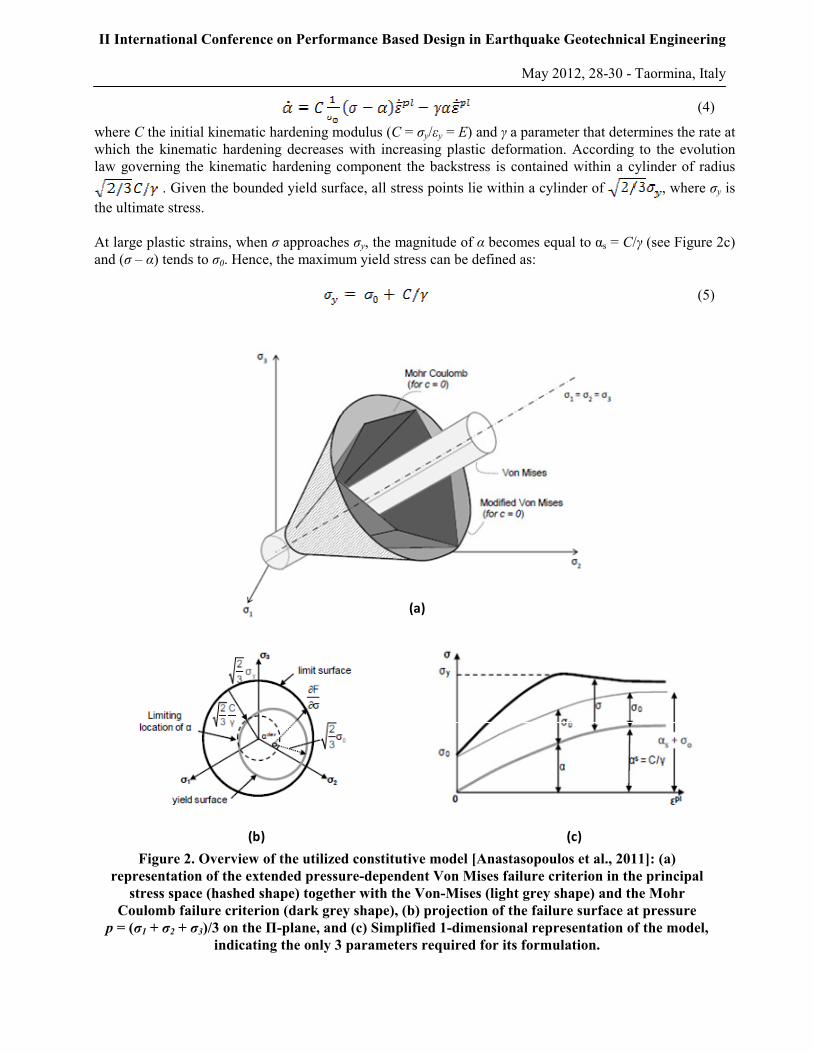
Anastasopoulos et al. [2011] have developed a simplified constitutive model which is based on the Von Mises failure criterion, modified however appropriately so as to model the pressure-dependent behavior of sands as well as that of clays. The Von Mises failure criterion is combined with non-linear kinematic hardening, as illustrated in the graphs of Figure 2, and associated plastic flow rule. The evolution of stresses is defined as: (1) where σ0 corresponds to the stress at zero plastic strain, and α is the "backstress", which determines the kinematic evolution of the yield surface in the stress space according to the relationship: (2) where f(σ – α) is the equivalent Mises stress with respect to the backstress α. An associated flow rule is assumed and the plastic flow rate is:
(3)
where is the equivalent plastic strain rate. The evolution law of the model consists of two components: a non-linear kinematic hardening component and an isotropic hardening component. The kinematic hardening component is defined as an additive combination of a purely kinematic term and a relaxation term, which introduces the non-linearity. The evolution of the kinematic component of the yield stress is described as follows:
II International Conference on Performance Based Design in Earthquake Geotechnical Engineering
May 2012, 28-30 - Taormina, Italy
(4)
where C the initial kinematic hardening modulus (C = σy/εy = E) and γ a parameter that determines the rate at which the kinematic hardening decreases with increasing plastic deformation. According to the evolution law governing the kinematic hardening component the backstress is contained within a cylinder of radius
. Given the bounded yield surface, all stress points lie within a cylinder of , where σy is the ultimate stress. At large plastic strains, when σ approaches σy, the magnitude of α becomes equal to αs = C/γ (see Figure 2c) and (σ – α) tends to σ0. Hence, the maximum yield stress can be defined as: (5)
(a)
(b) (c)
Figure 2. Overview of the utilized constitutive model [Anastasopoulos et al., 2011]: (a)
representation of the extended pressure-dependent Von Mises failure criterion in the principal
stress space (hashed shape) together with the Von-Mises (light grey shape) and the Mohr
Coulomb failure criterion (dark grey shape), (b) projection of the failure surface at pressure
p = (σ1 + σ2 + σ3)/3 on the Π-plane, and (c) Simplified 1-dimensional representation of the model,
indicating the only 3 parameters required for its formulation.

II International Conference on Performance Based Design in Earthquake Geotechnical Engineering
May 2012, 28-30 - Taormina, Italy
For the case of clays, the undrained strength of which is pressure independent, the ultimate stress can be defined as √3Su and hence parameter γ can be calculated as:
(6)
In the case of sands however, shear strength depends also on confining pressure apart from the soil strength characteristics (i.e. the friction angle φ). This pressure-dependency is incorporated in the model by defining the yield stress at saturation as a function of octahedral stress and the friction angle, as follows :
(7)
Accordingly, parameter γ may be calculated as:
(8)
Regarding the other two parameters of the model, σ0 may be defined as a fraction of σy (σ0= λ σy, with λ typically ranging from 0.1 to 0.3) whilst C may be determined with reference to empirical relationships or direct measurements of the small strain Young's modulus.
VALIDATION AGAINST LARGE SCALE EXPERIMENTS
U.C. Davis centrifuge testing of shallow footings on clay
Results from a series of centrifuge tests conducted at UC Davis studying the rocking response of shallow foundations on clay are utilized for the validation of the original constitutive model which applies to clays. A variety of tests were performed, involving both vertical and lateral loading, and reported by Gajan et al., [2005]. Yet, due to space limitations the emphasis here is placed on the response during cyclic lateral pushover tests aiming to focus on the mechanisms of foundation rocking. Figure 3a displays the centrifuge testing model and set-up with instrumentation for the cyclic lateral push tests. Numerical simulations of these tests were performed utilizing the 3-D FE model depicted in Figure 3b. Details on the FE model geometry, properties and discretisation have been documented in Anastasopoulos et al., [2011] along with a comprehensive presentation of results. Comparisons of the foundation response between experiments and analysis are shown in Figures 3c and 3d in terms of moment–rotation and settlement–rotation loops respectively. Some uplifting can be traced in the numerically computed moment-rotation loop especially during the first cycles of loading (which involve relatively small amplitude displacements), something which is not observed to the same extent in the experiment. The latter is indicative of increased plastic straining of the soil underneath the footing, hence resulting to higher dissipation of energy as elucidated by the area included within the experimental hysteresis loops. Increasing the input displacement magnitude (larger amplitude loading cycles) results in excessive soil plastification which is evident from both the experimental and the numerically computed moment–rotation loops. These hysteresis loops reveal a highly non-linear response of the soil– foundation system. Furthermore, the moment– rotation curve now conspicuously manifests the mobilization of the ultimate capacity (Mult ≈ 300 kNm) : increase of rotation for constant moment. It should be noted that the

II International Conference on Performance Based Design in Earthquake Geotechnical Engineering
May 2012, 28-30 - Taormina, Italy
experimental hysteresis loops systematically reveal a non-symmetric behavior, which is attributed to some localized plastification underneath the footing edges possibly occurring due to earlier cycles of shearing or inhomogeneities in the construction of the physical model, which of course may not be reproduced in the analysis. The numerical prediction is quite successful in terms of the settlement–rotation response (Figure 3d). Excessive uplift appears to take place indicated by the sharp edges of the settlement–rotation loops. As elucidated by Gajan et al. [2005], foundation rocking during large amplitude lateral loading leads to (permanent) loss of contact between the soil and the footing. The generated gap at the uplifted side is associated with a drastic reduction of the effective width of the foundation, leading to extensive soil yielding at the opposite side, further increasing the detached area of the foundation. Overall, it may be claimed that despite some discrepancies, which mainly involve the response under low amplitude displacements, the numerical model reliably reproduces the experiments throughout the entire range of displacements capturing with sufficient accuracy the ultimate lateral capacity of the foundation as well as the progressively non-linear response in the moment–rotation plane, implied by the degradation of rotational stiffness with increasing rotation amplitude. Furthermore the analysis predicts the accumulation of permanent settlement underneath the footing and the predomination of uplifting with increasing the number of loading cycles.
Horizontal
Linear
Potentiometers
Rigid floor
Strip footing
506.9
228.0
B
127.0
y
z
LBay Mud
Actuator
277.0
(a) Centrifuge testing set-up: Horizontal cyclic push (b) Centrifuge testing set-up: Horizontal cyclic push
Se
ttle
me
nt
(mm
)
3-D continuum elements
Interface elements
Beam elements
-160
-120
-80
-40
0
-0.1 -0.05 0 0.05 0.1
experiment
analysis
(c) Experimental vs. analytical moment–rotation loops (d) Experimental vs. analytical settlement–rotation loops
Mo
me
nt
(kN
m)
-400
-200
0
200
400
-0.1 -0.05 0 0.05 0.1
experiment
analysis
Rotation (rad) Rotation (rad)
Figure 3. Model validation against UC Davis Centrifuge Tests on clay.

II International Conference on Performance Based Design in Earthquake Geotechnical Engineering
May 2012, 28-30 - Taormina, Italy
Large-scale testing of a square footing on dense and loose sand
Aiming to verify the claim that, after being appropriately modified so as to encompass the pressured dependency of frictional materials (Equations 7 and 8), the presented numerical model may as well apply to sands, a series of large scale 1-g tests performed on footings upon sandy soil profiles are simulated and results are summarized in Figure 4 for both dense and loose sand specimens. The experiments were conducted at the ELSA facility in ISPRA (Italy) in the framework of the TRISEE research project and have been documented by Faccioli et al., [1999]. In detail report of their numerical simulations has been conducted by Anastasopoulos et al., [2011]. A remarkable agreement is observed between measured and calculated hysteresis loops produced during slow cyclic tests on dense sand (Figure 4a). Both loops evolve quite symmetrically. The numerical analysis effectively reproduces the lateral capacity of the system : Mult ≈ 100 kNm. Furthermore, it captures with sufficient accuracy both the initial stiffness of the system, and the gradual degradation of rotational stiffness with increasing rotation. Contrarily to the uplifting behavior of the footing on dense sand (evident by the S-shaped loops of Figure 4a), the foundation on loose sand is obviously subjected to substantial irrecoverable sinking within the soil. This is justified by both the numerical model and the experimental results, which show clearly larger energy dissipation. The analysis has been successful in simulating the experimentally observed mobilization of the foundation capacity. In very good accord with the measured value, the predicted ultimate moment of the system is Mult ≈ 40 kNm in the negative loading direction. It should be noted that the asymmetry of response in the test, attributable to some irregularity in the input displacement, cannot be reproduced in the analysis. Yet, the general comparison between analytical and experimental results is judged as very satisfactory.
DEALING WITH SCALE EFFECTS: SIMULATION OF 1-G REDUCED SCALE TESTS
It is well known that the strength of sands highly depends on the applied stress [Bolton, 1986]. Thus, physical modeling in reduced scale results in misreproduction of the soil strength due to the underestimation of the distribution and evolution of the applied effective stress field, this being admittedly the most important shortcoming of 1–g testing against centrifuge modeling. When performing numerical simulations of reduced-scale experiments on sand, it is essential to account for such scale related variations in the soil strength profile. This may be achieved simply by inputting a pressure dependent relationship for the soil friction angle, which may be determined with reference to shearbox test results, instead of a constant value of φ (Figure 5a). The scale factor N is unavoidably introduced in the calculation of the apparent φ, so as to achieve stress–strength similarity for any pair of homologous points between the model and the prototype (Figure 5b). Hence, reduced scale effects may be incorporated in the herein presented constitutive model by modification of Equation (7), so as any soil element in the FE model (in prototype scale) to have the same strength with its homologous point in the physical model (model scale):
(9)

II International Conference on Performance Based Design in Earthquake Geotechnical Engineering
May 2012, 28-30 - Taormina, Italy
A series of small scale experiments on foundations of various sizes and safety factors, conducted at the Laboratory of Soil Mechanics of NTUA and documented in a companion paper (Drosos et al., 2011), were simulated numerically in order to verify the ability of the presented numerical method in capturing scale effects. The experimental campaign involved three rigid 1-dof systems supported upon a layer of dense sand through three distinctively different shallow foundations: (i) the so called large foundation (FSV = 7.3) was designed in accord with current capacity design practice; (ii) the medium foundation (FSV = 3.5) was unconventionally designed to allow uplifting and yielding mechanisms to take place; and (iii) the small foundation (FSV = 2.1) represents a seriously under-designed foundation.
Air cushions
Reaction Beam
1 m
3 m
Ticino Sand
0.9 m
Interface
Elements
Beam elements
-150
-100
-50
0
50
100
150
-0.03 -0.02 -0.01 0 0.01 0.02 0.03
experiment
150
100
50
0
50
100
150
-0.03 -0.02 -0.01 0 0.01 0.02 0.03
analysis
(a)
-60
-40
-20
0
20
40
60
-0.04 -0.02 0 0.02 0.04
60
40
20
0
20
40
60
-0.04 -0.02 0 0.02 0.04
(b)
Mo
me
nt
(kN
m)
Rotation (rad)
Mo
me
nt
(kN
m)
Rotation (rad)
experiment analysis
Figure 4. Model validation against 1-g large scale tests on sand. Comparison of cyclic response
in terms of foundation moment - rotation loops for . (a) dense sand; and (b) loose sand.

II International Conference on Performance Based Design in Earthquake Geotechnical Engineering
May 2012, 28-30 - Taormina, Italy
z
Nz
Homologous
Points
Model Scale
Prototype Scale
(b)
σv
Nσv
φ
σv
φ = Α – Β ln(σv)
PrototypeModel
1/N
(a) Figure 5. Effect of reduced scale modeling on the reproduction of the prototype soil strength
distribution: (a) friction angle is a function of effective stress; (b) for any pair of homologous
points between prototype and scaled down model, the vertical stress in the model is N times
lower than in the prototype and therefore the effective friction angle is somewhat larger.
Monotonic Loading
Figure 6 compares the numerically computed against the measured response of the three foundations to monotonic horizontal pushover loading in terms of moment–rotation and settlement– rotation curves. Naturally, moment capacity appears as a decreasing function of the foundation size. Furthermore, in accord with the design, the lightly loaded large foundation demonstrates an uplift dominated response and, as shown by the corresponding settlement–rotation curve, its centre appears to move upwards straight after the application of loading revealing that more than half of the foundation area looses contact with the supporting soil. The opposite appears to be the case for the two smaller foundations, where the behavior is mostly associated with soil yielding owing to the relatively lower bearing capacity. Hence, the centre of the medium and the small foundations move downwards (settle) with increasing displacement at a rate which presumably increases with reducing FSV. The numerical method predicts with sufficient accuracy the rocking stiffness (gradient of the M–θ curve) and reproduces generally well the moment–rotation response of all three foundations despite the slight underestimation of the ultimate moment capacity for the two larger ones. Equally satisfactory in general terms is the comparison between numerically predicted and measured response in the settlement–rotation plane. Some discrepancies refer to the numerical prediction of the soil–foundation system stiffness, indicated by the gradient of the w–θ curve, which is somewhat underestimated in the case of the large foundation and contrarily somewhat over-predicted in the case of the small one. Nevertheless, the numerical method appears to reproduce the general attributes of response to this type of loading with sufficient reliability. Cyclic Loading
The three structure–foundation systems were also subjected to cyclic pushover tests. The loading sequence included a series of displacement cycles of increasing amplitude divided for convenience into three loading packets. Figure 7 compares the experimental results with the results of the respective numerical simulations in terms of M–θ and w–θ loops for all three foundations during the third loading packet, which involved large amplitude displacements (generally ranging from 10 to 50 cm in prototype scale).

II International Conference on Performance Based Design in Earthquake Geotechnical Engineering
May 2012, 28-30 - Taormina, Italy
0-0.02 0.02 0-0.02 0.02
0-0.02 0.02 0-0.02 0.02
Series1Experimental Numerical Results
4
2
-2
-4
-6
0-0.02 0.02
4
2
-2
-4
-6
4
2
-2
-4
-6
0-0.02 0.02
80
40
-40
-80
80
40
-40
-80
80
40
-40
-80
0246810
Plastic Strain (%)
Large
FSv = 7.3
Medium
FSv = 3.5
Small
FSv = 2.1M
om
en
t (M
Nm
)
Rotation (rad)
Se
ttle
me
nt
(cm
)
Rotation (rad) Rotation (rad)
Figure 6. Model validation against 1-g reduced scale tests (N = 20). Monotonic horizontal
pushover tests results in terms of moment–rotation and settlement–rotation curves compared
with the FE analysis results for the three different foundation sizes: the large (FSV = 7.3); the
medium (FSV = 3.5) and the small foundation (FSV = 2.1).
As expected, non-linear material response, betrayed by the area enclosed in the moment–rotation loop becomes more significant with decreasing the foundation size. Thus, uplifting dominates the response of the lightly loaded large foundation (observe the impressive 2 cm lift-off of its center during the last loading cycle in Figure 7a), yet giving place to soil yielding mechanisms as FSV reduces. Some uplifting, although

II International Conference on Performance Based Design in Earthquake Geotechnical Engineering
May 2012, 28-30 - Taormina, Italy
much less than in the case of the large foundation, may be traced in the settlement–rotation response of the medium foundation (Figure 7b) while the small foundation demonstrates pure "sinking" response, implied by the downwards movement of its center on every half-cycle of loading. Comparison between analytical and experimental results manifests the effectiveness of the numerical method in capturing the details of rocking response, namely the ultimate lateral capacity, the degradation of stiffness with increasing rotation and the interchange between uplift and yielding mechanisms as well as their relation to the relative weight (i.e. FSV). Interestingly, the agreement between analysis and experiment becomes surprisingly good in the case of the small foundation when material non-linearity is significant. Furthermore, the numerical method gives excellent predictions of the total accumulation of settlements under the foundations as well as the rate of settlement per cycle. However, it should be mentioned that the comparison was less satisfactory for the two previous loading packets (which are not shown here), where the three systems were subjected to smaller displacements, partly because of the simplicity of the constitutive model and also due to the inaccuracies associated with reduced scale testing in the small strain domain.
-80
-60
-40
-20
0
20
40
60
80
-0.015 -0.005 0.005 0.015
-40
-30
-20
-10
0
10
20
30
40
-0.02 -0.01 0 0.01 0.02
-40
-30
-20
-10
0
10
20
30
40
-0.03 -0.02 -0.01 0 0.01 0.02 0.03
Mo
me
nt
(MN
m)
Large
FSv = 7.3
Medium
FSv = 3.5
Small
FSv = 2.1
Series1 Series5Experimental Numerical Results
0
2
4
6
-0.015 -0.005 0.005 0.015
0
5
10
15
-0.02 -0.01 0 0.01 0.02
0
2
4
6
8
10
12
14
16
-0.03 -0.02 -0.01 0 0.01 0.02 0.03
Rotation (rad)
Se
ttle
me
nt
(cm
)
Rotation (rad) Rotation (rad)
(a) (b) (c)
Figure 7. Model validation against 1-g reduced scale tests (N = 20). Cyclic horizontal pushover
tests results in terms of moment–rotation and settlement–rotation curves and comparison with
the FE analysis results for the three different foundation sizes considered: the large (FSV = 7.3);
the medium (FSV = 3.5) and the small foundation (FSV = 2.1).

II International Conference on Performance Based Design in Earthquake Geotechnical Engineering
May 2012, 28-30 - Taormina, Italy
CONCLUSIONS
The paper has presented a comprehensive validation of the simplified constitutive model of Anastasopoulos et al., [2011] with regard to the non-linear rocking response of shallow foundations. Employed in the simulation of different large scale experiments conducted on clayey and sandy soil profiles, as well as in the simulation of small scale experiments on sand, the presented numerical methodology proved capable of reliably reproducing all the different aspects of shallow foundation rocking response regardless of the supporting soil material or the possible effect of physical modeling scale. More specifically, the most important conclusions may be summarized as follows: a) The Von Mises failure criterion of the constitutive model can be considered appropriate for clay under
undrained conditions. b) The extended normal-pressure-dependent Von Mises failure criterion, employed to render the model
applicable to sand, constitutes a simplified approximation of real sand behavior. c) Despite its inherent simplifications and as far as the problem of rocking of a shallow foundation is
considered, the proposed numerical model has been shown to yield quite satisfactory results for both clayey and sandy soils. Through the validation presented herein, the model was found capable of capturing with reasonable engineering accuracy the details (ultimate capacity, stiffness degradation with increasing rotation, hysteretic response, settlement–uplifting in relation to the rotation amplitude and the number of loading cycles) of such a complex problem where multiple types of non-linearity are combined.
d) Furthermore, the numerical method was appropriately modified so as to account for scale effects when reproducing reduced scale experiments and confidence on its validity was strengthened by successful simulations of a series of small-scale experiments on the monotonic and cyclic non-linear response of footings of varying safety factors.
e) Being easily implemented in commercial FE codes and requiring but only the knowledge of soil strength (Su for clays and φ for sand) and small-strain stiffness (Go or Vs ) the model is believed to provide a practically applicable solution, not restricted to simple superstructures, and not to be solely used by numerical analysis specialists.
ACKNOWLEDGEMENT
The research presented in this paper was funded by the European Research Council (ERC) Program “IDEAS, Support for Frontier Research – Advanced Grant", under Contract number ERC–2008–AdG 228254–DARE.
REFERENCES
Anastasopoulos I., Gazetas G., Loli M., Apostolou M, Gerolymos N. (2010), Soil Failure can be used for
Earthquake Protection of Structures, Bulletin of Earthquake Engineering, Vol. 8(2), pp. 309–326. Anastasopoulos I., Gelagoti F., Kourkoulis R., Gazetas G. (2011), Simplified Constitutive model for
Simulation of Cyclic Response of Shallow Foundations: Validation against Laboratory Tests, Journal of Geotechnical and Geoenvironmental Engineering, ASCE (in press).
Chatzigogos C.T., Pecker A., Salencon J. (2009), Macroelement modeling of shallow foundations, Soil Dynamics and Earthquake Engineering, Vol. 29(6), pp. 765–781.
Dafalias Y.F., & Manzari M.T. (2004), Simple plasticity sand model accounting for fabric change effects. ASCE Journal of Engineering Mechanics, 130(6), pp. 622–34.

II International Conference on Performance Based Design in Earthquake Geotechnical Engineering
May 2012, 28-30 - Taormina, Italy
Drosos V., Georgarakos T., Loli M., Anastasopoulos I., and Gazetas G. (2011), Non-linear Soil–Foundation Interaction : An Experimental Study on Sand, Proceedings of the 4th Japan–Greece Workshop, Kobe, October 2011.
Faccioli E., Paolucci R., and Vanini M., eds (1999), TRISEE : 3D Site Effects and Soil-Foundation Interaction in Earthquake and Vibration Risk Evaluation, European Commission Publications.
Gajan S., Kutter B.L., Phalen J.D., Hutchinson T.C., Martin G.R. (2005), Centrifuge modeling of load-deformation behavior of rocking shallow foundations, Soil Dynamics and Earthquake Engineering, 25, pp. 773–783.
Gajan S. & Kutter B.L. (2009), "Contact interface model for shallow foundations subjected to combined loading", Journal of Geotechnical and Geoenvironmental Engineering, ASCE, 135(3), pp. 407–419.
Gazetas G., Anastasopoulos I., Apostolou M. (2007), Shallow and Deep Foundations under Fault Rupture or Strong Seismic Shaking, Earthquake Geotechnical Engineering, Pitilakis K., Editor, Springer : Berlin, pp. 185–210.
Harden C., Hutchinson T., and Moore M. (2006), Investigation into the effects of foundation uplift on simplified seismic design procedures, Earthquake Spectra, 22(3), pp. 663–692.
Houlsby G.T. & Puzrin A.M. (2006), Principles of Hyperplasticity, Springer : Berlin. Martin G. R. & Lam I. P. (2000), “Earthquake Resistant Design of Foundations : Retrofit of Existing
Foundations”, Proceedings of GeoEng 2000 Conference, Melbourne, pp. 19–24.