nonlinear multi-scale modeling of reinforced plastic parts ... · digimat to radioss improves...
TRANSCRIPT

www.e-Xstream.com
Nonlinear Multi-Scale Modeling of Reinforced Plastic Parts with
DIGIMAT to RADIOSS.e-Xstream engineering
Th. Malo, R. Ramaya, L. Adam, Th. Villette, R. Assaker
[email protected]+32 495 52 56 52

OutlineOutline
Introduction
e-Xstream engineering
Motivation
Digimat to RADIOSS: Nonlinear Multi-Scale Modeling
1. Predict Fiber Orientation
2. Map fiber orientation from Injection Molding Mesh to Radioss Mesh
3. Setup the DIGIMAT material Model
4. Run the Digimat to RADIOSS Analyses
5. Post Process the (Accurate) Results!
ConclusionsTuesday, November 10, 2009 Copyright© e-Xstream engineering, 2009 2

IntroductionIntroduction
The use of composites like reinforced plastics continues to increase in Automotive, Aerospace, ...One of the main drivers for using composites is:ü High stiffness/weight ratio Lighter Greener
The two main barriers to using composites are:1. Technical: Relative low “familiarity” with the material and
suboptimal design & simulation tools2. Economical: Is the composite part cheaper that its metallic
equivalent ?
Predictive Simulation Tools can make the difference
e-Xstream’s Value Proposition
ee--Xstream engineeringXstream engineering
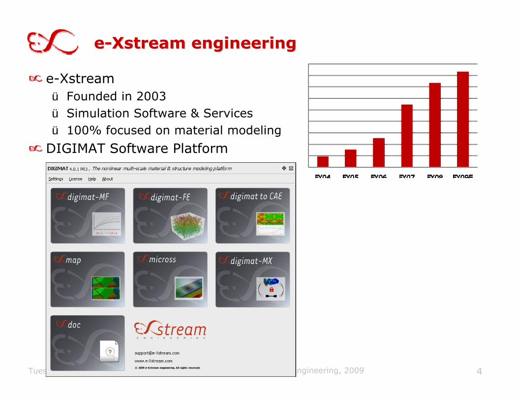
e-Xstreamü Founded in 2003ü Simulation Software & Servicesü 100% focused on material modeling
DIGIMAT Software Platform
Tuesday, November 10, 2009 Copyright© e-Xstream engineering, 2009 4

Target Materials & IndustriesTarget Materials & IndustriesTarget (Mutli-Phase) Materials :
ü Reinforced Plasticsü Rubber: Carbon or Silica Filledü Woven & Non-Woven Composites (CFRP,…)ü Nano-Composites: Nano Clays, Carbon Nano Tubes,…ü Hard Metals: CoWCü Carbonü …
Target Industriesü Material Suppliers: Plastics, Rubber, Carbon,…
ü Automotive: OEMs & Suppliers, Tires, …
ü Aerospace: Airplanes composite structures, Satelites, Launchers,…
ü Electronic & Electric Products: Mobile phones, Electric connectors,…
ü Industrial Goods: Cutting tools, furnaces, Generators, Transformes,…
ü Sports & Leisure, …

Objective: To predict the local & global behavior of a reinforced plastic part subject to a “3-Point Bending Impact”
Material: PAGF30PA630% short glass fibers
6
MotivationMotivation
11/10/2009 Copyright© e-Xstream engineering, 2003-2009
Courtesy of Rhodia
Vz= 5m/s

Local, Anisotropic, Nonlinear, StrainLocal, Anisotropic, Nonlinear, Strain--Rate Rate Dependent Material BehaviorDependent Material Behavior
Tuesday, November 10, 2009 Copyright© e-Xstream engineering, 2009 7
RADIOSS FEA of Reinforced Plastic PartsRADIOSS FEA of Reinforced Plastic Parts
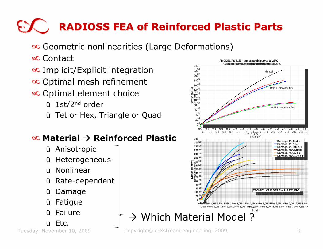
Geometric nonlinearities (Large Deformations)ContactImplicit/Explicit integrationOptimal mesh refinementOptimal element choiceü 1st/2nd order ü Tet or Hex, Triangle or Quad
Material Reinforced Plasticü Anisotropicü Heterogeneousü Nonlinearü Rate-dependentü Damageü Fatigueü Failureü Etc.
Tuesday, November 10, 2009 Copyright© e-Xstream engineering, 2009 8
Which Material Model ?
AMODEL AS-4133 - stress-strain curves at 23°C dumbell specimen and test samples from mold II
0
20
40
60
80
100
120
140
160
180
200
220
240
0.0 0.2 0.4 0.6 0.8 1.0 1.2 1.4 1.6 1.8 2.0 2.2 2.4 2.6 2.8 3.0strain (%)
stre
ss (M
Pa)
dumbell
Mold II - along the flow
Mold II - across the flow
AMODEL AS-4133 - stress-strain curves at 23°C dumbell specimen and test samples from mold II
0
20
40
60
80
100
120
140
160
180
200
220
240
0.0 0.2 0.4 0.6 0.8 1.0 1.2 1.4 1.6 1.8 2.0 2.2 2.4 2.6 2.8 3.0strain (%)
stre
ss (M
Pa)
dumbell
Mold II - along the flow
Mold II - across the flow
020406080
100120140160180200220240260280300320
0,0% 0,5% 1,0% 1,5% 2,0% 2,5% 3,0% 3,5% 4,0% 4,5% 5,0% 5,5% 6,0% 6,5% 7,0% 7,5% 8,0Strain
Stre
ss (N
/mm
²)
Damage, 0°, StaticDamage, 0°, 1 s-1Damage, 0°, 100 s-1Damage, 45°, StaticDamage, 45°, 1 s-1Damage, 45°, 100 s-1
TECHNYL C218 V35 Black, 23°C, Eh0
020406080
100120140160180200220240260280300320
0,0% 0,5% 1,0% 1,5% 2,0% 2,5% 3,0% 3,5% 4,0% 4,5% 5,0% 5,5% 6,0% 6,5% 7,0% 7,5% 8,0%Strain
Stre
ss (N
/mm
²)
Damage, 0°, StaticDamage, 0°, 1 s-1Damage, 0°, 100 s-1Damage, 45°, StaticDamage, 45°, 1 s-1Damage, 45°, 100 s-1
TECHNYL C218 V35 Black, 23°C, Eh0

Nonlinear MultiNonlinear Multi--Scale Modeling ProcessScale Modeling Process
Tuesday, November 10, 2009 Copyright© e-Xstream engineering, 2009 9
Fiber Length Distribution
0
10
20
30
40
50
60
70
80
90
100
25 75 125
175
225
275
325
375
425
475
525
575
625
675
725
775
825
875
925
975
1025
1075
1125
Length [µm]
Num
ber
Phase Material & Composite Microstructure-Fiber Shape
-Fiber Weight Fraction
-Fiber Length Distribution
Fiber Orientations
Material DesignProcess Design
RADIOSS
Structure Design
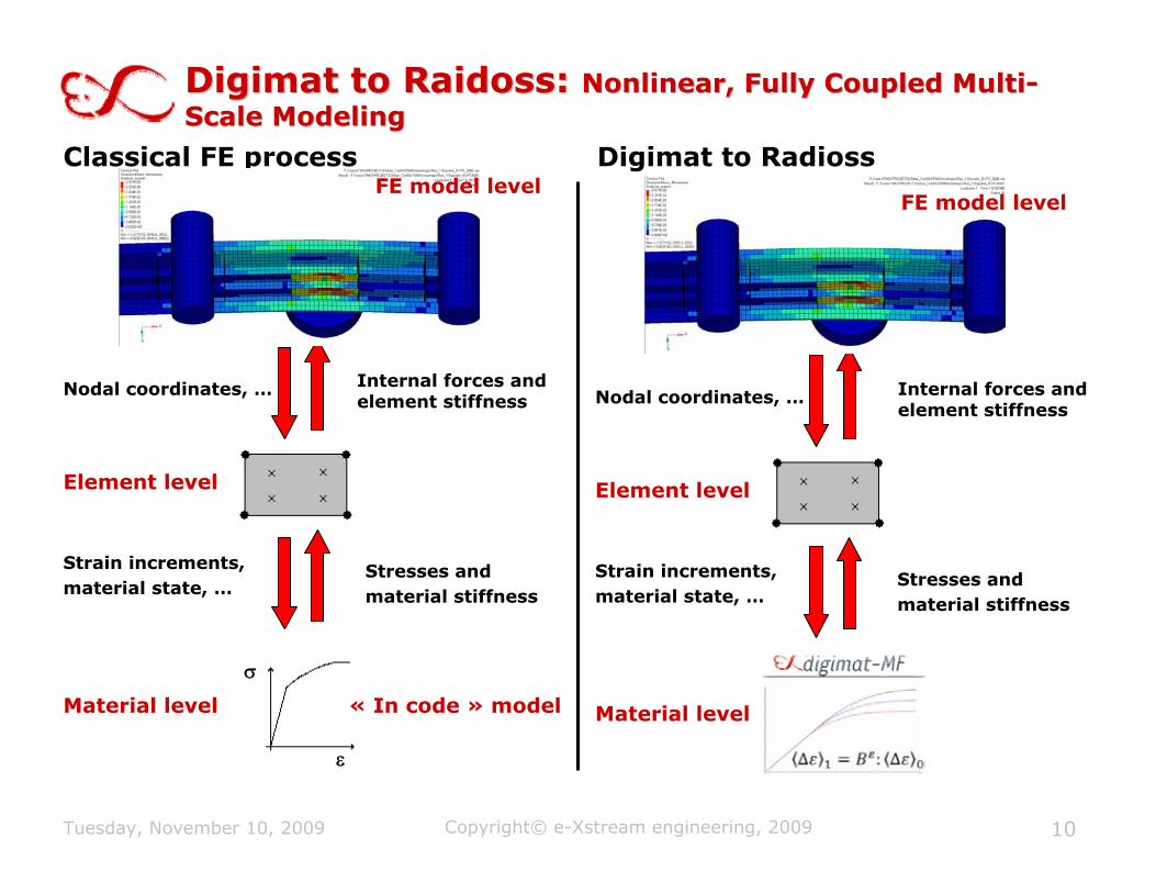
Digimat to Raidoss: Digimat to Raidoss: Nonlinear, Fully Coupled MultiNonlinear, Fully Coupled Multi--Scale ModelingScale Modeling
Tuesday, November 10, 2009 Copyright© e-Xstream engineering, 2009 10
Nodal coordinates, …
Strain increments,material state, …
Element level
Material level
Stresses and material stiffness
Internal forces and element stiffness
ε
σ
Classical FE process Digimat to Radioss
« In code » model
Nodal coordinates, …
Strain increments,material state, …
Element level
Stresses and material stiffness
Internal forces and element stiffness
Material level
FE model levelFE model level

MF & FEMF & FE--based Micromechanicsbased Micromechanics
Pros
Fast model preparation/solution
Accurate predictions
Enables fully coupled nonlinear multi-scale Analyses
Cons
Ellipsoidal inclusions
Uniformly distributed inclusions
Average per phase (micro) results
Pros
Accurate predictions at the micro scale
Complex inclusion shapes (non ellipsoidal)
Explicit modeling of clustering & percolation
Cons
Relatively Complex RVE generation
Large RVE models (CPU intensive FEA)
Uncoupled multi-scale analyses
Requires mesh optimization
E Σ
Local phase behavior
Global behavior
Localization Averaging
εr σr
EHx rrr Δ=Δ=Δ :)(εε
rrr c εσ Δ=Δ :
εσ Δ=Δ :)( rcc
Tuesday, November 10, 2009 11Copyright© e-Xstream engineering, 2009

MultiMulti--Scale Modeling Analysis Work FlowScale Modeling Analysis Work Flow
Tuesday, November 10, 2009 Copyright© e-Xstream engineering, 2009 12
Matrix PropertiesReinforcement PropertiesComposite Morphology
Fiber Length/diameterFiber Weight/Volume Fraction
Composite Properties
RadiossMesh
Fiber Orientation
InjectionMesh
InjectionMat Prop.
InjectionProcess Param.
Fiber
OrientationResidualStresses
ResidualTemperature
Micro/macro FEA results
MoldflowMoldex3DSigmasoft
REM3D3DTimon
RADIOSS
1
2
3
4
5

Injection Molding Simulation: Fiber Injection Molding Simulation: Fiber OrientationOrientation
Tuesday, November 10, 2009 Copyright© e-Xstream engineering, 2009 13
Mold Filling
Fiber Orientation

Injection Molding & Structural FEA MeshInjection Molding & Structural FEA Mesh
Tuesday, November 10, 2009 Copyright© e-Xstream engineering, 2009 14
Moldflow Mesh6, 438 Triangles20 Layers
RADIOSS Mesh4, 697 Quads10 Layers

Mapping of Fiber OrientationMapping of Fiber Orientation
Tuesday, November 10, 2009 Copyright© e-Xstream engineering, 2009 15
Map

Mapping of Fiber Orientation: Quality CheckMapping of Fiber Orientation: Quality Check
Tuesday, November 10, 2009 Copyright© e-Xstream engineering, 2009 16
Skin (Layer 2) Core (Layer 6)

Material DataMaterial Data
The use of DIGIMAT requires:Material data
for each phase of the composite
Micro-structure dataConstituentsMorphology
Two Methods to get these dataü Direct Approach From Measured Polymer Matrix Behaviorü Reverse Approach From Measured Composite Behavior
Copyright e-Xstream engineering 2009

Micormechanics Micormechanics –– DirectDirect ApproachApproachInputü Microstructure Constituents for the Reinforced Material (e.g. PAGF30)
• Matrix Phase (e.g. PA)• Reinforcement Phase(s) (e.g. GF)
ü Material behavior of each Phase:• PA: Elasto-Plastic (E, ν, σy, …)• GF: Elastic (E, ν)
ü Reinforced Material Morphology• Fiber Content (e.g. 30%)• Fiber Orientation (e.g. Orientation Tensor for each element)• Fiber Length (e.g. AR=L/D~25)
Output ü Stress-Strain Response of the Reinforced Material (PAGF30)(for each orientation/element)
Prosü Fully Predictive
Consü Availability of accurate phase dataü Hypotheses of the Mean Field Method
Tuesday, November 10, 2009 Copyright© e-Xstream engineering, 2009 18

Micormechanics Micormechanics –– ReverseReverse ApproachApproachInputü Microstructure Constituents for the Reinforced Material (e.g. PAGF30)
• Matrix Phase (e.g. PA)• Reinforcement Phase(s) (e.g. GF)
ü Material behavior:• Stress-Strain Curve(s) of the Reinforced Material (e.g. PAGF30)• GF: Elastic (E, ν)
ü Reinforced Material Morphology• Fiber Content (e.g. 30%)• Fiber Orientation (e.g. Aij=(0.8,0.2, 0,..)• Fiber Length (e.g. AR=L/D~20)
Output • Material behavior of Matrix Phase (e.g. PA as Elasto-Plastic (E, ν, σy, …))
Prosü Find missing material dataü Compensates for numerical hypotheses
Consü Depends on the numerical algorithms
Tuesday, November 10, 2009 Copyright© e-Xstream engineering, 2009 19

Reverse engineering has been done using 2 dumbbells:
ü 1 aligned with the flow directionü 1 transverse to the flow
Multilayer Micro-Structure :ü Describe skin/core effects through the
thicknessü Better describes the composite when
reverse-engineering the material model
DigimatDigimat--MF : MF : Building the material lawBuilding the material law
Courtesy of Rhodia
2011/10/2009 Copyright© e-Xstream engineering SA, 2003-2009
90° 45°
0°
Injection plate
Flow direction
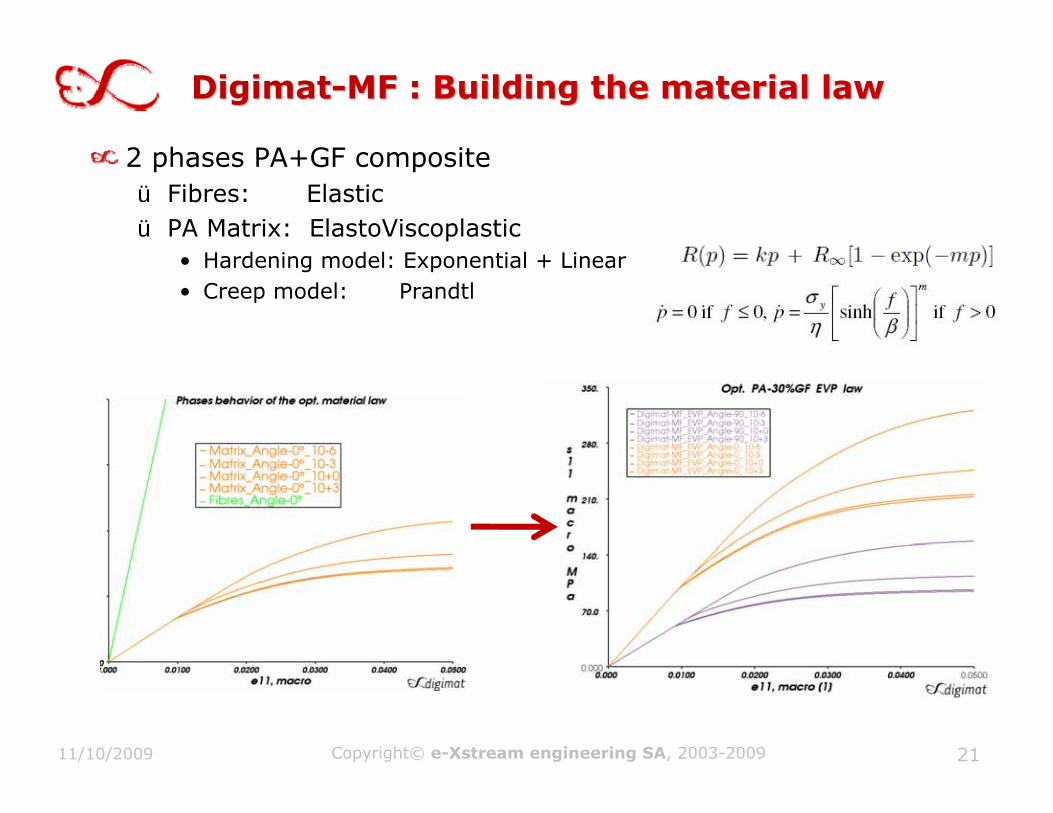
DigimatDigimat--MF : MF : Building the material lawBuilding the material law
2 phases PA+GF compositeü Fibres: Elasticü PA Matrix: ElastoViscoplastic
• Hardening model: Exponential + Linear• Creep model: Prandtl
2111/10/2009 Copyright© e-Xstream engineering SA, 2003-2009

Reverse Engineering of PA fromReverse Engineering of PA from PAGF30 PAGF30
Copyright© e-Xstream engineering, 2009Tuesday, November 10, 2009 22
Matrix phase: PA
Behavior: J2-plasticityexponential + linear hardeningDensity = 1.14 E-06 kg/mm3
Young modulus = 3400 MpaPoisson coefficient = 0.4Yield stress = 35 MPaHardening modulus= 21 MPaHardening exponent= 140Hardening modulus2= 50 MPa
Isotropic method = Spectral
Creep model = PrandtlCreep coefficient = 30 MPaHardening exponent= 3Creep coefficient2= 15 MPa
Inclusion phase: Glass FibersBehavior: Elastic
Density = 2.54 E-06 kg/mm3
Poisson coefficient = 0.22Young modulus = 72000 MPaAR = 23.5

Failure ModelFailure Model
Failure model applied at 3 scalesü Micro (or Phase) Scale PA matrix and/or Fiber Reinforcementü “Pseudo-Grain” Scale “UD” PAGFü Macro (or Composite) Scale PAGF
Failure Modelsü Max stressü Max strainü Tsai-Hillü …
Failure Modelü FPGF
• E11 max = 0.028• E22 max = 0.052
Tuesday, November 10, 2009 Copyright© e-Xstream engineering, 2009 23

Isotropic Isotropic Johnson Cooke Model Isotropic Isotropic Johnson Cooke Model
Tuesday, November 10, 2009 Copyright© e-Xstream engineering, 2009 24
E 10000 MPav 0.37a 100 MPab 500 MPan 0.4
eps max 0.025

Digimat to Radioss: Digimat to Radioss: Local/ Anisotropic/StrainLocal/ Anisotropic/Strain--Rate/Pseudo Grain FailureRate/Pseudo Grain Failure
Tuesday, November 10, 2009 Copyright© e-Xstream engineering, 2009 25
ConclusionsConclusions
Nonlinear Mean Field homogenization techniques enable an accurate prediction of the global (macroscopic) response of reinforced plastics based on:
ü The behavior of each phase: polymer & reinforcementsü The microstructure defined by the
• Fiber content: 30%, 40%...• Fiber length: short/long/distribution of length• Fiber orientation: measured (e.g. Micro Tomography) or Precited (e.g. Injection
Molding) Locally
The material response of the (in-situ) polymer matrix is not always available. Reverse Engineering is an attractive method to:
ü Generate Missing Dataü Compensate for some numerical approximations
Digimat to RADIOSS improves considerably the accuracy of the FEAof Reinforced Plastic Parts thanks to an accurate modeling of the local nonlinear anisotropic and strain-rate dependent response of the fiber reinforced plastic material.
Tuesday, November 10, 2009 Copyright© e-Xstream engineering, 2009 26