nonlinear mechanics of mems rectangular microplates...
TRANSCRIPT

Nonlinear Mechanics of MEMS Rectangular
Microplates under Electrostatic Actuation
Dissertation by
Shahid Saghir
In Partial Fulfillment of the Requirements
For the Degree of
Doctor of Philosophy
King Abdullah University of Science and Technology, Thuwal,
Kingdom of Saudi Arabia
Copyright © December, 2016
Shahid Saghir
All Rights Reserved

2
The dissertation of Shahid Saghir is approved by the examination committee
Examination Committee Approval
Committee Member: Prof. Stefano Lenci
Committee Member: Prof. Taous Meriem Laleg
Committee Member: Prof. Mohammad I. Younis
Committee Chairperson: Prof. Sigurdur Thoroddsen

3
ABSTRACT
Nonlinear Mechanics of MEMS Rectangular Microplates under
Electrostatic Actuation
Shahid Saghir
The first objective of the dissertation is to develop a suitable reduced order model capable
of investigating the nonlinear mechanical behavior of von-Karman plates under
electrostatic actuation. The second objective is to investigate the nonlinear static and
dynamic behavior of rectangular microplates under small and large actuating forces.
In the first part, we present and compare various approaches to develop reduced order
models for the nonlinear von-Karman rectangular microplates actuated by nonlinear
electrostatic forces. The reduced-order models aim to investigate the static and dynamic
behavior of the plate under small and large actuation forces. A fully clamped microplate
is considered. Different types of basis functions are used in conjunction with the Galerkin
method to discretize the governing equations. First we investigate the convergence with
the number of modes retained in the model. Then for validation purpose, a comparison of
the static results is made with the results calculated by a nonlinear finite element model.
The linear eigenvalue problem for the plate under the electrostatic force is solved for a
wide range of voltages up to pull-in.
In the second part, we present an investigation of the static and dynamic behavior of a
fully clamped microplate. We investigate the effect of different non-dimensional design

4
parameters on the static response. The forced-vibration response of the plate is then
investigated when the plate is excited by a harmonic AC load superimposed to a DC load.
The dynamic behavior is examined near the primary and secondary (superharmonic and
subharmonic) resonances. The microplate shows a strong hardening behavior due to the
cubic nonlinearity of midplane stretching. However, the behavior switches to softening as
the DC load is increased. Next, near-square plates are studied to understand the effect of
geometric imperfections of microplates.
In the final part of the dissertation, we investigate the mechanical behavior of initially
curved microplates. Microplates often experience an initial curvature imperfection, due to
the micro fabrication process, which affects significantly their mechanical behavior. In
this case a clamped-free-clamped-free microplate is considered. We validate the reduced
order model by comparing the calculated static behavior and the fundamental natural
frequency with those computed by a finite element model. As case studies, we consider
two commonly encountered profiles of the initial curvature imperfection and study their
effects on both the static and dynamic responses of the microplates.
Next, an initially curved microplate made of silicon nitride is studied. The static
behaviour of the microplate is investigated when applying a DC voltage. Then, the
dynamic behaviour of the microplate is examined under the application of a harmonic AC
voltage, superimposed to a DC voltage. Simulation results calculated by the reduced
order model are compared with experimental data for model validation purpose, which
show good agreement.

5
DEDICATION
To my parents, Hameeda Bibi and Muhammad Shafi (Late)
To my wife Atika and our daughters Shehar, Mehar, and Jannat.

6
ACKNOWLEDGMENTS
I would like to take this opportunity to express my deep gratitude and thanks to King
Abdullah (late), the benefactor, who founded this beacon of hope (KAUST) on the shores
of Red Sea, which has provided me with the best research facilities and conducive
environment to pursue my higher studies and conduct PhD research.
I’m deeply obliged to my PhD advisor Prof. Mohammad Ibrahim Younis, who has
supported me greatly to conduct PhD research and teach me complex ideas with great
patience and kindness. He has been a source of endless encouragement and support to
advance my research and academic skills to highest level. Indeed I feel blessed to be his
student and work with him. Through all these years he has been a great teacher, a kind
advisor, and a good friend.
I would like to thank my committee members Prof. Sigurdur Thoroddsen, Prof. Taous
Meriem, and Prof. Stefano Lenci, for their support and encouragement. I also participated
in the courses taught by Prof. Meriem and Prof. Siggi, which greatly helped me develop
my academic skills. My special thanks go to Prof. Ali H. Nayfeh, who provided me vital
help to understand some complex ideas involved in my research.
I’m thankful to my friends and lab colleagues Nizar Jaber, Feras Alfosail, Saad Ilyas,
Sherif Tella, and Amal Hajjaj for their sincere friendship and support. I highly appreciate
the help and support from Saad Ilyas and Nizar Jaber to conduct the experimental work. I
greatly appreciate the fruitful discussions with Feras Alfosail and Sherif Tella to
understand complex ideas. My thanks also go to Dr. Abdallah Ramini, Dr. Mohammed L.

7
Bellaredj, Dr. Nouha Alcheikh, Dr. Lakshmoji Kosuru, Dr. Karumbaiah C. Nanaiah, and
Dr. Syed Kazmi, for their friendship, support and encouragement. Especially I’m
thankful to Dr. Mohammed L. Bellaredj for helping me to complete experimental part of
my dissertation research.
My deepest gratitude goes to my parents for believing in me and believing that I deserve
better education. My mother has been the greatest source of strength and support for me.
I highly appreciate her patience, sacrifice, and prayers for my success. My sincere thanks
also go to my sisters, who are source of endless love and support, and to my brothers,
who supported me greatly during my higher studies. Finally I would like to deeply thank
my wife Atika for her sacrifice, patience, and support. I’m also thankful to my daughters
Shehar, Mehar, and Jannat, whose love has been the greatest source of motivation
throughout my PhD studies.

8
TABLE OF CONTENTS
Examination Committee Approval ..................................................................................................2
ABSTRACT .....................................................................................................................................3
DEDICATION .................................................................................................................................5
ACKNOWLEDGMENTS ...............................................................................................................6
TABLE OF CONTENTS .................................................................................................................8
LIST OF FIGURES .......................................................................................................................11
LIST OF TABLES .........................................................................................................................15
Chapter 1 Introduction ...................................................................................................................16
1.1. Introduction and Background ............................................................................................16
1.2. Literature Review...............................................................................................................18
1.2.1. Flat Plates ...............................................................................................................18
1.2.2. Initially Curved Plates............................................................................................21
1.2.3. Solutions Methods .................................................................................................23
1.3. Dissertation Objectives ......................................................................................................23
1.4. Dissertation Contributions .................................................................................................25
1.5. Dissertation Organization ..................................................................................................26
Chapter 2 Nonlinear von-Karman Analysis of Thin Plates ...........................................................28
2.1. Thin Flat Plates ..................................................................................................................29
2.2. Initially Curved Imperfect Plates .......................................................................................36
Chapter 3 Approaches for Reduced Order Modeling of Electrically Actuated von-
Karman Microplates ..................................................................................................................43
3.1. Introduction ........................................................................................................................44
3.2. Problem Formulation .........................................................................................................44

9
3.3. Reduced Order Models ......................................................................................................48
3.3.1. Model I ...................................................................................................................49
3.3.2. Model II .................................................................................................................50
3.3.3. Model III ................................................................................................................51
3.3.4. Model IV ................................................................................................................52
3.3.5. Model V .................................................................................................................53
3.4. Static Analysis ...................................................................................................................54
3.5. Model Validation ...............................................................................................................55
3.6. Dynamic Analysis ..............................................................................................................59
Chapter 4 An Investigation of the Static and Dynamic Behavior of Electrically
Actuated Rectangular Microplates ............................................................................................65
4.1. Introduction ........................................................................................................................66
4.2. Static Analysis ...................................................................................................................67
4.3. Dynamic Analysis ..............................................................................................................68
4.3.1. Primary Resonance ................................................................................................69
4.3.2. Secondary Resonances ...........................................................................................72
4.3.3. Dynamic Behavior of Imperfect Square Plates ......................................................77
Chapter 5 Initially Curved Micro-plates under Electrostatic Actuation ........................................80
5.1. Introduction ........................................................................................................................81
5.2. Problem Formulation .........................................................................................................81
5.3. Reduced Order Model ........................................................................................................84
5.4. Results ................................................................................................................................86
5.4.1. Static Results ..........................................................................................................87
5.4.2. Dynamic Results ....................................................................................................90
Chapter 6 Initially Curved Microplates under Electrostatic Actuation: Experimental
Case Study and Model Validation ............................................................................................95

10
6.1. Introduction ........................................................................................................................95
6.2. Experiment .........................................................................................................................96
6.3. Theory ..............................................................................................................................101
Chapter 7 Summary, Conclusions, and Future Work ..................................................................106
7.1. Summary and Conclusions ..............................................................................................106
7.1.1. Approaches for Reduced Order Modeling of Electrically Actuated
von-Karman Microplates .....................................................................................106
7.1.2. An Investigation of the Static and Dynamic Behavior of Electrically
Actuated Rectangular Microplates .......................................................................108
7.1.3. Initially Curved Micro-plates under Electrostatic Actuation ...............................109
7.1.4. Initially Curved Microplates under Electrostatic Actuation:
Experimental Case Study and Model Validation .................................................110
7.2. Future Work Directions ...................................................................................................110
REFERENCES ............................................................................................................................113
APPENDIX ..................................................................................................................................119

11
LIST OF FIGURES
Figure 2.1: A schematic diagram of an electrostatically actuated thin microplate. .......... 29
Figure 2.2: A schematic diagram of an electrically actuated initially curved clamped-free-
clamped-free microplate. .................................................................................................. 37
Figure 3.1: A schematic diagram of an electrically actuated fully clamped microplate... 44
Figure 3.2: Convergence of the static results with the number of transversal mode shapes
retained in the reduced order models. Variation of the maximum non-dimensional
deflection maxW at the center of the microplate with the electrostatic voltage parameter 2
2 dcV when 1 , and 1 1 : (a) model I, (b) model II, (c ) model III, (d) model IV, (e)
model V. ............................................................................................................................ 57
Figure 3.3: A comparison of the maximum deflection maxW at the center of the plate,
calculated by the reduced order models with the results obtained from FE model
implemented in COMSOL for various values ofdcV , until the pull-in instability: (a) model
I, (b) model II, (c ) model III, (d) model IV, (e) model V. ............................................... 58
Figure 3.4: The non-dimensional fundamental natural frequency ( 2aD
) of a
square microplate for different levels of dcV until pull-in (stars). Comparison with the
results computed by the FE model implemented in COMSOL (diamonds): (a) model II,
(b) model III, (c ) model IV, (d) model V. ........................................................................ 60
Figure 3.5: Frequency response curves near the non-dimensional fundamental natural
frequency, maximum non-dimensional deflection max ,2 2
a bW of the microplate against
actuating frequency . Response is captured at 1VdcV and (a) 0.01VacV , (b) 1VacV ,
when 1 , 1 1 , 2 1 and a quality factor 1000Q . .................................................... 62
Figure 4.1: Variation of the maximum non-dimensional deflectionmaxW at the center of
the microplate with the electrostatic voltage parameter 2
2 dcV until pull-in for various
values of aspect ratio when 1 1 . .................................................................................. 67
Figure 4.2: Variation of the non-dimensional deflectionmaxW at the center of the
microplate with the electrostatic voltage parameter 2
2 dcV until pull-in for various values
of 1 when 1 . ................................................................................................................. 68
Figure 4.3: Time history response of the microplate. (a) Transient response. (b) Steady
state response. ................................................................................................................... 69

12
Figure 4.4: Maximum non-dimensional deflection maxW at the center of the microplate
against the actuating frequency when actuated at 3VdcV and various values of acV
while quality factor 250Q ; ( F ) forward frequency sweep, ( B ) backward frequency
sweep................................................................................................................................. 70
Figure 4.5: Maximum non-dimensional deflection maxW at the center of the microplate
against the actuating frequency when actuated at 7VdcV and various values of acV
while quality factor 250Q . ............................................................................................. 71
Figure 4.6: Frequency response curves near super-harmonic resonance, 1
3
of the
fundamental natural frequency. Maximum non-dimensional deflection maxW at the center
of the microplate against the actuating frequency when actuated at 9VdcV and various
values of acV while quality factor 250Q . ........................................................................ 73
Figure 4.7: Frequency response curves near super-harmonic resonance, 1
3
of the
fundamental natural frequency. Maximum non-dimensional deflection maxW at the center
of the microplate against the actuating frequency when actuated at 10VdcV and various
values of acV while quality factor 250Q . ........................................................................ 74
Figure 4.8: Phase portraits for the lower and upper stable branches of the Figure 4.6
for 2.3VacV ; (a) 11.12 , (b) 11.176 , (c) 11.178 , (d) 11.194 . ............. 75
Figure 4.9: Phase portraits for the lower and upper stable branches of the Figure 4.6
for 2.4VacV ; (a) 11.12 , (b) 11.138 , (c) 11.14 , (d) 11.204 . ............... 76
Figure 4.10: Frequency response curves near sub-harmonic resonance near 12 .
Maximum non-dimensional deflection maxW at the center of the microplate against the
actuating frequency for a quality factor 250Q . ......................................................... 78
Figure 4.11: Dynamic behavior of an imperfect square plate near the second symmetric-
symmetric mode of vibration when actuated at 1VdcV , 0.3VacV with a quality
factor 1000Q . .................................................................................................................. 79
Figure 5.1: Convergence of the static response with the number of transverse modes
retained in the reduced order model. Variation of the maximum non-dimensional
deflection maxW at the center of the plate with the electrostatic voltage parameter 2
2 dcV when 1 and 1 1 . .............................................................................................. 88
Figure 5.2: Variation of the DC voltage pullV at pull-in with the initial imperfection
calculated by the reduced order model for curvature profiles 01w and 02w . Results

13
calculated by the FE model are also compared with the results of the reduced order model
for profile 01w . .................................................................................................................. 89
Figure 5.3: Variation of the non-dimensional fundamental natural frequency
2
non aD
with the initial imperfection 0maxw . Results calculated by the FE model
are also compared with the results of the reduced order model for profile 01w . .............. 91
Figure 5.4: Frequency response curves showing the linear responses of the microplate for
various values of initial curvature imperfection for profile 01w and 02w when the microplate
is actuated by a 1VacV superimposed to a 1VdcV , and a quality factor 1000Q ..... 92
Figure 5.5: Variation of the maximum non-dimensional deflection maxW at the center of
the plate with the actuation frequency for various values of initial curvature
imperfection for profile 01w when 5VacV , 5VdcV , and quality factor 1000Q . ... 93
Figure 5.6: Variation of the maximum non-dimensional deflection maxW at the center of
the plate with the actuation frequency for various values of initial curvature
imperfection for profile 02w when 5VacV , 5VdcV , and quality factor 1000Q . ...... 93
Figure 5.7: Frequency response curves depicting the transition from hardening to
softening response of the microplate with increasing dcV with 1acV . ........................... 94
Figure 6.1: (a) Optical microscope view of the fabricated microplate, (b) deflection
profile along the length of the microplate, and (c) deflection profile along the width of the
microplate. ........................................................................................................................ 97
Figure 6.2: Experimental setup showing the Micro-System Analyzer MSA-500, a vacuum
chamber, a vacuum pump and data acquisition system DAQ. ......................................... 98
Figure 6.3: The maximum deflection maxW measured at the center of the microplate
against dcV until pull-in, at a 3.3 mTorr chamber pressure. .............................................. 99
Figure 6.4: The velocity response of the microplate to the white noise actuation signal at
Vdc=5V, Vac=10V and 3.3 mTorr chamber pressure. ........................................................ 99
Figure 6.5: Frequency response plots in the neighborhood of the fundamental natural
frequency of the microplate at various combinations of applied loads at a 3.3 mTorr
chamber pressure. ........................................................................................................... 100
Figure 6.6: Plots of the assumed profile passing through the center of the microplate, (a)
along the length of the microplate, (b) along the width of the microplate...................... 102

14
Figure 6.7: The maximum deflectionmaxW at the center of the microplate against
dcV until
the pull-in; calculated by the reduced order model accounting for initial curvature and
measured experimentally. Results calculated by reduced order model for the flat plat are
also shown for comparison. ............................................................................................ 103
Figure 6.8: Comparison of the dynamic responses in the neighborhood of the
fundamental natural frequency, calculated by the reduced order model ‘+’ with the
experimentally measured results ‘*’ at various combinations of applied voltages. ....... 104
Figure 6.9: Comparison of the simulated dynamic response of a flat microplate ‘+’ with
the experimentally measured response of the microplate ‘*’, which has initial curvature
imperfection. ................................................................................................................... 105

15
LIST OF TABLES
Table 3.1: Summary of convergence studies, number of transverse modes required for
convergence and the value of the non-dimensional parameter 2
2 dcV at the pull-in
instability........................................................................................................................... 55
Table 3.2: A comparison of the time taken by the FE model implemented in COMSOL
and the reduced order models to solve the system under an electrostatic DC voltage. .... 59

16
Chapter 1
Introduction
1.1. Introduction and Background
Micro-Electro-Mechanical Systems (MEMS) devices are prevalent in many fields from
biomedical engineering [1-3] to automotive engineering [4, 5] and aerospace engineering
to communications systems [6]. They have received a lot of attention during the last two
decades due to their small size, low power consumption, and low cost due to batch
fabrication with the existing micro fabrication techniques [7].
MEMS devices are usually actuated by electrostatic, piezoelectric, electrothermal or
electromagnetic methods, with the electrostatic is considered most commonly used
actuation method [8, 9]. Electrostatic actuation is realized by a parallel plate capacitor;
where a flexible structure is suspended over a stationary electrode, which makes the other
side of the parallel plate capacitor. The flexible structure is often an elastic microbeam or
a microplate, which is made of a conductive material or coated with a conductive
material to render conductive properties. It deflects towards stationary electrode under the
application of an external voltage load due to the electrostatic force, which is balanced by
the elastic resistance of the structure. By increasing the applied voltage, the electrostatic
force increases and thus the deflection of the suspended structure also increases. But there
is a limit to the applied voltage beyond which the elastic resistive forces of the structure

17
are unable to balance the external electrostatic load, and the flexible structure becomes
unstable and collapses on the stationary electrode. This instability is called pull-in
instability and the limiting voltage is called pull-in voltage [10, 11]. In some cases this
phenomenon limits the operation of the MEMS devices while in others it is desirable, for
example in RF switches.
MEMS devices are commonly made up of electrically actuated flexible microbeams and
microplates [8, 12-24]. These are used in various applications, such as micropumps in
micro fluidics, biomedical and cooling applications [15-17, 25-27] , microphones [19-
21], pressure sensors [28, 29], mass sensors [22, 23] , and resonators [24, 30] to realize
sensors and microswitches [31, 32]. These underlying structures often undergo curvature
imperfections during the micro fabrication process due to residual stresses.
Accurate modeling and simulation of the mechanical behavior of such structures under
the applied nonlinear electrostatic force is required to predict the response prior to the
experimental testing and actual use of the device. Accurate models can guide the design
engineer through the design process; reducing the design time on one hand and on the
other hand can help to improve the existing devices. Nevertheless modeling of MEMS
devices is not a trivial task. It poses several challenges, such as inherent nonlinearities
and microscale instabilities. Nonlinearities include geometric nonlinearities, the nonlinear
electrostatic force, and squeeze film damping [7].
It is common to study the mechanical behavior of MEMS using linear theory [13, 33, 34];
which is applicable only for small deflections. Since in MEMS, structures often undergo
large deflection, linear theory becomes inaccurate. Common modeling approaches

18
include lumped mass models and the Finite Element Method (FEM) [12, 35-37]. Lumped
mass models give rough estimate of the response only. FEM based software tools are
accurate but computationally expensive, especially when it comes to study the nonlinear
dynamic behavior. Differential quadrature method (DQM) have been utilized to solve the
governing differential equations [32, 38, 39]. On the other hand Reduced Order Models
(ROM) based on the Galerkin approach have gained popularity during the last decades
because of their accuracy and low computational cost [11, 40-43]. They have the
capability to reveal the effect of different design parameters very conveniently.
1.2. Literature Review
In this section, we summarize the main contributions to the modeling and simulation of
mechanical behavior of electrostatically actuated structures, mainly rectangular
microplates. Further we also discuss the various modeling and solutions methods.
1.2.1. Flat Plates
Most of the MEMS modeling works can be categorized into two classes. In the first class,
the underlying structures are assumed to behave linearly, and hence a linear plate or beam
theory are used to model them [13, 27, 33, 34, 44-46]. In the second class, the geometric
nonlinearity is accounted for via nonlinear plate theories, such as von-Karman or Mindlin
theories [12, 40, 47-49]. Recently, the modified couple stress theory has been used to
model the size dependent behavior of microplates [50, 51].

19
Among the previous works on microplates, Machauf et al. [13] studied the characteristics
of an electrostatically actuated micropump. They used the linear plate theory to model the
mechanical motion of the pump diaphragm. A ROM was used to predict the performance
of the pump. Chao and co-workers [33] used the linear plate theory to model the fully
clamped thin plate under electrostatic pressure. They employed a reduced order model to
develop an analytical expression for the pull in voltage of the flexible thin plate in the
applications of microphones and switches. Nayfeh and Younis [34] used the linear plate
theory to model squeeze film damping in microplates. A compressible Reynolds’s
equation was used to model the squeeze film damping effect. A combination of
perturbation and FEM was used to solve for the structural mode shapes, the pressure
distribution, the natural frequencies, and the quality factors. Theoretically calculated
quality factors were found in good agreement with the experimental data. Bertarelli et al.
[27] investigated a circular diaphragm micropump under electric actuation using a linear
plate theory and a FE model. They analyzed the behavior of the micropump under quasi
static and dynamic electric loading. Ahmad and Pratap [44] investigated the static
response of a clamped circular plate under electrostatic load using the Galerkin method.
Porfiri [45] investigated the small vibrations of a parallel array of identical microplates
deflected under electric loading. Porfiri [45] showed that the vibrational properties can
be tuned by properly selecting the DC voltage across the adjacent microplates. Srinivas
[46] investigated the static and dynamic pull-in of simply supported microplates using a
closed form solution and compared the results with those of a Galerkin approximation.
Ng et al. [12] performed dynamic analysis of microplates under electrostatic forces. They
used the BEM to solve the Laplace equation for the electric potential to calculate the

20
charge density and the corresponding electric force. The first order shear deformation
theory (FSDT) was used to model the plate motion and FEM was utilized to discretize the
governing equations. Mukherjee et al. [52] and Telukunta et al. [37] used a fully
Lagrangian approach to analyze the coupled electro-mechanical field of a MEMS
microplate. They employed FEM for the analysis of the mechanical deformations in the
plate and the BEM to obtain the electric field exterior to the plate.
Vogl and Nayfeh [47] presented an analytical ROM based on the Galerkin method for
fully clamped electrostatically actuated circular plates. The model accounted for the
geometric nonlinearity and residual stresses. Faris et al [25] presented a model for a
micropump based on electrostatically actuated annular plates. The model predicts the
deflection accurately for any voltage up to the pull-in voltage. Mohammadi et al. [39]
investigated the pull-in instability of electrostatically actuated circular microplates. They
used the strain gradient elasticity theory to account for the size effects. A generalized
differential quadrature method (GDQ) was used to solve the governing differential
equations. Zhao et al. [40] presented a ROM model based on the Galerkin method for
electrostatically actuated rectangular microplates. The model accounts for the
nonlinearities due to electric force and midplane stretching through the von-Karman
strains. They investigated the static deflection under the applied DC voltage. Natural
frequencies and mode shapes were calculated around the deflected position. Zand and
Ahmadian [35, 53] investigated the pull-in and vibrational behavior of single and
multilayer microplates under electric actuation and squeeze film damping. They used a
combination of FEM and finite difference method (FDM) to solve the system of
equations.

21
Fu and Zhang [54] investigated the active control of the nonlinear static and dynamic
responses of piezoelectric viscoelastic microplates actuated electrically. They employed
the nonlinear von-Karman equations of the plate and used the Galerkin method to
discretize the equations. Karimzade et al. [55] studied the nonlinear pull-in instability of a
fully clamped microplate with movable base. They solved the governing equation using
the extended Kantorovich method and the Galerkin approximation technique.
In recent years, the modified couple stress theory has attracted several researchers for
nonlinear analysis of micro structures [50, 51, 56-58]. Gholipour et al. [51] investigated
the in-plane and out-of-plane size dependent nonlinear dynamics of microplates resting
on elastic foundation. Farokhi and Ghayesh [56] investigated the dynamic behavior of
geometrically imperfect microplates.
1.2.2. Initially Curved Plates
Initially deflected microstructures have been investigated extensively in the literature for
structures other than microplates, mainly microbeams and micro arches. For instance
Vangbo [59] investigated theoretically the snap-through of a doubly clamped beam.
Ouakad and Younis [60] studied the dynamic behavior of clamped- clamped micro
arches under electric actuation. Krylov et al. [61] presented the theoretical and
experimental investigation of the pull-in behavior of an initially curved doubly clamped
microbeam actuated by a distributed electrostatic force. Ruzziconi et al. [62] investigated
the dynamic behavior of an imperfect clamped–clamped microbeam subjected to
electrostatic and electrodynamic actuation.

22
Numerous works have been reported on the studies of initially imperfect plates at the
large scale. Celep [63, 64] made the first attempt to investigate the dynamic behavior of
imperfect plates. They conducted a free vibration analysis of such plates with various
boundary conditions. They concluded that the static and dynamic behaviors of the plates
are very much dependent on the size of the initial imperfection. Yamaki et al. [65, 66]
presented theoretical analyses and experimental results for the nonlinear vibrations of a
fully clamped rectangular plate with initial deflection and initial edge displacement. The
dynamic analog of Marguerre equations [65, 66] was used and the steady state solutions
were captured by applying the Galerkin method and the harmonic balance method. Marin
et al. [67] investigated the nonlinear response of simply supported initially deformed
plates under harmonically varying in-plane edge loading. Lin and Chen [68] investigated
the large amplitude vibrations of simply supported, initially imperfect, transversely
isotropic, and moderately thick plates. They used the assumed mode shapes as basis
function with the Galerkin procedure to discretize the governing equations and the
Runge-Kutta method for solving the discretized system of equations. They concluded that
the vibration frequencies are very much dependent on the initial imperfection of the plate
and the large amplitude behavior may change drastically from hardening to softening
depending on the initial imperfection. Ostiguy et al. [69] studied the effect of geometric
imperfections on the dynamic response of simply supported plates subjected to periodic
in-plane forces. Liu and Yeh [70] studied the nonlinear flexural vibrations of an initially
imperfect, orthotropic, and moderately thick plates with various edge conditions. They
found that the fundamental natural frequencies are significantly influenced by the initial
imperfection. Alijani and Amabili [71] investigated the large amplitude vibration of

23
completely free imperfect rectangular plates. They used the nonlinear higher-order shear
deformation theory for the analysis of the plate response to transverse harmonic
excitation near the fundamental mode vibration. Chen et al. [72, 73] derived the
governing equation for initially imperfect isotropic plates under arbitrary initial stresses
using the modified von-Karman strains. The Galerkin procedure is used for the
discretization of the nonlinear governing equations and the Runge-Kutta method is used
for solving the discretized system of nonlinear ordinary differential equations to obtain
nonlinear and linear vibration frequencies. Huang [74] studied the large amplitude
vibrations of imperfect plates using the Lindstedt's perturbation technique and the Runge-
Kutta method.
1.2.3. Solutions Methods
The solution methods reported in literature include Finite Element Method (FEM) [12,
35-37], Boundary Element Method (BEM), Differential Quadrature Method (DQM) [32,
38, 39], and Runge Kutta method. FEM based software tools are computationally
expensive and may not be suitable for complicated nonlinear dynamic analysis. Reduced
order models on the other hand, based on the Galerkin method, are computationally
efficient and are capable to perform parametric studies to reveal the effect of different
design parameters [11, 40, 47]. Also they can be implemented in sophisticated nonlinear
dynamics tools, such as shooting [75, 76].
1.3. Dissertation Objectives
The objectives of the dissertation are:

24
To investigate the various approaches to develop a reduced order model based on
the Galerkin procedure capable to investigate the static and dynamic behavior of
von-Karman rectangular plates under small and large electrostatic forces. Also we
will study the accuracy of the reduced order models by comparing the static and
natural frequency results with the similar results calculated by finite element
models.
To investigate the nonlinear mechanics of von-Karman microplates under
electrostatic actuation. We will study the dynamic response by exciting the
microplates near the primary and secondary resonances; super-harmonic and sub-
harmonic by generating the frequency response curves. We will also study the
dynamic behavior of an imperfect square microplate. Such an imperfection comes
practically when fabricating a square plate, which then due to unavoidable
fabrication imperfections, will come as a near square plate.
To develop the reduced order model for initially curved microplates. It is common
for the microplate to undergo initial curvature imperfection due to residual
stresses caused by the micro fabrication process. Such plates are essentially
different from perfectly flat plates and cannot be modeled using flat plates’
models.
To simulate the mechanical behavior of initially curved microplates under
electrostatic actuation. We will study the effect of various initial curvature
profiles on the static and dynamic behavior of such plates.

25
To conduct experiments to measure the static and dynamic responses of an
initially curved silicon nitride microplate. We will validate the simulation results
by the experimentally measured data.
1.4. Dissertation Contributions
The contributions of the dissertations are:
Various approaches to develop a reduced order model based on the Galerkin
method are presented for von-Karman plates. The accuracy of the reduced order
models is studied by comparing the static and natural frequency results with
results calculated by finite element models.
The static and dynamic behaviors of a fully clamped microplate under small and
large electrostatic actuation have been investigated and presented.
The dynamic behavior of an imperfect square plate is presented.
A dynamic analogue of von-Karman equations for initially curved plates is
presented.
The static and dynamic behavior of initially curved microplates under electrostatic
actuation has been investigated and presented. Effects of two commonly
encountered initial curvature profiles on mechanical behavior are also presented.
Reduced order model has been validated by comparing the simulation results with
experimentally measured data.

26
1.5. Dissertation Organization
In Chapter1, general introduction, background, and organization of the dissertation are
described. In Chapter 2, we present derivation of the dynamic analogue of the von-
Karman equations governing the motion of thin plates using the Hamiltonian principle.
The equations account for the midplane stretching and electrostatic forcing nonlinearities.
In Chapter 3, we present various approaches to develop reduced order models for the
von-Karman equations to investigate the static and the dynamic behavior when actuated
electrostatically. The convergence of the static results with the number of transversal
modes retained in the model is presented. We also compare the static results and Eigen
value results calculated by these reduced order models with similar results computed by a
finite element model implemented in COMSOL Multiphysics, a commercial software.
This comparison reveals the accuracy of the models.
In Chapter 4, we present the simulations results for the static and dynamic behavior of a
fully clamped microplate when actuated electrostatically. Effect of various non-
dimensional design parameters on the static response is presented. Dynamic behavior of
the microplate is investigated in the neighborhood of primary resonance by generating
frequency response curves. Moreover, cases of dynamic behavior near secondary
resonances are also presented. Two case studies of dynamic responses near the super-
harmonic resonance of order three and a subharmonic resonance of order one half are
presented. We also present the dynamic response of an imperfect square microplate.

27
In Chapter 5, we present the modeling and simulation of the mechanical behavior of
initially curved microplates under electrostatic actuation. We consider two commonly
encountered profiles of initial curvature imperfection. To validate the model, we compare
the natural frequency and static deflection under electrostatic load calculated by the
reduced order model with similar results calculated by a finite element model
implemented in COMSOL Multiphysics. An investigation of the effect of the curvature
profile on the static and dynamic behavior is also presented.
In Chapter 6, we present the experimentally measured static and dynamic responses of a
microplate made of Silicone Nitride. The plate is found to be initially curved by an
optical interferometry profiler. Simulation results based on the model presented in
Chapter 5 are compared with the experimentally measured static and dynamic response
data for model validation purpose. In Chapter 7, a summary of the dissertation is
presented along with the main conclusions and recommendations for future work
directions.

28
Chapter 2
Nonlinear von-Karman Analysis of Thin Plates
In this chapter, we derive a dynamic analogue of the nonlinear von-Karman equations
and boundary conditions governing the motion of thin isotropic plates, when actuated by
an electrostatic force (Figure 2.1). We limit our consideration to flat and initially curved
rectangular plates. To derive the equations, we use a combination of Kirchhoff hypothesis
and the von-Karman strains. The assumptions of Kirchhoff hypothesis are as follows [77-
79]:
(1) The deflection of the midplane is small compared with the thickness of the plate.
The slope of the deflected surface is therefore very small and the square of the
slope is a negligible quantity in comparison with unity.
(2) The middle plane remains unstrained and neutral during bending.
(3) The straight lines, initially normal to the midplane, remain straight and normal to
the middle surface during the deformation and the length of such elements is not
altered. This means that the vertical shear strains 13 , 23 and the normal strain 33
are negligible and can be omitted.
(4) The stress normal to the midplane, 33 is small compared with the other stress
components and may be neglected in the stress–strain relations.

29
When the transverse deflection of the midplane is large compared with the thickness of
the plate, as in the case of thin von-Karman plates, assumptions (1) and (2) are no longer
applicable because the midplane is stretched.
2.1. Thin Flat Plates
Figure 2.1: A schematic diagram of an electrostatically actuated thin microplate.
In this section, we consider a flat rectangular thin microplate in the domain
0 x a and 0 y b , as shown in Figure 2.1. The plate has a constant thickness h and a
reference, xyz Cartesian coordinate system, xy-plane being the middle plane of the plate
and the z axis being normal to that plane and is directed downwards. We denote the
displacement components of a point in the middle plane by u, v and w along x, y and z
direction, respectively. Displacements of an arbitrary point are denoted by ,u v and w , and
are given by
w
u u zx
, w
v v zy
, w w (2.1)

30
The von-Karman nonlinear strains are given by
2
11 21e zw
x
,
2
22 22e zw
y
, 12 1
2
2 2w
y xz
and 13 23 33 0 (2.2)
where 1e , 2e and 12 are middle plane strain components and are given as
2
1
1
2
u w
x xe
,
2
2
1
2
v w
ye
y
,
12
u v w w
y x x y
. (2.3)
In the absence of body forces, the extended Hamiltonian principle can be written as
2
1
0
t
e nc
t
T U W W dt (2.4)
where ncW denotes the variation of non-conservative energy Wnc , which is problem
dependent. Non-conservative damping force can be inserted into the equations of motion
after the variational principle has been invoked [80]. Variations of kinetic energy T, strain
energy U and electrostatic potential energy We are given as
.z A
T dAdz D D (2.5)

31
11 11 22 22 33 33 12 12 13 13 23 23
z A
U dAdz (2.6)
2
2
2
( )
e
A
V
d
twdA
wW
(2.7)
where is the mass density, D denotes the displacement vector of an arbitrary point of
differential plate element under observation, A denotes the undeformed area of the
reference plane, ij and ij are the Jaumann stresses and the strains, respectively, d is the
parallel plate capacitor gap, is the dielectric constant of the plate material and ( )V t is the
applied voltage.
The displacement vector D is given by
u v w D i j k (2.8)
where i, j and k are the unit vectors along the x,y and z axis, respectively. Substituting
equation (2.1) into (2.8) and taking time derivative twice and spatial variation, we obtain
x yu zw v zw w D i j k (2.9)
x yu z w v z w w D i j k . (2.10)
Substituting equations (2.9) and (2.10) into equation (2.5) and integrating over the
thickness from / 2z h to / 2z h yields
0 1 0 1 0 2 1 2 1x y x x y y
A
T I u I w u I v I w v I w w I w I u w I w I v w dA (2.11)
where

32
2
0 1 2, , 1, ,z
I I I z z dz (2.12)
and we note that 1 0I due to homogeneous assumption. By performing partial integration
and dropping the terms involving 1I , equation (2.11) can be written as
0 0 0 2 2
2 20 0
xx yy
A
y bx a
x yx yy y
T I u u I v v I w I w I w wdA
I w wdy I w wdx
(2.13)
Substituting equations (2.2) and (2.3) into equation (2.6) yields
11 22
12 2
x x x xx y y y yy
y x x yz yA y x x
u w w w v w w w
u v w
z zU dAdz
w zw w w
. (2.14)
Now integrating equation (2.14) over the plate thickness from / 2z h to / 2z h , we get
1 12
2 1 2 122
x x x y x x y y x
y y y xx yy xyA
u w w u v w w w w
v w w w
N NU dA
N M M Mw w
(2.15)
where the stress resultants Ni and moments Mi are defined as
1 2 12 11 22 12, , , ,z
N N N dz ,
1 2 12 11 22 12, , , ,z
M M M z dz . (2.16)
By performing partial integration, equation (2.15) can be written as

33
1 12 2 12
1 2 12 1 12 2 12
1 12 1 12 1 12 1
12 2 2 12 2 12 2
12
0
0
, ,0 ,2
2
2
2
x a
xx
y b
x y y x
A
xx yy xy x y y xx y
x y x y
y
y x y x
x a
x
yy
y
U N N N N
M M M N w N w N w N w dA
N N M N N w N w
u v
w
u v w w dy
u v
M
N N M N N w N w M
M
w w dx
w
, 0,0 ,
0
x y a,b
,bdx
(2.17)
Substituting equations (2.7), (2.13) and (2.17) into equation (2.4), the three equations of
motion obtained from the integrand of the area integral by setting each of the coefficients
of u , v and w equal to zero are
1 12 0x yN N I u (2.18)
2 12 0y xN N I v (2.19)
1 2 12 1 12 2 12 0 22 2
2
2
( )2
xx yy xy x y y x xx yyx y
tM M M N w N w N w N w I w I
V
d ww I w
(2.20)
Equation (2.18) and (2.19) describe the inplane motion of the plate and, 0I u and
0I v are
inplane inertia terms. Equation (2.20) describes the out-of-plane motion and three terms
on the right hand side, being the inertia terms. First0I w is the transverse inertia term,
while2 xxI w and 2 yyI w are rotatory inertia terms. The integrand of the line integral serves to
establish the boundary conditions as follows:
Along x=0 and x=a

34
0u or 1 0N
0v or 12 0N
0w or 1 12 1 12 22 0x y x y xM M N w N w I w
0xw or 1 0M . (2.21)
Along y=0 and x=b
0u or 12 0N
0v or 2 0N
0w or 2 12 12 2 22 0y x x y yM M N w N w I w
0yw or 2 0M . (2.22)
At (x,y)= (0,0), (a,b), (a,0), (0,b)
0w or 12 0M . (2.23)
The stress-strain relations for an isotropic material taking the plane stress assumption for
the thin plates under consideration are
11 11
22 222
12 12
1 0
1 01
0 0 1 / 2
E
(2.24)

35
Substituting equations (2.24), (2.2) and (2.3) into equation (2.16) and performing the
integration, we get the expressions for stress resultants Ni and moments Mi as
1 2
22
1
1 1
2 21
iEh u w v wN
x x yN
y
(2.25)
22
22
2
1 1
1 2 2
iEh u w v wN
x x y yN
(2.26)
12122 1
iEh u v w wN
y x x yN
(2.27)
2
1
2
2 2
w wM D
x y
(2.28)
2 2
2 22
w wM D
x y
(2.29)
2
12 1w
xD
yM
(2.30)
In the relations (2.25) to (2.30) and E are the Poisson’s ratio and Young’s modulus of
elasticity, respectively, D is the flexural rigidity of the plate expressed as
3
212 1
Eh
and
the terms with superscript i stand for the inplane applied edge loads. By substituting
equations (2.25)-(2.30) into the equations of motion (2.18)-(2.20), ignoring the inplane
and rotatory inertia terms since they have negligible effect on the transverse motion, and

36
inserting a non-conservative damping force termdf into equation (2.20), the governing
equations can be written as
2 2 2 2 2 2
2 2 2 2
1 1 1 11 1 1 1 0
2 2 2 2
u v u w w w w w w
x x y y x x y x y x y
(2.31)
2 2 2 2 2 2
2 2 2 2
1 1 1 11 1 1 1 0
2 2 2 2
v u v w w w w w w
y x y x y y x x y y x
(2.32)
2 2 22 2 2 2 2 24
1 12 222 2 2
22 2 2 2 2 2
2 2 2
2
2 2 2
1 1 1 2
12 2
1( )
1 1
2 2
i i i
d
h w V w w ww N N N
Eh t E h E h x x y yd w
u w w v w w w w w w
x x y y x y x x
t
y
fEh
y
2 2 2
2 2
2
1
w w
x y
w u v w w
x y y x x y
(2.33)
where 4 is the bi-harmonic operator expressed as4 4 4
4
4 2 2 42
x x y y
. The applied
voltage ( )V t is either a DC voltagedcV for static analysis or an AC voltage
acV
superimposed todcV , i.e. ( ) ( t)dc acV t V V Sin , where is the actuating frequency. The
non-conservative damping forcedf is expressed as
wc
t
, where c is the viscous damping
coefficient.
2.2. Initially Curved Imperfect Plates
In this section, we consider an initially curved rectangular plate having an initial
curvature imperfection 0 ( , )w x y and in the domain 0 x a and 0 y b , as shown in
Figure 2.2.

37
Figure 2.2: A schematic diagram of an electrically actuated initially curved clamped-free-
clamped-free microplate.
We use the modified von-Karman strains for an initially curved plate along with the
Kirchhoff hypothesis to derive the governing equations of motion. We denote the
displacement components of a point in the middle plane by u, v and w along x, y and z
direction, respectively. Displacements of an arbitrary point are denoted by ,u v and w , and
are given by
w
u u zx
, w
v v zy
, w w (2.34)
The modified von-Karman nonlinear strains for an initially curved plate are given by
2
11 21e zw
x
,
2
22 22e zw
y
, 12 1
2
2 2w
y xz
and 13 23 33 0 (2.35)
where 1e , 2e and 12 are the middle plane strain components and are expressed as

38
2
01
1
2
wu w w
x x x xe
,
2
02
1
2
wv w w
y y y ye
,
012
0w wu v w w w w
y x x y x y x y
. (2.36)
In this case variation of the strain energy, by substituting equations (2.35) and (2.36) into
equation (2.6), is given as
11 22
12
0 0
0 0 2
x x x x x xx y y y y y yy
y x x yz y x x y y x xyA
u w w w w w v w w w w w
u v w
z z
w w w w w w wU dAdz
wz
.
(2.37)
Now integrating equation (2.37) over the plate thickness from / 2z h to / 2z h , we get
1 12
2 1
0 0
0 2 1
0
22
x x x x x y x x y y x x y y x
y y y y y xx yy xyA
u w w w w u v w w w w w w w wN N
v w w w w wU dA
w wN M M M
(2.38)
where the stress resultants Ni and moments Mi are defined as in (2.16). By performing
partial integration, equation (2.38) can be written as

39
1 12 2 12
1 2 12 1 12 2 12
1 0 12 0 2 0 12 0
1 12 1 12 1 12 1 0 12 0 1
12 2 2
0
2
2
x y y x
A
xx yy xy x y y xx y
x y y x
x
x y
x y x xy
y
y
a
xy x
U N N N N
M M M N w N w N w N wdA
N w N w N w N w
u v
w
u v w w dy
u
N N M N N w N w N w N w M
N N Mv
0
, 0,0 ,
, ,
12 2 12 2 0 12 0 2
1 0 ,2 02
2y b
yy
x y a
x y
,b
x y
x y x
x
a ,b
w w dx
w
N N w N w N w N w M
dM x
(2.39)
Substituting equations (2.7), (2.13) and (2.40) into equation (2.4), the three equations of
motion obtained from the integrand of the area integral by setting each of the coefficients
of u , v and w equal to zero are
1 12 0x yN N I u (2.40)
2 12 0y xN N I v (2.41)
1 2 12 1 12 2 12
1 0 12 0 2 0
2
12 020 2 2
2
2
( )
xx yy xy x y y xx y
x y y x xx yyx y
V
d
M M M N w N w N w N w
tN w N w N w N w I w I w w
wI
(2.42)
Equations (2.40) and (2.41) describe the inplane motion and equation (2.42) describes the
out-of-plane motion. The integrand of the line integral serves to establish the boundary
conditions.
Substituting equation (2.24), (2.35) and (2.36) into equation (2.16) and performing the
integration, we get the expressions for stress resultants Ni and moments Mi as

40
1 2
22
0 01
21
1 1
2
iw wEh u w w v w wN
x xN
x x y y y y
(2.43)
22
0 022 21
1 1
2 2
iw wEh u w w v w wN
x x x x y y y yN
(2.44)
012
012
2 1
iw wEh u v w w w wN
y x x y xN
x y y
(2.45)
2
1
2
2 2
w wM D
x y
(2.46)
2 2
2 22
w wM D
x y
(2.47)
2
12 1w
xD
yM
(2.48)
By substituting equations (2.43)-(2.48) into the equations of motion (2.40)-(2.42),
ignoring the inplane and rotatory inertia terms since they have negligible effect on
transverse motion, and inserting a non-conservative damping force termdf into equation
(2.48), the governing equations can be written as follows:
22 2 2 2 2
0 0
2 2 2 2 2
2 22 2 2 2
0 0 0 0
2 2 2
1 11 1
2 2
1 11 1 0
2 2
w wu v u w w w w
x x y y x x x x x x
w w w ww w w w w w w w
y x y y x y y x y x y x y x y
(2.49)

41
22 2 2 2 2
0 0
2 2 2 2 2
2 22 2 2 2
0 0 0 0
2 2 2
1 11 1
2 2
1 11 1 0
2 2
w wv u v w w w w
y x y x y y y y y y
w w w ww w w w w w w w
x x y x x y x x y y x y x y x
(2.50)
2 2 22 2 2 2 2 24
1 12 222 2 2
2 2 2 2 2
2 2 2 2
2 2
21 1 1 2
12 2
1
1
2
1( )d
i i ih w V w w ww N N N
Eh t E h E h x x y yd w
u w w v w w u v w
x x y y x y y x x y
w w
x
tf
Eh
22 2 2 2 2
0
2 2 2 2 2 2
2 2 2 2 2
0 0 0
2 2
2 2
0 0
2
1
2
1
ww w w w w w w
x y x x x y y x y
w w ww w w w w w w w w w
y y x y x y x y x y x y x y x y
w wu
x x
2 2 2
0 0 0
2 2 2
22 2 2 2 2 2 2
0 0 0 0 0 0 0
2 2 2 2 2 2
2 2
0 0
2
1
1 1
2 2
w w wv u v
y y x y y x x y
w w w w w w ww w w
x x y x x x y y x y
w w ww
y y x
2 2 2
0 0 0 0 0 0
21
w w w w ww w w w
y x y x y x y x y x y x y
. (2.51)
The associated boundary conditions for the case of a clamped-free-clamped-free plate
(Figure 2.2) are
Clamped edges at x=0 and x=a
0u (2.52)
0v (2.53)
0w (2.54)
0w
x
(2.55)
Free edges at y=0 and y=b

42
2 21
02
v u w w
y x y x
(2.56)
0u v w w
y x x y
(2.57)
2 2
2 20
w w
y x
(2.58)
3 3
3 22 0
w w
y y x
(2.59)

43
Chapter 3
Approaches for Reduced Order Modeling of
Electrically Actuated von-Karman Microplates
In this chapter, we present and compare various approaches to develop reduced order
models for the nonlinear von-Karman rectangular microplates actuated by nonlinear
electrostatic forces. The reduced-order models aim to investigate the static and dynamic
behavior of the plate under small and large actuation forces. A fully clamped microplate
is considered. Different types of basis functions are used in conjunction with the Galerkin
method to discretize the governing equations. First we investigate the convergence with
the number of modes retained in the model. Then for validation purpose, a comparison of
the static results is made with the results calculated by a nonlinear finite element model.
The linear eigenvalue problem for the plate under the electrostatic force is solved for a
wide range of voltages up to pull-in. Results among the various reduced-order modes are
compared and are also validated by comparing to results of the finite-element model.
Further, the reduced order models are employed to capture the forced dynamic response
of the microplate under small and large vibration amplitudes. Comparison of the different
approaches also is made for this case.

44
3.1. Introduction
We consider a fully clamped planar microplate as shown in Figure 3.1. The model
accounts for the geometric nonlinearity as well as the nonlinearity due to the electrostatic
force. Different types of basis functions are used in conjunction with the Galerkin method
to discretize the governing equations.
Figure 3.1: A schematic diagram of an electrically actuated fully clamped microplate.
3.2. Problem Formulation
We adopt the dynamic version of the von-Karman equations (2.31)-(2.33) to describe the
plate motion. Associated boundary conditions for a fully clamped plate (Figure 3.1) are
Clamped edges at x=0 and x=a

45
0u (3.1)
0v (3.2)
0w (3.3)
0w
x
(3.4)
Clamped edges at y=0 and y=b
0u (3.5)
0v (3.6)
0w (3.7)
0w
y
(3.8)
For convenience, we introduce the non-dimensional variables (denoted by hats);
ˆx
xa
, ˆy
yb
, ˆw
wd
, 2
ˆau
ud
, 2
ˆav
vd
, ˆt
tT
(3.9)
Substituting equation (3.9) into equations (2.31)-(2.33) and dropping the hats we get the
following equations:
2 2 2 2 2 2
2 2 2 2 2 2 2
1 1 1 10
2 2 2 2
u v u w w w w w w
x x y y x x y x y x y
(3.10)

46
22 2 2 2 2 2
2 2 2 2
1 1 1 110
2 2 2 2
v u v w w w w w w
y x y x y y x x y y x
(3.11)
24 4 4 2 2 2 22
2 024 2 2 2 4 4 2 2 2 2
2 2 2 2 22
1 2 2 2 2 2 2
1 12 2
2 1 2 1 3
1
1 1 1 1
ˆ ˆ ˆˆ
12 1
c N NV tw w w w w w w w
x x y y t t x x y yw
u w w v w w u v w
x x y y x y
N
y x x y
22 2 2 2 2 2
2
1 2 2 2 2 2 2 2 2
11 1 112
2 2
w w w w w w w w w
x x y y x y x y x y
(3.12)
The parameters appearing in equations (3.10)-(3.12) are
b
a ,
0
a
h ,
1
d
h ,
2
4
2 3 3
6 1
a
E h d
,
4
ˆ
cac
TD and
21ˆ i
j JN NEh
(3.13)
whereT is the characteristic time expressed as 4
Ta
D
The boundary conditions for the non-dimensional equations are:
Clamped edges at x=0 and x=1
0u (3.14)
0v (3.15)
0w (3.16)
0w
x
(3.17)
Clamped edges at y=0 and y=1

47
0u (3.18)
0v (3.19)
0w (3.20)
0w
y
(3.21)
For the purpose of solving for the eigenvalues of the plate, we linearize the non-
dimensional governing equations (3.10)-(3.12) around the deflected position due to the
DC electrostatic load. Towards this, we express the microplate response as the sum of the
static components sw , su and sv and the dynamic components dw , du and dv
s dw w w (3.22)
s du u u (3.23)
s dv v v (3.24)
Now, by plugging equations (3.22)-(3.24) into equations (3.10)-(3.12), cancelling the
equilibrium terms and retaining only linear terms in du , dv and dw , we obtain
2 2 2 2 2 2 2
2 2 2 2 2 2
2 2
2 2 2
1 1 1
2 2 2
10
2
s d d s s d d s
s d d s
d d dv w w w w w w w w
x x y y x x x x y x y y x y
w w w w
x y
u
x y
u
(3.25)

48
22 2 2 2 2 2 2
2 2 2 2
2 2
2 2
1 1 11
2 2 2
10
2
s d d s s d d s
s d
d d d
d s
u w w w w w w w w
y x y x y y y y x x y x x y
w w w w
y x y x
v v
(3.26)
1 12
24 4 4 2 2 22
2 034 2 2 2 4 4 2 2 2 2
2 2 2 2
2 2 2 2 2 2
2
2
22
1 2 2
2 1 2 1 2 3
1
1 112
ˆ ˆ ˆdd d d d d d d
s
s d d d s s
s d d
V t ww w w w w w w
x x y y t x x y yw
u w w u w w
x
N N N
x y x x y
v w w
y x
2 2
2 2 2 2
2 2
2 2 2 2
2 2 2
2
1
1 1
1 1 1 11 1
1
2
12
d s s
s s d d d s
s d d s d
v w w
y y x y
u v w u v w
y x x y y x x y
w w w w w w
x x y x x
2
2 2 2
2 2 2 2 2
2 2 2 2 2 2 2 2
2 2 2
2 2 2
1 1 1 1
2 2
1 1 1
s s
s d d s d s s
s s d s d s d s s
w
x y
w w w w w w w
y x y y y x y
w w w w w w w w w
x y x y x y x y x y x
y
(3.27)
Equations (3.25)-(3.27) are the linearized governing equations of a microplate initially
deflected by an electrostatic DC load. These equations are not suitable for analyzing large
amplitude vibration of the plates; and hence will be only used to determine the
eigenvalues under the action of the electrostatic forces. The forced vibration analysis will
be based on the full nonlinear equations (3.10)-(3.12).
3.3. Reduced Order Models
In this section we discuss the various approaches to develop the reduced order model for
the governing equations.

49
3.3.1. Model I
In the first approach we develop a semi-reduced order model (semi-ROM) of the
governing equations (3.10)-(3.12). The governing equation of the out-of-plane motion,
equation (3.12), is reduced into a finite-degree-of-freedom system using the Galerkin
method. We use the product of beam mode shapes along x and y as basis functions in the
Galerkin procedure. Hence, we express the out-of-plane deflection w as
,
1
( ) ( , )j km
ii
i
w q t x y
(3.28)
where , ( , )j k
i x y are the basis functions constructed by taking product of the clamped-
clamped beam modes; thj mode along x and thk mode along y axis, , 1,3,5...j k ,
and ( )iq t are the unknown time dependent coefficients. We multiply equation (3.12) by
2
1 w to incorporate the electric force term exactly and simplify dealing with the
electrostatic force term. Substituting equation (3.28) into equation (3.12), multiplying
by , ( , )j k
i x y and integrating over the plate domain we obtain a discretized form of the out-
of-plane equation of motion. The result is a system of nonlinear ordinary differential
equations (ODEs) in the time dependent coefficients ( )iq t , coupled with the in-plane
partial differential equations (3.10) and (3.11).
This semi-ROM is solved iteratively using a combination of the Runge Kutta method
along with the method of lines. The numerical method of lines is a technique for solving
partial differential equations by discretizing in all but one dimension and then integrating

50
the semi-discrete problem as a system of ODEs or DAEs [81]. The solution method of
model I is outlined in the following:
1. First we put 0u and 0v into the system of discretized ODEs, apply the direct
voltage dcV and solve for the out-of-plane deflection w .
2. Next plug the deflection w into equations (3.10) and (3.11) and solve them for u
and v .
3. Next the solution for u and v is substituted into the system of ODEs to solve for
the deflection w under an applied voltage dcV .
4. Repeat the procedure until a converged solution for w is obtained.
This model can work well for static simulations. However, it is not convenient for
dynamic analysis due to its iterative nature.
3.3.2. Model II
In the second approach we develop a full ROM of the governing equations (3.10)-(3.12).
The difference between this model and model I is that we discretize all three equations of
motion using beam mode shapes. The Galerkin procedure for the out-of-plane motion,
equation (3.12), is the same as described in model I. To discretize equations (3.10) and
(3.11) of the in-plane motion, we express the in-plane displacementsu and v as
2,1
( , )( )u x yu q t (3.29)
1,2
( , )( )v x yv q t (3.30)
where 2,1( , )x y and 1,2
( , )x y are the shape-functions constructed by multiplying mode
shapes of a clamped-clamped beam; where the first superscript refers to the mode along

51
the x axis and the second superscript refers to the mode along the y axis, ( )u
q t and ( )vq t
are the corresponding time dependent coefficients. Substituting equations (3.29) and
(3.30) into equations (3.10) and (3.11), respectively, multiplying by 2,1( , )x y and 1,2
( , )x y ,
respectively, and integrating over the plate domain we get a set of algebraic equations in
the time dependent coefficients ( )u
q t and ( )vq t . This set of algebraic equations combined
with the system of nonlinear ODEs produced in model I constitute the full ROM of the
governing equations. Numerical integration of the system of differential algebraic
equations (DAEs) can be performed using the Runge Kutta method to obtain a solution
for the time dependent coefficients ( )iq t , ( )u
q t and ( )vq t , which are substituted back into
equations (3.28)-( 3.30) to get w , u and v .
3.3.3. Model III
In the third model, we use the mode shapes of the plate calculated using a FEM analysis
as the basis functions in the Galerkin procedure. We use the commercial software
COMSOL [82] to obtain the mode shapes of the plate. Accordingly, we express the
displacement variables w , u and v as
1
( ) ( , )m
i
i
iw q t x y
(3.31)
( ) ( , )u u
u q t x y (3.32)
( ) ( , )v vv q t x y (3.33)
where ( , )i x y are out-of-plane mode shapes of the plate while ( , )u
x y and ( , )v x y are the
in-plane mode shapes and ( )iq t , ( )uq t and ( )vq t are the corresponding unknown time

52
dependent coefficients. Equation (3.12) is multiplied by 2
1 w to treat the electric force
term in its exact form. Substituting equations (3.31)-(3.33) into equations (3.10)-(3.12),
multiplying equation (3.12) by ( , )i x y and equations (3.10) and (3.11) by
( , )u x y and ( , )v x y , respectively, and integrating over the domain we get the reduced
order model of the governing equations. The reduced order model comprises of a system
of differential algebraic equations (DAEs) in the unknown time dependent coefficients
( )iq t , ( )u
q t and ( )vq t , which as before can be solved for ( )iq t , ( )uq t and ( )vq t using the
Runge Kutta method.
3.3.4. Model IV
This model is similar to model III; the deflection and in-plane displacement variables w ,
u and v are expressed as in equations (3.31)-(3.33). In this model ( , )i x y are the same
out-of-plane mode shapes of the plate, obtained using FEM, while ( , )u
x y and ( , )v x y
are the shape functions for the in-plane displacements u and v . Here, we do not use
regular mode shapes for the in-plane displacement. Instead, we make use of the fact that
the in-plane inertia is negligible, and hence, obtain instead, in-plane shape functions from
FEM assuming the plate is deflected by a uniform transverse pressure. Both mode shapes
( , )i x y and shape functions ( , )u
x y and ( , )v x y are obtained using the FEM Software
COMSOL. A mesh convergence test is run to choose a suitable mesh. Results of the
mesh convergence test and the mode shapes of the plate along with the in-plane
displacement shape functions are given in the Appendix. Other than the basis functions,
53
the Galerkin procedure is the same as in model III and the resulting ROM consists of
DAEs as well.
3.3.5. Model V
This approach follows the method outlined in [83]. In this approach, the out-of-plane
deflection w is expressed as in equation (3.31). Substituting equation (3.31) into equations
(3.10) and (3.11) we obtain the following equations:
2 2 22 2 2
2 2 2 2 2 2 2,
1 1 1 10
2 2 2 2
k l k l k l
k
l
l
k
u v u
x x y y x x y x y xq q
y
(3.34)
2 2 2 22 2 2
2 2 2 2,
1 1 1 110
2 2 2 2
k l k lk
k l
k l
l
v u v
y x y x y yq
x x y yq
x
(3.35)
Equations (3.34) and (3.35) are nonhomogeneous coupled linear PDEs in u and v . Since
these equations are linear in u and v, the principle of superposition can be used to
determine the solution for u and v in the form [83]
,k l
kl
k lu q q u (3.36)
,k l
kl
k lv q q v (3.37)
where the superscript kl denotes the in-plane displacements klu and klv caused by the
loads kl
xf and kl
yf defined as
2 2 2
2 2 2 2
1 1
2 2
k l k l kk
xll
x x yf
x y x y
(3.38)
2 2 2
2 2
1 11
2 2
k l k lkl k ly
y y x x y y xf
(3.39)

54
Equation (3.12) is multiplied by 2
1 w to treat the electric force term exactly with no
approximation. Now by substituting equations (3.31), (3.36), and (3.37) into equation
(3.12), multiplying by ( , )i x y and integrating over the plate domain we get the reduced
order model for the governing equations. The reduced order model consists of a system
of nonlinear coupled ODEs in ( )iq t . This system of ODEs is solved for ( )iq t numerically
using the Runge Kutta method and is substituted back into equation (3.31), (3.36), and
(3.37) to obtain w , u and v , respectively.
3.4. Static Analysis
To calculate the static deflection of the microplate under a DC load, (t)V is replaced
bydcV . We then drop the time derivatives in all the models and the time dependent
unknown coefficient ( )iq t in the semi-ROM, and ( )iq t , ( )uq t and ( )vq t in all the other
models are written as constant coefficients iq , uq and vq . This results in a system of
nonlinear algebraic equations, which is numerically solved for iq in case of the semi-ROM
and iq , uq and vq in all the other models. Then equation (3.28) or equation (3.31) is used
to find the transverse deflection.
First we study the convergence of the static results with the number of transverse modes,
( , )i x y retained in the reduced order model when 1 and 1 1 . Figure 3.2 shows the
stable solutions, the non-dimensional deflection maxW at the center of the plate against
various values of 2
2 dcV . These convergence static results are based on non-dimensional
parameters and hence are not specific to any plate of a particular geometry or material.
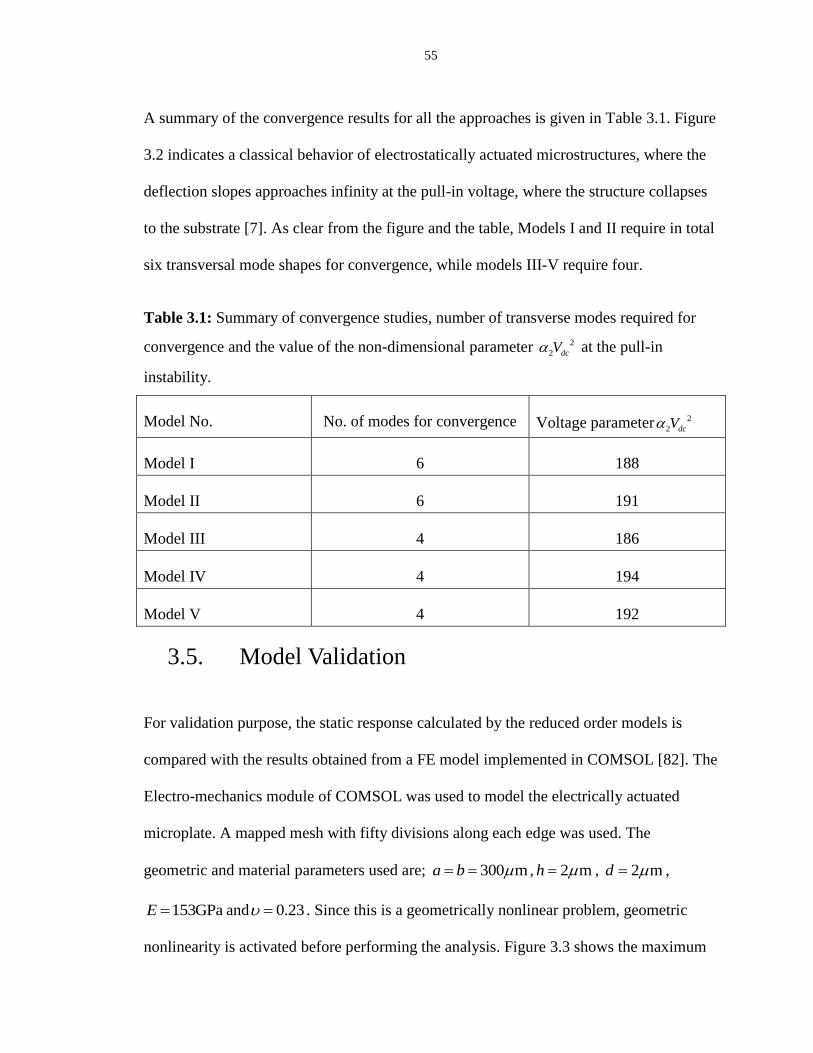
55
A summary of the convergence results for all the approaches is given in Table 3.1. Figure
3.2 indicates a classical behavior of electrostatically actuated microstructures, where the
deflection slopes approaches infinity at the pull-in voltage, where the structure collapses
to the substrate [7]. As clear from the figure and the table, Models I and II require in total
six transversal mode shapes for convergence, while models III-V require four.
Table 3.1: Summary of convergence studies, number of transverse modes required for
convergence and the value of the non-dimensional parameter 2
2 dcV at the pull-in
instability.
Model No. No. of modes for convergence Voltage parameter 2
2 dcV
Model I 6 188
Model II 6 191
Model III 4 186
Model IV 4 194
Model V 4 192
3.5. Model Validation
For validation purpose, the static response calculated by the reduced order models is
compared with the results obtained from a FE model implemented in COMSOL [82]. The
Electro-mechanics module of COMSOL was used to model the electrically actuated
microplate. A mapped mesh with fifty divisions along each edge was used. The
geometric and material parameters used are; 300 ma b , 2 mh , 2 md ,
153GPaE and 0.23 . Since this is a geometrically nonlinear problem, geometric
nonlinearity is activated before performing the analysis. Figure 3.3 shows the maximum

56
deflectionmaxW at the center of the microplate against
dcV up to the pull-in instability. The
figure shows excellent agreement between the results calculated by the ROMs and the FE
model except for model III. Model III predicts the pull-in of the microplate at a lower
voltage. This means that it does not account for the cubic nonlinearity accurately and
only captures the effect of midplane stretching partially. In other words, we can remark
that the shape functions used to represent the in-plane displacements are not accurate
enough to capture the full effect of midplane stretching. All the other models accurately
predict the static response of the microplate.
Although accurate, models I and II require more computational effort as compared with
models IV and V. Nevertheless they use easy-to-handle analytical functions as basis
function in the discretization procedure. Model V calculates exact solution for the in-
plane displacement u and v , hence requires more computational effort to integrate over
the plate domain as compared with model IV, which approximates the solution through
equations (3.32) and (3.33).
Reduced order models are known to be computationally efficient as compared with the
full order finite element models. To highlight the advantage of using reduced order
models over finite element model, we compare the time taken to solve the system when a
DC voltage, 60VdcV was applied. Results for this comparison are given in Table 3.2.
One can note that the time taken by full order FE model is much higher than the reduced
order model because it solves thousands of equations one for each degree of freedom
[43].

57
0 50 100 150 200
0.0
0.1
0.2
0.3
0.4
0.5 1-Mode
3-Mode
5-Mode
6-Mode
7-Mode
V
dc
2
Wm
ax
(a)
0 50 100 150 200 250
0.0
0.1
0.2
0.3
0.4
0.5
0.6
1-Mode
3-Mode
5-Mode
6-Mode
7-Mode
V
dc
2
Wm
ax
0 50 100 150 200 250
0.0
0.1
0.2
0.3
0.4
0.5
0.6
1-Mode
2-Mode
3-Mode
4-Mode
5-Mode
V
dc
2
Wm
ax
(b) (c)
0 50 100 150 200 250
0.0
0.1
0.2
0.3
0.4
0.5
0.6 1-Mode
2-Mode
3-Mode
4-Mode
5-Mode
V
dc
2
Wm
ax
0 50 100 150 200
0.0
0.1
0.2
0.3
0.4
0.5
0.6
1-Mode
2-Mode
3-Mode
4-Mode
5-Mode
V
dc
2
Wm
ax
(d) (e)
Figure 3.2: Convergence of the static results with the number of transversal mode shapes
retained in the reduced order models. Variation of the maximum non-dimensional
deflection maxW at the center of the microplate with the electrostatic voltage parameter
2
2 dcV when 1 , and 1 1 : (a) model I, (b) model II, (c ) model III, (d) model IV, (e)
model V.

58
0 10 20 30 40 50 60 70
0.0
0.2
0.4
0.6
0.8
1.0
Wm
ax(
m)
Vdc
(V)
FE model
Model I
(a)
0 10 20 30 40 50 60 70 80
0.0
0.2
0.4
0.6
0.8
1.0
1.2 FE model
Model II
Vdc
(V)
Wm
ax(
m)
0 10 20 30 40 50 60 70
0.0
0.2
0.4
0.6
0.8
1.0
Wm
ax(
m)
Vdc
(V)
FE model
Model III
(b) (c)
0 10 20 30 40 50 60 70
0.0
0.2
0.4
0.6
0.8
1.0
1.2
Wm
ax(
m)
Vdc
(V)
FE model
Model IV
0 10 20 30 40 50 60 70
0.0
0.2
0.4
0.6
0.8
1.0
1.2
Wm
ax(
m)
Vdc
(V)
FM model
Model V
(d) (e)
Figure 3.3: A comparison of the maximum deflection maxW at the center of the plate,
calculated by the reduced order models with the results obtained from FE model
implemented in COMSOL for various values of dcV , until the pull-in instability: (a) model
I, (b) model II, (c ) model III, (d) model IV, (e) model V.

59
Table 3.2: A comparison of the time taken by the FE model implemented in COMSOL
and the reduced order models to solve the system under an electrostatic DC voltage.
Model Time taken (Seconds)
FE model 125
Model II 0.140
Model III 0.046
Model IV 0.046
Model V 0.031
3.6. Dynamic Analysis
First we present the Eigen frequency analysis of the microplate when deflected under the
DC voltage dcV . The approaches presented in models II-V are used in conjunction with
equations (3.25)-(3.27) to calculate the linear natural frequency of the microplate at
different levels of initial deflection sw under the electrostatic voltage dcV , until the pull-in
instability. The results are compared in Figure 3.4 with the natural frequencies calculated
by the FE model implemented in COMSOL. Model I is not included in the analysis due
to its iterative nature. Results calculated by the ROMs show good agreement with the
ones calculated by FEM model except for model III, which shows significant deviation.
This result agrees with the static results and confirms the remark that model III does not
account accurately for the cubic nonlinearity due to midplane stretching and that the
shape functions used to represent the in-plane displacements are not accurate enough to
capture the full effect of midplane stretching.

60
-10 0 10 20 30 40 50 60 705
10
15
20
25
30
35
40
Vdc
(V)
FE model
Model II
-10 0 10 20 30 40 50 60 705
10
15
20
25
30
35
40
Vdc
(V)
FE model
Model III
(a) (b)
-10 0 10 20 30 40 50 60 705
10
15
20
25
30
35
40
Vdc
(V)
FE model
Model IV
-10 0 10 20 30 40 50 60 705
10
15
20
25
30
35
40
Vdc
(V)
FE model
Model V
(c) (d)
Figure 3.4: The non-dimensional fundamental natural frequency ( 2aD
) of a
square microplate for different levels of dcV until pull-in (stars). Comparison with the
results computed by the FE model implemented in COMSOL (diamonds): (a) model II,
(b) model III, (c ) model IV, (d) model V.
Models II, IV and V accurately predict the non-dimensional natural frequencies of the
microplate. Although accurate, model II entails more computational effort as compared
with models IV and V, since it requires more modes for convergence. However it
employs easy-to-use analytical functions as basis functions in the Galerkin discretization
procedure. Model IV approximates the solution for the in-plane displacements u and v

61
through equations (3.32) and (3.33) while model V calculates exact solution, hence
requires more computational effort to integrate over the plate domain. Nonetheless model
V is easily adaptable to the microplates with other boundary conditions e.g. clamped-
free-clamped-free (CFCF). Moreover one can note that the natural frequency decreases
with the increase of the applied DC voltage and drops rapidly near the pull-in instability,
finally falling to zero at the pull-in instability. This is due to the softening nature of the
electrostatic force, here by softening we mean that the natural frequency decreases with
increase of the electrostatic load. The decrease in the natural frequency of the plate with
the increase in the DC load means that its elastic restoring force is weakening, and hence
reaches eventually to zero when the natural frequency vanishes.
Next we present the dynamic response of the microplate calculated by models II-V, when
actuated with small and large electrostatic forces. Frequency response curves are
generated by actuating the microplate by a harmonic load of amplitude acV superimposed
to dcV load, i.e., (t) ( t)dc acV V V Sin . The Runge Kutta method is used to perform long
time numerical integration to solve the system of governing equations to obtain a stable
steady solution. A stable steady solution is captured such that the transient response is not
contributing to the solution. We fix the non-dimensional parameters as 1 , 1 1 , and
2 1 , and assume that the in-plane external forces are zero i.e. 0xx xy yyN N N . To
get a linear response, we actuate the microplate at a small load of 1VdcV and a harmonic
load of 0.01VacV . For the large vibration response we use 1VacV while dcV is kept the
same. Figure 3.5 shows a comparison of the dynamic responses calculated by models II-

62
V using frequency response curves for the small and large amplitude vibrations of the
microplate.
35.0 35.5 36.0 36.5 37.0
0.000
0.005
0.010
0.015
0.020
0.025
0.030
Model II
Model III
Model IV
Model V
Wm
ax
(a)
34 35 36 37 38 39
0.0
0.1
0.2
0.3
0.4
0.5 Model II
Model III
Model IV
Model V
Wm
ax
(b)
Figure 3.5: Frequency response curves near the non-dimensional fundamental natural
frequency, maximum non-dimensional deflection max ,2 2
a bW of the microplate against
actuating frequency . Response is captured at 1VdcV and (a) 0.01VacV , (b) 1VacV ,
when 1 , 1 1 , 2 1 and a quality factor 1000Q .

63
All the models show good agreement when actuated at small electrostatic loads (Figure
3.5A). All the models show the linear response very close to each other, model II shows a
slight difference of less than 1% from other models. This small difference from other
models appears due to the different kind of shape functions used in this model, which
seems not of good accuracy.
Model III shows a significant deviation from the other models (Figure 3.5B), which show
excellent agreement when actuated at large electrostatic loads. This agrees with the static
and natural frequency results and ratifies the remark that model III does not account
accurately for the cubic nonlinearity. For small actuating forces (Figure 3.5a), all the
models show a resonance near the fundamental natural frequency of the plate. The
geometric nonlinearity is not activated, and in this regime, the linear plate theory can be
used. When large electrostatic loads are used to actuate the large amplitude vibrations of
the plate (Figure 3.5b), the geometric nonlinearity due to midplane stretching is activated.
The plate shows strong hardening behavior due to the geometric nonlinearity, where the
nonlinear resonances appear at higher frequencies. All the models capture the nonlinear
hardening responses of the plate accurately except model III, which fails to capture the
nonlinearity accurately. In this regime, the linear plate theory fails and only a model that
accounts for the geometric nonlinearity can capture the plate response accurately.
Although it sounds appropriate to use any of the models II, IV and V for the investigation
of large amplitude vibrations of microplates, we believe that model V is the most
accurate one since it calculates the exact solution for midplane stretching while for all the
other models we approximate the in-plane displacements using some kind of shape

64
functions. Moreover it can be used with confidence for microplates with other boundary
conditions for example a clamped-free-clamped-free (CFCF) microplate. For such a case
the other models may not be used with the same shape functions. So model V is more
rigorous and versatile and can be used for a microplate with any kind of boundary
conditions.

65
Chapter 4
An Investigation of the Static and Dynamic
Behavior of Electrically Actuated Rectangular
Microplates
In this chapter, we present an investigation of the static and dynamic behavior of the
nonlinear von-Karman plates when actuated by the nonlinear electrostatic forces. The
investigation is based on a reduced order model developed using the Galerkin method,
which rely on mode shapes and in-plane shape functions extracted using a finite element
method. In this study, a fully clamped microplate is considered. We investigate the static
behavior and the effect of different non-dimensional design parameters. The static results
are validated by comparison with the results calculated by a finite element model. The
forced-vibration response of the plate is then investigated when the plate is excited by a
harmonic AC load superimposed to a DC load. The dynamic behavior is examined near
the primary and secondary (superharmonic and subharmonic) resonances. The microplate
shows a strong hardening behavior due to the cubic nonlinearity of midplane stretching.
However, the behavior switches to softening as the DC load is increased. Finally, near-
square plates are studied to understand the effect of geometric imperfections of
microplates.

66
4.1. Introduction
In Chapter 3 we have investigated various approaches to develop reduced order model. In
this chapter we study the static and dynamic behavior of fully clamped rectangular plates
under electrostatic actuation. We use the reduced order model IV presented in Chapter 3
for this investigation. The reduced order model is based on the von-Karman equations of
the plate, in which all three equations of the plate motion are discretized using the
Galerkin method. For validation purpose, we compare the static results computed by the
reduced order model with the results calculated using the FEM software COMSOL [82].
Further the reduced order model is employed to investigate the nonlinear, large amplitude
vibration behavior of the plates. Understanding the nonlinear behavior of microplates
when actuated by large electrostatic loading or when undergoing large motion is
fundamental to the development of the next generation microplates-based MEMS
devices.
We use the problem formulation and reduced order model IV presented in Chapter 3. The
reduced order model is based on the dynamic analogue of nonlinear von-Karman
equations of thin plate.
The reduced order model, which consist of DAEs is solved for the unknown time
dependent coefficients ( )iq t , ( )uq t and ( )vq t . Toward this, we solve equations (3.10) and
(3.11) for ( )uq t and ( )vq t in terms of ( )iq t and then substitute the results into equation
(3.12). This equation is then integrated in time using Runge Kutta. These coefficients are
substituted back into equations (3.31)-(3.33) to get the displacements w , u and v .

67
4.2. Static Analysis
Convergence study of the static results with the number of transverse modes, ( , )i x y
retained in the reduced order model was performed in Chapter 3 and it was found that
four transverse modes are sufficient to get reasonably accurate result. Moreover the
model was also validated by comparing results with the results obtained by FE model.
Figure 4.1: Variation of the maximum non-dimensional deflectionmaxW at the center of
the microplate with the electrostatic voltage parameter 2
2 dcV until pull-in for various
values of aspect ratio when 1 1 .
Here we investigate the effect of different non-dimensional parameters on the static
response of the plate. Figure 4.1 shows the maximum non-dimensional
deflection maxW against 2
2 dcV for various values of the aspect ratio with fixed value
of 1 1 . By increasing , the maximum deflection almost remains constant, but the
voltage instability threshold (pull-in) decreases and saturates near 2
2 75dcV as the aspect
ratio approaches . Figure 4.2 shows the variation of maxW with 2
2 dcV until pull-in

68
occurs for various values of 1 while 1 (square plate). We notice that the maximum
non-dimensional deflection maxW as well as the voltage parameter 2
2 dcV are reduced
for 1 1 , while for 1 1 both quantities increase and maxW seems to stabilize near 0.7
at 1 3 .
Figure 4.2: Variation of the non-dimensional deflectionmaxW at the center of the
microplate with the electrostatic voltage parameter 2
2 dcV until pull-in for various values
of 1 when 1 .
4.3. Dynamic Analysis
In this section we investigate the dynamic response of the square microplate at primary,
super-harmonic of order three, and sub-harmonic of order two resonances of the
fundamental mode. We analyze the dynamics of the microplate by generating frequency
response curves. The Runge Kutta method is used to perform long time numerical
integration to solve the system of DAEs. The stable steady-state solution is captured after

69
making sure that the transient response is no longer contributing to the response. Figure
4.3 shows the time history of the dynamic response of the microplate when actuated at a
DC voltage 3VdcV and an AC voltage 0.1VacV and 35.1 . Figure 4.3a depicts the
diminishing transient response, while Figure 4.3b shows the stable steady-state response.
We use steady-state responses similar to Figure 4.3b to construct the frequency response
curves.
0 10 20 30 40 50
0.02
0.01
0.00
0.01
0.02
0.03
0.04
0.05
Time
Am
plit
ud
e
498.0 498.5 499.0 499.5 500.0
0.00
0.01
0.02
0.03
Time
Am
plit
ud
e
(a) (b)
Figure 4.3: Time history response of the microplate. (a) Transient response. (b) Steady
state response.
4.3.1. Primary Resonance
To investigate the dynamic response at primary resonance, we fix 1 , 1 1 , 2 1 and
assume that the in-plane external forces are zero i.e. 1 12 2ˆ ˆ ˆ 0N N N . With the above
parameters the static pull-in voltage for the microplate is near 14 Volts. We investigate
the nonlinear dynamic behavior of the microplate near primary resonance at a small
harmonic AC voltage, acV superimposed to a DC voltage, dcV , i.e., (t) ( t)dc acV V V Sin .
Figure 4.4 shows the nonlinear response of the microplate when actuated at 3VdcV for

70
various values of acV near primary resonance, which for the linear plate is near 36. The
quality factor is fixed at 250Q , which is related to the damping coefficient by 1cQ
[84]. Our choice of a constant value of Q means that we assumed negligible effect of
squeeze-film damping, which is reasonable assumption assuming that the microplate is
placed inside a vacuum chamber and is operated at reduced pressure. Otherwise,
squeeze-film damping can have strong effect on the dynamics of microplates and needs
to be modeled using Reynolds equation and a structural-fluidic model [7, 48].
Figure 4.4 shows the maximum non-dimensional deflection maxW at the center of the
microplate against the non-dimensional frequency.
Figure 4.4: Maximum non-dimensional deflection maxW at the center of the microplate
against the actuating frequency when actuated at 3VdcV and various values of acV
while quality factor 250Q ; ( F ) forward frequency sweep, ( B ) backward frequency
sweep.

71
The microplate exhibits strong hardening effect due to the cubic nonlinearity, which
comes into play due to midplane stretching. The hysteresis in the curves is captured by
performing forward and backward frequency sweeps. Nonlinear resonance peaks occur
near 36.15 for 0.1VacV while it is at 36.6 for 0.3VacV and 36.9 for 0.5VacV .
Further we notice that there exist multiple stable solutions over some range of frequency
and amplitude jumps from higher to lower or lower to higher values depending on the
type of frequency sweep.
Figure 4.5 shows the frequency response curves of the microplate when actuated at
7VdcV for various values of acV with a quality factor 250Q . An overlap of stable
solutions exists when actuated at 0.2VacV contrary to the responses at 0.4VacV and
0.6VacV , respectively.
Figure 4.5: Maximum non-dimensional deflection maxW at the center of the microplate
against the actuating frequency when actuated at 7VdcV and various values of acV
while quality factor 250Q .

72
A gap between the two stable solutions starts to emerge in the case of 0.4VacV by the
forward and backward frequency sweeps. This gap might indicate that the microplate
becomes unstable at that actuating voltage and pulls on the stationary electrode. This kind
of instability is called dynamic pull-in instability, which usually occurs at a lower DC
load superimposed to a small harmonic load [7, 24, 84, 85]. Another possibility exists,
especially in the case of 0.4VacV , that this gap is created due to the numerical
divergence of the time integration scheme, due to its inability to find suitable initial
conditions that lead to a stable periodic orbit. In other words, this might indicate highly
fractal behavior, which usually gets stronger as the system approaches the dynamic pull-
in regime [85] .To confirm if this divergence is due to fractal behavior or due to pull-in
exactly, one should resort to other numerical techniques to find periodic motions, such as
shooting and finite difference methods as well as basin of attraction analysis [7, 84]. The
response on the other hand for the case of 0.6VacV is most likely an indication of a
pull-in band, since as reported in [84], further increase in acV widens the pull-in band gap
between the stable solutions and makes the upper stable branches terminated at lower
values [84].
4.3.2. Secondary Resonances
Due to the cubic nonlinearity from midplane stretching and quadratic nonlinearity of the
electrostatic force, the plate is expected to exhibit several secondary resonances [7, 86].
These include super harmonic resonances near one-third and one-half the fundamental
natural frequency as well as subharmonic resonances near twice and three times the
fundamental natural frequency. As case studies, in this paper, we investigate the dynamic

73
response of the microplate near the super-harmonic resonance of order three and then
near the subharmonic resonance of order half. We use the non-dimensional parameters of
Section 4.4.1.
A. Super-harmonic Resonance at 1
3
The generated frequency response curves reveal some interesting phenomena in this case.
First, Figure 4.6 shows the response at 9VdcV for various values of acV .
Figure 4.6: Frequency response curves near super-harmonic resonance, 1
3
of the
fundamental natural frequency. Maximum non-dimensional deflection maxW at the center
of the microplate against the actuating frequency when actuated at 9VdcV and various
values of acV while quality factor 250Q .

74
The response at 2.1VacV shows a clear hardening behavior. Now increasing the AC
voltage to 2.3VacV and 2.4VacV , the microplate becomes unstable and jumps to another
stable state with higher amplitude of vibration near max 0.77W .
This behavior is contrary to the one near primary resonance where the microplate jumps
onto the stationary electrode as dynamic pull-in. This can be due to the fact that the
response is in the verge of shifting from hardening to softening effect. This is clarified in
Figure 4.7, which shows the frequency responses at 10VdcV for various acV . Figure 4.6
and Figure 4.7 depict the transition from hardening to softening behavior.
Figure 4.7: Frequency response curves near super-harmonic resonance, 1
3
of the
fundamental natural frequency. Maximum non-dimensional deflection maxW at the center
of the microplate against the actuating frequency when actuated at 10VdcV and various
values of acV while quality factor 250Q .

75
This is expected with the increase of the DC voltage, which tends to change the effective
nonlinearity of the system. Essentially, the effective nonlinearity is dominated by the
midplane stretching (positive cubic in nature) for low value of DC voltage, and thus the
plate exhibits hardening behavior. On the other hand, the electrostatic nonlinearities
(quadratic in nature) dominate the overall nonlinearities leading to softening behavior at
higher values of DC voltage [7, 87]. This observed behavior is expected also for the
primary resonance case. Next, we investigate the amplitude jumps in Figure 4.6 by
plotting phase portraits of the response near terminal points of the lower and upper stable
branches. Figure 4.8 and 4.9 show the periodic orbits of the stable branches
at 2.3VacV and 2.4VacV , respectively.
a
0.1 0.0 0.1 0.2 0.3 0.4
5
0
5
Deflection
Ve
locity
b
0.2 0.0 0.2 0.4 0.6
10
5
0
5
10
Deflection
Ve
locity
c
0.4 0.2 0.0 0.2 0.4 0.6 0.8
20
10
0
10
20
Deflection
Ve
locity
d
0.00 0.05 0.10 0.15 0.20 0.25
4
2
0
2
4
Deflection
Ve
locity
Figure 4.8: Phase portraits for the lower and upper stable branches of the Figure 4.6
for 2.3VacV ; (a) 11.12 , (b) 11.176 , (c) 11.178 , (d) 11.194 .

76
Figure 4.8 shows that the orbit size increases as the actuation frequency increases until
the maximum value of deflection amplitude max 0.6W is reached near the terminal point
of the lower stable branch at 11.176 . Beyond this point, we note that the plate jumps
to a higher amplitude of vibration, max 0.8W at 11.178 . The plate jumps back to a
lower amplitude of vibration, max 0.27W at 11.194 . A similar response is depicted in
Figure 4.9 for a higher AC load.
a
0.2 0.1 0.0 0.1 0.2 0.3 0.4 0.510
5
0
5
Deflection
Ve
locity
b
0.2 0.0 0.2 0.4 0.6
10
5
0
5
10
Deflection
Ve
locity
c
0.4 0.2 0.0 0.2 0.4 0.6 0.8
20
10
0
10
20
Deflection
Ve
locity
d
0.00 0.05 0.10 0.15 0.20 0.25
4
2
0
2
4
Deflection
Ve
locity
Figure 4.9: Phase portraits for the lower and upper stable branches of the Figure 4.6
for 2.4VacV ; (a) 11.12 , (b) 11.138 , (c) 11.14 , (d) 11.204 .
A. Sub-harmonic Resonance at 12
In this section we investigate the dynamic response of the plate near sub-harmonic
resonance of order one half. Figure 4.10a shows, as expected, a hardening response. This
77
hardening behavior shifts to softening behavior by further increasing the DC voltage.
During this transition, Figure 4.10b, an upper discrete dynamical solution is created of
relatively large amplitude (near maxW =0.8), similar to the observed behavior in Figure 4.6.
Figure 4.10c shows softening behavior at a higher value of DC voltage. The upper stable
branch in the case of softening behavior stays high with significantly large amplitude as
compared with lower branches for a considerably large band of actuation frequency.
4.3.3. Dynamic Behavior of Imperfect Square Plates
Next, we investigate the dynamic behavior of imperfect square plates near the second
symmetric-symmetric mode, which corresponds to symmetric-symmetric degenerate
modes of square plates [88-91]. By imperfect square microplate we mean that is close
to 1. Such an imperfection comes practically when fabricating a square plate, which then
due to unavoidable fabrication imperfections, will come as a near square plate. We
actuate the microplate at small DC and AC voltages. Non-dimensional parameters remain
the same as in Section 4.3.1 except , which we change slightly to introduce the
imperfection. A square microplate exhibits degenerate mode due to the symmetrical
geometry. Figure 4.11a shows the response of a perfect square plate, i.e., 1 while
Figures 4.11b-d show the responses when is slightly varied ( 0.999 , 0.995 ,
and 0.99 ).
It is shown that slightly varying the value of breaks the geometrical symmetry and
hence the degenerate modes become distinct modes of vibration at distinct frequencies.
As a consequence two corresponding resonances appear very close to each other.

78
(a) 9VdcV and 0.5VacV .
(b) 10VdcV and 0.5VacV . (c) 11VdcV and 0.5VacV .
Figure 4.10: Frequency response curves near sub-harmonic resonance near 12 .
Maximum non-dimensional deflection maxW at the center of the microplate against the
actuating frequency for a quality factor 250Q .
These neighboring resonances are of interest, for instance, for mass sensing MEMS
applications. It is noticed that for very small imperfections the amplitude of the new
resonance is very small. By further increasing the imperfection, the amplitudes of both
resonances become the same but are smaller than the one with the ideal square plate. This
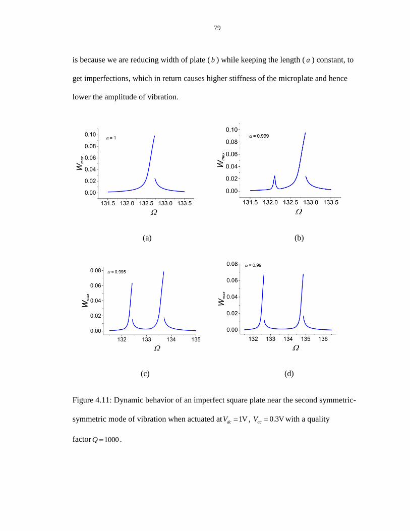
79
is because we are reducing width of plate ( b ) while keeping the length ( a ) constant, to
get imperfections, which in return causes higher stiffness of the microplate and hence
lower the amplitude of vibration.
(a) (b)
(c) (d)
Figure 4.11: Dynamic behavior of an imperfect square plate near the second symmetric-
symmetric mode of vibration when actuated at 1VdcV , 0.3VacV with a quality
factor 1000Q .

80
Chapter 5
Initially Curved Micro-plates under Electrostatic
Actuation
In this chapter, we investigate the mechanical behavior of initially curved microplates
under electrostatic actuation. It is common for microplates to undergo an initial curvature
imperfection, due to the micro fabrication process, which affects significantly their
mechanical behavior. Here, we develop a reduced order model based on the Galerkin
procedure to simulate the static and dynamic behavior of the microplate. We investigate
the convergence of static results with the number of modes retained in the reduced order
model. We validate the reduced order model by comparing the calculated static behavior
and the fundamental natural frequency with those computed by a finite element model.
The static behaviour of the microplate is investigated when applying a DC voltage. Then,
the dynamic behaviour of the microplate is examined under the application of a harmonic
AC voltage superimposed to a DC voltage. As case studies, we consider two different
profiles of the initial curvature imperfection and study their effects on both the static and
dynamic responses of the microplates.

81
5.1. Introduction
MEMS devices are commonly made up of microbeams and microplates [8, 12-24]. These
are used in various applications, such as micropumps in micro fluidics, biomedical and
cooling applications [15-17, 25-27] , microphones [19-21], mass sensors [22, 23] and
resonators [24, 30] to realize sensors and microswitches [31, 32]. These underlying
structures undergo imperfections during the micro fabrication process due to residual
stresses. To model such structures, accurate models are needed, which properly account
for this initial imperfection.
We investigate next the effect of initial curvature profile on the static and dynamic
behavior of the plate. Towards this, we consider two commonly encountered profiles of
initial curvature and compare their effects on static behavior, eigen frequencies and
dynamic behavior. Also we compare the results obtained from reduced order model with
the results from a FE model for some cases to validate the model.
5.2. Problem Formulation
In this chapter, we consider a clamped-free-clamped-free (CFCF) rectangular microplate
having an initial curvature imperfection0 ( , )w x y and in the domain 0 x a and
0 y b , as shown in Figure 2.2. The problem was formulated in Chapter 2, where the
governing equations (2.49)-(2.51) were derived using the modified von-Karman strains.
The associated boundary conditions are given in equations (2.52)-(2.59).
For convenience, we introduce the non-dimensional variables (denoted by hats)

82
ˆx
xa
, ˆy
yb
, ˆw
wd
, 00
ˆw
wd
, 2
ˆau
ud
, 2
ˆav
vd
, ˆt
tT
(5.1)
Substituting equation (5.1) into equations (2.49)-(2.51) and dropping the hats, for
convenience, we get the following equations:
22 2 2 2 2
0 0
2 2 2 2 2 2
2 22 2 2 2
0 0 0 0
2 2 2 2 2
1 1
2 2
1 10
2 2
w wu v u w w w w
x x y y x x x x x x
w w w ww w w w w w w w
y x y y x y y x y x y x y x y
(5.2)
2 22 2 2 2 2
0 0
2 2 2 2 2
2 22 2 2 2
0 0 0 0
2 2 2
1 1 1
2 2
1 10
2 2
w wv u v w w w w
y x y x y y y y y y
w w w ww w w w w w w w
x x y x x y x x y y x y x y x
(5.3)
24 4 4 2 2 22
2 0 1 12 224 2 2 2 4 4 2 2 2 2
2 2 2 2 22
1 2 2 2 2 2 2
2 1 2 1 ˆ ˆ ˆˆ 3 1
1 1 1 112 1
i i iV tw w w w w w w w
c N N Nx x y y t t x x y yw
u w w v w w u v w
x x y y x y y x x
2 2 2 2 2
0
2 2 2 2
2 2 2 2 22 01 2 2 2 2 2 2 2 2
2
0
2
1
2
1 1 1 112
2 2
1
y
ww w w w w w
x x y x x x y
ww w w w w w
y x y y y x y
ww w w w
x y x y x y
2 2
0
2 2 2 2 22 0 0 0 0 01 2 2 2 2 2 2
2 2 2
0 0
2 2
2
1
1 1 1 112 1
1
2
12
ww w w
x y x y x y
w w w w wu v u v
x x y y x y y x x y
w ww
x x y
2 2
0 0 0
2 2
2 2 2 2 2
0 0 0 0 0
2 2 2 2 2 2 2 2
2 2 2
0 0 0 0 0
2
1 1 1 1
2 2
1
w w ww
x x x y
w w w w ww w
y x y y y x y
w w w w ww w w w
x y x y x y x y x y x y
(5.4)
The associated boundary conditions for the non-dimensional equations are

83
Clamped edges at x=0 and x=1
0u (5.5)
0v (5.6)
0w (5.7)
0w
x
(5.8)
Free edges at y=0 and y=1
2 21 1
02
v u w w
y x y x
(5.9)
0u v w w
y x x y
(5.10)
2 22
2 20
w w
y x
(5.11)
3 3
2
3 22 0
w w
y y x
(5.12)
The parameters appearing in equations (5.2)-(5.12) are
b
a ,
0
a
h ,
1
d
h ,
2
4
2 3 3
6 1
a
E h d
,
4
ˆ
cac
TD and
21ˆ i i
j jN NEh
. (5.13)

84
5.3. Reduced Order Model
This approach follows the method outlined in [11, 43, 83] . In this approach, the out-of-
plane deflection w is expressed as
1
( ) ( , )m
i
i
iw q t x y
(5.14)
where ( , )i x y are the out-of-plane mode shapes of the plate and ( )iq t are the
corresponding unknown time dependent coefficients. Substituting equation (5.14) into
equations (5.2) and (5.3), we obtain the following equations:
2 2 22 2 2
2 2 2 2 2 2 2,
2 2 2
0 0 0
2 2 2 2
1 1 1 1
2 2 2 2
1 1
2 2
k l k l k lk l
l
k k
k
k
k
k
u v u
x x y y x x y x y x y
w w w
x x y
q q
x y x yq
2 2 2
0 0 0
2 2 2 2
01 1
2 2
k k kw w w
x x y x y x y
(5.15)
2 2 2 22 2 2
2 2 2 2,
2 2 2
0 0 0
2 2
1 1 1 11
2 2 2 2
1 11
2 2
1
k lk l k l k l
k l
k k k
kk
k
v u v
y x y x y y x x y y x
w w w
y y x x y y x
y
q q
q
2 2 2
0 0 0
2 2
01 1
2 2
k kw w w
y x x y y x
(5.16)
Equations (5.15) and (5.16) are nonhomogeneous coupled linear PDEs in u and v . Since
these equations are linear, the principle of superposition can be used to determine the
solution foru and v in the form [83]

85
,k
kl k
k l k
l k
u q q u q u (5.17)
,k
kl k
k l k
l k
v q q v q v (5.18)
where the superscript kl denotes the in-plane displacements klu and klv caused by the
loadskl
xf andkl
yf defined as
2 2 2
2 2 2 2
1 1
2 2
k l k l kk
xll
x x yf
x y x y
(5.19)
2 2 2
2 2
1 11
2 2
k l k lkl k ly
y y x x y y xf
(5.20)
and similarly superscript k denotes the in-plane displacements ku and kv caused by the
loadsk
xf andk
yf defined as
2 2 2
0 0 0
2 2 2 2
2 2 2
0 0 0
2 2 2 2
1 1
2 2
1 1
2 2
k k
k
k k
x
k
k
w w w
x x y x y x y
w w w
x x y x y x y
f
(5.21)
2 2 2
0 0 0
2 2
2 2 2
0 0 0
2 2
1 11
2 2
1 11
2 2
k k k
k k k
k
y
w w w
y y x x y y x
w w w
y y x x y y x
f
(5.22)

86
Equation (5.4) is multiplied by 2
1 w to treat the electric force term exactly with no
approximation. Now by substituting equations (5.14), (5.17) and (5.18) into equation
(5.4), multiplying by ( , )i x y and integrating over the plate domain we get the reduced
order model for the governing equations. The reduced order model consists of a system
of nonlinear coupled ODEs in ( )iq t . This system of ODEs is solved for ( )iq t numerically
using the Runge Kutta method and is substituted back into equation (5.14), (5.17), and
(5.18) to obtain ,w u , and v respectively.
5.4. Results
In the following, we study the effect of the initial curvature on the static and dynamic
behavior. The effect of initial curvature on fundamental natural frequency is also
investigated. Toward this, we consider two profiles of initial curvature commonly
encountered in micro fabricated structures:
2
01 0max 1 ( )w w Cos x (5.23)
2
02 0max 1 ( ) ( y)w w Cos x Sin
(5.24)
where 0maxw is the maximum curvature at the center of the microplate. Profile 01w
assumes variation in shape along the x axis only (cylindrical bending shape) while profile
02w assumes variation in shape along both x and y axis.

87
5.4.1. Static Results
First, we investigate the convergence of the static solution with the number of transversal
modes of vibration retained in the reduced order model. We assume that no in-plane
external forces are applied to the microplate, i.e., 1 12 2ˆ ˆ ˆ 0i i iN N N . To calculate the
static deflection of the microplate under a DC load, the time derivatives are dropped in
the reduced order model, (t)V is replaced withdcV , and the time dependent unknown
coefficients ( )iq t are replaced with constant coefficientsiq . This results in a system of
nonlinear algebraic equations, which is numerically solved foriq . Then equation (5.14) is
used to find the non-dimensional transversal deflection. The static response is calculated
using various values of voltage parameter 2
2 dcV until the pull-in instability (which occurs
when the electrostatic force overcomes the mechanical force from the structure [7] ).
Figure 5.1 shows the stable branch of the static response at the centre of the microplate
against voltage until pull-in.
One can note that the deflection curve is limited by the pull-in instability, where the slope
of the curve approaches infinity. As noted, three modes are sufficient to get a reasonably
accurate solution. The convergence study is based on non-dimensional parameters, and
hence is not specific to any plate of a particular geometry or material.
Next, we investigate the effect of the initial curvature profiles on the static response of
the microplate. The length and width of the microplate are 250a m and 125b m ,
respectively. The thickness of the microplate is 1.75h m and the capacitor gap is
2.5d m . The material parameters used in this investigation are 160GPaE , 0.25

88
and 32500Kg/m . The static response is calculated using various values of DC voltage
dcV until the pull-in for various values of initial curvature imperfections. Figure 5.2
shows the variation of pull-in voltage threshold dc pullV with the initial imperfection 0maxw
for the considered profiles 01w and
02w .
0 20 40 60 80
0.0
0.1
0.2
0.3
0.4
0.5
1-Mode
2-Mode
3-Mode
4-Mode
V
dc
2
Wm
ax(a
/2,b
/2)
Figure 5.1: Convergence of the static response with the number of transverse modes
retained in the reduced order model. Variation of the maximum non-dimensional
deflection maxW at the center of the plate with the electrostatic voltage parameter
2
2 dcV when 1 and 1 1 .
For validation purpose, similar results calculated by a finite element (FE) model
implemented in COMSOL Multiphysics [82] are also shown for profile01w .The
Electromechanics module of COMSOL was used to model the electrically actuated
microplate. A mapped mesh with 50 elements along the length and 25 along the width of
the microplate was used. The geometric and material parameters used for the FE model

89
are the same as mentioned in this section. Since this is a geometrically nonlinear problem,
the geometric nonlinearity is activated before performing the analysis. The results
calculated by the reduced order model show good agreement, particularly for small
values of imperfection. As the initial imperfection increases, the reduced order model
results show deviation from the FE model results. This can be attributed to the use of
mode shapes of a linear flat plate as basis functions in the reduced order model. To
improve the accuracy for large curvatures, one may need to use mode shapes of a
similarly curved plate or some other adequate basis functions.
-0.2 0.0 0.2 0.450
60
70
80
90 P1 (Reduced Order Model)
P1 (Finite Element Model)
P2 (Reduced Order Model)
w0max
Vp
ull (V
)
Figure 5.2: Variation of the DC voltage pullV at pull-in with the initial imperfection
calculated by the reduced order model for curvature profiles 01w and 02w . Results
calculated by the FE model are also compared with the results of the reduced order model
for profile 01w .
One can note that although both profiles affect the pull-in voltage, 01w shows a
significantly large influence as compared to the effect of 02w . Moreover for profile
02w ,

90
the pull-in voltage reduces even when it is curved away from the other stationary
electrode while for01w the pull-in voltage varies almost linearly.
5.4.2. Dynamic Results
In this section, first we investigate the effect of the initial curvature profile on the free
vibration of the microplate without application of any electrostatic load. Towards this, we
drop the nonlinear terms in the reduced order model to solve the linear eigenvalue
problem to get the natural frequency. Figure 5.3 shows the variation of non-dimensional
natural frequency against the initial curvature 0maxw . We note that the natural frequency
rises significantly with the increase of initial curvature of profile 01w but for curvature of
profile02w , it only rises slightly and then starts decreasing. It signifies that both profiles
have significantly different effect on the natural frequency of the microplate. Lin and
Chen [68] and Liu and Yeh [70] have remarked that fundamental natural frequencies are
significantly influenced by the initial curvature.
For validation purpose, the natural frequency results calculated by the FE model
implemented in COMSOL Multiphysics [82] are also shown for profile 01w in Figure
5.3a, which show excellent agreement with the results calculated by the reduced order
model, thereby validating the current model.

91
0.0 0.2 0.4 0.6 0.8 1.0 1.220
25
30
35
40
45
ROM
COMSOL
w0max
non
0.0 0.1 0.2 0.3 0.4 0.5
16
18
20
22
24
26
non
w0max
(a) 01w (b) 02w
Figure 5.3: Variation of the non-dimensional fundamental natural frequency
2
non aD
with the initial imperfection 0maxw . Results calculated by the FE model
are also compared with the results of the reduced order model for profile 01w .
Next, we investigate the effect of the initial curvature on the forced dynamic responses of
the microplate. The dynamic behavior of the microplate is examined by generating
frequency response curves in the neighborhood of the primary resonance under the
application of a harmonic AC voltage superimposed to a DC voltage, i.e.,
(t) ( t)dc acV V V Sin . The Runge Kutta method is used to perform long time numerical
integration to solve the system of ODEs. The stable steady-state solution is captured after
making sure that the transient response is no longer contributing to the response.
First, we study the effect of the initial curvature on the linear response of the microplate.
A small AC voltage 1VacV is superimposed to a small DC voltage 1VdcV to capture
the linear response. Figure 5.4 shows the frequency response curves of the microplate

92
with curvature profiles01w and
02w for various values of initial curvature0maxw . One can
note that for the profile01w the resonance frequency increases with increasing the initial
curvature and for0max 0.4w , resonance frequency has increased about 22%. For
02w , the
resonance frequency rises slightly with the initial curvature but then drops below the
resonance of a flat plat.
21 22 23 24 25 26 27 28
0.000
0.002
0.004
0.006
0.008
0.010
0.012
0.014 w
0max= 0
w0max
= 0.2
w0max
= 0.4
Wm
ax
21.0 21.5 22.0 22.5 23.0 23.5
0.000
0.002
0.004
0.006
0.008
0.010
0.012 w0max
=0
w0max
=0.2
w0max
=0.4
Wm
ax
(a) 01w (b) 02w
Figure 5.4: Frequency response curves showing the linear responses of the microplate for
various values of initial curvature imperfection for profile 01w and 02w when the microplate
is actuated by a 1VacV superimposed to a 1VdcV , and a quality factor 1000Q .
Next, we examine the effect of the initial curvature on the nonlinear large amplitude
vibrations of the microplate. To capture the nonlinear large amplitude vibrations, we
apply a harmonic AC voltage 5VacV superimposed to a DC voltage 5VdcV . Figures
5.5 and 5.6 show the frequency response curves for various values of initial curvature
imperfection0maxw for profiles
01w and02w .

93
20 22 24 26 28 30 32
0.0
0.1
0.2
0.3
0.4 w
0max=0
w0max
=0.1
w0max
=0.2
w0max
=0.3
w0max
=0.4
w0max
=0.5
Wm
ax
Figure 5.5: Variation of the maximum non-dimensional deflection maxW at the center of
the plate with the actuation frequency for various values of initial curvature
imperfection for profile 01w when 5VacV , 5VdcV , and quality factor 1000Q .
20 21 22 23 24 25
0.0
0.1
0.2
0.3
0.4 w0max
=0
w0max
=0.1
w0max
=0.2
w0max
=0.3
w0max
=0.4
Wm
ax
Figure 5.6: Variation of the maximum non-dimensional deflection maxW at the center of
the plate with the actuation frequency for various values of initial curvature
imperfection for profile 02w when 5VacV , 5VdcV , and quality factor 1000Q .

94
The dynamic response of the flat microplate is a hardening behavior, which is then
softened with the increase of initial imperfection for both considered profiles that
ultimately converts to softening behavior for certain value of initial imperfection. Similar
softening effect due to the initial curvature for completely free plates was reported by
Alijani and Amabili [71] for large amplitude vibration. Lin and Chen [68] has also
remarked about the conversion of hardening behavior to softening one depending on
initial curvature.
We also investigate the transition of hardening behavior of the microplate to the softening
behavior with the DC voltage load. We apply a small 1VacV superimposed todcV and
capture the frequency response curves for various values of DC voltage. Figure 5.7 shows
that the nonlinear dynamic response of the microplate converts to softening
when 55VdcV is applied for both profiles at0max 0.2w .
19 20 21 22 23 24 25
0.0
0.1
0.2
0.3
0.4
0.5 V
dc= 15
Vdc
= 35
Vdc
= 55
Wm
ax
19 20 21 22 23 24 25 26 27
0.0
0.1
0.2
0.3
0.4
0.5
0.6 V
dc= 15
Vdc
= 35
Vdc
= 55
Wm
ax
(a) 01w , 0max 0.2w (b) 02w ,
0max 0.2w
Figure 5.7: Frequency response curves depicting the transition from hardening to
softening response of the microplate with increasing dcV with 1acV .

95
Chapter 6
Initially Curved Microplates under Electrostatic
Actuation: Experimental Case Study and Model
Validation
We adopt the dynamic analog of the von-Karman governing equations of imperfect plates
to model and simulate the nonlinear mechanical behavior of an initially curved
microplate made of silicon nitride. The static behaviour of the microplate is investigated
when applying a DC voltage, Vdc. Then, the dynamic behaviour of the microplate is
examined under the application of a harmonic AC voltage, Vac, superimposed to Vdc.
Simulation results show good agreement with the experimentally measured responses.
6.1. Introduction
In this chapter we investigate the nonlinear mechanical behavior of an initially deflected
CFCF microplate experimentally. Such microplates are fabricated with the same
procedure as in clamped-clamped microbeams. However, they offer the advantage of
bigger surface area, for instance, which is of an advantage for surface functionalization in
mass sensing applications. Also they offer larger flow rates in micropumping
applications.

96
A silicon nitride microplate is fabricated using the micro-fabrication process detailed in
[92]. The fabrication has been done by Dr. Mohammed L. Bellaredj at the KAUST
Advanced Nano Fabrication (ANIC) laboratory. These microplates have acquired initial
curvature during fabrication process due to residual stresses. These have been tested in
collaboration with Dr. M. L. Bellaredj and Dr. A. Ramini. Both the static and dynamic
analysis are performed and results are compared with the simulation results for the model
validation purpose.
6.2. Experiment
First, we used optical interferometry profiler to characterize the dimensions and geometry
of the microplate without any electrostatic load. We found that the microplate has an
initial deflection due to residual stresses caused by the micro fabrication process (Figure
6.1). The maximum initial deflection 0w at the center of the microplate is recorded to be
0max 0.47w m . The length and width of the microplate are 250a m and 125b m ,
respectively. The thickness of the microplate is 1.75h m and the gap d is found to
be 2.25d m .
Since the silicon nitride (Si3N4) is a dielectric material with a dielectric constant
7rSiNx , a conductive layer of gold is applied on top of the microplate. The equivalent
capacitor gap is thus the air gap plus the contribution from the silicon nitride microplate.
Equivalent capacitor gap eqd for the parallel plate capacitor is calculated by using the
formula SiNxeq
rSiNx
td d
[93] and is found to be 2.464eqd m .

97
(a)
(b)
(c)
Figure 6.1: (a) Optical microscope view of the fabricated microplate, (b) deflection
profile along the length of the microplate, and (c) deflection profile along the width of the
microplate.

98
Figure 6.2 shows the used experimental setup. It consists of a Micro System Analyzer
[94] which is a laser Doppler vibrometer, a vacuum chamber; which houses the
microplate, a vacuum pump to reduce the pressure, and a data acquisition system DAQ.
Figure 6.2: Experimental setup showing the Micro-System Analyzer MSA-500, a vacuum
chamber, a vacuum pump and data acquisition system DAQ.
To measure the static response of the plate under electrostatic loads, we apply a DC
load dcV and capture the deflection at the center of the microplate using also the optical
interferometry profiler. Figure 6.3 shows the maximum deflections maxW measured at the
center of the microplate against dcV until the plate pulls onto the stationary electrode. The
measured pull-in voltage pullV is found near 75V.

99
0 10 20 30 40 50 60 700.0
0.2
0.4
0.6
0.8
1.0
1.2
Vdc V
WM
ax
m
Figure 6.3: The maximum deflection maxW measured at the center of the microplate
against dcV until pull-in, at a 3.3 mTorr chamber pressure.
To investigate the dynamic response, first we actuated the microplate by applying a white
noise signal to identify the linear resonance frequencies. Figure 6.4 shows the velocity
responses of the microplate to a white noise signal. The figure shows a primary resonance
somewhere near 250 kHz along with some higher mode resonances.
Figure 6.4: The velocity response of the microplate to the white noise actuation signal at
Vdc=5V, Vac=10V and 3.3 mTorr chamber pressure.

100
245 246 247 2480.00
0.02
0.04
0.06
0.08
0.10
0.12
0.14
KHz
WM
ax
m
235 240 245 250 255 2600.0
0.2
0.4
0.6
0.8
KHz
WM
ax
m
(a) Vdc=1V, Vac=1V (b) Vdc=5V, Vac=5V
235 240 245 250 255 2600.0
0.2
0.4
0.6
0.8
KHz
WM
ax
m
235 240 245 250 255 2600.0
0.2
0.4
0.6
0.8
KHz
WM
ax
m
(c) Vdc=10V, Vac=5V (d) Vdc=15V, Vac=5V
Figure 6.5: Frequency response plots in the neighborhood of the fundamental natural
frequency of the microplate at various combinations of applied loads at a 3.3 mTorr
chamber pressure.
Next, to find the forced response, a harmonic load of amplitude acV superimposed to dcV
was applied to the microplate, i.e., (t) ( t)dc acV V V Sin . We performed frequency
sweeps in the neighborhood of the fundamental natural frequency at various applied
voltages. First we applied small voltages to capture the linear response. We could capture
a nearly linear response at 1VacV and 1VacV (Figure 6.5a). The fundamental natural
frequency of the microplate f is found to be around 246.3 KHz. Afterwards nonlinear

101
responses at various higher voltages were captured (Figure 6.5b-c). The microplate shows
the nonlinear hardening response due to midplane stretching. Nevertheless the hardening
response has been weakened due to the initial imperfection. This weakening effect will be
further explained in the next section when we compare the theoretical results of a flat
plate with the experimental results of the initially deflected microplate. Figure 6.5d shows
a strange behavior near 250KHz , where the maximum deflection seems to be
reduced slightly. This can be because of the laser beam getting somewhat away from the
center of the microplate and hence recording a lower deflection.
6.3. Theory
In this section we present the theoretical static and dynamic results calculated by reduced
order model of Chapter 5 and compare with the experimentally measured data for model
validation. We use the plate parameters found by experiment along with the material
parameters 160GPaE , 0.25 and 32500Kg/m . The initial imperfection profile
of the microplate is approximated by the function 4
0 1 ( ) ( y)w Cos x Sin
,
where is the parameter that controls the maximum initial deflection at the center of the
microplate. Figure 6.6 shows plots of the assumed profile of initial curvature
imperfection along the length and the width of the plate respectively.
To calculate the static deflection of the microplate under a DC load, we drop the time
derivatives in the reduced order model; and the time dependent unknown coefficients
( )iq t are replaced with constant coefficients iq , and (t)V is replaced with
dcV . This

102
results in a system of nonlinear algebraic equations, which is numerically solved for iq .
Then equation (5.14) is used to find the transversal deflection.
0.0 0.2 0.4 0.6 0.8 1.0
0.4
0.3
0.2
0.1
0.0
Length normalized
Defle
ctio
nm
0.0 0.2 0.4 0.6 0.8 1.0
0.4
0.3
0.2
0.1
0.0
Width normalized
Defle
ctio
nm
(a) (b)
Figure 6.6: Plots of the assumed profile passing through the center of the microplate, (a)
along the length of the microplate, (b) along the width of the microplate.
The static response is calculated using various values of DC voltage dcV until the pull-in.
The results are compared with the static responses measured experimentally in Figure
6.7. The results show excellent agreement with the experimentally measured data thus
validating the reduced order model.
The dynamic response of the microplate is calculated by applying a acV superimposed
to dcV , i.e., (t) ( t)dc acV V V Sin . The quality factor Q is approximated from the
experimental frequency response at 1VacV and 1VdcV (Figure 6.5a) and is found to be
around 785. This value is used in the simulations.

103
Figure 6.7: The maximum deflectionmaxW at the center of the microplate against
dcV until
the pull-in; calculated by the reduced order model accounting for initial curvature and
measured experimentally. Results calculated by reduced order model for the flat plat are
also shown for comparison.
An in-plane tensile force 0.7N/mxxN was applied to match the experimentally
measured fundamental natural frequency. The initial imperfection parameter is set such
that the maximum initial imperfection at the center of the microplate is
0max 0.4718w m . Figure 6.8 shows the comparison of the dynamic responses
calculated by the reduced order model with the experimentally measured results in the
neighborhood of the fundamental natural frequency at various combinations of applied
voltages. We note the results calculated by reduced order model show good agreement
with the experimentally measured response.

104
245 246 247 2480.00
0.05
0.10
0.15
KHz
WM
ax
m
(a) Vdc=1V, Vac=1V
235 240 245 250 255 2600.0
0.2
0.4
0.6
0.8
KHz
WM
ax
m
235 240 245 250 255 2600.0
0.2
0.4
0.6
0.8
KHz
WM
ax
m
(b) Vdc=5V, Vac=5V (c) Vdc=10V, Vac=5V
Figure 6.8: Comparison of the dynamic responses in the neighborhood of the
fundamental natural frequency, calculated by the reduced order model ‘+’ with the
experimentally measured results ‘*’ at various combinations of applied voltages.
Next, we compare the dynamic response of a flat plate with the experimentally measured
response of the initially deflected microplate. Towards this we set the initial
imperfection 0 0w , and capture the frequency response curve near the fundamental
natural frequency. Figure 6.9 shows that the flat plate exhibits stronger hardening
nonlinear response as compared to the experimentally measured response of the

105
fabricated microplate. Figure 6.9 reveals that the reduced order model without taking into
account the effects of initial imperfection produces erroneous results. This is because the
initial imperfection introduces softening effects due to the quadratic nonlinearity, which
weakens the hardening behavior. Similar softening effect due to initial curvature
imperfection was also captured experimentally by Alijani and Amabili [71] for
completely free rectangular plates for large amplitude vibrations. Lin and Chen [68]
remarked that large amplitude behavior may change drastically from hardening to
softening depending on initial imperfection. Ostiguy et al. [69] stated that a plate with
initial imperfection may exhibit a soft spring behavior.
245 246 247 2480.00
0.02
0.04
0.06
0.08
0.10
0.12
0.14
KHz
WM
ax
m
240 245 250 2550.0
0.2
0.4
0.6
0.8
KHz
WM
ax
m
(a) Vdc=1V, Vac=1V (b) Vdc=5V, Vac=5V
Figure 6.9: Comparison of the simulated dynamic response of a flat microplate ‘+’ with
the experimentally measured response of the microplate ‘*’, which has initial curvature
imperfection.

106
Chapter 7
Summary, Conclusions, and Future Work
In this chapter we summarize the dissertation and present the main conclusions and
recommendations for the future works.
7.1. Summary and Conclusions
7.1.1. Approaches for Reduced Order Modeling of Electrically
Actuated von-Karman Microplates
We presented various approaches to develop a reduced order model for the nonlinear
von-Karman microplates actuated electrically to study the static and dynamic behavior.
We used different types of basis functions in conjunction with the Galerkin method to
discretize the governing equations.
First the convergence of static response was investigated with the number of modes used
in the ROM for the different approaches. Then for validation purpose we compared the
static response calculated by the models under investigation with the results calculated by
FE model implemented in COMSOL. The comparison has indicated that all the models
show an excellent agreement with the FE model results except model III, which was
shown to represent poorly the cubic nonlinearity due to midplane stretching due to the
used shape functions. Eigen frequency analysis was performed using the approaches

107
presented in the models II-V, in conjunction with linearized equations for initially
deflected microplate under DC loaddcV .
Eigen frequency results calculated by the current models are compared with the FE
results, which show an excellent agreement except model III. This agrees with the static
results and confirms the remark that model III does not account accurately for the cubic
nonlinearity and that the shape functions used to represent the in-plane displacements are
not accurate enough to capture the full effect of midplane stretching.
Next we compared the dynamic response through frequency response curves at a small
and large harmonic exciting force for the models II-V, since model I is not suitable for
dynamic studies due to its iterative nature it’s excluded from the dynamic analysis. We
noted that for linear vibrations analysis all the models show an excellent agreement
except model II, which show a slight difference from the other models. For the large
nonlinear vibrations, model III deviate from the other models, which was also the case in
the static and Eigen frequency analysis and ratifies the remark that model III does not
account accurately for the cubic nonlinearity. Models II, IV and V show very good
agreement at large amplitude vibrations.
As a conclusion, although it sounds appropriate to use any of them for investigation of
large amplitude vibrations of microplates, we believe that model V is the most accurate
one since it calculates the exact solution for midplane stretching while for all the other
models we approximate the in-plane displacements using some kind of shape functions.
Moreover it can be used with confidence for microplates with other boundary conditions
for example a clamped-free-clamped-free (CFCF) microplate. For such a case the other

108
models may not be used with the same shape functions. So we conclude that model V is
more rigorous and versatile and can be used for a microplate with any kind of boundary
condition.
7.1.2. An Investigation of the Static and Dynamic Behavior of
Electrically Actuated Rectangular Microplates
We used a reduced order model for the investigation of the static as well as the dynamic
behavior of electrically actuated rectangular microplates. First convergence of the static
results with the number of mode shapes retained in the ROM was studied. We found that
four modes are sufficient for convergence. We investigated the effect of different non-
dimensional parameters on the static behavior. Increasing the plate aspect ratio
decreases the voltage parameter at pull-in while increasing the gap to thickness ratio 1
increases the voltage parameter.
The dynamic behavior of the microplate was investigated near primary and super-
harmonic resonances using long time numerical integration. We captured the stable
solutions using forward and backward frequency sweeps. The microplate actuated near
primary resonance shows a strong hardening behavior due to the cubic nonlinearity,
which comes into play due to midplane stretching. Increasing acV further widens the gap
between the two stable solutions captured by forward and backward frequency sweeps
and pull-in instability occurs at a lower vibration amplitude. Interesting phenomena are
revealed when the microplate is actuated at 1
3
super-harmonic. We found when
increasing the applied DC load that there is a transition from hardening behavior to

109
softening behavior. We also investigated the response of imperfect square microplates at
the second symmetric-symmetric mode. Breaking the geometrical symmetry by slightly
varying the value of results in distinct neighboring resonances, which can be employed
for developing mass sensing MEMS devices.
7.1.3. Initially Curved Micro-plates under Electrostatic Actuation
We presented a reduced order model based on the Galerkin procedure for initially curved
rectangular plates under electrostatic actuation to simulate the static and dynamic
behavior. First, we performed a convergence study for the reduced order model and
found that three transversal modes retained in the model produce sufficiently accurate
results. Then, we investigated the effect of the curvature profile on the static behavior of
the microplate. We found that the considered profiles have significantly different effects
on the static behavior. For validation purpose, we compared the static results calculated
by reduced order model with the similar results calculated by a FE model and found a
good agreement.
Next, we investigated the free and forced dynamic responses of the microplate. We found
that the considered profiles have considerably different effects on the natural frequency
of the microplate. We also compared the natural frequency results calculated by the
model with the similar results obtained by a FE model implemented in COMSOL
Multiphysics, which show an excellent agreement thus validating the model.
Then, we investigated the effect of the curvature profile on the forced dynamic behavior
of the microplate. Large amplitude vibrations seem to show similar behavior, for which

110
the microplate shows a transition from hardening to softening at certain value of initial
curvature for both profiles. Transition from hardening to softening behavior at a higher
DC voltage was noted also in a similar manner for both profiles.
Thus, we conclude that the curvature profile has significant effect on the static and
dynamic behavior of the microplate. Eigen frequency may rise significantly or drop
depending on the curvature profile. Large amplitude vibration behavior of the microplates
converts from hardening to softening depending on the level of initial curvature.
7.1.4. Initially Curved Microplates under Electrostatic Actuation:
Experimental Case Study and Model Validation
We presented experimental investigations on initially curved Si3N4 microplates to
validate the reduced order model. We compared the results obtained by the reduced order
model with the experimentally measured data. The comparison showed excellent
agreement. Thus we conclude that the reduced order model based on the governing
equations presented in Chapter 2, which accounts for the effects of initial curvature
imperfection, is an accurate model. On the contrary, it was revealed in Figure 6.9 that the
reduced order model without taking into account the effects of initial curvature
imperfection produces erroneous results.
7.2. Future Work Directions
The following is a list of recommendations for future work directions.

111
The presented investigation of the mechanical behavior of fully clamped
rectangular microplates is conducted considering a constant quality factor. The
work should be extended to include squeeze film damping effects into the model
to simulate the behavior at various air pressure.
One interesting future research direction would be to extend the present work to
model the fluid-structure interaction in micropump applications like drug delivery
and manipulation in microfluidics.
It would be interesting to investigate the mechanics of structure of other
geometrical shapes for example circular and semicircular. Also present work,
which is limited to electrostatic actuation should be extended to other actuation
techniques, e.g., electromagnetic, electrothermal, and piezoelectric.
Presented models can be tweaked to model the Graphene structures. Graphene is
very promising to develop resonators having high quality factors to realize high
sensitivity sensing application for example mass/gas sensors.
The presented reduced order model can be used to implement more sophisticated
numerical techniques like shooting to simulate both stable and unstable branches
of response and to clearly identify the dynamic pull-in of the microplate.
The present work can be extended to design new microplate based MEMS
devices, such as micropumps and mass/gas sensors.

112
Work needs to be extended to model the MEMS devices operating in liquid
mediums.
The present work can be extended to model and simulate the behavior of
electrostatically coupled microplates, where both sides of the parallel plate
capacitor are flexible plates undergoing deflection when an electrostatic load is
applied.

113
REFERENCES
1. Tsai, N.-C. and C.-Y. Sue, Review of MEMS-based drug delivery and dosing
systems. Sensors and Actuators A: Physical, 2007. 134(2): p. 555-564.
2. Nisar, A., N. Afzulpurkar, B. Mahaisavariya, and A. Tuantranont, MEMS-based
micropumps in drug delivery and biomedical applications. Sensors and Actuators
B: Chemical, 2008. 130(2): p. 917-942.
3. Grayson, A.R., R.S. Shawgo, A.M. Johnson, N.T. Flynn, Y. Li, M.J. Cima, and R.
Langer, A BioMEMS review: MEMS technology for physiologically integrated
devices. Proceedings of the IEEE, 2004. 92(1): p. 6-21.
4. Chang, S.-C.S., MEMS in Automobiles, in Microsystems and Nanotechnology.
2012, Springer. p. 721-757.
5. Weinberg, H., MEMS sensors are driving the automotive industry. Sensors, 2002.
19(2): p. 36-41.
6. Varadan, V.K., K.J. Vinoy, and K.A. Jose, RF MEMS and their applications.
2003: John Wiley & Sons.
7. Younis, M.I., MEMS Linear and Nonlinear Statics and Dynamics. Vol. 20. 2011:
Springer.
8. Batra, R.C., M. Porfiri, and D. Spinello, Review of modeling electrostatically
actuated microelectromechanical systems. Smart Materials and Structures, 2007.
16(6): p. R23.
9. Tetteh, E.A., M.A. Boatemaa, and E.O. Martinson. A review of various actuation
methods in micropumps for drug delivery appliactions. in Electronics, Computer
and Computation (ICECCO), 2014 11th International Conference on. 2014.
IEEE.
10. Zhang, W.-M., H. Yan, Z.-K. Peng, and G. Meng, Electrostatic pull-in instability
in MEMS/NEMS: A review. Sensors and Actuators A: Physical, 2014. 214: p. 187-
218.
11. Younis, M.I., E.M. Abdel-Rahman, and A. Nayfeh, A reduced-order model for
electrically actuated microbeam-based MEMS. Microelectromechanical Systems,
Journal of, 2003. 12(5): p. 672-680.
12. Ng, T.Y., T.Y. Jiang, H. Li, K.Y. Lam, and J.N. Reddy, A coupled field study on
the non-linear dynamic characteristics of an electrostatic micropump. Journal of
Sound and Vibration, 2004. 273(4–5): p. 989-1006.
13. Machauf, A., Y. Nemirovsky, and U. Dinnar, A membrane micropump
electrostatically actuated across the working fluid. Journal of Micromechanics
and Microengineering, 2005. 15(12): p. 2309-2316.
14. Chuang, W.C., H.L. Lee, P.Z. Chang, and Y.C. Hu, Review on the modeling of
electrostatic MEMS. Sensors, 2010. 10(6): p. 6149-6171.
15. Zengerle, R., J. Ulrich, S. Kluge, M. Richter, and A. Richter, A bidirectional
silicon micropump. Sensors and Actuators A: Physical, 1995. 50(1): p. 81-86.
16. Lintel, H.v., v.d.F. Pol, and S. Bouwstra, A piezoelectric micropump based on
micromachining of silicon. Sensors and actuators, 1988. 15(2): p. 153-167.

114
17. Maillefer, D., H. van Lintel, G. Rey-Mermet, and R. Hirschi. A high-performance
silicon micropump for an implantable drug delivery system. in Micro Electro
Mechanical Systems, 1999. MEMS'99. Twelfth IEEE International Conference on.
1999. IEEE.
18. Nguyen, N.-T., X. Huang, and T.K. Chuan, MEMS-micropumps: a review.
Journal of fluids Engineering, 2002. 124(2): p. 384-392.
19. Takahashi, H., A. Suzuki, E. Iwase, K. Matsumoto, and I. Shimoyama, MEMS
microphone with a micro Helmholtz resonator. Journal of Micromechanics and
Microengineering, 2012. 22(8): p. 085019.
20. Je, C.H., J. Lee, W.S. Yang, J. Kim, and Y.-H. Cho, A surface-micromachined
capacitive microphone with improved sensitivity. Journal of Micromechanics and
Microengineering, 2013. 23(5): p. 055018.
21. Zhou, Z., L. Rufer, E. Salze, P. Yuldashev, S. Ollivier, and M. Wong, Bulk micro-
machined wide-band aero-acoustic microphone and its application to acoustic
ranging. Journal of Micromechanics and Microengineering, 2013. 23(10): p.
105006.
22. Hu, Z., J. Hedley, N. Keegan, J. Spoors, W. Waugh, B. Gallacher, F.-X. Boillot, J.
Collet, and C. McNeil, Design, fabrication and characterization of a piezoelectric
MEMS diaphragm resonator mass sensor. Journal of Micromechanics and
Microengineering, 2013. 23(12): p. 125019.
23. Suresh, K., G. Uma, and M. Umapathy, Design of a resonance-based mass sensor
using a self-sensing piezoelectric actuator. Smart Materials and Structures, 2012.
21(2): p. 025015.
24. Alsaleem, F.M., M.I. Younis, and H.M. Ouakad, On the nonlinear resonances
and dynamic pull-in of electrostatically actuated resonators. Journal of
Micromechanics and Microengineering, 2009. 19(4): p. 045013.
25. Faris, W.F., E.M. Abdel-Rahman, and A.H. Nayfeh. Mechanical behavior of an
electrostatically actuated micropump. in 43 rd AIAA/ASME/ASCE/AHS/ASC
Structures, Structural Dynamics, and Materials Conference, Denver, CO. 2002-
1303.
26. Amirouche, F., Y. Zhou, and T. Johnson, Current micropump technologies and
their biomedical applications. Microsystem Technologies, 2009. 15(5): p. 647-
666.
27. Bertarelli, E., R. Ardito, R. Ardito, A. Corigliano, and R. Contro, A plate model
for the evaluation of pull-in instability occurrence in electrostatic micropump
diaphragms. International Journal of Applied Mechanics, 2011. 3(01): p. 1-19.
28. Tong, P. and W. Huang, Large Deflection of Thin Plates in Pressure Sensor
Applications. Journal of Applied Mechanics, 2002. 69(6): p. 785-789.
29. Eaton, W.P. and J.H. Smith, Micromachined pressure sensors: review and recent
developments. Smart Materials and Structures, 1997. 6(5): p. 530.
30. Mestrom, R., R. Fey, J. Van Beek, K. Phan, and H. Nijmeijer, Modelling the
dynamics of a MEMS resonator: simulations and experiments. Sensors and
Actuators A: Physical, 2008. 142(1): p. 306-315.
31. Samaali, H., F. Najar, S. Choura, A.H. Nayfeh, and M. Masmoudi, A double
microbeam MEMS ohmic switch for RF-applications with low actuation voltage.
Nonlinear Dynamics, 2011. 63(4): p. 719-734.

115
32. Jia, X.L., J. Yang, and S. Kitipornchai, Pull-in instability of geometrically
nonlinear micro-switches under electrostatic and Casimir forces. Acta
mechanica, 2011. 218(1-2): p. 161-174.
33. Chao, P.C., C.-W. Chiu, and C. Tsai, A novel method to predict the pull-in voltage
in a closed form for micro-plates actuated by a distributed electrostatic force.
Journal of Micromechanics and Microengineering, 2006. 16(5): p. 986-998.
34. Nayfeh, A.H. and M.I. Younis, A new approach to the modeling and simulation of
flexible microstructures under the effect of squeeze-film damping. Journal of
Micromechanics and Microengineering, 2004. 14(2): p. 170-181.
35. Zand, M.M. and M. Ahmadian, Characterization of coupled-domain multi-layer
microplates in pull-in phenomenon, vibrations and dynamics. International
Journal of Mechanical Sciences, 2007. 49(11): p. 1226-1237.
36. Pursula, A., P. Råback, S. Lähteenmäki, and J. Lahdenperä, Coupled FEM
simulations of accelerometers including nonlinear gas damping with comparison
to measurements. Journal of Micromechanics and Microengineering, 2006.
16(11): p. 2345-2354.
37. Telukunta, S. and S. Mukherjee, Fully Lagrangian modeling of MEMS with thin
plates. IEEE/ASME Journal of Microelectromechanical Systems, 2006. 15(4): p.
795-810.
38. Wang, B., S. Zhou, J. Zhao, and X. Chen, Pull-in instability analysis of
electrostatically actuated microplate with rectangular shape. International
Journal of Precision Engineering and Manufacturing, 2011. 12(6): p. 1085-1094.
39. Mohammadi, V., R. Ansari, M.F. Shojaei, R. Gholami, and S. Sahmani, Size-
dependent dynamic pull-in instability of hydrostatically and electrostatically
actuated circular microplates. Nonlinear Dynamics, 2013. 73(3): p. 1515-1526.
40. Zhao, X., E.M. Abdel-Rahman, and A.H. Nayfeh, A reduced-order model for
electrically actuated microplates. Journal of Micromechanics and
Microengineering, 2004. 14(7): p. 900-906.
41. Vogl, G.W. and A.H. Nayfeh, A reduced-order model for electrically actuated
clamped circular plates. Journal of Micromechanics and Microengineering, 2005.
15(4): p. 684-690.
42. Batra, R.C., M. Porfiri, and D. Spinello, Reduced-order models for
microelectromechanical rectangular and circular plates incorporating the
Casimir force. International Journal of Solids and Structures, 2008. 45(11–12): p.
3558-3583.
43. Nayfeh, A.H., M.I. Younis, and E.M. Abdel-Rahman, Reduced-order models for
MEMS applications. Nonlinear Dynamics, 2005. 41(1-3): p. 211-236.
44. Ahmad, B. and R. Pratap, Elasto-electrostatic analysis of circular microplates
used in capacitive micromachined ultrasonic transducers. Sensors Journal, IEEE,
2010. 10(11): p. 1767-1773.
45. Porfiri, M., Vibrations of parallel arrays of electrostatically actuated microplates.
Journal of Sound and Vibration, 2008. 315(4): p. 1071-1085.
46. Srinivas, D., Electromechanical Dynamics of simply-supported micro-plates.
International Journal of Computational Engineering Research, 2012. 2(5): p.
2012.

116
47. Vogl, G.W. and A.H. Nayfeh. A reduced-order model for electrically actuated
clamped circular plates. in ASME 2003 International Design Engineering
Technical Conferences and Computers and Information in Engineering
Conference. 2003. American Society of Mechanical Engineers.
48. Younis, M.I. and A.H. Nayfeh, Simulation of squeeze-film damping of
microplates actuated by large electrostatic load. Journal of Computational and
Nonlinear Dynamics, 2007. 2(3): p. 232-241.
49. Faris, W.F., Nonlinear dynamics of annular and circular plates under thermal
and electrical loadings (PhD Dissertation).
https://vtechworks.lib.vt.edu/handle/10919/11100, 2003.
50. Asghari, M., Geometrically nonlinear micro-plate formulation based on the
modified couple stress theory. International Journal of Engineering Science, 2012.
51: p. 292-309.
51. Gholipour, A., H. Farokhi, and M.H. Ghayesh, In-plane and out-of-plane
nonlinear size-dependent dynamics of microplates. Nonlinear Dynamics, 2014.
79(3): p. 1771-1785.
52. Mukherjee, S., Z. Bao, M. Roman, and N. Aubry, Nonlinear mechanics of MEMS
plates with a total Lagrangian approach. Computers & Structures, 2005. 83(10):
p. 758-768.
53. Zand, M.M. and M. Ahmadian, Vibrational analysis of electrostatically actuated
microstructures considering nonlinear effects. Communications in Nonlinear
Science and Numerical Simulation, 2009. 14(4): p. 1664-1678.
54. Fu, Y. and J. Zhang, Active control of the nonlinear static and dynamic responses
for piezoelectric viscoelastic microplates. Smart Materials and Structures, 2009.
18(9): p. 095037.
55. Karimzade, A., H. Moeenfard, and M.T. Ahmadian. Nonlinear Analysis of Pull-In
Voltage for a Fully Clamped Microplate With Movable Base. in ASME 2012
International Mechanical Engineering Congress and Exposition. 2012. American
Society of Mechanical Engineers.
56. Farokhi, H. and M.H. Ghayesh, Nonlinear dynamical behaviour of geometrically
imperfect microplates based on modified couple stress theory. International
Journal of Mechanical Sciences, 2015. 90: p. 133-144.
57. Ghayesh, M.H. and H. Farokhi, Nonlinear dynamics of microplates. International
Journal of Engineering Science, 2015. 86: p. 60-73.
58. Rahaeifard, M., M. Ahmadian, and K. Firoozbakhsh, Vibration analysis of
electrostatically actuated nonlinear microbridges based on the modified couple
stress theory. Applied Mathematical Modelling, 2015.
59. Vangbo, M., An analytical analysis of a compressed bistable buckled beam.
Sensors and Actuators A: Physical, 1998. 69(3): p. 212-216.
60. Ouakad, H.M. and M.I. Younis, The dynamic behavior of MEMS arch resonators
actuated electrically. International Journal of Non-Linear Mechanics, 2010.
45(7): p. 704-713.
61. Krylov, S., B.R. Ilic, D. Schreiber, S. Seretensky, and H. Craighead, The pull-in
behavior of electrostatically actuated bistable microstructures. Journal of
Micromechanics and Microengineering, 2008. 18(5): p. 055026.

117
62. Ruzziconi, L., A.M. Bataineh, M.I. Younis, W. Cui, and S. Lenci, Nonlinear
dynamics of an electrically actuated imperfect microbeam resonator:
experimental investigation and reduced-order modeling. Journal of
Micromechanics and Microengineering, 2013. 23(7): p. 075012.
63. Celep, Z., Free flexural vibration of initially imperfect thin plates with large
elastic amplitudes. ZAMM‐Journal of Applied Mathematics and
Mechanics/Zeitschrift für Angewandte Mathematik und Mechanik, 1976. 56(9):
p. 423-428.
64. Celep, Z., Shear and rotatory inertia effects on the large amplitude vibration of
the initially imperfect plates. Journal of Applied Mechanics, 1980. 47(3): p. 662-
666.
65. Yamaki, N. and M. Chiba, Nonlinear vibrations of a clamped rectangular plate
with initial deflection and initial edge displacement—Part I: Theory. Thin-Walled
Structures, 1983. 1(1): p. 3-29.
66. Yamaki, N., K. Otomo, and M. Chiba, Nonlinear vibrations of a clamped
rectangular plate with initial deflection and initial edge displacement—Part II:
Experiment. Thin-Walled Structures, 1983. 1(2): p. 101-119.
67. Marın, J., N.C. Perkins, and W. Vorus, Non-linear response of predeformed
plates subject to harmonic in-plane edge loading. Journal of Sound and Vibration,
1994. 176(4): p. 515-529.
68. Lin, C. and L. Chen, Large-amplitude vibration of an initially imperfect
moderately thick plate. Journal of Sound and Vibration, 1989. 135(2): p. 213-224.
69. Ostiguy, G.L. and S. Sassi, Effects of initial geometric imperfections on dynamic
behavior of rectangular plates. Nonlinear Dynamics, 1992. 3(3): p. 165-181.
70. Liu, W. and F. Yeh, Non-linear vibrations of initially imperfect, orthotropic,
moderately thick plates with edge restraints. Journal of Sound and Vibration,
1993. 165(1): p. 101-122.
71. Alijani, F. and M. Amabili, Theory and experiments for nonlinear vibrations of
imperfect rectangular plates with free edges. Journal of Sound and Vibration,
2013. 332(14): p. 3564-3588.
72. Chen, C.S., W.S. Cheng, and A.H. Tan, Non-linear vibration of initially stressed
plates with initial imperfections. Thin-Walled Structures, 2005. 43(1): p. 33-45.
73. Chen, C.S. and C.Y. Hsu, Imperfection sensitivity in the nonlinear vibration
oscillations of initially stressed plates. Applied mathematics and computation,
2007. 190(1): p. 465-475.
74. Huang, H., Large-Amplitude Vibration of Imperfect Rectangular, Circular and
Laminated Plate with Viscous Damping (PhD Dissertation).
http://scholarworks.uno.edu/td/1924/, 2014.
75. Sundararajan, P. and S. Noah, Dynamics of forced nonlinear systems using
shooting/arc-length continuation method—application to rotor systems. Journal of
vibration and acoustics, 1997. 119(1): p. 9-20.
76. Nayfeh, A.H. and B. Balachandran, Applied nonlinear dynamics: analytical,
computational and experimental methods. 2008: John Wiley & Sons.
77. Nayfeh, A.H. and D.T. Mook, Nonlinear oscillations. 2008: John Wiley & Sons.
78. Nayfeh, A.H. and P.F. Pai, Linear and nonlinear structural mechanics. 2008:
John Wiley & Sons.

118
79. Ventsel, E. and T. Krauthammer, Thin plates and shells: theory: analysis, and
applications. 2001: CRC press.
80. Salmon, R., Practical use of Hamilton's principle. Journal of Fluid Mechanics,
1983. 132: p. 431-444.
81. Mathematica Documentation,
(https://reference.wolfram.com/language/tutorial/NDSolveMethodOfLines.html#1
699661144).
82. COMSOL Multiphysics, (http://www.comsol.com).
83. Lobitz, D., A. Nayfeh, and D. Mook, Non-linear analysis of vibrations of
irregular plates. Journal of Sound and Vibration, 1977. 50(2): p. 203-217.
84. Nayfeh, A.H., M.I. Younis, and E.M. Abdel-Rahman, Dynamic pull-in
phenomenon in MEMS resonators. Nonlinear Dynamics, 2007. 48(1-2): p. 153-
163.
85. Alsaleem, F.M., M. Younis, and L. Ruzziconi, An experimental and theoretical
investigation of dynamic pull-in in MEMS resonators actuated electrostatically.
Microelectromechanical Systems, Journal of, 2010. 19(4): p. 794-806.
86. Nayfeh, A.H. and M.I. Younis, Dynamics of MEMS resonators under
superharmonic and subharmonic excitations. Journal of Micromechanics and
Microengineering, 2005. 15(10): p. 1840.
87. Younis, M. and A. Nayfeh, A study of the nonlinear response of a resonant
microbeam to an electric actuation. Nonlinear Dynamics, 2003. 31(1): p. 91-117.
88. Leissa, A.W., Vibration of plates. Nasa Sp-160. 1969, Washington, Springfield:
National Aeronautics and Space Administration ;National Technical Information
Service. 353 p.
89. Warburton, G., The vibration of rectangular plates. Proceedings of the Institution
of Mechanical Engineers, 1954. 168(1): p. 371-384.
90. Caldersmith, G. and T.D. Rossing, Determination of modal coupling in vibrating
rectangular plates. Applied Acoustics, 1984. 17(1): p. 33-44.
91. Waller, M.D., Vibrations of free rectangular plates. Proceedings of the Physical
Society. Section B, 1949. 62(5): p. 277-281.
92. Saghir, S., M. Bellaredj, A. Ramini, and M. Younis, Initially curved microplates
under electrostatic actuation: theory and experiment. Journal of Micromechanics
and Microengineering, 2016. 26(9): p. 095004.
93. Grove, T.T., M.F. Masters, and R.E. Miers, Determining dielectric constants
using a parallel plate capacitor. American Journal of Physics, 2005. 73(1): p. 52-
56.
94. Polytec, (http://www.polytec.com/us/products/vibration-sensors/microscope-
based-systems/msa-500-micro-system-analyzer).

119
APPENDIX
Mode Shapes and in-Plane Shape Functions
The COMSOL Multiphysics FEM software [82] has been used for the extraction of mode
shapes and the in-plane displacement shape functions. Towards this, we first performed a
mesh convergence test. The FEM model consists of a square plate of side length
100 m and thickness of 2 m . Figure A-1 shows the convergence of the first natural
frequency with increasing the number of elements. We conclude from the figure that
using a mapped mesh with 100 elements along each side of the square microplate is a
reasonable compromise between accuracy and computational effort, since further
increase of accuracy comes at much higher computational cost.
In Figure A-2 are shown the in-plane shape functions u and v . These shape functions
are extracted using the FEM software COMSOL [82]. A square microplate is deflected
by applying a uniform transverse pressure. Then the in-plane displacements
,u x y and ,v x y are extracted when the deflection at the center of the plate is nearly
equal to half the thickness of the microplate. We normalize these displacements to use as
shape functions u and v to be used in the model IV. Next the eigenvalue problem of
the linear undamped square microplate was solved. The first six non-dimensional
frequencies 2a
D
of the symmetric-symmetric mode shapes are given in Table
A-1 and corresponding mode shapes are shown in Figure A-3.

120
0 20 40 60 80 1002740
2750
2760
2770
2780
2790
Fre
qu
en
cy
(KH
z)
Number of elements along X and Y
Figure A- 1: Mesh convergence study; convergence of the first natural frequency with
increasing the number of elements.
(a) (b)
Figure A- 2: In-plane displacement shape functions for model IV, (a) ( , )u
x y , (b)
( , )v
x y .

121
Table A- 1: Frequency parameter2a
D
for first six symmetric-symmetric mode
shapes of a square microplate calculated using the FEM software COMSOL.
Mode ( i ) Non-dimensional frequency parameter, ( )
1 35.89
2 130.98
3 216.54
4 302.87
5 383.58
6 545.7

122
(a) (b)
(c) (d)
(e) (f)
Figure A- 3: The first six symmetric-symmetric transversal mode shapes of a square
microplate.