nonlinear feedback system for an inverter-based ring ... · pdf filenonlinear feedback system...
TRANSCRIPT
Nonlinear Feedback System for an Inverter-Based Ring Oscillator
Chingyei Chung, Shou-Yen Chao and M. F. LuInstitute and Department of Electronic EngineeringMing Hsin University of Science and TechnologyNo. 1, Hsin Hsin Rd., Hsinfeng, Hsinchu, Taiwan
E-mail: [email protected]
Abstract: -In integrated circuits, ring oscillator (RO) has many applications. In these applications, how to obtainthe accurate oscillation frequency is an important issue for the design. In this paper, we explore the feedbackproblem of a N-stage ring oscillator. This paper proposes a more rigorous approach to analyze the ring oscillator. Itcan be approximated that the feedback system of a ring oscillator can be a nonlinearLur’e problem. With this Lur’e problem, circle criterion can be used to determine the stability of overall feedback system. With this Lur’e problem, the describing-function method is used to determine the oscillation frequency of the ring oscillator. A new formulawill be presented. It can be also observed that if N (number of inverters) is large enough, the proposed formula willapproach the conventional formula. Moreover, with describing function method, a “necessary condition”for theexistence of fundamental mode and higher order modes of oscillations are presented. Furthermore, it can be shownthat as 7N and the voltage gain is large enough; the higher harmonic oscillation may exists. Finally, withTsypkin Function method, a more accurate formula for the oscillation frequency of ring oscillator will be presented.Finally, Simulation examples will illustrate these results.
Key-words: -ring oscillator, describing function, Tsypkin function, Extended Nyquist Diagram
1 IntroductionFor Digital Integrated Circuit designs, the ringoscillator plays an essential role [1,2]. The ringoscillator is actually a feedback circuit composed of anodd number of inverters and is one of the mostfundamental circuits in large-scale integration (LSI)technology. They can be used as voltage-controlledoscillators (VCO) in applications such as clockrecovery circuits for serial data communications [3],disk drive read channels [3], on-chip clock distribution[3] and integrated frequency synthesizers [3]. Despiteit widespread usage, the RO still pose difficulties whenit comes to analysis and modeling.
Conventionally, the ring oscillators are treated asa nonlinear negative feedback system. This means thatfor a nonlinear negative feedback system, the design ofthe system is maintained at the so-called stable “Limit Cycle Condition”[6-8].
On the other hand, the describing functionmethod has been widely used to determine the limitcycle and the dynamical behaviors for the nonlinearsystems [4-8]. The advantages of the describingfunction method are that it can be applied in the largesignal situations. Moreover, the describing function
method can be viewed as another kinds of harmonicbalance method [7,8].
In this paper, we explore the feedback property ofinverter-based ring oscillator. In the digital circuits, thering oscillator contains the nonlinear feedbackelements. Conventionally, the derivation of period ofRO is determined by the simple concept of addition ofeach delay of inverter. In the meantime, severalresearchers have proposed some methods to determinethe frequency of RO [9-11]. This paper proposes amore rigorous approach to analyze the nonlinear ringoscillator by feedback theory. It can be shown that thefeedback elements of ring oscillator can beapproximated by a nonlinear gain with a linear transferfunction. Then, the overall system becomes a Lur’e problem. With this Lur’e problem, Circle criterion can be used to determine the stability of overall system.Also, the describing function method can be used todetermine the oscillation frequency of the ringoscillator. A new formula will be presented. It can bealso observed that as N (number of inverters) is largeenough, the proposed formula will approach theconventional formula. On the contrary, with extendedNyquist Criterion and describing function method, wecan show that if the voltage gain of the inverter in a N-stage ring oscillator is small enough, the oscillation
WSEAS TRANSACTIONS on CIRCUITS and SYSTEMS Chingyei Chung, Shou-Yen Chao, M. F. Lu
ISSN: 1109-2734 537 Issue 7, Volume 8, July 2009

)(e
)(~ jG
will not exist. Furthermore, it can be shown that as7N and if the voltage gain is large enough; the
higher harmonic oscillation may exists. This result isthe same as previous literature’s points [10,12]. With Tsypkin Function method [8,13], a more accurateformula for the oscillation frequency of ring oscillatorwill be presented. Finally, Simulation examples willillustrate these results.
2 Ring Oscillator CircuitIn this section, we will explore the conventional
derivation of the period of a N-stage ring oscillator. Asseen in Fig.1, consider the cascade connection of threeidentical inverters, where the output node of the thirdinverter is connected to the input node of the firstinverter. Fig.2 shows the typical output voltagewaveform of the three inverters during oscillation. Asthe output voltage 1V of the first inverter stage rises
from olV (output low voltage) to oHV (output high
voltage), it trigger the second inverter output 2V to fall,
from oHV to olV . Note that the difference between the
50%V -crossing times of 1V and 2V is the signal
propagation delay 2PHL of the second inverter.
Similarly, for 2V and 3V , 3V and 1V , 3PLHand 3PLH are the signal propagation delay of the thirdand first inverter respectively.
U1A
4009
3 2
U1A
4009
3 2
U1A
4009
3 2
Fig. 1. Three-stage Ring Oscillator Circuit Consistingof Identical Inverters
Fig. 2. Typical Voltage Waveform of the ThreeInverter shown in Fig.1
In this three-stage circuit, the oscillation period T canbe expressed as the sum of six propagation-delay times.Since the three inverters in the closed-loop cascadeconnection are assumed to be identical. We can expressthe oscillation period T [14][15] in terms of theaverage propagation delay as follows:
1 1 2 2 3 3
32 6PHL PLH PHL PLH PHL PLH
av
T
(1)
where av means the average propagation delay.Generating this relationship for any arbitrary oddnumber (N) of cascade-connected, we obtain [14,15]
1 12osc
av
fT N
(2)
Thus, the oscillation frequency oscf is found to be avery simple function of the average propagation delayof an inverter stage; however, with the above graphicalapproach to derive the oscillation frequency oscf of N-stage ring oscillator, even though it is simple, it is notrigorous and the accuracy is not good enough. In thesequel sections, we will explore more rigorous resultswith the feedback theory.
3 Preview of Describing FunctionThe describing function method has been extensivelyused to determine the limit cycle and dynamicalbehavior for the nonlinear systems [6-10]. Accordingto Fig-3, a nonlinear element exists in the feedbackloop described by (.) .
Fig. 3. A Conventional Lur'e Problem
Consider a sinusoidal input to the nonlinearelement, of amplitude A and frequency , such as
( ) sin( )e t A t , as displayed in Fig. 3. The output of
WSEAS TRANSACTIONS on CIRCUITS and SYSTEMS Chingyei Chung, Shou-Yen Chao, M. F. Lu
ISSN: 1109-2734 538 Issue 7, Volume 8, July 2009

the nonlinear element ( ) ( )t e is frequentlyperiodic. By using Fourier series, this periodic function
)t( can be expanded as
1
0 )]sin()cos([2
)(n
nn tnbtnaa
t (3)
where the Fourier coefficients an 's and bn 's aregenerally functions of A and , determined by
),()sin()(1
),()cos()(1
),()(1
0
tdtntb
tdtnta
tdta
n
n (4)
If the non-linearity is an odd function, one has00 a . Furthermore, if the transfer function has the
low-pass properties [4-8], i.e.,
....4,3,2for)()( njnGjG (5)This assumption is called filtering hypothesis. In thiscase, the fundamental component )(1 t must beconsidered, which can be described by
)sin()sin()cos()()( 111 tMtbtatt (6)where
)(tan),(and)(),(1
1121
21 b
aAbaAM (7)
The describing function of the nonlinear element is thecomplex ratio of the fundamental component of thenonlinear element as defined by the input sinusoid,such as
( )1
1 1
( ) 1( , ) ( )
( )
1( sin( ))sin( ) ( ) ( sin( ))cos( ) ( )
( sin( )) ( )
j tj
j t
j t
t Me MN A e jb a
e t Ae A A
A t t d t j A t t d tA
jA t e d t
A
(8)
Remark 1: The describing function method is validfor the case of the feedback loop where the lineartransfer function possesses low-pass filterproperty. According to Fig. 3, if the linear transfer
function G(s) possesses low-pass filter propertythen the high-order harmonic terms in the Fourierseries can be ignoredAccording to the definition of describing function,
the characteristic equation for a feedback Lur’e problem can be expressed by
1 ( ) ( ) 0N A G j (10)
4 Linear Feedback System of A N-StageRing OscillatorThe schematic diagram of ring oscillator is shown
in Fig.1. It can be observed that in general, the numberof inverters for a ring oscillator is odd [14-15]. Sincethe input-output DC characteristics for an inverter isshown in Fig.4. Let’s assume the slope of an inverter is–k. Then for a linearized ring oscillator and latch, thefeedback gain for can be described as
( 1) ( )N Nk (11)where N is the number of inverters in the feedback
path.In. Eq.(11), for a ring oscillator, the number N is odd.Therefore, the ring oscillator is a negative feedbacksystem. As for a latch, it is a positive feedback systemsince n is even.
Vin,x
Vout Slope Gain -k
Slope 1
Vm
Fig. 4. Input-Output (Transfer DC) Characteristics foran Inverter
Fig.4 shows the DC transfer characteristics for aninverter, the voltage gain (i.e. the slope) of an NMOSinverter, shown in Fig.7 at the mid voltage MV is[14]
11 122
2
Wngm LnkWngm
Ln (12)
where 1 2,m mg g are the transconductance of transistors
1 2,M M respectively and W, L are channel length andchannel width for the transistors.As to the CMOS inverter, the slope gain becomes [14]
( )( )mn mp on opk g g r r (13)
WSEAS TRANSACTIONS on CIRCUITS and SYSTEMS Chingyei Chung, Shou-Yen Chao, M. F. Lu
ISSN: 1109-2734 539 Issue 7, Volume 8, July 2009

where 2 , 2 ,mn n D mp p DWn Wp
g K I g K ILn Lp
and ,on opr r are output impedance of NMOS and PMOS
respectively.
5 A Transformed Lur’e ProblemThe overall feedback system of a ring oscillator
and latch can be transformed into a Lur’e problem as shown in Fig.3 where the nonlinear element can berepresented as seen in Fig.4. However, the slope isshown in Eq.(11)
0
C2
R1
1 2
Inverter First-Order RC Model
Fig. 5. Simplified first-Order RC Model for an Inverter
00
VIN VOUT
VDD
Wp/Lp
Wn/Ln
(b) CMOS INVERTER
VDD
VOUT
VIN
(a) NMOS INVERTER
Wn/Ln
Wn1/Ln1
Fig. 6. The schematics of NMOS and CMOS Inverters
In this paper, we use a first-order RC delay model,shown in Fig.5, to represent the linear part of aninverter [14]. The transfer function for the first-orderRC delay model can be approximated and written as
11s
(14)
where RC is the RC time constant.Then, the nonlinear Input/Output transfer
characteristics of an inverter can be shown as Fig.4. InFig.4, it can be observed that the input-outputcharacteristics can be converted to the saturation typefunction as Fig.7. Then the overall nonlinear model foran inverter can be approximated by
11
*))(
(
s
kV
esatV
mout
(14-1)
where * means convolution, x is the input andsaturation function (.)Sat can be defined as follows:
1,1,11
1,1)(
eee
eesat (15)
and also, in Eq.(11), the time constant can beexpressed as
eq totR C (16)
where ,eq n pR R or R and ,n pR and R are called
the equivalent resistance for NMOS and PMOSrespectively [14]. Also, totC is the effective totalcapacitance [14].
Vin,x
Vout Slope Gain -k
Slope 1
Vm
Fig.7 The Equivalent Nonlinear Function (.) foran inverter
Remark 2: the transfer function of an inverter can bewritten of Eq.(14-1). The saturation function of Eq.(14-1) is based on the input/output characteristics of aninverter.
Also, the relation between propagation delay,effective total capacitance and effective resistance canbe expressed by [14].
PLH p tot
PHL n tot
R C
R C
(17)
For the general case of a ring oscillator, let’s consider the following cases (i) N=1 (Single-stageRO)(ii) N=odd number ( 3,5,7,...N ) (Multiple-stage RO)
Case (i) N=1 (single-stage RO)When N=1, (i.e. there is only one inverter in
the feedback system), this is the single-stage RO.Note that according to Eq.(13), the overall systemis actually a negative feedback system. The overallsystem correspond to conventional nonlinear Lur’e problem of Fig.3 can be expressed by
( ) ( )( )
1( )
1
ee sa t
Vm k
G ss
(18)
WSEAS TRANSACTIONS on CIRCUITS and SYSTEMS Chingyei Chung, Shou-Yen Chao, M. F. Lu
ISSN: 1109-2734 540 Issue 7, Volume 8, July 2009

In Eq.(10), the describing function N(A) of thenonlinear function of (.) of Eq.(18) can be written as[6-8]
1 22( ) [sin ( ) 1 ( ) ]sat sat satv v vk
N AA A A
(19)
where msat
Vv
k and A is the amplitude of oscillation.
According to the extended Nyquist diagram ofFig. 9(a), there is no intersection between the locus of
( )G j and 1( )N A
. Note that the maximum value of
1( )N A
is 1k
. Then the limit cycle not exists.
Also, on the other hand, it can be observed thatthe transfer function G(s) in Eq.(17) is a StrictPositive Real (SPR) function [6-8]; i.e. The locus
( )G j of Nyquist plot is always in the fourth quadrant( Re( ( )) 0,G j R .Then the overall system isglobally asymptotically stable. This means there is nooscillation for single stage ring oscillator.Case (ii) N=odd number ( 3,5,7,...N ) (Multiple-Stage RO)
-
+ N1 G1(s) N2 G2(s)
Fig. 8. General Multiple Nonlinearity Systems
Now consider the case that3,5,7,...N (multiple-stage RO). From to Eq.(11),
there is a minus sign in the feedback system. Thismeans the overall system is a negative feedbacksystem. In this case, the overall system is actuallyrepresented a multiple nonlinear system [13] shown inFig.8.Then the describing function ( )N A of the overallsystem can be written as[14]
1 2 1( ) ( ) ( )... ( ) ( )N NN A N A N A N A N A (20)where N(A) is defined in Eq.(19) and
1 2 3 4, , , ... NA A A A A satisfy
1
2 1 1
1 2 2
1( )
1
1( )
1
1( )
1N N N
A AN Aj
A A N Aj
A A N Aj
(20-1)
The derivation of Eq.(20) and Eq.(20.1), please seereference[13].The characteristic equation of the overall system canbe written as
1 ( ) ( ) 0N A G j (21)And, also the linear transfer function can berepresented as
1( )
( 1)NG jj
(21-1)
From the characteristic equation of Eq.(21) and In theextended Nyquist diagram of Fig.9(a), Fig.9(b)(ForDescribing Function), the locus of ( )G j and
1( )N A
only intersects at the frequency such that
1Im( ) 0
( 1)Nj
(22)
Then, we have1( ) 2N Tan m (23)
where m=0,…, 34
N
and x denotes the round the
number x to the smallest integer; i.e. As 1l x l ,
x l . Moreover l is some integer.
From Eq.(23), we have the oscillation frequency forthe ring oscillator
1 (1 2 )tan( )
2oscm
fN
(24)
Note that in Eq.(24), the unit of f is in frequency (Hz)and m=0,…, 3
4N
.
Now, let’s consider the fundamental frequency for ring oscillator, i.e. m=0, then Eq.(24) becomes
1tan( )
2oscfN
(25)
Note that in Eq.(25), as N (the order of ring oscillator)is larger enough, then
tan( )N N
(26)
Therefore, with the approximation of Eq.(26), Eq.(25)
WSEAS TRANSACTIONS on CIRCUITS and SYSTEMS Chingyei Chung, Shou-Yen Chao, M. F. Lu
ISSN: 1109-2734 541 Issue 7, Volume 8, July 2009

becomes1
2oscfN
(27)
Note that Eq.(27) is the same as conventional formulafor the oscillation frequency of the ring oscillator[14][15].Also, in Eq.(24) and as 1m , we call herethe first-mode frequency of the ring oscillator.Similarly, as 2m , we call here the second-modefrequency of the ring oscillator and etc. The meaningof 2m means that there are two intersections of forthe locus of ( )G j and negative real axis, which canbe shown in Fig.9(a)
Fig.9(a) The Extended Nyquist Diagram for RingOscillators (N=1,3,5)
Fig. 9(b) The Extended Nyquist Diagram for RingOscillators (N=7)
As we know, Eq.(22) is the condition the lineartransfer function ( )G s intersects the real axis. Toguarantee the existence of limit cycle, there should beat least one intersection between the locus of
( )G j and 1( )N A .
In the sequel, we will explore the existencecondition for the intersection between the locus of
( )G j and 1( )N A . From Eq.(19) and Eq.(20), it
can be observed that the describing function in Eq.(19)satisfy
0 ( ) , As 0N A k A (28)Then, similarly in Eq.(20), we can have
0 ( ) , As 0NN A k A (29)From Eq.(23) and
substituting(2 1)
tan( )m
N
into Eq.(21), we
have1 (2 1)
Re ( ) cos ( ), m=0,1,2( 1)
NN
mal
j N
(30)
From Eq.(29) and Eq.(30), we can conclude that forthe existence of fundamental frequency of ringoscillator, it requires
( )k Sec N (31)
where k is the voltage gain for the inverter at midvoltage MV .Similarly, for the existence of first-mode frequency
1, 7m N of ring oscillator, it requires
3( )k Sec N (32)
For the existence of second-mode frequency2, 11m N of ring oscillator, it requires
5( )k Sec N (33)
and etc.From Eq.(32) and Eq.(33), a “Necessary Condition”for the existence of fundamental and higher orderfrequency mode can be derived as
)2
sec(
,43
min Nm
kk
mN
(34)
where N is the number of stage for RO, m is the orderof higher frequency mode (As 0m , it represents thefundamental mode; As 1m , it represents thefundamental mode.) and mink is defined as theminimum required midpoint gain of the inverter.The stability of these limit cycles for the ring oscillatorcan be checked by the following equations
0( ) Re( ( )) 0N A G j (35)
where 0 (rad/s) is the oscillation frequency for RONote that Eq.(34) is the “Necessary Condition” for the
WSEAS TRANSACTIONS on CIRCUITS and SYSTEMS Chingyei Chung, Shou-Yen Chao, M. F. Lu
ISSN: 1109-2734 542 Issue 7, Volume 8, July 2009

existence of oscillation modes. i.e. When the voltagegain k satisfies Eq.(34), this cannot guarantee theexistence of oscillation mode. However, if the voltagegain k don’t satisfy Eq.(34), the oscillation modesdon’t exist. The multiple harmonic modes are coincide the results of some literatures [10,12]
6 Tsypkin’s MethodIt is known that for the nonlinear system,
describing function method is only an approximatemethod for the derivation of frequency of RO. In thissection, we will explore a more accurate method calledTsypkin method. The Tsypkin method is used the socalled the Tsypkin Function to determine the exactperiod for a relay control system. As seen in Fig.3, aconventional Lur’e Problem. However, the non-linearity is written as
1,0
1,0)(
ee
esign (41)
Then the Tsypkin is defined as [8,13]
1,3,5 1,3,5
1( ) Re( ( )) Im( ( ))
k k
T j G jk j G jkk
(42)
The period of the oscillation can be determined by
0Im( ( )) 0T j (43)
where 0 is the oscillation frequency.Consider the linear transfer function G(s) of Eq.(21-1),as N=3, we have Tsypkin Function as[13]
32
2 0 0 0
0
Im( ( )) (2sinh( ) tanh( ) 2 )216cosh ( )2T j
(44)Substituting Eq.(44) into Eq.(43) and with thenumerical solution, we have
15.2602
f
(45)
Similarly, as N=5, we have Tsypkin Function as[13]4 3 3 3
2 2 2
3 25 5
1 1 1 1Im(T(j ))=(4.8cosh ( )sinh( )-83.21763u cosh ( )-2u cosh ( )2u 2u 2u 2u1 1 1 1-118.435253cosh ( ) sinh( )-19.87cosh ( )sinh( ) u +2u 2u 2u 2u
1 1 188.82644cosh( )u+3cosh( ) u +296.088133sinh( )u )2u 2u 2u 1(cosh ( )u )2u
(46)
where0
u
Also, from Eq.(43) and (46) and with the numericalsolution, we have
18.7726
f
(47)
In general, for the N-order Tsypkin Function, we canhave
Im( ( )) ( tanh( ))4 2
N
N
d aT j
da a
(48)
where 1a .The derivation of Eq.(48) can be
derived from reference [13], which is neglected here.
7 Examples and IllustrationsIn this section, we will illustrate the above results withtwo simulation examples.
Fig.10. Simulation of Propagation Delays forInverter
Example 1: Let’s consider a N-stage ring oscillator.The 3-stage CMOS inverter is shown in Fig.3. Thepropagation delay is shown in Fig.10 can be obtainedas (by simulation)
(12.5 10) (20.9 20) 2.5 0.91.7
2 2 2phl plh
avns ns
ns
(47)
where av means as the average propagation delay and
,phl plh are the high to low and low to high
propagation delay respectively.The simulation results of 3-stage, 5-stage, 7-
stage, and 9-stage ring oscillators are shown in Fig10-Fig.14 Respectively. The simulation results can beshown in Table1.
Fig.11. Simulation of Period for 3-Stage RingOscillator T=11.8 ns
WSEAS TRANSACTIONS on CIRCUITS and SYSTEMS Chingyei Chung, Shou-Yen Chao, M. F. Lu
ISSN: 1109-2734 543 Issue 7, Volume 8, July 2009

Fig.12. Simulation of Period for 5-Stage RingOscillator T=21.9 ns
Fig.13. Simulation of Period for 7-Stage RingOscillator T=32 ns
Fig.14. Simulation of Period for 9-Stage RingOscillator T=40.7 ns
As for the conventional formula for the N-stage ringoscillator, the period of N-stage ring oscillator can bewritten as
2 avT N (48)However, with the describing function method ofEq.(25), the period of N-stage ring oscillator can bewritten as
2
t a n ( )T
N
(49)
Also, with the simplified model of transfer function ofEq.(16), we can have [9,17]
50 50 (ln0.5) 0.693av T (50)
where RC is the RC time constant.The simulation is performed by P-spice Software. The
NMOS and PMOS Spice parameters can be describedas follows:NMOS(LEVEL=1VTO=0.80KP=1.00E-02GAMMA=1.08E-06PHI=0.75LAMBDA=1.40E-02RD=3.00E+01RS=3.60E+01IS=1.12E-14+CBD=5.13E-12CBS=6.16E-12PB=0.80MJ=.46+CGSO=3.60E-09+CGDO=3.00E-09CGBO=2.34E-08)
PMOS (LEVEL=1 VTO=-2.2 KP=2.5M GAMMA=5.43U+ PHI=.75LAMBDA=2.14M RD=56 RS=56 IS=10.7F PB=.8 MJ=.46+ CBD=9.46P
CBS=11.3P CGSO=11.7N CGDO=9.75N CGBO=16.0N)
T
he comparisons of simulations, convention formula ofEq.(48), theoretical describing function of Eq.(49) andTsypkin function of Eq.(45-47) can be shown as thefollowing Table.
Fig.15. DC Input/Output Transfer Characteristicfor A NMOS Inverter
Fig.16. Simulation for a 3-stage NMOS RingOscillator (Example 2)
WSEAS TRANSACTIONS on CIRCUITS and SYSTEMS Chingyei Chung, Shou-Yen Chao, M. F. Lu
ISSN: 1109-2734 544 Issue 7, Volume 8, July 2009

3-stagering
oscillator
5-stagering
oscillator
7-stagering
oscillator
9-stagering
oscillator
Simulations
11.8 ns 21.9 ns 32.0 ns 40.7 ns
Conventional
formulaof Eq.(48)
Error %
10.2 ns%6.13
17ns%3.22
23.8ns%6.25
30.6ns-24.8%
Describing
Functionof
Eq.(49)Error %
8.9ns-24.5%
21.21ns%1.3
32ns-0.01%
42.34ns+4%
TsypkinFunction
ofEq.(43)-
(45)Error %
12.7ns+7.6%
21.52ns%7.1
Table 1: The comparison of simulation and severaltheoretical predications of the period for N-stage
ring oscillatorsFrom Table 1, it can be observed that with thedescribing function method, the theoretical predictionof the period of the limit cycle has very high accuracy(especially 5N , the error is less than 3%). However,with Tsypkin Function method, for 3-stage and 5-stagering oscillators is more accurate than describingfunction method.
Secondly, let’s consider another case of a NMOS inverter of Fig.6(a). A NMOS inverter asshown in Fig.6(a). The voltage gain of this NMOSinverter can be obtained from Eq.(12) as (at the mid-voltage)
11 1 12
W ng m L nkW ng m
L n
(53)
It can be observed that the voltage gain at the mid-voltage is not large enough such that it not satisfiesEq.(32). From previous results, we can conclude thatthe limit cycle not exists. (Note that the condition ofEq.(32) is the so-called the “Necessary Condition”. i.e. If the condition of Eq.(32) is satisfied, it cannotguarantee the existence of limit cycle (it may exist).However, if the condition of Eq.(32) is not satisfied ,the limit cycle is not existing).
The DC Input/Output transfer characteristic curve canbe shown as of Fig.15. It can be observed the voltagegain at the min-voltage is –1 (slope). The simulationresults for a three-stage ring oscillator with a NMOSinverter is shown in Fig.16. From Fig.16, it can beobserved that this three-stage ring oscillator cannotoscillate. It coincides with the theoretical predictions.
The following Example is directly adopted from thereference [14].Example 2:Estimate the CN20 process (OrbitSemiconductor’s 2.0 m double-poly, double-metal,n-well process).[14] (The spice parameters are listed inAppendix A). Also use hand analysis of five-stage ringoscillator with 10n pW W um ). Also, compare it
with the simulation results (with SPICE).The effective resistance of n- and p-channel MOSFETsare
1
2
21 2 2 .4
1 02
3 6 7 .21 0
n
p
mR k k
mm
R k km
(54)
The total capacitance on the output of any inverter isthe sum of its own output capacitance and the inputcapacitance of the next (identical) stage. This is givenby
5( ) 80
2tot in out ox n n p pC C C C WL W L fF (55)
Thus,
1 2( ) /2 (2.4 7.2 ) 80 /2 384n p totR R C k k fF ps (56)
The oscillation frequency, from Eq.(2) is then
1260 MHz
10 384oscfps
(57)
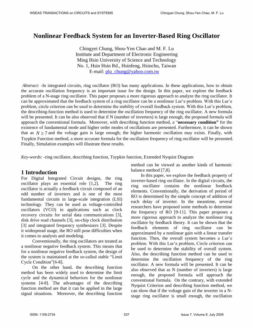
The SPICE simulation results are shown in Fig.17.SPICE gives a oscf of approximately 300 MHz [14].From describing function method of Eq.(25), we have
1tan( ) 301
2 (386 ) 3oscf MHzps
(58)
Also, by Tsypkin function of Eq.(43)-Eq.(45), we have1
2998.77(386 )oscf MHz
ps (59)
It can be observed that with Describing Function andTsypkin function methods, the predictions ofoscillation frequency are very accurate such that bothonly have (0.3%) errors. However, with theconventional formula, it has 15.6% error.
WSEAS TRANSACTIONS on CIRCUITS and SYSTEMS Chingyei Chung, Shou-Yen Chao, M. F. Lu
ISSN: 1109-2734 545 Issue 7, Volume 8, July 2009
Fig. 17. Simulation for a 5-stage Ring Oscillator(CN20 Process)
8 Conclusions & DiscussionsIn this paper, we proposed a rigorous approach
to analyze the nonlinear feedback of an inverter-basedring oscillator. It can be shown that the (RO) ringoscillator can be approximated by a nonlinear Lur’e problem. With this Lur’e problem, Circle criterion can be applied to determine the stability of overall system.A simple first-order RC delay model is used toapproximated by the model of the inverter.
The describing function method is used todetermine the oscillation frequency of the ringoscillator. A new formula is presented. It can beobserved that if N (number of inverters) is largeenough, the proposed formula will approach theconventional formula. Moreover, with extendedNyquist Criterion and describing function method, a“Necessary Condition”for the existence of oscillation(all modes) is shown as Eq.(34). It can be shown thatas 7N and the voltage gain is large enough, thehigher harmonic oscillation may exists. These resultscoincide with previous research reports [10][12]. Also,as 5N , the higher order harmonics will not exist .
On the other hand, with Tsypkin Functionmethod, a more accurate formula for the oscillationfrequency of ring oscillator will be presented. Finally,Simulation examples already have verified theseresults.
It should be further stress that the above resultscan be applied not only MOS transistor and can be alsoapplied to Bipolar transistor. Also, for a RO, thevoltage gain k should be large enough; otherwise, theoscillation doesn’t exist. In general, for the CMOS transistor the voltage gain is large enough since theoutput resistance (as seen in Eq.(13) )for NMOS and
PMOS transistors are very large. However, for NMOSinverters, the voltage gain may not be large enough[14,16]. Therefore, for a NMOS ring oscillator design,suitable channel length and width’s selection should be further investigated [14,16]. Also, in this paper, weonly address the ring oscillator with the number ofinverter N is odd. However, in some cases, even Nis even, the oscillation might be exist .AcknowledgementThe authors would like to thank the National ScienceCouncil for financial support under grants NSC 93-2218-E-159-001
References[1] Nell H. E. Weste and Kamran Eshraghian,
Principles of CMOS VLSI Design, 1998.[2] Thomas A. Demassa and Zack Cicone, Digital
Integrated Circuits, John Wiley & Sons, Inc 1996.[3] Lizhong Sun and Kwasniewski T. A., A 1.25-GHz
0.35- m Monolithic CMOS PLL Based on aMultiphase Ring Oscillators in 6H-SiC, IEEEJournal on Solid-State Circuits, Vol.36, No.6, Jun.2001.
[4] Chingyei Chung and J.L. Lin, A General Class ofSliding Surface for The Sliding Mode Control,IEEE Transactions on Automatic Control, 43,1998, pp.1509-1512.
[5] Chingyei Chung and J.L. Lin, A transformed lur'eproblem for the sliding mode control andchattering reduction, IEEE Trans. on AutomaticControl, 1999, 44, (3), 1999.
[6] J.E. Slotine, and Wei-ping Li, Applied nonlinearcontrol, Prentice-Hall, 1991 pp.159.
[7] M. Vidyasagar, Nonlinear system analysis,Prentice-Hall, 1994.
[8] P.A. Cook, Nonlinear dynamical systems, PrenticeHall, 1994.[9] Stephen Docking and Manoj Sachdev, A Method to
Derive an Equation for the Oscillation Frequencyof a Ring Oscillator, IEEE Transactions onCircuits and Systems-I: Fundamental Theory andApplications, Vol.50, No.2, Feb.2003
[10] Hatsuhiro Kato, A Dynamic Formulation of RingOscillator as Solitary-Wave Propagator, IEEETransactions on Circuits and Systems-I:Fundamental Theory and Applications, Vol.45,No.1, Jan. 1998
[11] M Alioto, and G.. Palumbo, Oscillation Frequencyin CML and ESCL Ring Oscillators, IEEETransactions on Circuits and Systems-I:
WSEAS TRANSACTIONS on CIRCUITS and SYSTEMS Chingyei Chung, Shou-Yen Chao, M. F. Lu
ISSN: 1109-2734 546 Issue 7, Volume 8, July 2009

Fundamental Theory and Applications, Vol.48,No.2, Feb. 2001
[12] N. Sasaki, Higher Harmonic Generation inCMOS/SOS Ring Oscillators, IEEE TransactionElectron Devices, Vol.ED-29, pp.280-283, Feb.1982.
[13] Arthur Gelb and Wallace E. Vander Velde,Multiple-Input Describing Functions andNonlinear System Design, McGraw-Hill BookCompany, 1968.
[14] R. Jacob Baker, Harry W. Li and David E. Boyce,CMOS Circuit Design, Layout and Simulation,John Wiley & Sons, Inc 1998.
[15] Sung-Mo Kang and Yusuf Leblebigi, CMOSDigital Integrated Circuits; Analysis and Design,McGraw-Hill Book Company, 1999.
[16] Ulrich Schmid and etc, High TemperaturePerformance of NMOS Integrated Inverters andRing Oscillators in 6H-SiC, IEEE Transactionson Electron Devices, Vol.47, No.4, Apr. 2000.
WSEAS TRANSACTIONS on CIRCUITS and SYSTEMS Chingyei Chung, Shou-Yen Chao, M. F. Lu
ISSN: 1109-2734 547 Issue 7, Volume 8, July 2009