nonlinear coherent magneto-optical response of a single chiral
TRANSCRIPT

Nonlinear coherent magneto-optical response of a single chiral carbon nanotube
This article has been downloaded from IOPscience. Please scroll down to see the full text article.
2010 New J. Phys. 12 103004
(http://iopscience.iop.org/1367-2630/12/10/103004)
Download details:
IP Address: 155.198.213.37
The article was downloaded on 15/10/2010 at 12:06
Please note that terms and conditions apply.
View the table of contents for this issue, or go to the journal homepage for more
Home Search Collections Journals About Contact us My IOPscience

T h e o p e n – a c c e s s j o u r n a l f o r p h y s i c s
New Journal of Physics
Nonlinear coherent magneto-optical response of asingle chiral carbon nanotube
G Slavcheva1,3 and Ph Roussignol2,3
1 Blackett Laboratory, Imperial College London, Prince Consort Road,London SW7 2AZ, UK2 Laboratoire Pierre Aigrain, Ecole Normale Supérieure, 24 rue Lhomond,75231 Paris Cedex 5, FranceE-mail: [email protected] and [email protected]
New Journal of Physics 12 (2010) 103004 (36pp)Received 17 May 2010Published 5 October 2010Online at http://www.njp.org/doi:10.1088/1367-2630/12/10/103004
Abstract. We propose a theoretical framework and dynamical model forthe description of the natural optical activity and Faraday rotation in anindividual chiral single-wall carbon nanotube (CNT) in the highly nonlinearcoherent regime. The model is based on a discrete-level representation of theoptically active states near the band edge. Chirality is modelled by a systemHamiltonian in a four-level basis corresponding to energy-level configurations,specific for each handedness, that are mirror reflections of each other. The axialmagnetic field is introduced through the Aharonov–Bohm and Zeeman energy-level shifts. The time evolution of the quantum system, describing a singlenanotube with defined chirality, under an ultrashort polarized pulse excitationis studied using the coupled coherent vector Maxwell-pseudospin equations(Slavcheva 2008 Phys. Rev. B 77 115347). We provide an estimate for theeffective dielectric constant and the optical dipole matrix element for transitionsexcited by circularly polarized light in a single nanotube and calculate themagnitude of the circular dichroism and the specific rotatory power in theabsence and in the presence of an axial magnetic field. Giant natural gyrotropy(polarization rotatory power ∼3000◦ mm−1 (B = 0 T)), superior to that of thecrystal birefringent materials, liquid crystals and comparable or exceeding thatof the artificially made helical photonic structures, is numerically demonstratedfor the specific case of a (5, 4) nanotube. A quantitative estimate of the coherentnonlinear magneto-chiral optical effect in an axial magnetic field is given
3 Authors to whom any correspondence should be addressed.
New Journal of Physics 12 (2010) 1030041367-2630/10/103004+36$30.00 © IOP Publishing Ltd and Deutsche Physikalische Gesellschaft

2
(∼30 000◦ mm−1 at B = 8 T). The model provides a framework for theinvestigation of the chirality and magnetic field dependence of the ultrafastnonlinear optical response of a single CNT.
Contents
1. Introduction 22. Problem formulation 63. Theoretical framework for description of the natural optical activity in a chiral
single-wall carbon nanotube (SWCNT) 94. Simulation results for the natural optical activity of an isolated SWCNT 145. Magneto-optical activity of a chiral SWCNT in an axial magnetic field 21
5.1. Theoretical model . . . . . . . . . . . . . . . . . . . . . . . . . . . . . . . . . 215.2. Simulation results for Faraday rotation . . . . . . . . . . . . . . . . . . . . . . 28
6. Conclusions 31Acknowledgments 32Appendix A. Effective dielectric constant of an isolated SWCNT 32Appendix B. Matrix element for dipole optical transitions excited by circularly
polarized light in a single SWCNT 33References 34
1. Introduction
The interaction of polarized light with chiral materials in the absence of magnetic fields givesrise to the phenomenon of optical (rotation) activity whereby the polarization plane is rotatedcontinuously during the light propagation across the medium. A simple phenomenologicaldescription of this effect, without considering the actual mechanisms involved, proposedby Fresnel, is based on circular double refraction, or the difference in phase velocity ofpropagation for the left- and right-circularly polarized light components. This, in turn, leads toa difference in refractive indices, and/or absorption for left- and right-circularly polarized light,which manifests itself as a circular birefringence, dichroism and rotatory power. Although thephenomenon of optical activity can be treated in terms of the classical electromagnetic theory,an in-depth understanding and full description of it requires a quantum-mechanical treatment ata microscopic level. The early molecular models were of two classes: two-particle models, e.g.the models of Born, Oseen [1], Kuhn [2] and Kirkwood [3] based on a spatial distribution ofcoupled oscillators, and single-oscillator models, e.g. the Drude helix model [4] and the Condon,Altar and Eyring theory [5] (for a comprehensive review, consult [6]). The first consistentquantum mechanical theoretical formalism was put forward by Rosenfeld without invoking thecouple oscillator model [7]. However, after Kuhn demonstrated that, when correctly treated, theDrude single-oscillator model does not exhibit rotatory power, the Drude model was forgotten.It has long been thought that the notion of coupled oscillators is a necessary condition for theexplanation of the rotatory power, until the Condon, Altar and Eyring model [5] demonstratedoptical activity using a quantum mechanical single-oscillator model. In the 1970s, however, itwas shown [8] that the Drude model exhibits optical activity in the nonlinear regime and recently
New Journal of Physics 12 (2010) 103004 (http://www.njp.org/)

3
it has been demonstrated that it leads to optical activity if the motion of the particle is treatedquantum mechanically [9].
The natural optical activity in chiral media, considered above, and the Faraday effect ofmagnetically induced optical activity both manifest themselves as a rotation of the polarizationof the transmitted light. However, the two effects are fundamentally different: while the naturaloptical activity is a result of a nonlocal optical response of a medium lacking mirror symmetry,the magnetic optical activity results from the breaking of the time-reversal symmetry by amagnetic field. The apparent similarity between the two effects has led to the theoreticalprediction and experimental demonstration [10] of the link between the two phenomenathrough the so-called magneto-chiral optical effect, which occurs under conditions when bothsymmetries are broken simultaneously.
Formulation of a theory and model of the optical activity in chiral molecules, such as theindividual single-wall carbon nanotubes (SWCNTs), in the high-intensity nonlinear coherentregime and under an axial magnetic field, which is the subject of this paper, is of special interestfrom a fundamental point of view. To the best of our knowledge, no such theory has beenproposed and very little is known about the polarization dynamics of the nonlinear opticaland magneto-optical response of a single CNT. A detailed understanding of the mechanismsunderlying the optical and magneto-optical birefringence, circular dichroism and rotation inthe nonlinear coherent regime opens up pathways for the development of a novel class ofultrafast polarization-sensitive optoelectronic devices, e.g. ultrafast optical switches, polarizers,etc, based on single CNTs as basic functional components of an integrated optoelectronicdevice.
In the quantum theory of the optical activity, one may distinguish two distinct classesof optically active molecules: a few molecules are inherently asymmetric, and the majorityof the molecules owe their activity to the asymmetric juxtaposition of symmetric (inherentlyoptically inactive) subsystems. Both mechanisms should be considered in a full treatment of themolecular optical activity model [11]. In what follows, we shall consider single objects ratherthan ensembles of CNTs and the chiral symmetry results from the inherent spiral alignment ofthe C-atoms in a single SWCNT.
Chirality is one of the main symmetries of the CNT geometry that determines the opticalproperties of the SWCNTs [12]. Investigation of the magneto-optical phenomena in chiralnanotubes is of considerable interest for nonlinear optical spectroscopy since it providesimportant information about their electronic structure [13]–[17].
Magnetic circular dichroism (MCD) and magneto-optical rotatory dispersion (MORD)techniques offer spectroscopic information that is different or impossible to obtain by othermeans. The magneto-optic Faraday effect and the time-resolved Faraday rotation technique inparticular [18] allow the measurement of the optically driven spin dynamics in semiconductornanostructures on an ultrafast time scale and with high spatial resolution. The study of the spindynamics in single CNTs is of particular interest in view of the potential integration of CNTs infuture spin devices.
Another motivation for the present study is that the chiral materials are of interest on theirown as they exhibit negative refractive index in a given frequency range and are promisingcandidates for metamaterial applications. Metamaterials consisting of helical structures havelong been recognized as promising candidates in the microwave range. However, for applica-tions working in the visible range, the helical structures should be down-scaled to nanometresize and therefore natural candidates could be sought at a molecular level. In fact, it has been
New Journal of Physics 12 (2010) 103004 (http://www.njp.org/)

4
demonstrated that some helical molecules show strong optical activity [19]–[24]. Recently, giantoptical gyrotropy in the visible and near-infrared (IR) spectral ranges, of up to 2500◦ mm−1, hasbeen demonstrated in artificial gyrotropic chiral media, in view of implementations as photonicchiral negative index metamaterials [25]. In this respect, it would be of great interest to assessthe magnitude of the natural and Faraday optical rotation in single CNTs as one-dimensional(1D) helical molecules under resonant coherent optical excitation, and to compare it with oneof the other candidates for metamaterials working in the visible range.
A theoretical framework for discussion of the optical activity [26] and Faraday rotationphenomena [27] in CNTs has been proposed within the tight-binding (TB) formalism. Analternative simplified TB approach was originally proposed by Romanov and Kibis [28] anddeveloped further in [29, 30]. Within this semiclassical approach, which, in what follows, wewill refer to as the Slepyan et al approach, the lowest conduction band energy spectrum iscalculated using the so-called spiral model: a phenomenological analytical method based onWannier formulation for the Schrödinger equation in a curvilinear coordinate system for ananotube, modelled by a chain of atoms wrapped helically around a cylinder, thereby accountingfor the helicoidal symmetry. The Wannier equation, in conjunction with the Boltzmann kineticequation, has been used to describe the nonlinear and chiral effects in the electron transporton the nanotube surface in an external rapidly oscillating (ac) and constant (dc) fields. Inparticular, surface wave propagation has been demonstrated and the possibility of exploitingCNTs as waveguides in the IR range has been discussed. This model, however, does not takeinto account the hexagonal lattice of the underlying graphene sheet and the transverse motionquantization. A full quantum-mechanical treatment, including the hexagonal lattice and thetransverse quantization, is given in [31], along with a detailed comparison with the spiral model.The comparison shows that the spiral model represents an adequate description of large-radiusCNTs and, due to its analytical tractability, can be useful for qualitative estimates.
It is worth noting that although chirality-induced nonlinear effects are the subject of boththe present work and the above cited works, we are interested not in the electronic transportand surface plasmon effects but rather in CNT dielectric properties under resonant coherentoptical pulsed excitations. To the best of our knowledge, the way the chirality affects thepolarization dynamics of the ultrafast nonlinear optical response of a single nanotube and themagnitude of this effect without and in an external magnetic field have not been investigated,and this is precisely the aim of the present study. We emphasize that both our approach andthe spiral model are semiclassical, but in a different way. In the case of the spiral model,the classic Boltzmann equation is coupled to the quantum Wannier equation, while within thepresent approach the electromagnetic wave propagation is treated classically using Maxwell’sequations, whereas the quantum system dynamics are treated quantum mechanically, using theLiouville equation. Most importantly, the two approaches are similar in the following. Unlikeother theories [28, 41], both approaches do not consider the interference between the axial andhelical paths (or equivalently, the axial and transverse wavevectors coupling) as the origin of thechirality effects. The spiral model provides a 1D periodic (zero field) electron dispersion lawwith periodic energy dependence on the electromagnetic field and predicts a uniform shift ofthe positions of the periodic minima in the dispersion when a magnetic field is applied.
In this paper, we develop a dynamical model for the ultrafast circularly polarized lightpulse interaction with single chiral SWCNTs in the absence and in the presence of an externalmagnetic field, which allows for assessing the magnitude and ellipticity of this rotation. Indistinction with the spiral model, discussed above, the transverse quantization of motion is taken
New Journal of Physics 12 (2010) 103004 (http://www.njp.org/)

5
into account within our approach through the subband structure, and the energy dispersion alongthe nanotube axis is approximated by a constant. This simplification is justified by the followingarguments: (i) the specific CNT geometry considered, namely the CNT length (500 nm), ismuch greater than the unit cell length (T = 3.32 nm), as inferred from TB calculations (fordetailed discussion, please refer to section 3 and appendix B), which allows one to approximatethe periodically modulated lowest subband edges along the nanotube axis by a discrete-levelsystem; (ii) relatively flat curvature of the lowest-lying subbands as compared to the curvatureof the higher-lying subbands; in particular, the lowest-lying subbands in the (5, 4) nanotube,considered for illustration, are considerably flat (horizontal), to allow for this approximation;(iii) the resonant character of the optical excitations in the vicinity of K (K ′) point of theBrillouin zone (BZ) (or equivalently, at the 0 point in the centre of the first one-dimensionalBZ, when the zone-folding technique is applied) where the fundamental bandgap of theCNT actually occurs. It should be noted that we are interested in near-bandgap excitations,close to the energy dispersion minimum, where both the method of Slepyan et al and oursconverge, providing the level of description relevant to the resonant absorption/amplificationprocesses considered. We thus believe that our simplified model successfully captures the mostimportant features of the dynamics of the resonant optical excitation and interaction with thenanostructure. We should note that the model could be extended to include the full dispersionby introducing a set of four-level systems with appropriate (for each value of the wavevectoralong the tube axis) separation between the levels and oscillator strength for the correspondinginterlevel transitions.
Another important feature of the CNT response to femtosecond laser pulses is the coherentphonon generation. The lattice dynamics of a CNT following a femtosecond optical pulseexcitation has been studied by molecular dynamics simulations coupled to a TB descriptionof the CNT [64]. The employed semiclassical technique accounts for the quantum evolutionof the electronic system in an external laser field, whereas the lattice ions motion is describedclassically, using a thermodynamic formulation. As a result of the electronic excitation, threecoherent breathing phonon modes are excited: two radial vibrations localized in the caps and thetubular body, and one longitudinal vibration coupled to the nanotube length. It has been shownthat at sufficiently high (but still below graphite’s ultrafast fragmentation threshold) absorbedenergies, the oscillations lead to opening of the nanotube caps, while the tubular body remainsintact on a picosecond time scale. Although our model does not provide a description of thelattice dynamics under a resonant ultrafast optical pulse, the discussed effects might prove quitesignificant. We should note that the excitation fluence assumed in our computations is of theorder of 2–20 µJ cm−2 (corresponding to 60–150 fs pulse duration, see appendix B), whichis several orders of magnitude lower than the fluences used in [64] of the order of hundredsof mJ cm−2 (corresponding to a 10 fs pulse duration). Taking into account the uncertainty inthe fluences in the latter work, estimated using graphite data, we cannot rule out that capopening could occur as a result of the ultrashort pulse excitation. We emphasize, however,that the numerical simulations in [64] demonstrate that the cylindrical body of the nanotubeis not affected within reasonably long time intervals, of the order of the simulation times inour computations (long after the pulse passage across the nanostructure), and optical rotation inchiral nanotubes would still be possible.
Our theoretical and numerical approach follows the general Maxwell-pseudospinformalism developed in an earlier publication [38] for the description of the ultrafast coherentcarrier dynamics of a discrete-level quantum system in an external dipole coupling perturbation.
New Journal of Physics 12 (2010) 103004 (http://www.njp.org/)

6
The new components of the model comprise (i) the specific lowest energy-level configurationadopted for a description of the two helical forms of the nanotube; (ii) inclusion of the CNTrelaxation dynamics, identifying the allowed interband dipole optical transitions and intrabandrelaxation and dephasing (including the specific time scales); (iii) introduction of an externalmagnetic field in the system Hamiltonian through the resonant transition energy and the specificenergy-level configuration in an axial magnetic field, taking into account the Zeeman splittingof the energy levels and Aharonov–Bohm (AB) phase shift; (iv) provision of an estimate for theCNT dielectric response function and dipole moment matrix element for transitions excited bycircularly polarized light.
The paper is organized as follows. In section 2, we formulate the problem of ultrashortcircularly polarized pulse propagation and resonant coherent interactions in an isolatedSWCNT. In section 3, we provide a theoretical framework for tackling the resonant nonlinearabosrption/amplification in chiral CNTs based on band-edge energy-level configurationsspecific for left- and right-circularly polarized optical excitation. The proposed dynamical modelfor description of the ultrafast optically induced dynamics requires both a knowledge of thedielectric response function and the optical dipole matrix element for optical transitions excitedby circularly polarized light in a single SWCNT. The calculation of these model parametersis given in appendices A and B, respectively. In section 4, we present the simulation resultsfor the ultrafast nonlinear dynamics of the natural optical activity in a single chiral SWCNTand calculate the time- and spatially resolved circular dichroism, birefringence and specificrotatory power for a particular (5, 4) nanotube geometry. In section 5, we develop a model ofthe nonlinear Faraday rotation in an axial magnetic field in a chiral SWCNT, including both theenergy-level shift due to the AB flux and the spin-B interaction, resulting in Zeeman splittingof the energy levels near the bandgap. We provide an estimate for the spatially resolved MCDand specific rotatory power along the tube length following the initial pulse excitation. Finally,in section 6, we give a summary of the results and outline some future model applications.
2. Problem formulation
SWCNTs are uniquely determined by the chiral vector, or equivalently by a pair of integernumbers (n, m) in the planar graphene hexagonal lattice unit vector basis. A primaryclassification of CNTs is the presence or absence of the chiral symmetry. Achiral nanotubes,whose mirror image is superimposable, are subdivided into two classes: zigzag (m = 0) andarmchair (m = n) nanotubes. The rest of the nanotubes belong to the most general class ofchiral nanotubes, whose mirror reflection is not superimposable.
Chiral molecules exist in two forms that are mirror images of each other (enantiomers).Similarly, CNTs exist in two left-(AL) and right-(AR) handed helical forms depending on therotation of two of the three armchair (A) chains of carbon atoms counterclockwise or clockwisewhen looking against the nanotube z-axis. The two helical forms are shown for illustration for a(5, 4) and a (4, 5) SWCNT in figure 1, where we have adopted the following convention: m > ncorresponds to a left-handed (AL) nanotube, whereas m < n corresponds to a right-handed (AR)nanotube.
The electronic band structure of an SWCNT [32] is described by the quantization of thewavevector along the tube circumference, perpendicular to the tube axis, resulting in a discretespectrum of allowed k-vector states forming subbands in the valence and conduction bandslabelled by the quasi-angular momentum quantum number (µ).
New Journal of Physics 12 (2010) 103004 (http://www.njp.org/)

7
Figure 1. An illustration of the single CNT molecular structure of (a) left-handedAL (5, 4) and (b) right-handed AR (4, 5) single SWCNTs calculated using theTB method of Pz-orbitals [36]: a view along the tube axis against the z-axisdirection.
In what follows, we shall consider aggregates or bundles of aligned SWCNTs [33], grownby chemical vapour deposition in an electric field [34], or aligned in a polymer matrix. Whena circularly polarized (in the x–y plane) laser pulse propagates along the z-axis of an AL orAR SWCNT (figure 2(a)), only one of the two allowed transitions for a linearly polarizedlight (along x or y), between the quasi-angular momentum subband states µ → µ − 1 andµ → µ + 1, can be excited [35] (figure 2(b)). Here we adopt the following convention for opticalpulse polarization: the left (σ−
= x − iy) and right (σ += x + iy) helicity of light corresponds to
counterclockwise and clockwise rotation of the electric field polarization vector when lookingtowards the light source (against the z-axis direction).
We model the single chiral nanotube band-edge structure at the K point of the BZ by anensemble of a large number of identical four-level systems, corresponding to the dipole opticallyallowed transitions for AL and AR nanotube enantiomers. As has been pointed out in [35],taking into account the polarization sense convention above, absorption of right-circularlypolarized light σ + excites the electronic transitions µ − 1 → µ, or equivalently µ → µ + 1in AL-handed SWCNTs and µ → µ − 1 transitions in AR-handed SWCNTs, whereas theabsorption of left-circularly polarized σ− light excites µ → µ − 1 transitions in AL-handedSWCNTs and µ → µ + 1 transitions in AR-handed SWCNTs (figure 3).
Note that the chiral symmetry of the medium is incorporated at a microscopic levelthrough the energy-level scheme and the allowed dipole optical transitions for AL- andAR-handed SWCNTs: the mirror reflections of the two energy-level configurations cannot besuperimposed. The origin of the optical activity is the difference in optical selection rules forleft- and right-circularly polarized light and the specific relaxation channels involved at opticalexcitations with each polarization sense and their respective time scales [37].
The adopted discrete four-level system approximation of the CNT band structure is agood approximation at or in the vicinity of the K (K ′) point of the Brillouin zone wherethe fundamental bandgap of the CNT actually occurs. Furthermore, since we consider onlyresonant, or near-resonant, laser excitations, the optically active states near the band edge aremore likely to be involved in the dynamics. This is the reason why we consider the minima oftwo conduction and two valence subbands closest to the Fermi level. We reiterate that despite
New Journal of Physics 12 (2010) 103004 (http://www.njp.org/)

8
(a)
(b)
Figure 2. (a) Geometry of an experiment with an optical excitation by a circularlypolarized pulse propagating along the SWCNT axis; Ex and Ey are the Cartesiancomponents of the E-field vector; (b) 1D electronic density of states (DOS)versus energy at the K point of the BZ (µ > 0) of an AL-handed (20, 10) chiralSWCNT. The allowed dipole optical transitions for circularly polarized light aredesignated by arrows for left- (σ−) and right- (σ +) pulse helicity.
our description not including the π -electrons energy dispersion along kz, in view of the resonantexcitation considered, we select and access specifically the minima of the conduction/valencesubbands closest to the band edge by tuning the optical pulse centre frequency in resonancewith the circularly polarized transition frequency. In fact, although the ultrashort (60 fs) is a
New Journal of Physics 12 (2010) 103004 (http://www.njp.org/)

9
Figure 3. Energy-level structure at the K (K ′) point of the lowest subbandslabelled by the subband index µ for (a) AL-handed and (b) AR-handedSWCNTs. The fundamental energy gap is shaded. ω0 is the resonant transitionfrequency and 1 is the energy separation between the lowest subband and thesecond lowest subband near the band gap. The dipole optical transitions excitedby σ− and σ + circularly polarized light are designated by arrows. Only one ofthe two transitions is allowed for circularly polarized light, denoted by a solid(dashed) arrow. Valence band states below the bandgap are populated.
broadband pulse, its spectral width is ∼10 meV, which does not change the resonant characterof the excitation (see figure 4). We do not expect drastic changes when the kz-dispersion isincluded, primarily due to the (i) resonant excitations at the K point used and, in the specificcase of a (5, 4) nanotube considered, (ii) relatively flat (horizontal) lowest-lying subbands ascompared to the curvature of the higher-lying subbands (see figure 4(a)). Although this flatlowest subbands property cannot be applied to all chiral nanotubes, as is demonstrated bythis particular (5, 4) nanotube, certain nanotubes exhibit these characteristics, thus enablingengineering of chirality with the aim of achieving larger rotation angles and stronger opticalactivity. This is the purpose of the specific case considered for illustration.
3. Theoretical framework for description of the natural optical activity in a chiralsingle-wall carbon nanotube (SWCNT)
The proposed theoretical model is based on the self-consistent solution of Maxwell’sequations in vectorial form for the polarized optical pulse propagation and the time-evolutionpseudospin equations of the discrete multi-level quantum system in the external time-dependentperturbation [38]. This is a semiclassical approach that treats the optical wave propagationclassically through Maxwell’s equations and therefore requires knowledge of the effectivedielectric constant of the medium. On the other hand, the quantum evolution equations requireknowledge of the dipole optical transition matrix element for transitions excited by circularlypolarized light in a single CNT. We give an estimate of these important model parameters inappendices A and B for the specific case of a chiral AL-handed (5, 4) SWCNT, which is chosenfor illustration of the general method valid for an arbitrary chirality.
New Journal of Physics 12 (2010) 103004 (http://www.njp.org/)

10
Figure 4. (a) Energy dispersion versus longitudinal (along the tube axis)wavevector kt , normalized with respect to the wavevector at the boundary ofthe BZ ktmax of a (5, 4) SWCNT; (b) 1D-DOS versus energy showing thelowest energy subbands near the band edge involved in dipole optical transitionsinduced by circularly polarized light. Only one transition can be excited at anyone time by each helicity (σ− or σ +).
We shall assume a nanotube of length Ln = 500 nm. In what follows, the finite-size edgediffraction effects are ignored since our model is quasi-1D and it is unrealistic to implementedge diffraction or capped CNT geometries in 1D. The main goal of the study is to provide atheoretical estimate for the rotatory power per unit length, due to the specific helical arrangementof the atoms, and to demonstrate the possibility of manipulating the optical rotation throughthe nanotube geometry. On the other hand, recent studies [64] of the response of CNTs tofemtosecond laser pulses point out the possibility of the fragmentation, release and opening ofthe nanotube caps, due to the generation of coherent breathing phonons. Therefore, it is realisticto ignore the edge effects under ultrashort pulsed excitations. We should note that at least a 2Dmodel is required to account for the edge diffraction effects.
TB calculations [36] provide the electronic band structure (figure 4), namely thefundamental bandgap Eg = Eµ,µ = 1.321 eV, corresponding to a wavelength λ = 939 nm,nanotube diameter d = 0.611 nm and chiral angle θ = 26.33◦. The resonant transition energy forcircularly polarized excitations is Eµ,µ±1 = 1.982 eV, corresponding to a resonant wavelengthλ0 = 626.5 nm.
Consider an ultrashort circularly polarized pulse in the (x–y) plane propagating along thenanotube z-axis, resonantly coupled to an ensemble of identical homogeneously broadenedfour-level systems describing the resonant absorption/amplification in a single CNT (figure 5).
New Journal of Physics 12 (2010) 103004 (http://www.njp.org/)

11
Figure 5. Energy-level diagram in the general case of a resonant opticalexcitation of µ → µ + 1 and µ → µ − 1 interband transitions by σ + and σ−
polarized pulses, respectively. The resonant transition energy is hω0. 1 is theenergy separation between the first and second lowest conduction (valence)band states. The initial population of the lowest valence states below thebandgap, ρ11i and ρ33i , is equally distributed between levels |1〉 and |3〉. Allallowed longitudinal relaxation processes between the levels, associated withpopulation transfer, are designated by wavy lines. 01 is the spontaneous emission(radiative decay) rate of the interband transition |2〉 → |1〉, which, owing to thesymmetry, is assumed equal to the spontaneous emission rate of |4〉 → |3〉; 02
is the spontaneous emission rate for the µ → µ transition allowed for linearlypolarized light; 03 is the decay rate of the µ − 1 → µ − 1 linearly polarizedtransition and γ is the intraband relaxation rate. The transverse relaxation(dephasing) rates 0µ and 0µ−1 are designated by arrows.
Following the coherent Maxwell-pseudospin formalism developed in [38], the generic systemHamiltonian in the four-level basis that applies to an excitation with either σ− or σ + light helicityis written, at resonance, as
H = h
0 −
12
(�x + i�y
)0 0
−12
(�x − i�y
)ω0 0 0
0 0 1 −12
(�x − i�y
)0 0 −
12
(�x + i�y
)1 + ω0
, (1)
where �x = ℘(Ex/h) and �y = ℘(Ey/h) are the time-dependent Rabi frequencies associatedwith Ex and Ey electric field components and ℘ is the optical dipole matrix element forµ → µ ± 1 transitions excited by circularly polarized light (calculated in appendix B).
The time evolution of the quantum system under an external dipole-coupling perturbationin the presence of relaxation processes (figure 5) is governed by a set of pseudospin master
New Journal of Physics 12 (2010) 103004 (http://www.njp.org/)

12
equations for the real state 15-dimensional vector S derived in [38],
∂S j
∂t=
{f jklγk Sl + 1
2Tr(σ λ j) −1T j
(S j − S je), j = 1, 2, . . . , 12,
f jklγk Sl + 12Tr(σ λ j), j = 13, 14, 15,
(2)
where γ is the torque vector, f is the fully antisymmetric tensor of the structure constantsof SU(4) group, and T j are the phenomenologically introduced non-uniform spin decoherencetimes describing the relaxation of the real state vector components S j toward their equilibriumvalues S je. Using the generators of the SU(4) Lie algebra, the following expression for thetorque vector is obtained,
γ =
(−�x , 0, 0, 0, 0, −�x , �y, 0, 0, 0, 0, −�y, ω0,
21 − ω0√
3,
√2
3(1 + ω0)
). (3)
In equation (2), similar to [39], we have introduced a diagonal matrix σ = diag(Tr(0i ρ)),i = 1, . . . , 4, where ρ is the density matrix of the system, accounting for the longitudinalrelaxation accompanied by population transfer between the levels. Defining the matrices 0i ,
01 =
0 0 0 0
0 01 0 0
0 0 γ 0
0 0 0 03
, 02 =
0 0 0 0
0 − (01 + 02) 0 0
0 0 0 0
0 0 0 γ
,
03 =
0 0 0 0
0 02 0 0
0 0 −γ 0
0 0 0 01
, 04 =
0 0 0 0
0 0 0 0
0 0 0 0
0 0 0 − (01 + 03 + γ )
,
(4)
σ -matrix components can be expressed in terms of the real state vector as
σ11 =1
12
(2√
3S14 (2γ − 01) −√
6S15 (γ + 01 − 303) + 3 (γ + 01 + 2S1301 + 03))
,
σ22 =1
12
(3γ(
1 +√
6S15
)+(−3 − 6S13 + 2
√3S14 +
√6S15
)(01 + 02)
),
σ33 =1
12
(√6S15 (γ + 301 − 02) − 2
√3S14 (2γ + 02) + 3 (−γ + 01 + 02 + 2S1302)
),
σ44 = −14
(1 +
√6S15
)(γ + 01 + 03) .
(5)
The introduction of a dephasing matrix 0t , accounting for the dissipation in the system dueto polarization relaxation,
0t =
0 0µ 0µ 0µ−1
0µ 0 0µ 0µ−1
0µ 0µ 0 0µ−1
0µ−1 0µ−1 0µ−1 0
, (6)
implies transverse relaxation (dephasing) times in the first term of equation (2) given byT1 = T2 = T3 = T7 = T8 = T9 = 1/0µ and T4 = T5 = T6 = T10 = T11 = T12 = 1/0µ−1.
New Journal of Physics 12 (2010) 103004 (http://www.njp.org/)
13
Expressions for the longitudinal population relaxation times T13, T14 and T15 are derivedthrough the second term in equation (2), giving
T13 =4
201 + 02, T14 =
4
2γ + 02, T15 =
2
γ + 01 + 03. (7)
Within the coherent master Maxwell-pseudospin equations approach [38], the 1DMaxwell’s curl equations for the circularly polarized laser pulse propagating in an isotropicmedium with effective dielectric constant ε (calculated in appendix A),
∂ Hx(z, t)
∂t=
1
µ
∂ Ey(z, t)
∂z,
∂ Hy(z, t)
∂t= −
1
µ
∂ Ex(z, t)
∂z,
∂ Ex(z, t)
∂t= −
1
ε
∂ Hy(z, t)
∂z−
1
ε
∂ Px(z, t)
∂t,
∂ Ey(z, t)
∂t=
1
ε
∂ Hx(z, t)
∂z−
1
ε
∂ Py(z, t)
∂t,
(8)
are solved self-consistently with the pseudospin equations (2). The two sets of equations arecoupled through the macroscopic polarization induced in the medium by the circularly polarizedelectromagnetic wave. We derive the following relations between the medium polarizationvector and the real state vector components,
Px = −℘Na(S1 + S6),
Py = −℘Na(−S7 + S12),(9)
where Na is the density of the ensemble of resonantly absorbing/amplifying four-level systems.These polarizations act as source terms in the vector Maxwell’s equation for the optical wavepropagation equation (8).
The above set of equations (8), (2) and (9) is solved numerically for the fields and the real-vector components in the time domain employing the finite-difference time-domain (FDTD)technique without invoking any approximations, such as slowly varying wave approximation(SVEA) and rotating wave approximation (RWA).
The initial circularly polarized optical pulsed excitation, applied at the left boundary of thesimulation domain z = 0 (figure 6), is modelled by two orthogonal linearly polarized opticalwaves, phase-shifted by π/2,
σ−
{Ex (z = 0, t) = E0 e−(t−t0)2/t2
d cos(ω0t),
Ey (z = 0, t) = −E0 e−(t−t0)2/t2d sin(ω0t),
σ +
{Ex (z = 0, t) = E0 e−(t−t0)2/t2
d cos(ω0t),
Ey (z = 0, t) = E0 e−(t−t0)2/t2d sin(ω0t),
(10)
where E0 is the initial field amplitude; the pulse carrier frequency is tuned in resonance withthe dipole optical transition frequency ω0 and is modulated by a Gaussian, centred at t0 withcharacteristic decay time td, which determines the pulse duration. A linearly polarized pulse
New Journal of Physics 12 (2010) 103004 (http://www.njp.org/)

14
Figure 6. Simulation domain: the isolated SWCNT with length Ln = 500 nm isplaced between two free space regions, each 50 nm long. The source pulse startsto propagate from the left boundary z = 0.
along the x (y) direction is modelled by
X
{Ex (z = 0, t) = E0 e−(t−t0)2/t2
d cos(ω0t),
Ey (z = 0, t) = 0,
Y
{Ex (z = 0, t) = 0,
Ey (z = 0, t) = E0 e−(t−t0)2/t2d sin(ω0t).
(11)
4. Simulation results for the natural optical activity of an isolated SWCNT
The simulated semiconducting (5, 4) AL-handed SWCNT structure with effective refractiveindex n = 2.3 (see appendix A) is shown in figure 6 embedded between two free space (air)regions with refractive index n = 1. The simulation domain is finely discretized in space with1z = 1 nm, which, through the Courant numerical stability criterion, corresponds to a time stepof 1t = 3.34 × 10⁻¹⁸ s.
The ultrashort optical pulse with pulse duration τ = 60 fs (selected to match theexperimental conditions in [37]) and Gaussian envelope is injected from the left boundary(z = 0). The pulse centre frequency ω0 = 3.01 × 10¹⁵ rad s−1 is tuned in resonance with theenergy splitting between µ → µ ± 1 subband states of Eµ,µ±1 ∼1.982 eV, corresponding toa wavelength λ = 626.5 nm. Since we are interested in the high-intensity nonlinear regime,throughout the simulations the pulse area below the pulse envelope is chosen to be π , givingan initial electric field amplitude E0 = 6.098 × 10⁸ V m−1 (see equation (10)). A π -pulse is ofparticular interest since it completely inverts the population in a two-level system.
In order to ensure that our ensemble approach describes properly the single nano-object,we select the density of the coupled oscillators, described by four-level systems, in such a waythat the simulated nanotube volume (with diameter d = 0.611 nm and length Ln = 500 nm)contains, on average, only one carbon nanotube [38]. This yields an average density Na =
6.811 × 1024 m−3 of resonant absorbers.The ultrafast optically induced polarization dynamics depend very strongly on the
phenomonological relaxation rates. Assuming the value ℘ = 3.613 × 10⁻²⁹ Cm for the opticaldipole matrix element calculated in appendix B, we use the expression for the spontaneousemission rate [40], taking into account the corresponding energy separation for each transition,
New Journal of Physics 12 (2010) 103004 (http://www.njp.org/)

15
Figure 7. Time evolution of the electric field vector components Ex , Ey andthe populations of all four levels in figure 5 under right-circularly polarizedoptical pulse excitation σ + at four different locations along the nanotube axis((a) z = 175 nm; (b)z = 300 nm; (c) z = 425 nm; (d) z = 550 nm) measured fromthe left boundary z = 0 in figure 6. The initial population is assumed equallydistributed between the lower-lying levels |1〉 and |3〉: ρ11i = ρ33i = 1/2. Level|4〉 is not involved in the dynamics.
to obtain an estimate for the relaxation rates. Thus, we obtain the following parameters:01 = 2.907 ns−1, 02 = 9.812 ns−1, 03 = 1.227 ns−1. We take the experimental value obtainedin [37] for the intraband optical transitions, namely γ = 130 fs−1. Since the dephasing ratesfor the states involved are largely unknown, we treat them as phenomenological parameters,adopting the following values: 0µ = 800 fs−1 and 0µ−1 = 1.6 ps−1. We should note that wehave performed a number of simulations with different values of dephasing times varyingwithin a fairly wide range (from fs to hundreds of ps), which confirmed that the spatio-temporaldynamics, and consequently the model predictions concerning the circular dichroism and opticalrotation, are to a great extent insensitive to the choice of 0µ and 0µ−1.
Throughout the simulations, the population density of all four levels is conserved (ρ11 +ρ22 + ρ33 + ρ44 = 1). We consider separately the two cases of an ultrafast resonant opticalexcitation of the |1〉 → |2〉 transition with σ + helicity and of the |3〉 → |4〉 transition with σ−
helicity (figure 5). Note that in the former case, level |4〉 does not participate in the relaxationdynamics and the system is effectively a three-level 3-system, rather than a four-level system.
New Journal of Physics 12 (2010) 103004 (http://www.njp.org/)

16
The ultrashort circularly polarized source pulse is injected into the medium and the temporaldynamics of the electric field vector components and population of all four levels are sampledat four different locations along the nanotube z-axis. The time evolution of the pulse E-fieldcomponents, normalized with respect to E0, or the pulse reshaping, and the level populations areshown in figure 7 for times immediately after the excitation. The initial pupulation is assumedequally distributed between the lower-lying levels (ρ11i = ρ33i = 1/2). The population of thelowest level |1〉, initially slightly increases due to the ultrafast population transfer from level |3〉
which is initially populated. The optical pulse excites the population to level |2〉: the populationof level |1〉 sharply decreases while at the same time the population of level |2〉 increases. Thepopulation of level |3〉 decays almost exponentially, since the pumping of this level throughpopulation relaxation from |2〉 is at a much slower rate (by three orders of magnitude) than theintraband relaxation rate. The pulse trailing edge is slightly distorted due to the dipole formedbetween levels |3〉 and |2〉 (at the intersection point between ρ22 and ρ33, figure 7), re-radiatingback to the field. It is obvious that the final population after very long simulation times willrelax to the equilibrium value ρ11e = 1 into level |1〉 (not shown on this time scale). During thepulse propagation along the nanotube, the pulse is undergoing resonant absorption and emission,resulting in pulse amplitude amplification, increasing from ∼0.6 near the left boundary to ∼0.8at the right structure boundary (figure 7(a) and (d)). This implies that the CNT behaves as a lasergain medium under an ultrashort circularly polarized pulsed optical excitation.
The system dynamics under σ− polarized optical excitation is quite distinct, since all fourlevels are involved in it (figure 8). As in the previous case, the initial population is assumedequally distributed between the lower-lying levels. The population residing in level |3〉 is partlyresonantly excited into level |4〉 by the passage of the pulse, shown by the sharp increase of ρ44
and a corresponding decrease of ρ33. The population of level |1〉 slowly increases, rather thansharply dropping (cf figure 7), due to population transfer by spontaneous emission, interband(µ − 1 → µ − 1) and intraband relaxation processes (figure 5). The population of level |2〉
increases at a slower rate during the passage of the pulse, due to depletion by the competingrelaxation channels, reaching a maximum at later times (not shown) and subsequentlydecreasing. Eventually, the whole population relaxes into the lowest-lying state |1〉. As in theprevious case considered, a slight pulse trailing edge distortion is observed, due to the formingof a dipole between levels |4〉 and |2〉 and between |3〉 and |2〉. Similar to the previous case, thepulse amplitude is amplified during the pulse propagation along the nanotube axis.
It is obvious that the different dynamics involved in the two cases of ultrafast opticalexcitation by σ + and σ− polarized pulses would lead to asymmetry of the optical propertiesand therefore to a circular dichroism, birefringence and optical rotation. In what follows, weshall evaluate quantitatively the magnitude of these chirality effects.
From an experimental point of view, it would be of particular interest to be able todistinguish between the spectra of the transmitted pulses at the output facet of the simulateddomain for each helicity of the ultrashort excitation pulse. The time traces of the Ex and Ey
electric field components of the input and transmitted pulses (at the output facet of the simulatedstructure, figure 6) and their respective Fourier spectra are shown in figure 9 for the case of anultrashort σ + polarized excitation. The transmission spectra exhibit a sharp peak at the resonantwavelength, which is an indication of resonant amplification. The corresponding time traces andFourier spectra for σ− polarized excitation are shown in figure 10. Similar to the previous case,the transmission spectrum exhibits a sharp resonant peak at the resonant wavelength. However,a comparison between figures 9 and 10 reveals nearly an order of magnitude higher intensity of
New Journal of Physics 12 (2010) 103004 (http://www.njp.org/)

17
Figure 8. Time evolution of the electric field vector components Ex , Ey andthe populations of all four levels in figure 5 under left-circularly polarizedoptical pulse excitation σ− at four different locations along the nanotube axis((a) z = 175 nm; (b) z = 300 nm; (c) z = 425 nm; (d) z = 550 nm) measuredfrom the left boundary z = 0 in figure 6.
the peak, corresponding to the σ + excitation. The difference in the ultrafast transient responsecan be exploited in an experiment aiming to unambiguously determine the chirality of a singleCNT by using ultrafast circularly polarized pulses of both helicities. In what follows, we shalldemonstrate that the difference in the polarization-resolved (along x and y) transmission spectraof a linearly polarized excitation is much more pronounced and permits the identification of theprecise helical form of the SWCNT.
In order to numerically demonstrate the rotation of the polarization plane during the pulsepropagation across the medium, a linearly polarized (along x) pulse (equation (11), first line)is injected. The system temporal dynamics induced by the ultrashort linearly polarized pulseis shown in figure 11. Note that on this scale a non-vanishing Ey component is not apparent;however, on an expanded scale (figure 12), the appearance of a second Ey component (cyanline), and therefore the optical rotation of the E-field vector polarization, is clearly visible.The amplitude of the Ey component continuously increases as the pulse propagates along thenanotube structure. We should therefore expect a maximum optical rotation angle at the outputfacet, as shown in figures 13(a) and (b). The transmitted pulse is elliptically polarized. Theoptical transmission spectra of the x-polarized and y-polarized electric field vector components
New Journal of Physics 12 (2010) 103004 (http://www.njp.org/)

18
(a)(b)
(d)(c)
Figure 9. (a) Time trace of the Ex component of the input Ex(0) (solid blue line)and output Ex(L) (solid red line) σ + polarized pulse. (b) Transmission (Fourier)spectra versus wavelength of the input (blue line) and output (red line) σ + pulses.(c) Time trace of the Ey component of the input Ey(0) (blue line) and outputEy(L) (red line) σ + polarized pulse. (d) Transmission spectra versus wavelengthof the input (blue line) and output (red line) pulses.
are quite distinct: while the former exhibits a sharp resonant peak superimposed on a broaderline, the latter exhibits a single spectral line centred at the resonant wavelength.
In order to obtain a quantitative estimate of the natural optical activity in a single chiralCNT, we calculate the average absorption/gain coefficient and phase shift induced by theresonant medium from the real and imaginary parts of the complex propagation factor eikc(z2−z1)
for the Ex and Ey electric field components, over a distance of one dielectric wavelengthl = z2 − z1 = λ0/n, where λ0 is the resonant wavelength. The wavevector kc = β + iγ , where β
is the phase shift per unit length in the optical pulse induced by the interaction with the resonantmedium and γ is the absorption/gain coefficient. The absorption/gain coefficient allows us tocalculate the magnitude of the circular dichroism and the phase shift represents a measure ofthe rotation angle.
We select four pairs of points z along the nanotube length with staggered distances fromthe left boundary (z = 0) within the CNT structure, separated by one dielectric wavelength,and calculate the above quantities for each pair. The plots in figure 14 show a comparisonbetween the gain coefficients for σ + excitation, corresponding to pumping |1〉 → |2〉 transition,and for σ− excitation, corresponding to pumping |3〉 → |4〉 transition in figure 5. The theoretical
New Journal of Physics 12 (2010) 103004 (http://www.njp.org/)

19
(a) (b)
(d)(c)
Figure 10. (a) Time trace of the Ex component of the input Ex(0) (solid blueline) and output Ex(L) (solid red line) σ− polarized pulses. (b) Transmission(Fourier) spectra versus wavelength of the input (blue line) and output (red line)σ− pulses. (c) Time trace of the Ey component of the input Ey(0) (blue line) andoutput Ey(L) (red line) σ− polarized pulses. (d) Transmission spectra versuswavelength of the input (blue line) and output (red line) pulses.
gain coefficient of a homogeneously broadened two-level system is shown on the same plotfor reference. The difference between the two plots at the resonant wavelength gives us anestimate of the magnitude of the natural circular dichroism in the (5, 4) CNT. The spatiallyresolved circular dichroism along the nanotube axis is calculated from the difference betweenthe maxima of the gain coefficients at the resonant wavelength, corresponding to excitationwith the two helicities (R or σ +) and (L or σ−): 1A = GR − GL at each location (see figure 14),giving an average of 0.083 µm−1.
An estimate for the circular dichroism of a (5, 4) nanotube can be calculated from [41],equation (44), giving a value of 1.03 for the relative difference between σ + and σ− absorptionprobability rates. This value, however, cannot be directly compared with the obtained resultsince the nanotube length does not enter the model in [41], and thus can only serve as a guide.We should stress that our analysis applies to the high-intensity nonlinear ultrafast regime, inwhich, to the best of our knowledge, no theory or experiments have been published. Therefore,we could expect deviations from the linear case. By comparison, the absolute value of thecircular dichroism of an artificial helicoidal bilayered structure varies in the range of 5–9 dB,which is equivalent to a linear amplitude absorption/gain coefficient range fo 0.58–1.04 µm−1.
New Journal of Physics 12 (2010) 103004 (http://www.njp.org/)

20
(a) (b)
(d)(c)
Figure 11. Time evolution of the electric field vector components Ex and Ey andthe populations of all four levels in figure 5 under linearly polarized optical pulseexcitation at four different locations along the nanotube axis ((a) z = 175 nm;(b) z = 300 nm; (c) z = 425 nm; (d) z = 550 nm) measured from the leftboundary z = 0 in figure 6. The initial population is assumed equally distributedbetween the lower-lying levels |1〉 and |3〉: ρ11i = ρ33i = 1/2.
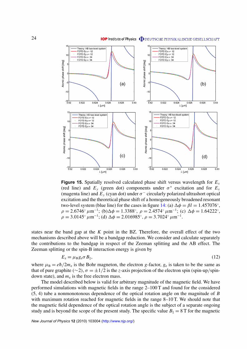
The phase shift difference 1φ = 1φR − 1φL introduced by the non-symmetric systemresponse under σ + (transition |1〉 → |2〉) and σ− (transition |3〉 → |4〉) circularly polarizedpulse excitation represents a measure for the rotation angle. The result of the polarization isto change the phase delay per unit length from βR(L) to βR(L) + 1βR(L). The atomic phase shift(βR(L),x(y)l) for the four cases described above is plotted in figure 15 and the rotation angleand the specific rotatory power per unit length, ρ = π(nL − nR)/λ0, where nL and nR are therefractive indices for left- and right-circularly polarized light, respectively, are given for eachcase. The specific rotatory power varies in the interval ρ = 2.46–3.7◦ µm−1, giving an averagevalue of ∼2962.24◦ mm−1. The corresponding anisotropy of the refractive indices for left- andright-circularly polarized light is of the order of 1n = nL − nR = 0.0103. The calculated naturalpolarization rotatory power, for the special case of a (5, 4) nanotube considered, exceeds thegiant gyrotropy reported in the artificial photonic metamaterials of up to 2500◦ mm−1 [25].We should note, however, that the complexity of the CNT molecular structure allows forengineering the optical activity in a wide range. By comparison, the optical activity of e.g. quartzilluminated by the D line of sodium light (λ = 589.3 nm), is 21.7◦ mm−1, implying refractiveindices difference |nL − nR| ∼7.1 × 10⁻⁵; ρ = 32.5◦ mm−1 for cinnabar (HgS). A comparison
New Journal of Physics 12 (2010) 103004 (http://www.njp.org/)

21
(a) (b)
(d)(c)
Figure 12. Expanded view of figure 11 showing the time evolution of the electricfield vector components Ex and Ey and the populations of all four levels underlinearly polarized optical pulse excitation at four different locations along thenanotube axis ((a) z = 175 nm; (b) z = 300 nm; (c) z = 425 nm; (d) z = 550 nm)measured from the left boundary z = 0 in figure 6.
of the specific rotatory power for a group of crystals is given in [43] (table), showing a widerange of variation from 2.24◦ mm−1 for NaBrO3 to 522◦ mm−1 for AgGaS2.
Liquid substances exhibit much lower values of specific rotatory power, e.g. ρ =
−0.37◦ mm−1 for turpentine (T = 10◦, λ = 589.3 nm); ρ = 1.18◦ mm−1 for corn syrup, etc.Cholesteric liquid crystals and sculptured thin films exhibit large rotatory power in the visiblespectrum, ∼1000◦ mm−1 [44] and ∼6000◦ mm−1 [45], respectively.
5. Magneto-optical activity of a chiral SWCNT in an axial magnetic field
5.1. Theoretical model
We shall now focus on the theoretical description of the resonant coherent nonlinear opticalactivity when a static magnetic field B‖ is threading the nanotube (figure 16). The rotation ofthe polarization of a plane-polarized electromagnetic wave propagating in a substance undera static magnetic field along the direction of propagation is known as Faraday rotation. Inthe presence of an axial magnetic field, the electronic band structure of a single CNT, andthe electronic states near the bandgap edge in particular, significantly changes, owing to the
New Journal of Physics 12 (2010) 103004 (http://www.njp.org/)

22
(a) (b)
(d)(c)
(f)(e)
Figure 13. (a) Time evolution of the Ex (blue line) and Ey (red line) componentsat the output facet of the simulated domain (Ey is initially set to 0 to model thelinearly polarized pulse). (b) Expanded view of (a) clearly showing the build-upwith time of the electric field vector Ey component amplitude at the output facet.(c) Time trace of the Ex component at the input facet (z = 0) and at the outputfacet (z = L). (d) Time trace of the Ey component at the input (Ey = 0) andat the output (z = L) facet. (e) Fourier (transmission) spectra of the time tracesin (c). (f) Fourier spectrum of Ey(z = L) at the output facet.
combined action of two effects: the spin-B interaction resulting in Zeeman splitting of the energylevels [14, 16, 46] and the appearance of the AB phase in the wave function [15, 17, 32, 47, 48],resulting in an additional energy level shift. The two symmetric subbands at K (K ′) point ofthe BZ are degenerate at B‖ = 0. An applied magnetic field along the nanotube axis lifts thisdegeneracy and shifts the energy levels. As a result, the energy gap of one of the subbands(K ′) becomes larger, while the energy gap of the other subband (K ) becomes smaller [46].
New Journal of Physics 12 (2010) 103004 (http://www.njp.org/)

23
(a) (b)
(d)(c)
Figure 14. Spatially resolved calculated gain coefficient per micron versuswavelength for Ex(Ey) electric field vector component of a σ + (red line) and σ−
(green line) circularly polarized ultrashort optical excitation and the theoreticalgain coefficient of a homogeneously broadened resonant two-level system (blueline) for (a) a pair of points z1 and z2 within the CNT separated by onedielectric resonant wavelength. The offset of the first point z1 is 5 nm from thebeginning of the nanotube structure modeled as an absorption/gain medium:1A = 0.033785 µm−1. (b) A pair of points z3 and z4 within the CNT, onedielectric length apart; z3 is shifted to the right by 1 nm with respect to z1:1A = 0.060104 µm−1. (c) A pair of points z5 and z6 within the active medium,separated by one dielectric wavelength; z5 is shifted by 1 nm to the right of z3:1A = 0.107539 µm−1. (d) A pair of points z7 and z8 within the active medium,separated by one dielectric wavelength; z7 is shifted by 1 nm to the right of z5:1A = 0.1291 µm−1.
Furthermore, the possibility of a magnetic field-induced metal–insulator transition has been putforward [49]. It has been theoretically predicted that the effect of the AB flux on the energygap is to induce oscillations between zero and a fixed value with a period of the flux quantum80 = h/e [16, 32, 50], resulting in periodical oscillations of the magneto-optical absorptionspectra.
At a fixed value of the static magnetic field, however, the orbital AB effect leads to auniform shift in the energy levels. Without loss of generality, we shall consider the electronic
New Journal of Physics 12 (2010) 103004 (http://www.njp.org/)
24
(a) (b)
(d)(c)
Figure 15. Spatially resolved calculated phase shift versus wavelength for Ex
(red line) and Ey (green dot) components under σ + excitation and for Ex
(magenta line) and Ey (cyan dot) under σ− circularly polarized ultrashort opticalexcitation and the theoretical phase shift of a homogeneously broadened resonanttwo-level system (blue line) for the cases in figure 14: (a) 1φ = βl = 1.457076◦,ρ = 2.6746◦ µm−1; (b)1φ = 1.3388◦, ρ = 2.4574◦ µm−1; (c) 1φ = 1.64222◦,ρ = 3.0145◦ µm−1; (d) 1φ = 2.016985◦, ρ = 3.7024◦ µm−1.
states near the band gap at the K point in the BZ. Therefore, the overall effect of the twomechanisms described above will be a bandgap reduction. We consider and calculate separatelythe contributions to the bandgap in respect of the Zeeman splitting and the AB effect. TheZeeman splitting or the spin-B interaction energy is given by
Ez = µBgeσ B‖, (12)
where µB = eh/2me is the Bohr magneton, the electron g-factor, ge is taken to be the same asthat of pure graphite (∼2), σ = ±1/2 is the z-axis projection of the electron spin (spin-up/spin-down state), and me is the free electron mass.
The model described below is valid for arbitrary magnitude of the magnetic field. We haveperformed simulations with magnetic fields in the range 2–100 T and found for the considered(5, 4) tube a nonmonotonous dependence of the optical rotation angle on the magnitude of Bwith maximum rotation reached for magnetic fields in the range 8–10 T. We should note thatthe magnetic field dependence of the optical rotation angle is the subject of a separate ongoingstudy and is beyond the scope of the present study. The specific value B‖ = 8 T for the magnetic
New Journal of Physics 12 (2010) 103004 (http://www.njp.org/)

25
Figure 16. Scheme of a single chiral nanotube (20, 10) threaded by an axialmagnetic field.
field selected is to demonstrate the maximum angle of Faraday rotation and, at the same time,was the maximum magnetic field of the static magnet available in the laboratory (in view ofcomparison with experiments at a later stage).
For a magnetic field B‖ = 8 T, the above equation gives an energy shift of Ez ≈ 0.46 meV,which corresponds to a resonant frequency ωz = 7.026 × 10¹¹ rad s−1.
The predicted oscillatory magnetic field dependence of the energy gap of a semiconductingnanotube [14, 51] is of the form
EG (8) =
3EG (0)
∣∣∣ 13 −
8
80
∣∣∣ , 068/80 6 1/2,
3EG (0)
∣∣∣ 23 −
8
80
∣∣∣ , 1/268/80 6 1,(13)
where EG(0) = hω0 is the energy gap at zero magnetic field (B = 0) and ω0 is the resonanttransition frequency.
For the case of a magnetic field B = 8 T with a flux 8 threading the (5, 4) nanotube cross-section with a diameter d = 0.611 45 nm, the ratio 8/80 = 0.000 57, and therefore the first ofthe above equations holds. This leads to an energy-level shift, or bandgap renormalization dueto the orbital AB effect of EAB = 3.37 meV, corresponding to a resonant angular frequencyωAB = 5.12 × 10¹² rad s−1. In an external magnetic field, the energy levels near the bandgap offigure 5 split and the spin degeneracy is lifted (see figure 17). The energy-level system can besplit into two reduced systems of levels, each of which represents a mirror image of the other.However, the symmetry is broken by the allowed optical transitions in each case. For simplicity,the AB uniform shift (hωAB) is not shown in figure 17. Another reason for selecting the magneticfield B = 8 T is that at this value the energy-level shift due to both AB and Zeeman splittingresults in a substantial change in the pumping resonant frequency (ωpump = ω0 − ωAB − 2ωz)
New Journal of Physics 12 (2010) 103004 (http://www.njp.org/)

26
Figure 17. Zeeman splitting (hωz) of the energy levels near the bandgap of a (5,4) nanotube in an external axial magnetic field. The original set of levels (|1〉–|4〉)is labelled by the (quasi-angular) orbital momentum quantum number l = 0, 1;the resulting energy levels are labelled by the projection of the total angularmomentum J = l + s along the nanotube axis (z). Two reduced sets of levels,where energetically they are closest to the band edge, can be identified, namely|1′
〉–|4′〉 and |1′′
〉–|4′′〉 (note that levels |4′
〉 and |3′′〉 are common to the two
systems). The energy bandgap Eg is shaded; 1 is the energy separation betweenthe l = 0 and l = 1 states (assumed, for simplicity, equal for the valence andconduction band states). The original system of levels, the stimulated opticallypumped transitions by σ +(−) light and relaxation processes are plotted in red.The black solid (dashed) arrows denote the resonant excitation of |1′
〉 → |2′〉
(|3′′〉 → |4′′
〉) transition by σ−(σ +) light. Note that the initial population (smallblack circles) is equally distributed between levels |1′
〉 and |3′〉 in the valence
band for the first (′) reduced system of levels, whereas the total population isresiding in level |3′′
〉 in the valence band of the second (′′) reduced systemof levels. The spontaneous emission rates, designated by wavy lines, and therelaxation rates are modified in a magnetic field, which is reflected by thesuperscript B. The small black arrows denote the spin-up and spin-down states;note that the spin-up state is energetically higher than the spin-down state in theconduction band, whereas the opposite is valid for the valence band states. Theforbidden transitions by the dipole optical selection rules are designated by ⊗.
with respect to the zero field case and therefore results in a considerable (tenfold, as will beshown below) enhancement of the optical rotation angle.
Analogously to the B = 0 case, the system Hamiltonian for an AL-handed SWCNT in anaxial magnetic field B 6= 0 (for the (primed-system), excited by a σ− pulse can be written in
New Journal of Physics 12 (2010) 103004 (http://www.njp.org/)

27
the form
H ′= h
ωz −
12
(�x − i�y
)0 0
−12
(�x + i�y
)ω0 − ωz 0 0
0 0 1 − ωz 0
0 0 0 1 + ωz
, (14)
where we have made the band gap renormalization with the AB shift, ω0 → ω0 − ωAB, giving atorque vector
γ =
(−�x , 0, 0, 0, 0, 0, − −�y, 0, 0, 0, 0, 0, ω0 − 2 ωz,
2 1 − ω0 − 2 ωz√
3,
2 1 − ω0 + 4 ωz√
6
).
(15)The time evolution of the four-level quantum system under an external time-dependent
dipole coupling perturbation is given by equation (2). Similar to section 3, 0i matrices areintroduced, according to
01 =
0 0 0 0
0 01 0 0
0 0 0 0
0 0 0 γ
, 02 =
0 0 0 0
0 − (01 + 02 + 03) 0 0
0 0 0 0
0 0 0 0
,
03 =
0 0 0 0
0 03 0 0
0 0 0 0
0 0 0 0
, 04 =
0 0 0 0
0 02 0 0
0 0 0 0
0 0 0 −γ
,
(16)
resulting in the following expressions for the diagonal components of the matrix σ , expressedin terms of the real state vector components,
σ11 =1
12
(3γ +
√6S15 (3γ − 01) +
(3 + 6S13 − 2
√3S14
)01
),
σ22 = −1
12
(3 + 6S13 − 2
√3S14 −
√6S15
)(01 + 02 + 03) ,
σ33 =1
12
(3 + 6S13 − 2
√3S14 −
√6S15
)03,
σ44 =1
12
(−3γ +
(3 + 6S13 − 2
√3S14
)02 −
√6S15 (3γ + 02)
).
(17)
The dephasing rate matrix 0t is a traceless matrix with all off-diagonal components equal to0µ, i.e. the transverse relaxation times T1 = T2 = · · · = T12 = 1/0µ. The longitudinal relaxationtimes appearing in the second of equation (2) are given by
T13 =4
201 + 02 + 03, T14 =
12
02 + 303, T15 =
6
3γ + 02. (18)
The macroscopic medium polarization vector components for this case are given by
Px = −℘NaS1,
Py = −℘NaS7
(19)
New Journal of Physics 12 (2010) 103004 (http://www.njp.org/)

28
and the resulting pseudospin equations are solved self-consistently with vector Maxwellequation (8) directly in the time domain. The second (′′) reduced-level system (figure 17) isdescribed by the following Hamiltonian,
H ′′= h
ω0 − ωz 0 0 0
0 ω0 + ωz 0 0
0 0 1 + ωz −12
(�x + i�y
)0 0 −
12
(�x − i�y
)1 + ω0 − ωz
, (20)
resulting in the torque vector of the form
γ =
(0, 0, 0, 0, 0, −�x , 0, 0, 0, 0, 0, �y, 2 ωz,
2 (1 − ω0 + ωz)√
3,
2 1 + ω0 − 4 ωz√
6
). (21)
The corresponding diagonal longitudinal relaxation rates matrix σ is given by
σ11 =1
12
(3γ +
(−3 + 6S13 + 2
√3S14
)02 +
√6S15 (3γ + 02)
),
σ22 = −1
12
(3 + 6S13 − 2
√3S14 −
√6S15
)03,
σ33 =1
12
(301 +
√6S15 (301 − 02) +
(3 − 6S13 − 2
√3S14
)02
),
σ44 = −14
(1 +
√6S15
)(γ + 01)
(22)
obtained with the introduction of the following 0i matrices,
01 =
−02 0 0 0
0 0 0 0
0 0 0 0
0 0 0 γ
, 02 =
0 0 0 0
0 −03 0 0
0 0 0 0
0 0 0 0
,
03 =
02 0 0 0
0 03 0 0
0 0 0 0
0 0 0 01
, 04 =
0 0 0 0
0 0 0 0
0 0 0 0
0 0 0 −(γ + 01)
.
(23)
The transverse relaxation rate matrix is given by equation (6), giving T1 = T2 = T3 = T7 =
T8 = T9 = 1/0µ and T4 = T5 = T6 = T10 = T11 = T12 = 1/0µ−1. The following expressions forthe longitudinal relaxation rates are obtained,
T13 = T14 =4
02 + 03, T15 =
2
γ + 01. (24)
The macroscopic polarization vector components are given by
Px = −℘NaS6,
Py = −℘NaS12.(25)
5.2. Simulation results for Faraday rotation
The simulated structure is the same as the one described in figure 6. We resonantly excite|1′
〉 → |2′〉 (|3′′
〉 → |4′′〉) transition by left (σ−) (right (σ +)) circularly polarized π -pulse with
New Journal of Physics 12 (2010) 103004 (http://www.njp.org/)

29
(a) (b)
(d)(c)
Figure 18. Spatially resolved calculated gain coefficient per micron versuswavelength for Ex(Ey) electric field vector component of a σ + (red line)and σ− (green line) circularly polarized ultrashort optical excitation and thetheoretical gain coefficient of a homogeneously broadened resonant two-levelsystem (blue line) at B = 8 T for a pair of points (zi , z j) separated by onedielectric resonant wavelength within the carbon nanotube, shifted from the leftboundary of the structure by offsets specified in figure 14. (a) Circular dichroism1A = 0.8048 µm−1; (b) 1A = 0.75392 µm−1; (c) 1A = 0.6661 µm−1 and(d) 1A = 0.598 µm−1.
pulse duration τ = 60 fs. The pulse central frequency is tuned in resonance with the transitionfrequency, ω0 − ωAB − 2ωz, and the pulse envelope is a Gaussian function. Owing to thecombined effect of the AB and Zeeman energy levels shift, the dipole matrix element ismodified. An estimate of the optical dipole matrix element in an axial magnetic field canbe obtained from the theory developed in [41], taking into account the bandgap reductionat B = 8 T, giving ℘ = 3.6205 × 10⁻²⁹ Cm. Note that this value is slightly different from thezero magnetic field value (see appendix B). We recalculate the relaxation times using theabove magnetic field dipole coupling constant, thus obtaining the following relaxation rates:01 = 2.914 ns−1, 02 = 9.79 ns−1, 03 = 9.77 ns−1. The intraband relaxation rate γ = 130 fs−1
and the dephasing rates 0µ = 800 fs−1 and 0µ−1 = 1.6 ps−1 are taken to be the same as forthe zero field case. Note that the initial boundary conditions are different for the excitationby σ− and σ + pulses. Whereas in the former case the initial population is assumed equallydistributed between the valence band levels (ρ1′1′i = ρ3′3′i = 1/2), closest to the band edge, in
New Journal of Physics 12 (2010) 103004 (http://www.njp.org/)

30
(a) (b)
(d)(c)
Figure 19. Spatially resolved calculated phase shift versus wavelength at B =
8 T for Ex (red line) and Ey (green dot) components under σ + excitation andfor Ex (magenta line) and Ey (cyan dot) under σ− circularly polarized ultrashortoptical excitation and the theoretical phase shift of a homogeneously broadenedresonant two-level system (blue line) for the cases in figure 18: (a) 1φ = βl =
22.011◦, ρ = −40.4033◦ µm−1; (b) 1φ = 21.378◦, ρ = −39.2413◦ µm−1; (c)1φ = 16.447◦, ρ = −30.19◦ µm−1; (d) 1φ = 11.161◦, ρ = −20.4871◦ µm−1.
the latter case the whole population is in the single valence band state (ρ4′4′i = 1). Similar tosection 4, the time evolution of the electric field vector components and the population of allfour levels is sampled at four points along the nanotube, and the real and imaginary parts ofthe complex propagation factor, giving the phase shift, and the absorption/gain coefficient arecalculated. The absorption/gain coefficients for resonant excitation by σ−(σ +) pulse are plottedon the same graph (figure 18) and the theoretical gain coefficient of a homogeneously broadenedtwo-level system is plotted for reference. Note that the resonance is shifted towards longerwavelengths due to the bandgap reduction. We should point out that the MCD spectra at B = 8 Tshown in figure 18 are quite distinct from the zero-magnetic field spectra (figure 14) for thenatural optical activity. While the σ− polarized pulse is amplified during the pulse propagationacross the nanotube, the σ + polarized pulse is absorbed, resulting in a much larger net circulardichroism. The average value of the MCD is 0.706 µm−1, an order of magnitude larger thanthe natural circular dichroism (cf section 4). The different behaviour of the calculated gain andabsorption spectra under σ−(σ +) polarized optical pulse excitation is a direct consequence of the
New Journal of Physics 12 (2010) 103004 (http://www.njp.org/)

31
discrete energy-level configuration describing the two cases. While the energy-level system fora σ− excitation is a four-level system, the one corresponding to a σ + excitation is a three-level3-system, due to level |2′′
〉 being completely decoupled from the rest of the levels, owing tothe dipole optical selection rules forbidding transitions from level |4′′
〉 → |2′′〉. The calculated
spectra in the latter case are reminiscent of electromagnetically induced transparency (EIT) andcoherent population trapping effects in a three-level system [52, 53]. In fact, the absorptionat resonance is close to zero and the shape of the spectrum is similar to the absorption dip,observed in EIT. The predicted destructive interference in an external axial magnetic field afterthe passage of the ultrashort pulse is a direct consequence of the specific time scales of theprocesses involved in the relaxation dynamics. This behaviour is confirmed by figure 19, wherethe induced phase shift is plotted as a function of wavelength. Whereas the phase shift spectrumfor a σ− pulse excitation is of the type of a two-level atomic phase shift, the shape of the phaseshift curve is double peaked, which is characteristic of the real part of the susceptibility in athree-level system, exhibiting EIT. The calculated average specific rotatory power in a magneticfield (B = 8 T) is −32.5804◦ µm−1, corresponding to an average refractive index anisotropy of6.497; the meaning of the minus sign is left rotation (counterclockwise when looking against thelight source). The predicted Faraday rotation at B = 8 T is nearly an order of magnitude greaterthan the natural optical rotation. We should note that the calculated rotation is a combinedeffect from the chirality of the nanotube and the magnetic field-induced rotation and thus canbe considered as an estimate for the magneto-chiral effect in a single nanotube. Using thedeveloped model, an investigation of the magnetic field dependence of the optical rotation iscurrently under way and will be the subject of a forthcoming paper.
6. Conclusions
We have developed a theoretical formalism and dynamical model for the description of thenatural optical activity and Faraday rotation in an individual chiral SWCNT in the coherentnonlinear regime under resonant ultrashort polarized pulse excitation. The model is based on adiscrete-level representation of the optically active states near the band edge, whereby chiralityis modelled by four-level systems, specific for each handedness, that are mirror reflections ofeach other and therefore non-superimposable. Thus, chirality is incorporated at a microscopiclevel in the model. The dynamics of the resonant coherent interaction of a polarized ultrashortlaser pulse with the discrete multilevel system are treated semiclassically within the coherentvector Maxwell-pseudospin formalism. For illustration purposes, we consider the specific caseof a (5, 4) SWCNT, although the model is valid for an arbitrary chiral nanotube. Furthermore,we provide an estimate of the effective dielectric constant and the optical dipole matrix elementfor transitions excited by circularly polarized light in a single nanotube ((5, 4) in particular).The model yields the time evolution of the optical pulse during its propagation due to theresonant coherent interactions, at each point along the nanotube, and thus enables extracting thecircular dichroism and phase shift spectra. Giant natural gyrotropy for the special case of a (5, 4)nanotube considered (3000◦ µm−1 at B = 0), exceeding the one of birefringent crystals, liquidcrystals and artificial metamaterials and thin films, is numerically demonstrated. Our resultsconfirm the possibility to determine single nanotube handedness by time-resolved circulardichroism and magneto-optical rotatory dispersion spectroscopy. In view of the possibilityof manipulating the nanotube chirality, we anticipate a much wider range of variation of thespecific optical rotation. This is, however, the subject of an ongoing further study using the
New Journal of Physics 12 (2010) 103004 (http://www.njp.org/)

32
proposed model and is beyond the scope of this paper. We show that the circular dichroism andspecific rotatory power in an axial magnetic field for the same (5, 4) nanotube is enhanced by oneorder of magnitude at higher magnetic fields (B = 8 T). To the best of our knowledge, the waythe external axial magnetic field affects the natural optical activity and the so-called magneto-chiral effect in the high-intensity nonlinear regime has not been investigated. These modelstudies are currently under way. We should note that although the model is developed for aresonant excitation, an off-resonant excitation, introducing detuning, can easily be implemented.
Acknowledgments
We are indebted to G Bastard, R Ferreira, C Flytsanis and C Voisin for stimulating discussions.GS acknowledges support through a visiting fellowship from Laboratoire Pierre Aigrain, EcoleNormale Supérieure, Paris, France.
Appendix A. Effective dielectric constant of an isolated SWCNT
We emphasize that our approach is an ensemble one. We consider a four-level atomic mediumconsisting of an ensemble of a large number (N � 1) of identical aligned CNTs with densityNa = 6.8 × 1024 m−3, each replica having a dielectric constant calculated as described below.In order to obtain a single nanotube’s dielectric properties, an averaging procedure overthe ensemble is performed to give on average a single nanotube within the microscopicsimulation domain volume. This assumption is generally valid for ergodic systems (for adetailed description of the method, see [38]).
In order to obtain an estimate of the dielectric constant of a single CNT, we use twoindependent approaches. Following the approach described in [54] based on the effectivemedium approximation, the local dielectric tensor of a cylindrical CNT can be written incylindrical coordinates as
ε(r , ϕ, z
)= ε‖r r + ε⊥
(z z + ϕ ϕ
), (A.1)
where ε‖ (ε⊥) are the principal components of the dielectric tensor of graphite parallel(perpendicular) to the normal axis of the graphite planes. The dielectric polarizability of a singleCNT in an external potential of the form Vm(r, 8) = V (r)eim8, i.e. no field applied parallel to thetube z-axis, which corresponds to the considered case of a circularly polarized electromagneticwave in a plane, perpendicular to the tube axis; an expression for the polarizability per unitlength is given in [55] in terms of the inner, r , and outer, R, radii of the nanotube, described asa hollow cylinder. In the quasistatic approximation m = 1 and the nanotube’s polarizability isanisotropic, given by
α1 = 4πε0εe R2
(ε‖λ − εi
) (ε‖λ + εe
)ρ2λ
−(ε‖λ − εe
) (ε‖λ + εi
)(ε‖λ − εi
) (ε‖λ − εe
)ρ2λ −
(ε‖λ + εe
) (ε‖λ + εi
) , (A.2)
where ρ = r/R, λ = (ε⊥/ε‖)1/2 and εi and εe are the dielectric constants of the internal and
external materials; for a free standing nanotube, we shall assume εi = εe = 1.An equivalent isotropic dielectric function, ε, of a solid cylinder with the nanotube’s
external radius, R, is introduced, according to
α′
1 = 4πε0εe R2 ε − εe
ε + εe. (A.3)
New Journal of Physics 12 (2010) 103004 (http://www.njp.org/)

33
The principal axes of the dielectric function tensor, ε‖ and ε⊥, in equation (A.2) canbe calculated from graphite ordinary and extraordinary ray refractive indices, no = 2.64 andne = 2.03, respectively [56]. Taking the inner radius d = 0.61145 nm of the (5, 4) nanotubeunder consideration and a typical value for the external nanotube radius of R ∼5 nm [57], andequalizing equation (A.2) and (A.3), one can obtain the equivalent isotropic dielectric constantof the anisotropic nanotube, ε = 5.33, giving a value n ≈ 2.3 for the refractive index.
We have compared the dielectric response function of a single (5, 4) CNT, calculated byTB models with different levels of complexity from [59, 60], with the value estimated from theabove effective medium approximation. Taking into account that the TB method, in general,underestimates the experimental data by 0.3 eV, the axial component of the imaginary part ofthe dielectric function tensor ε2zz at the transition energy Eµ,µ±1 = 1.982 eV gives a value inthe range n = 1.835–2.82 for the refractive index along the nanotube axis. Since our modelis in 1D, the transverse (xx) component (which is n ∼1) can be ignored. We are interestedin the axial component of the dielectric function tensor, yielding the refractive index profilealong the nanotube length, which is in good agreement with the value n = 2.3 obtained usingthe effective dielectric constant. We should note that a similar effective medium approach fordescription of the dielectric permittivity of a single nanotube within the FDTD computationalmethod has been successfully applied in modeling the thermal radiative properties of verticalarrays of multi-walled CNTs [61].
Appendix B. Matrix element for dipole optical transitions excited by circularly polarizedlight in a single SWCNT
For the calculation of the optical dipole matrix element under resonant circularly polarizedpulse excitation, we assume injecting a resonant ultrashort circularly-polarized pulse with pulseduration τ = 60 fs and excitation fluence S = 20 mJ m−2, in agreement with the experimentconducted in [37, 58].
In order to get an estimate of the dipole matrix element, we employ an extension ofthe effective mass method applied to chirality effects in CNTs proposed in [41]. It has beenshown that chirality effects can be described by an effective Hamiltonian, in which the couplingbetween the electron wavevector kz along the tube axis and the quasiangular momentum aroundthe tube circumference is taken into account. Using this Hamiltonian, a general expression forthe electron–photon matrix element between the initial state i and the final state f has beenderived ([41], equation (18)) depending on the incident pulse light intensity I .
In order to obtain a value for I , we calculate first the electric field amplitude correspondingto a power of S/τ , using the expression for the intensity of a plane wave P in W m−2 in adielectric [40],
E =
√2P
cnrefrε0, (B.1)
where nrefr is the medium refractive index. The volume energy density of an electromagneticwave in J m−3 in the expression for the matrix element is then given by
I =12ε0n2
refr E2. (B.2)
We substitute the chiral indices n = 5, m = 4 and all parameters (the resonant energyfor the transition induced by circularly polarized light, tube diameter, refractive index (see
New Journal of Physics 12 (2010) 103004 (http://www.njp.org/)

34
appendix A)) in equation (18) of [41]. Since we are considering resonant excitations, the kz valueshould be taken at the point in the BZ where the band gap occurs, i.e. the value of kz = 0.126 m−1
at the bandgap, when the zone-folding method is applied. Note that kz varies within theboundaries of the first BZ, namely −π/T 6 kz < π/T , where T = 3.3272 nm is the lengthof the unit cell. The maximum wavevector at the boundary of the BZ, kzmax = 9.44 × 10⁸ m−1.Substituting the value of the wavevector kz at the bandgap into equation (18) yields a dipolematrix element ℘ ∼1 × 10⁻³¹ Cm, which varies to 1 × 10⁻²⁹ Cm at the BZ boundary.
On the other hand, the relaxation time of a typical molecular transition in a single CNT hasbeen measured in the range of tens of ns (τsp = 7–110 ns) [58], which for the calculated (usingthe same TB method of Pz-orbitals) energy gap of the circularly polarized µ → µ + 1 transition,namely 1.982 eV, implies a value of 3 × 10⁻²⁹ Cm, which is in very good agreement with thevalue calculated using [41].
We have used the analytical expression for the dipole matrix elements of the interbandoptical transitions for arbitrary light polarization and nanotube chirality, recently givenin [62, 63], to obtain an independent estimate for the dipole moment matrix element. For thespecific case of a (5, 4) nanotube, the optical dipole matrix element is ℘ = 1.86 × 10⁻³⁰ Cm,which is in good agreement with the estimates previously obtained. We should note that the TBzone-folding approach of Goupalov et al does not take into account the curvature effects.
We assume the value 3 × 10⁻²⁹ Cm, since it is based on experimental results andis calculated by the expression for the spontaneous decay rate derived within theWeisskopf–Wigner approach, valid for both linearly and circularly polarized transitions. Asit turns out, the correct prefactor of the dipole matrix element is not significant since it is withinthe numerical error of the method.
References
[1] Born M 1915 Phys. Zeits. 16 251Oseen C W 1915 Ann. d. Physik. 48 1
[2] Kuhn W 1929 Zeits. f. Physik. Chemie. 4 14[3] Kirkwood J G 1937 J. Chem. Phys. 5 479[4] Drude P 1959 The Theory of Optics (New York: Dover)[5] Condon E U, Altar W and Eyring H 1937 J. Chem. Phys. 5 753[6] Condon E U 1937 Rev. Mod. Phys. 9 432[7] Rosenfeld L 1928 Zeits. f. Physik. 52 161[8] Desorby G E and Kabir P K 1973 Am. J. Phys. 41 1350[9] Dufey F 2006 Chem. Phys. 330 326
[10] Rikken G L A and Raupach E 1997 Nature 390 493[11] Atkins P W and Woolley R G 1970 Proc. R. Soc. 314 251[12] Sfeir M Y et al 2006 Science 312 554[13] Bachilo S M, Strano M S, Kittrell C, Hauge R H, Smalley R E and Weisman R B 2002 Science 298 2361[14] Jiang J, Dong J and Xing D Y 2000 Phys. Rev. B 62 13209[15] Ajiki H 2002 Phys. Rev. B 65 233409[16] Shyu F L, Chang C P, Chen R B, Chiu C W and Lin M F 2003 Phys. Rev. B 67 045405[17] Mortimer I B, Li L-J, Taylor R A, Rikken G L J A, Portugall O and Nicholas R J 2007 Phys. Rev. B 76 085404[18] Awschalom D D, Loss D and Samarth N (ed) 2002 Semiconductor Spintronics and Quantum Computation
(Heidelberg: Springer)[19] Fitts D D and Kirkwood J G 1955 J. Am. Chem. Soc. 77 4940
New Journal of Physics 12 (2010) 103004 (http://www.njp.org/)

35
[20] Verbiest T, Van Elshocht S, Kauranen M, Hellemans L, Snauwaert J, Nuckolls C, Katz T J and Persoons A1998 Science 282 913
[21] Sánchez-Castillo A, Román-Velázquez C E and Noguez C 2006 Phys. Rev. B 73 045401[22] Van Elshocht S, Verbiest T, Busson B, Kauranen M, Snauwaert J, Hellemans L, Persoons A, Nuckolls C,
Phillips K E and Katz T J 2000 Synth. Met. 115 201[23] Champagne B, André J-M, Botek E, Licandro E, Maiorana S, Bossi A, Clays K and Persoons A 2004
ChemPhysChem 5 1438[24] Jin W, Fukushima T, Niki M, Kosaka A, Ishii N and Aida T 2005 Proc. Natl Acad. Sci. USA 102 10801[25] Plum E, Fedorov V A, Schwanecke A S, Zheludev N I and Chen Y 2007 Appl. Phys. Lett. 90 223113[26] Tasaki S, Maekawa K and Yamabe T 1998 Phys. Rev. B 57 9301[27] Zarifi A and Pedersen T G 2008 Phys. Rev. B 77 085409[28] Romanov D A and Kibis O V 1993 Phys. Lett. A 178 335[29] Yevtushenko O M, Slepyan G Ya, Maksimenko S A, Lakhtakia A and Romanov D 1997 Phys. Rev. Lett.
79 1102[30] Slepyan G Ya, Maksimenko S A, Lakhtakia A, Yevtushenko O M and Gusakov A V 1998 Phys. Rev.
B 57 9485[31] Slepyan G Ya, Maksimenko S A, Lakhtakia A, Yevtushenko O and Gusakov A V 1999 Phys. Rev. B 60 17136[32] Ajiki H and Ando T 1993 J. Phys. Soc. Japan 62 1255[33] Gommans H H, Alldredge J W, Tashiro H, Park J, Magnuson J and Rinzler A G 2000 J. Appl. Phys. 88 2509[34] Zhang Y, Chang A, Cao J, Wang Q, Kim W, Li Y, Morris N, Yenilmez E, Kong J and Dai H 2001 Appl. Phys.
Lett. 79 3155[35] Samsonidze Ge G, Grüneis A, Saito R, Jorio A, Souza Filho A G, Dresselhaus G and Dresselhaus M S 2004
Phys. Rev. B 69 205402[36] Yang L, Anantram M P, Han J and Lu J P 1999 Phys. Rev. B 60 13874[37] Lauret J-S, Voisin C, Cassabois G, Delalande C, Roussignol Ph, Jost O and Capes L 2003 Phys. Rev. Lett.
90 057404[38] Slavcheva G 2008 Phys. Rev. B 77 115347[39] Slavcheva G 2008 Quantum Dots: Research, Technology and Applications ed R Knoss (New York: Nova
Science Publishers) pp 373–94[40] Yariv A 1988 Quantum Electronics 3rd edn (New York: Wiley)[41] Ivchenko E L and Spivak B 2002 Phys. Rev. B 66 155404[42] Rogacheva A V, Fedotov V A, Schwanecke A S and Zheludev N I 2006 Phys. Rev. Lett. 97 177401[43] Jerphagnon J and Chemla D S 1976 J. Chem. Phys. 65 1522[44] de Gennes P G 1974 The Physics of Liquid Crystals (Oxford: Clarendon)[45] Hodgkinson I, Wu Q W, Knight B, Lakhtakia A and Robbie K 2000 Appl. Opt. 39 642[46] Minot E D, Yaish Y, Sazonova V and McEuen P L 2004 Nature 428 536[47] Saito R, Dresselhaus G and Dresselhaus M S 1994 Phys. Rev. B 50 14698[48] Zaric S, Ostojic G N, Kono J, Shaver J, Moore V C, Strano M S, Hauge R H, Smalley R E and Wei X 2004
Science 304 1129[49] Lu J P 1995 Phys. Rev. Lett. 74 1123[50] Roche S, Dresselhaus G, Dresselhaus M S and Saito R 2000 Phys. Rev. B 62 16092[51] Ajiki H and Ando T 1994 Physica B 201 349[52] Boller K J, Imamoglu A and Harris S E 1991 Phys. Rev. Lett. 66 2593[53] Fleischhauer M, Imamoglu A and Marangos J P 2005 Rev. Mod. Phys. 77 633[54] Lü W, Dong J and Li Z-Y 2000 Phys. Rev. B 63 033401[55] Henrard L and Lambin Ph 1996 J. Phys. B: At. Mol. Opt. Phys. 29 5127, 5129 equation (4)[56] Palik E (ed) 1991 Handbook of Optical Constants of Solids II (Boston: Academic)[57] Garcia-Vidal F J, Pitarke J M and Pendry J B 1997 Phys. Rev. Lett. 78 4289[58] Wang F, Dukovic G, Brus L E and Heinz T F 2004 Phys. Rev. Lett. 92 177401
New Journal of Physics 12 (2010) 103004 (http://www.njp.org/)

36
[59] Popov V N and Henrard L 2004 Phys. Rev. B 70 115407[60] Popov V N 2004 New J. Phys. 6 17[61] Bao H, Ruan X and Fisher T S 2010 Opt. Express 18 6347[62] Goupalov S V 2005 Phys. Rev. B 72 195403[63] Goupalov S V, Zarifi A and Pedersen T G 2010 Phys. Rev. B 81 153402[64] Dumitrica T, Garcia M, Jeschke H O and Yakobson B I 2006 Phys. Rev. B 74 193406
New Journal of Physics 12 (2010) 103004 (http://www.njp.org/)