nonlinear analysis of spliced continuous rc girders ... analysis of spliced continuous rc girders...
TRANSCRIPT

Journal of Babylon University/Engineering Sciences/ No.(1)/ Vol.(24): 2016
71
Nonlinear Analysis of Spliced Continuous RC Girders Strengthened with (CFRP) Laminates using ANSYS
Abstract
This paper presents the details of the finite element analysis of spliced continuous reinforced concrete girders. Five spliced continuous girders and one non-spliced continuous girder were analyzed using the ANSYS program. Each spliced girder consisted of three precast segments spliced at two cast-in-place joints at the inflection points, using splices of hooked dowels. Three spliced girders were strengthened using different schemes of the carbon fiber reinforced polymer (CFRP) laminates. The concrete was modeled using (SOLID65) eight-node brick element and the steel reinforcement was modeled discretely using (LINK8) spar element. The straight parts of the spliced bars were modeled using discrete representation with interface elements using (COMBIN39) elements to represent the bond-slip behavior while the hooked part of each spliced bar was replaced by a single spring element. The CFRP laminates were modeled using (SHELL41) shell element. The interfaces between the precast concrete segments and the joints were modeled using CONTAC52 interface elements in conjunction with vertical spring elements to represent the dowel action of the steel bars that crossing the interfaces.
The ANSYS model succeeded to an acceptable degree in predicting the structural behavior of the analyzed spliced girders with average of differences of about 6% between the predicted and experimental ultimate load. Keywords: Finite Element, Spliced Girders, Reinforced Concrete, CFRP Laminates
لخالصةا تم تحليل . تقدم هذه الورقة تفاصيل التحليل بواسطة العناصر المحددة للروافد الخرسانية المسلحة الموصولة المستمرة االسناد
كل ). ANSYS(ولة مستمرة االسناد بواسطة برنامج ال خمسة روافد موصولة مستمرة االسناد باإلضافة الى رافدة واحدة غير موصرافدة موصولة تتكون من ثالث قطع مسبقة الصب يتم توصيلها مع بعضها عن طريق وصلتين يتم صبهما موقعيا في منطقتي نقطتي
فة من اشرطة الياف ثالثة روافد مصولة تمت تقويتها باستعمال تشكيالت مختل. انقالب العزوم من خالل تراكب االسياخ المعكوفةوتم تثميل اسياخ حديد ) SOLID65(تم تمثيل الخرسانة بواسطة عناصر طابوقية ذات ثمانية عقد ). CFRP(الكاربون البوليميرية
األجزاء المستقيمة من االسياخ المتراكبة تم تمثيلها عدديا بعقد منفصلة ترتبط بعقد الخرسانة ). LINK8(التسليح بواسطة عناصر وتدية اما بالنسبة للجزء المعكوف من كل . االنزالق-وذلك لتمثيل سلوك الترابط) COMBIN39(من نوع ) بينية(من خالل عناصر وسيطية
نوع فقد تم تمثيلها بواسطة عناصر قشرية) CFRP (ـاما اشرطة ال). Spring Element(سيخ فقد تم تمثيله بعنصر زنبركي )SHELL41 .( بين القطع الخرسانية المسبقة الصب والوصالت المصبوبة موقعيا قد تم تمثيلها باستعمال ان مفاصل التقاء االوجه
بالتزامن مع عناصر زنبركية عمودية لتمثيل مقاومة االسياخ الفوالذية المارة خالل ) CONTAC52(من نوع ) بينية(عناصر وسيطية .هذه المفاصل للحركة العمودية
ه الدراسة نحج الى درجة مقبولة في تنبأ السلوك االنشائي للجسور الموصولة التي تم تحليلها ان التحليل النظري المتبع في هذ .بين الحمل األقصى المتوقع والعملي%) 6(وبمعدل فروقات بحدود
الروافد الموصولة، خرسانة مسلحة، اشرطة الياف الكاربون البوليميرية العناصر المحددة،: الكلمات المفتاحية1. Introduction
Splicing of precast concrete segments is considered as a powerful technique to increase the span ranges for precast concrete girders and overcome limitations of fabrication, shipping, and erection of very long precast concrete girders. (Castrodale and
Ammar Yasir Ali University of Babylon/College of Engineering
Mohammed Mansour Kadhum University of Babylon/College of Engineering
Haider Ali Al-Tameemi University of Kufa/College of Engineering

Journal of Babylon University/Engineering Sciences/ No.(1)/ Vol.(24): 2016
72
White, 2004). A spliced girder is defined as a prefabricated reinforced concrete member that is made of two or more relatively long segments that are assembled together to produce a single girder (Castrodale and White, 2004).
The splicing of precast concrete segments is usually achieved by using cast-in-place reinforced concrete joints to connect the adjacent precast segments of the spliced girders. The reinforced concrete joints are used to transfer forces between the precast elements, so that these joints are subjected to shear, tension or flexure. The integrity of the reinforced concrete joints may be achieved by utilizing reinforcement lap splicing and/or post-tensioning (Junbao, 2004).
Information concerning the spliced girder construction is limited and the available design specifications do not clearly address the design of spliced girder. The design of spliced girders requires consideration of various issues which are typically not common for the designer of conventional precast concrete (Castrodale and White, 2004). Therefore, the use of finite element analysis to predict the stresses and deformations will give better understanding about the structural behavior of such girders and thereby optimize the design for structural efficiency and economy. 2. Details of Tested Girders
The girders tested by (Ali et. al., 2015) were analyzed using the finite element (ANSYS) model in the present study. Each girder was continuous over two spans, each span length was 900 mm and the total length of the girder was 2,000 mm. One girder was non-spliced as a control girder (CB) as shown in Fig. 1.Whereas the other five girders were spliced at the inflection points using splices of hooked dowels anchored into cast-in-place joints. Each spliced girder consisted of three precast segments and two cast-in-place joints in between. Two precast segments were at the boundaries, while the third precast segment was at the middle. The steel bars of the main reinforcement were extended out of; the interior end of each outer precast segment and both ends of the middle precast segment as 90° hooks. The joints represented the splice regions of the extended hooks that formed from the assemblage of the precast segments. For all the five spliced girders, the development length for the 90° hook of each joint was half the length required by ACI-Code 318-11. However, these girders differed in other details of the joints as follows: Girder (CB.5ld): without any strengthening at joint, as shown in Fig. 2. Girder (CB.5ldHS): strengthened with internal horizontal stirrups which extended out
from each precast segment into the joints, as shown in Fig. 3. Girder(CB.5ld-LCF): strengthened at the joints with longitudinal CFRP laminates as
two strips of total width of 68 mm bonded at each top and bottom faces, as shown in Fig. 4.
Girder (CB.5ld-HCF): strengthened at joints with horizontal CFRP laminates as two strips bonded at each lateral side of the joints. A full wrapped CFRP laminate was used at each end of the horizontal CFRP laminates, as shown in Fig. 5.
Girder (CB.5ld-2ICF): strengthened at joints with 450 inclined CFRP laminates as three strips bonded at each lateral side of the joints extended in the same inclined direction through the top and bottom faces, as shown in Fig. 6. The yield stresses were 707 MPa for the bars size φ 10 mm and 462 MPa for the bars size
φ6 mm.The cylinder compressive strengths of concrete were 33.39 MPa for precast segments and 35.3 MPa for joints. The thickness of the unidirectional CFRP fabric was 0.131 mm and the tensile strength and modulus of elasticity were 4300 MPa and 234 GPa respectively.

Journal of Babylon University/Engineering Sciences/ No.(1)/ Vol.(24): 2016
73
Fig. 2- Details of Girder CB.5ld
Fig. 3- Details of Girder CB.5ldHS
Fig. 4- Details of Girder CB.5ld-LCF
Fig. 1- Details of Girder CB

Journal of Babylon University/Engineering Sciences/ No.(1)/ Vol.(24): 2016
74
Fig. 5- Details of Girder CB.5ld-HCF
Fig. 6- Details of Girder CB.5ld-2ICF
3. Finite Element Analysis of Tested Girders
The structural behavior of the tested spliced and non-spliced girders was investigated numerically using finite element method. The computer program ANSYS (Version 11) was used to perform this numerical analysis. The nonlinearity that included in ANSYS model was mainly caused by stress transfer across the cracked concrete blocks, post-cracking tensile stiffness of the concrete, bond-slip of longitudinal reinforcement in the splice joints, and geometry discontinuity due to interfaces of the splice joints. 3.1. Modeling of Concrete
8-node brick element (SOLID65) was used to model the concrete. This element is capable of simulating the behavior of brittle material, cracking in tension and crushing in compression. In the ANSYS model, the Willam and Warnke model was used to compute the failure surface of the concrete (Willam and Warnke,1975). Smeared cracking model was used to represent the cracking of concrete. The concrete is assumed to behave as isotropic elastic material before crushing or cracking. When the concrete crushing, is assumed to have lost its stiffness in all directions. After the first cracking has occurred, it is assumed that the cracked concrete becomes orthotropic and its stiffness is reduced to a negligible value in the crack normal direction (Chen and Saleeb, 1982). Tow reduction factors to the uncracked shear modulus were introduced to account the ability of concrete to transfer shear forces across the crack interface. The two coefficients of shear strength reduction are βo for the case of opened crack and βc for the case of closed crack (ANSYS, 2007). In the present study, βowas assumed to be (0.15) and (0.21) for the concrete of precast segments and joints respectively, while βc was assumed to be (0.78) for both the precast segments and joints.

Journal of Babylon University/Engineering Sciences/ No.(1)/ Vol.(24): 2016
75
3.2. Modeling of Steel Reinforcement In the present study, except of the flexural reinforcing bars in the joints (bars with
hooks), all the reinforcing bars were represented by using 2-node discrete representation (LINK8). The straight parts of the flexural reinforcing bars in the joints were represented by using 2-node discrete representation (LINK8) with interface element (COMBIN39) as shown in Fig. 7 in order to simulate the bond-slip between steel bars and concrete. While the hook of each bar was idealized as a single spring (COMBIN39) connecting the straight part end to the concrete as illustrated in Fig. 8. The hook spring followed a constitutive model differs from that one used to bond-slip representation of straight bar.
The uniaxial stress-strain relation for steel was idealized as a bilinear curve, representing elastic-plastic behavior with strain hardening. This relation was assumed to be identical in tension and in compression. In the present study the modulus of elasticity (Es = 200000 GPa), and Poisson’s ratio (νs = 0.3) were used and the strain hardening modulus (ET) was assumed to be (0.01 Es).
3.2.1. Bond-Slip Modeling for Straight Bar in the Joints
The relationship between local bond stress (τ) and slip (s) at bar- concrete interface along the longitudinal direction, (x), was represented using the prediction model for the bond stress – slip relationship proposed in the Ceb-Fib Model Code90 (1999) (Desnerck and Taerwe, 2010) as shown in Fig. 9, which can be expressed as follows:
Fig.7- Discrete representation with interface element
Fig. 8- Modelling of Hook Anchorage (86)

Journal of Babylon University/Engineering Sciences/ No.(1)/ Vol.(24): 2016
76
for …..(1)
,
4.06.07.10.2 cfS
for 0.6 …..(2)
,
3.0 cf for …..(3)
Where τ is the bond stress (N/mm2), is the slip value (mm), and is compressive strength of concrete (N/mm2)
The relationship between the bond force and slip value for the straight bar embedded in the joint can be obtained from;
…..(4) Where F is bond force (N), d is diameter of bar (mm) and l is distance between two
adjacent springs (mm)
These equations used to define the force-displacement relationship of the
nonlinear spring elements (COMBIN39), which was established between the relative bar element node and concrete element node along the longitudinal (x) direction. While the other transverse degree of freedoms of these two nodes were coupled. 3.2.2. Modeling of Hook Anchorage The force-displacement relationship of the nonlinear spring elements (COMBIN39), which was established at the end of each straight part of the flexural bars in the joints to model the hook anchorage, was defined using the hook constitutive model proposed by Soroushian et al. ( Soroushian et al.,1988) , as shown in Fig. 10,which can be expressed as follows:
for …..(5) for 2.54 …..(6)
for …..(7)
Fig. 9- Prediction Model for the Bond Stress-Slip Relationship According to Ceb-Fib Model Code90 (Desnerck and Taerwe, 2010)

Journal of Babylon University/Engineering Sciences/ No.(1)/ Vol.(24): 2016
77
( in (kN) and in (mm) ) …..(8) Where p is hook pullout force (kN) and is displacement (mm) 3.3. Modeling of CFRP Laminates
Three dimensional shell element (SHELL41) was used to model CFRP sheets. The behavior CFRP laminates used in the present study was assumed to have linearly elastic stress-strain relationship up to failure and does not exhibit any plastic behavior before rupture. Perfect bond between was assumed between the concrete and CFRP laminates. 3.4. Modeling of Interfaces between Precast Segments and Joints
In this study, two combinations of interface models were used to idealize the interaction at the interfaces between precast segments and cast-in-place joints. The first interface model is capable of resisting only compressive force in the direction normal to the interface surfaces and Coulomb shear friction in the tangential direction. 3-D node-to-node contact element (CONTAC52) was used to idealize this interface model. In this study, the initial state of the interface was assumed to be closed but sliding.
The second model was used to idealize the dowel action of the bars crossing the interface surfaces. The nonlinear spring element (COMBIN39) with appropriate force-displacement relationship was used to represent this model. 3.4.1. Modeling of Dowel Action
The force-displacement relationship of the nonlinear spring elements (COMBIN39), which was established at the interface to model the dowel action of bars crossing the interface, is given by (Ollgaard et al., 1971):
558.0Usdud )
e11(FF …... (9)
Where ∆Us is tangential displacement (mm), Fd is dowel force and Fdu = ultimate dowel force, given by (Millard and Johnson, 1984):
Fdu = y'
c2 ff2.13.1 …... (10)
Where is bar diameter (mm) 3.5. Finite Element Meshing
By means of symmetry, only a half of each girder was modeled and analyzed.
Fig. 10- Hook Constitutive Model According to Soroushian et al. ( Soroushian et al.,1988)

Journal of Babylon University/Engineering Sciences/ No.(1)/ Vol.(24): 2016
78
Each tested girder has only one plane of symmetry in the x–y plane, which halving the girder longitudinally, as shown in Fig. 11.
In the finite element modeling, mesh density is considered as an effective parameter to obtain better results accuracy with economical computation time. In this study, an appropriate mesh density was selected, when any increase in the mesh density became ineffective on the results accuracy. The best convergence was obtained, when the number of elements for one-half of girder was equal (4820). Figs. 12 shows the convergence study which carried out for the control girder model. It was found that the increase in the number of elements to (7726) had a negligible effect on the deflection at mid span. Fig. 13 shows the mesh modeling for the control girder
Fig. 12- Mid Span Deflection verses Number of Elements of Girder CB
Fig. 11- Symmetry plane of Control Girder for Continuous Girders

Journal of Babylon University/Engineering Sciences/ No.(1)/ Vol.(24): 2016
79
X
Y
Z
F
3.6. Boundary Conditions and Loading Points
The boundary conditions and the loading points need to be applied at nodes where the loads and the supports exist in the experimental model. As well as, the nodes at the plane of symmetry need to be fixed in the direction normal to that plane (Uz=0).
The supports were represented by constrained the nodes of lower transverse centerline of steel plates, which located under each girder at supporting points. The nodes that represents a roller support were constrained in y-direction (Uy=0), while the nodes that represented a pin support were constrained in y-direction and in x-direction (Uy=0 and Ux=0).
The external load was applied at the transverse centerline of the steel plates, which located at loading points on the top face of each girder. The total applied was distributed between the centerline nodes according to the surrounding area of each node. The boundary condition and loading distribution are shown in Figs. 14 and 15.
Fig. 13- Mesh Modeling for Control Girder
Fig. 14- Boundary Conditions for Pin Support and Nodes of Symmetry plane
Fig. 15- Line load distribution and Boundary Conditions for Nodes of Symmetry plane
12.5P/300 20.5P/300
13P/300 17P/300
12P/300
Journal of Babylon University/Engineering Sciences/ No.(1)/ Vol.(24): 2016
80
4. Comparison between Numerical and Experimental Results This comparison is made in term of load-deflection curves, ultimate load and
deflection at service load. 4.1. Load- Deflection Curves
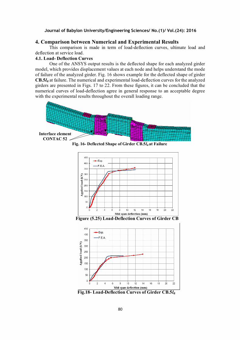
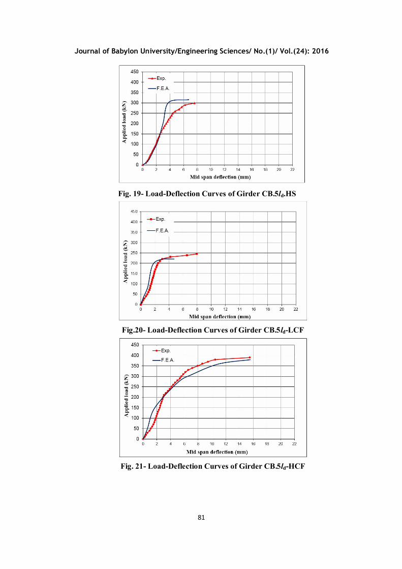
One of the ANSYS output results is the deflected shape for each analyzed girder model, which provides displacement values at each node and helps understand the mode of failure of the analyzed girder. Fig. 16 shows example for the deflected shape of girder CB.5ld at failure. The numerical and experimental load-deflection curves for the analyzed girders are presented in Figs. 17 to 22. From these figures, it can be concluded that the numerical curves of load-deflection agree in general response to an acceptable degree with the experimental results throughout the overall loading range.
Fig. 16- Deflected Shape of Girder CB.5ld at Failure
Figure (5.25) Load-Deflection Curves of Girder CB
Fig.18- Load-Deflection Curves of Girder CB.5ld
Interface element CONTAC 52
Journal of Babylon University/Engineering Sciences/ No.(1)/ Vol.(24): 2016
81
Fig. 19- Load-Deflection Curves of Girder CB.5ld.HS
Fig.20- Load-Deflection Curves of Girder CB.5ld-LCF
Fig. 21- Load-Deflection Curves of Girder CB.5ld-HCF

Journal of Babylon University/Engineering Sciences/ No.(1)/ Vol.(24): 2016
82
4.2. Ultimate Load
The comparison between the numerical ultimate loads and the experimental ultimate loads are described in Table 1. As shown in this table, the ultimate loads resulted from the finite element analysis gave an accepted agreement with the corresponding values of the experimental girders. The average of differences between the predicted and experimental ultimate loads was about 6%.
Ultimate load (kN) Girder Numerical (PuF.E.A.) Experimental (PuExp.)
CB 342.5 360 0.95
CB.5ld 217 230 0.94
CB.5ld.HS 316 300 1.05
CB.5ld-LCF 220 245 0.90
CB.5ld-HCF 380.6 390 0.98
CB.5ld-2ICF 312 337 0.93
Average of ( ) 0.96
4.3. Deflection at Service Load
Table 2 presents the comparison between the numerical and experimental mid span deflection values at the service load for each girder. The service load is consider as 0.65 of the ultimate load. This table shows that the deflection values resulted from the finite element analysis gave an accepted agreement with the corresponding values of the experimental girders. The average of differences between the predicted and experimental deflection values at service load was about 14%.
Fig.22- Load-Deflection Curves of Girder CB.5ld-2ICF
Table 1 Comparison between Numerical and Experimental Ultimate Loads

Journal of Babylon University/Engineering Sciences/ No.(1)/ Vol.(24): 2016
83
Mid span deflection at Service load (mm) Girder
Numerical (Δs F.E.A.) Experimental (Δs Exp.)
CB 3 3.6 0.83
CB.5ld 3.4 3.4 1.00
CB.5ld.HS 3 3.3 0.91
CB.5ld-LCF 1.4 1.9 0.74
CB.5ld-HCF 4.3 4.2 1.02 CB.5ld-2ICF 2 2.4 0.83
Average of ( ) 0.89
5. Conclusions Based on the comparison between the predicted results and the corresponding
experimental results, the following remark points can be concluded:- The numerical analysis using the computer program (ANSYS) in conjunction with the
adopted models succeeded to an acceptable degree in predicting the structural behavior of the analyzed spliced girders throughout the overall loading range.
The predicted ultimate loads gave a good agreement with the corresponding values of the test data. The average of differences between the predicted and experimental ultimate loads was about 6%.
The predicted deflection values at service load were found to be in an accepted agreement with the corresponding values of the test data. The average of differences between the predicted and experimental deflection values at service load was about 14%.
References Ali, Ammar, Y.; Kadhum, Mohammed, M.; and Al-Tameemi, Haider, A., 2015,
“Experimental Investigation for Behavior of Spliced Continuous RC Girders Strengthened with CFRP Laminates” Journal of Babylon University/Engineering Sciences, accepted for publish (Vol. (23), No. (3), 2015).
ANSYS, 2007, “ANSYS Help” Release 11.0, USA, Copyright 2007. Castrodale, R., and White, C., 2004, “Extending Span Ranges of Precast Prestressed
Concrete Girders” National Cooperative Highway Research Program (NCHRP) Report 517, Transportation Research Board, Washington, D.C.
Chen, W.F., and Saleeb, A.F., 1982, “Constitutive Equations for Engineering Materials” John Wiley and Sons, USA.
Desnerck, G.P., and Taerwe, L., 2010, “A Local Bond Stress-Slip Model for Reinforcing Bars in Self-Compacting Concrete” Korea Concrete Institute, Korea, Seoul.
Junbao, H., 2004, “Structural Behaviour of Precast Component Joints with Loop Connection” Ph.D. Thesis, National University of Singapore, Singapore.
Millard, S., and Johnson, R., 1984, “Shear Transfer across Cracks in Reinforced Concrete due to Aggregate Interlock and to Dowel Action” Magazine of Concrete
Table 2 Comparison between Numerical and Experimental Mid Span Deflection Values at Service Load

Journal of Babylon University/Engineering Sciences/ No.(1)/ Vol.(24): 2016
84
Research, Vol. (36), No. (126) March. Ollgaard, J.G.; Slutter, R.G.; and Fisher, J.W., 1971, “Shear Strength of Stud Connectors
in Lightweight and Normal Weight Concrete” AISC Engineering Journal, Vol. (8), No. (2), pp. 55-64.
Soroushian, P.; Obaseki, K.; Nagi, M.; and Rojas M., 1988, “Pullout behaviour of hooked bars in exterior beam-column connections” ACI Structural Journal, Vol.85, No.3, May-June, pp.269-276.
Willam, K., and Warnke, E., 1975, “Constitutive Model for the triaxial behavior of Concrete” Proceedings, International Association for Bridge and Structural Engineering, Vol. 19, ISMES, Bergamo, Italy.