non-destructive evaluation and accreditation of … · non-destructive evaluation and accreditation...
TRANSCRIPT
Non-destructive Evaluation and
Accreditation of Diagnostic Tests
on Concrete
SCCT Annual Concrete Seminar 2012
(18 April 2012)
Ir Dr Wallace W.L. LAI
Research Fellow, Department of Civil and Structural Engineering, HK PolyU
Visiting Scientist, Federal Institute of Materials Res. and Testing (BAM), Berlin, Germany
Dr Fiona W.Y. CHAN
Accreditation Officer, Hong Kong Accreditation Service,
Innovation and Technology Commission, The HKSAR Government
Ir Prof. C.S. POON
Professor, Department of Civil and Structural Engineering, HK PolyU
Contents 1. Introduction
2. Mandatory Building Inspection Scheme (MBIS) and local
specifications
3. Diagnosis of buildings and infrastructures by NDE?
4. NDE: from military/planetary/medical sciences to civil/building
engineering/surveying
5. NDE: from visual to internal inspection
6. The concept ‘NDE-structural health monitoring (NDE-SHM)’
7. Challenges of NDE
8. Accreditation of diagnostic tests on concrete in Hong Kong
9. Conclusion
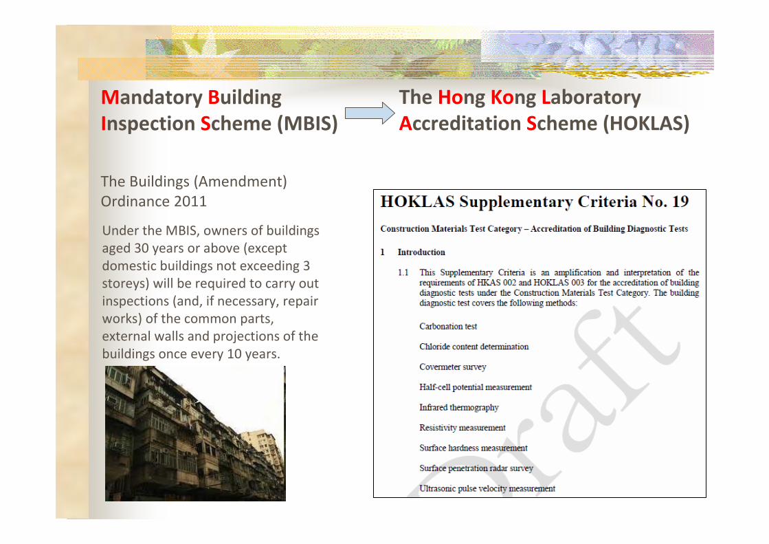
Mandatory Building The Hong Kong Laboratory
Inspection Scheme (MBIS) Accreditation Scheme (HOKLAS)
The Buildings (Amendment)
Ordinance 2011
Under the MBIS, owners of buildings
aged 30 years or above (except
domestic buildings not exceeding 3
storeys) will be required to carry out
inspections (and, if necessary, repair
works) of the common parts,
external walls and projections of the
buildings once every 10 years.
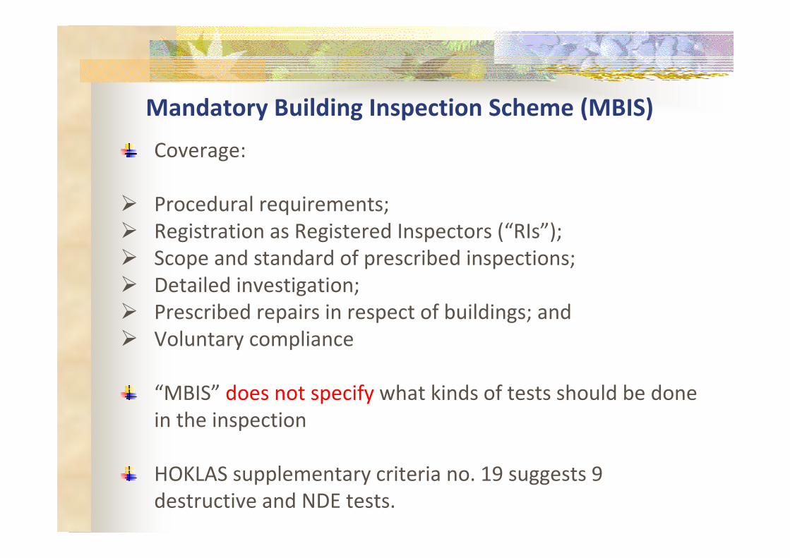
Mandatory Building Inspection Scheme (MBIS)
Coverage:
� Procedural requirements;
� Registration as Registered Inspectors (“RIs”);
� Scope and standard of prescribed inspections;
� Detailed investigation;
� Prescribed repairs in respect of buildings; and
� Voluntary compliance
“MBIS” does not specify what kinds of tests should be done
in the inspection
HOKLAS supplementary criteria no. 19 suggests 9
destructive and NDE tests.
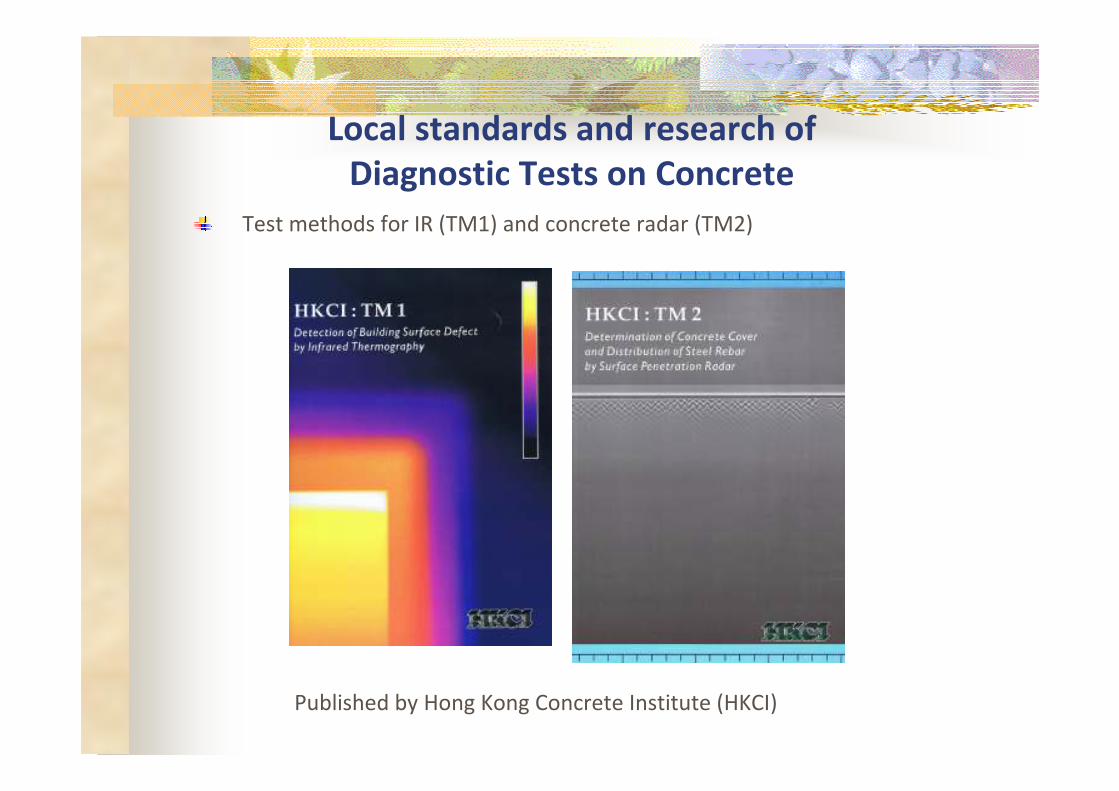
Local standards and research of
Diagnostic Tests on Concrete
Test methods for IR (TM1) and concrete radar (TM2)
Published by Hong Kong Concrete Institute (HKCI)
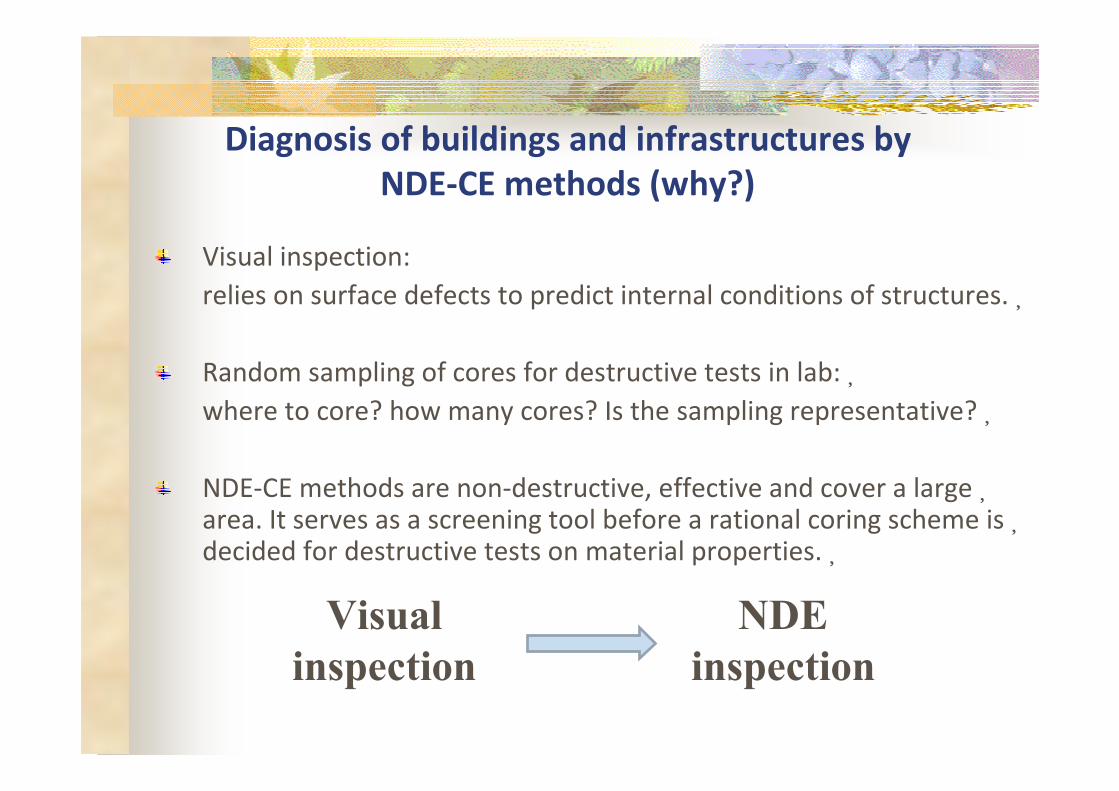
Diagnosis of buildings and infrastructures by
NDE-CE methods (why?)
Visual inspection:
relies on surface defects to predict internal conditions of structures.�
Random sampling of cores for destructive tests in lab:�where to core? how many cores? Is the sampling representative?�
NDE-CE methods are non-destructive, effective and cover a large�area. It serves as a screening tool before a rational coring scheme is�decided for destructive tests on material properties.�
Visual NDE inspection inspection
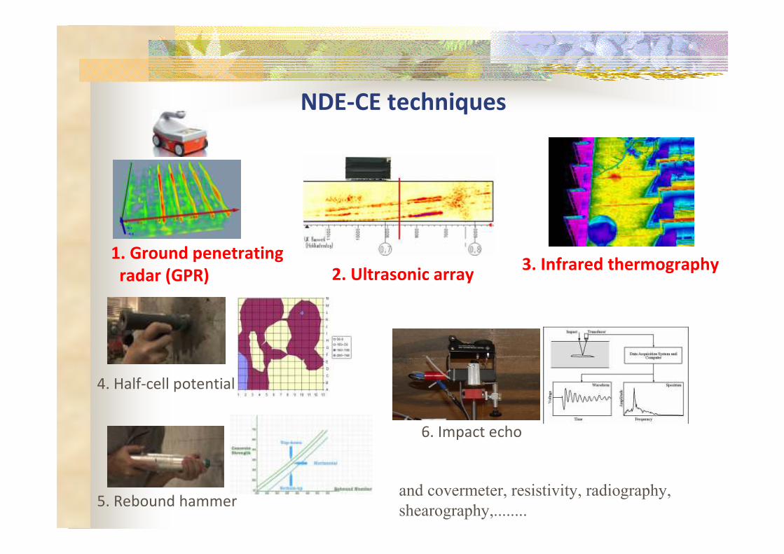
NDE-CE techniques
1. Ground penetrating
radar (GPR)
4. Half-cell potential
5. Rebound hammer
3. Infrared thermography 2. Ultrasonic array
6. Impact echo
and covermeter, resistivity, radiography, shearography,........
Criteria for NDE techniques for in-situ inspection
Measured parameters related to parameters of interest
(e.g. cover depth, center to center of steel bar, debond in
external wall, etc.)
High data resolutions (e.g. data in every 10mm)
Effective data acquisition
Provide detailed digital and traceable records

-
NDE: from military/planetary/ medical sciences
South Polar Layered Deposits on Mars
Gro
un
d
pe
ne
tra
tin
g
rad
ar
Ult
raso
nic
ph
ase
a
rra
y
Infr
are
d
the
rmo
gra
ph
y
Apollo 17 mission on the
Moon
Destroyer sounding
submarine Medical check for fetus
Missile guidance
civil/building
engineering/ surveying
Medical

From visual to NDE inspection
1. Ground penetrating radar (GPR)
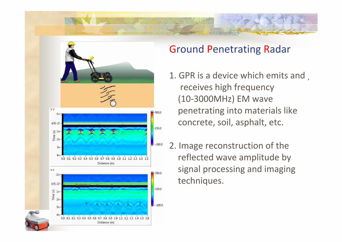
Ground Penetrating Radar
1. GPR is a device which emits and�receives high frequency
(10-3000MHz) EM wave
penetrating into materials like
concrete, soil, asphalt, etc.
2. Image reconstruction of the
reflected wave amplitude by
signal processing and imaging
techniques.
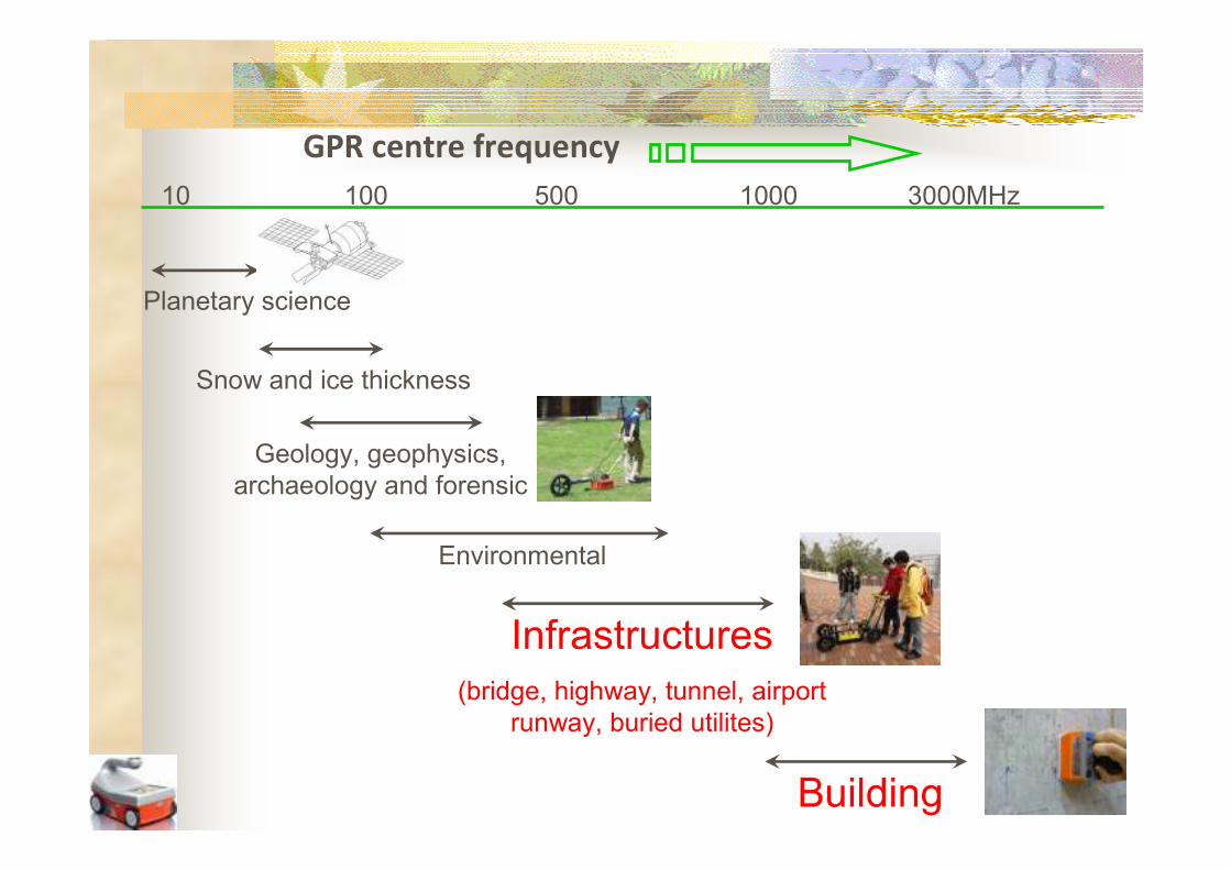
10 100 500 1000 3000MHz
GPR centre frequency
Planetary science
Snow and ice thickness
Geology, geophysics, archaeology and forensic
Environmental
Infrastructures (bridge, highway, tunnel, airport
runway, buried utilites)
Building
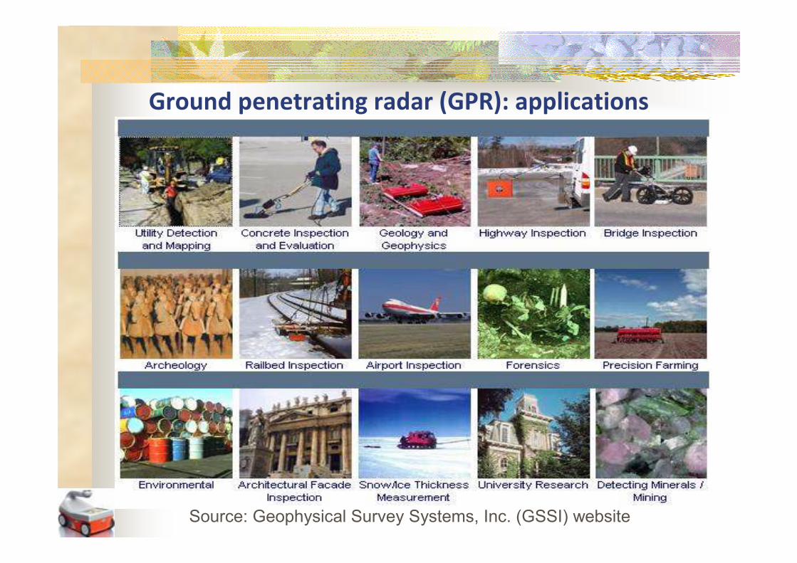
Ground penetrating radar (GPR): applications
Source: Geophysical Survey Systems, Inc. (GSSI) website
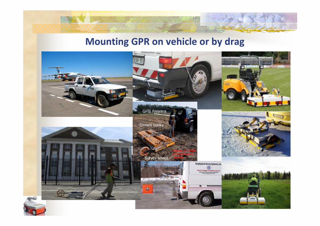
Mounting GPR on vehicle or by drag
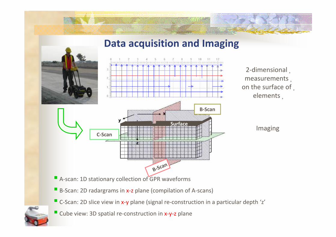
Data acquisition and Imaging
2-dimensional�measurements�
on the surface of�elements�
Surface
C-Scan
B-Scan
Imaging
B-Scan
� A-scan: 1D stationary collection of GPR waveforms
� B-Scan: 2D radargrams in x-z plane (compilation of A-scans)
� C-Scan: 2D slice view in x-y plane (signal re-construction in a particular depth ‘z’
� Cube view: 3D spatial re-construction in x-y-z plane
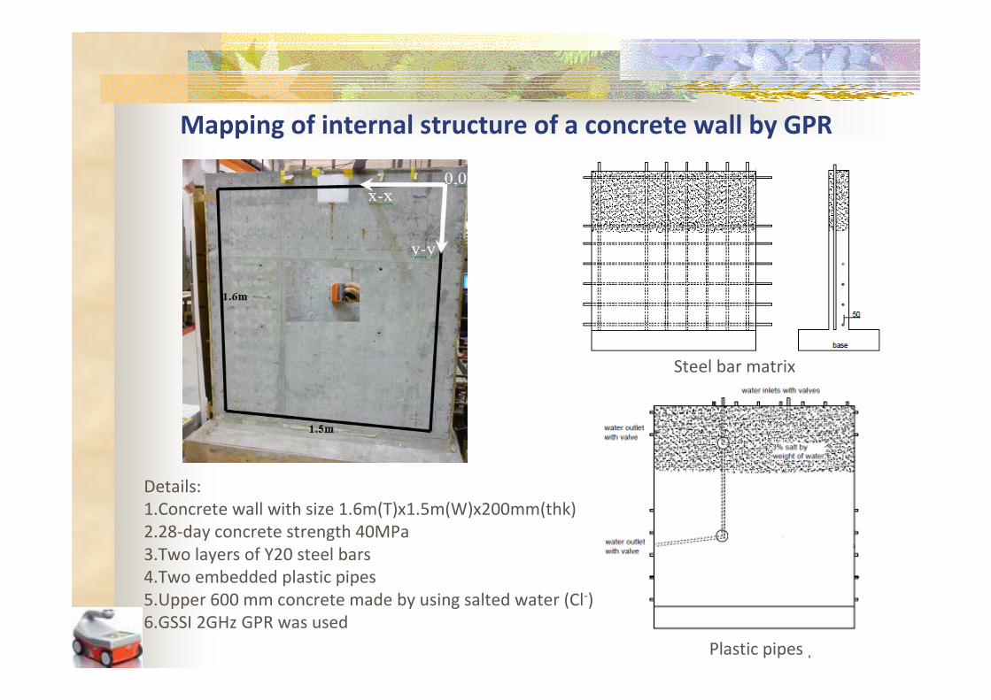
Mapping of internal structure of a concrete wall by GPR
Steel bar matrix
Details:
1.Concrete wall with size 1.6m(T)x1.5m(W)x200mm(thk)
2.28-day concrete strength 40MPa
3.Two layers of Y20 steel bars
4.Two embedded plastic pipes
5.Upper 600 mm concrete made by using salted water (Cl-)
6.GSSI 2GHz GPR was used
Plastic pipes�

Useful GPR parameters in B-scan radargram
(1)
(2)
(3) (4)
A B C D E
Information contained in GPR data:
1. Concrete cover depth
2. Thickness of concrete wall
3. Positions and spacing of embedded objects
(steel bars, plastic pipes)
4. Amplitude of the steel bar reflections
Surface CScan
BScan
B
Scan
x
z
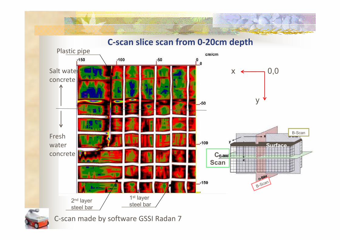
C-scan slice scan from 0-20cm depth
Surface
C
Scan
BScan
BScan
x
y
0,0
Plastic pipe
1st layer steel bar
2nd layer steel bar
C-scan made by software GSSI Radan 7
Salt water
concrete
Fresh
water
concrete
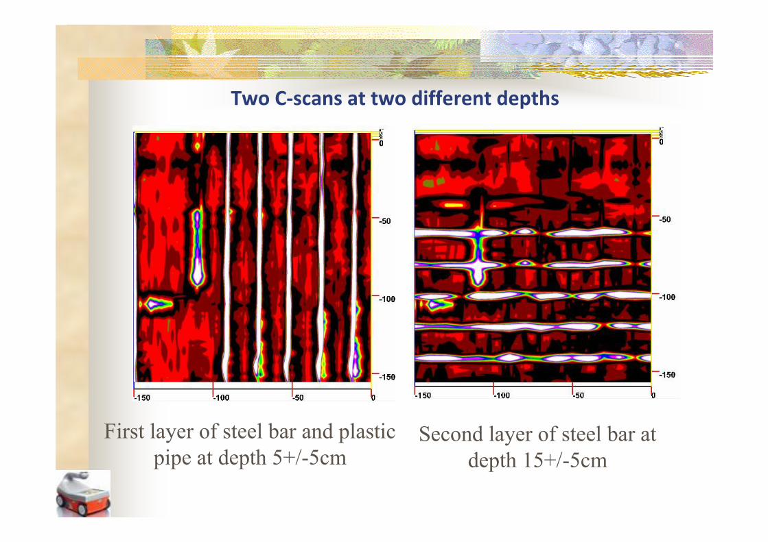
Two C-scans at two different depths
First layer of steel bar and plastic Second layer of steel bar at pipe at depth 5+/5cm depth 15+/5cm
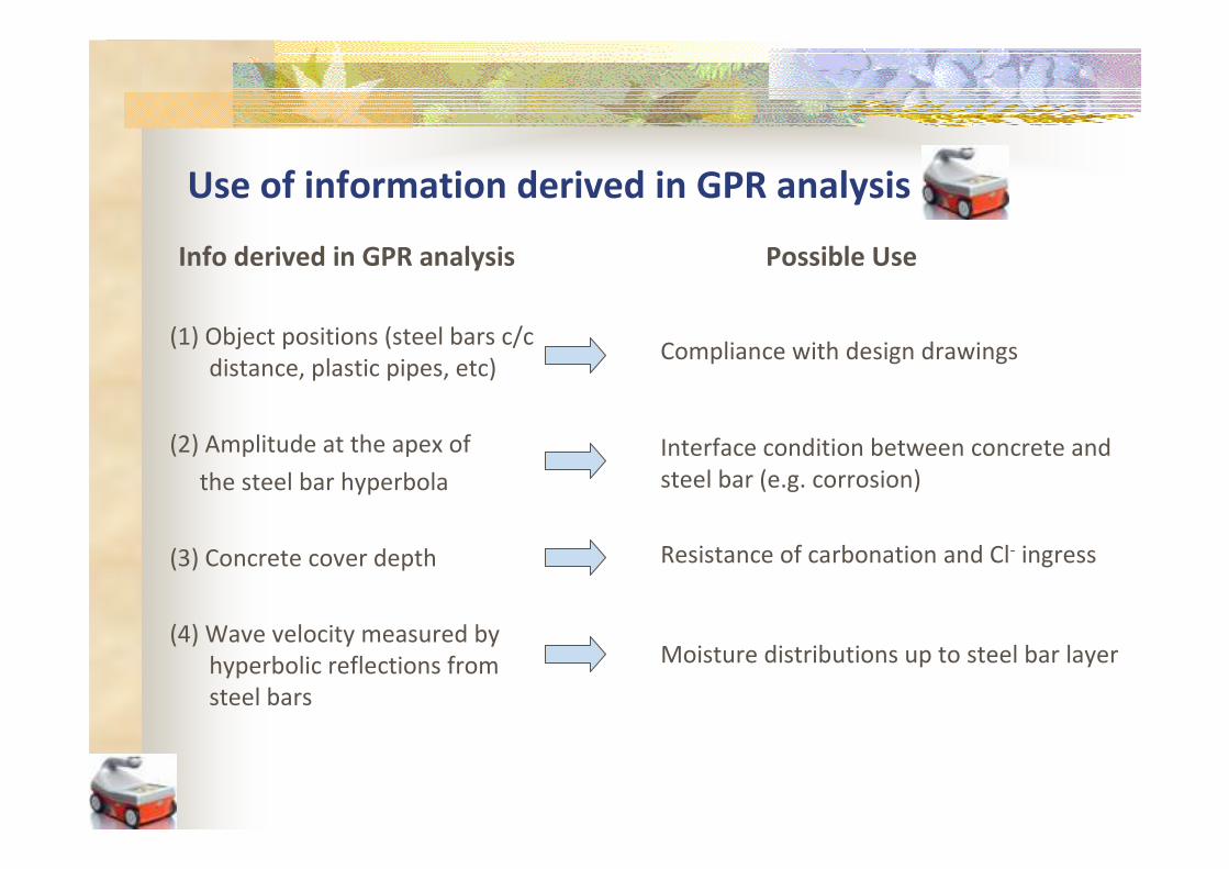
Use of information derived in GPR analysis
Info derived in GPR analysis
(1) Object positions (steel bars c/c
distance, plastic pipes, etc)
(2) Amplitude at the apex of
the steel bar hyperbola
(3) Concrete cover depth
(4) Wave velocity measured by
hyperbolic reflections from
steel bars
Possible Use
Compliance with design drawings
Interface condition between concrete and
steel bar (e.g. corrosion)
Resistance of carbonation and Cl- ingress
Moisture distributions up to steel bar layer
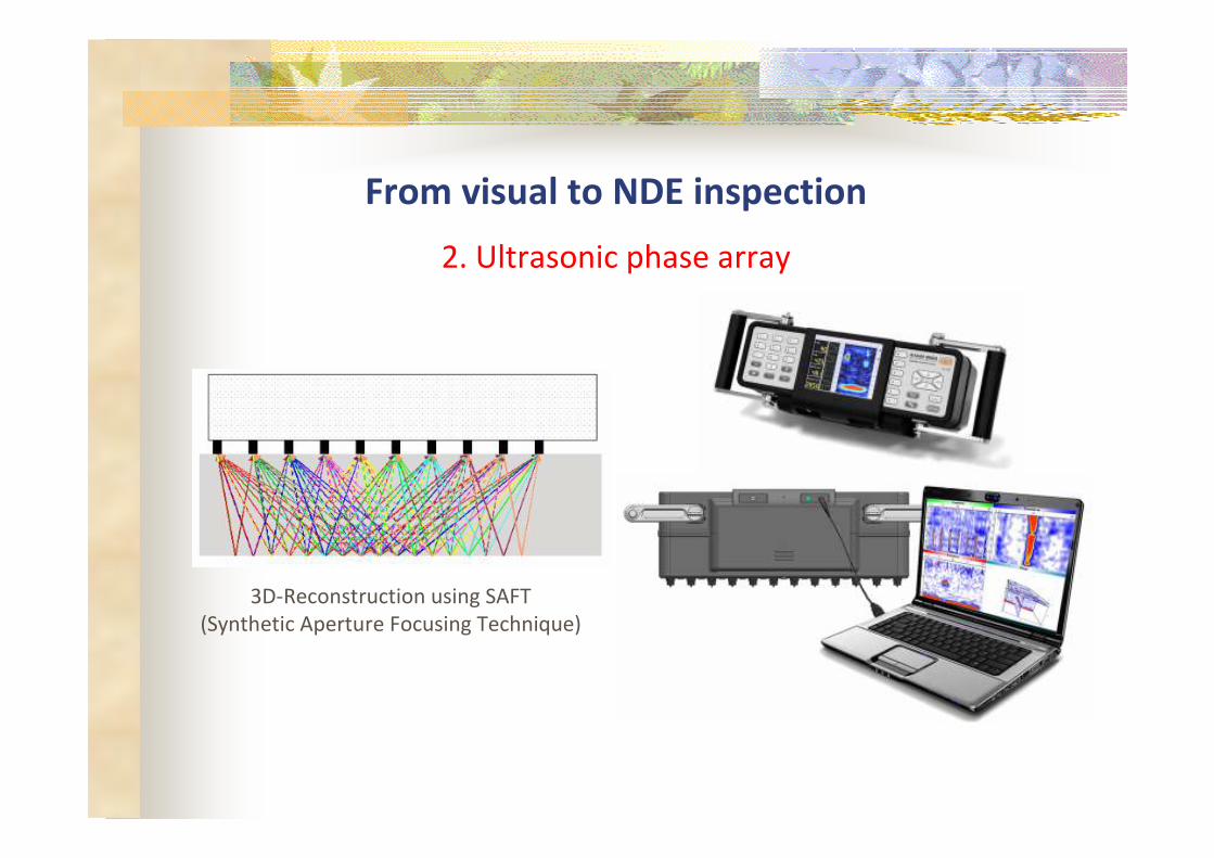
From visual to NDE inspection
2. Ultrasonic phase array
3D-Reconstruction using SAFT
(Synthetic Aperture Focusing Technique)
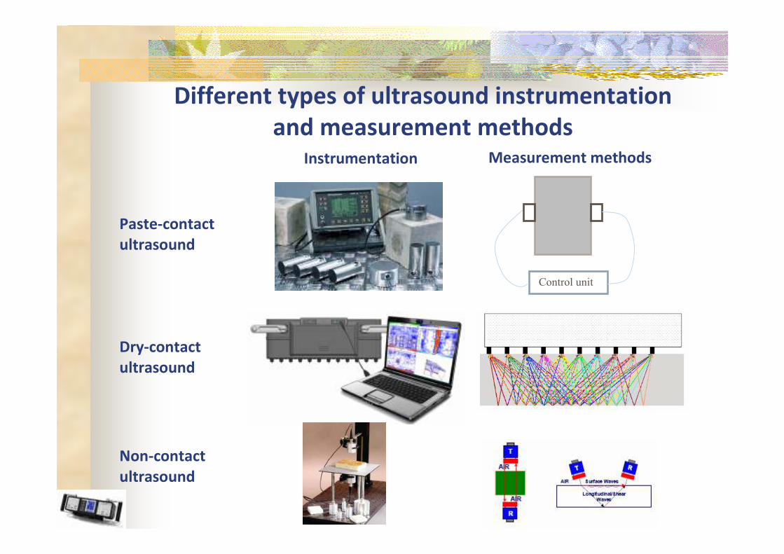
Different types of ultrasound instrumentation
and measurement methods
Paste-contact
ultrasound
Dry-contact
ultrasound
Non-contact
ultrasound
Instrumentation Measurement methods
Control unit
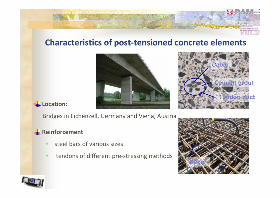
Characteristics of post-tensioned concrete elements
Location:
Bridges in Eichenzell, Germany and Viena, Austria
Reinforcement
� steel bars of various sizes
� tendons of different pre-stressing methods Rebar
Cable
Cement grout
Tendon duct
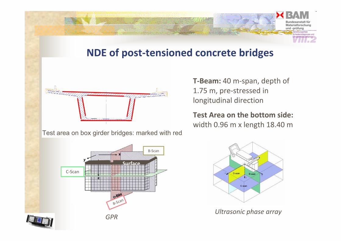
NDE of post-tensioned concrete bridges
Test area on box girder bridges: marked with red
Surface
C-Scan
B-Scan
B-Scan
GPR Ultrasonic phase array
T-Beam: 40 m-span, depth of
1.75 m, pre-stressed in
longitudinal direction
Test Area on the bottom side:
width 0.96 m x length 18.40 m
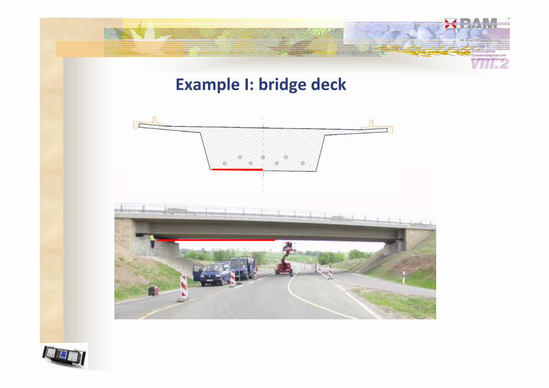
Example I: bridge deck

Result: C-scan in the depth range of
z = 20 – 40cm of bridge deck
Tendon duct 4
Tendon duct 2
Tendon duct 3
Tendon duct 1 X in mm
Cscan
Bscan about the whole
length in the depth range of z = 20 – 40 cm of 18.40 m
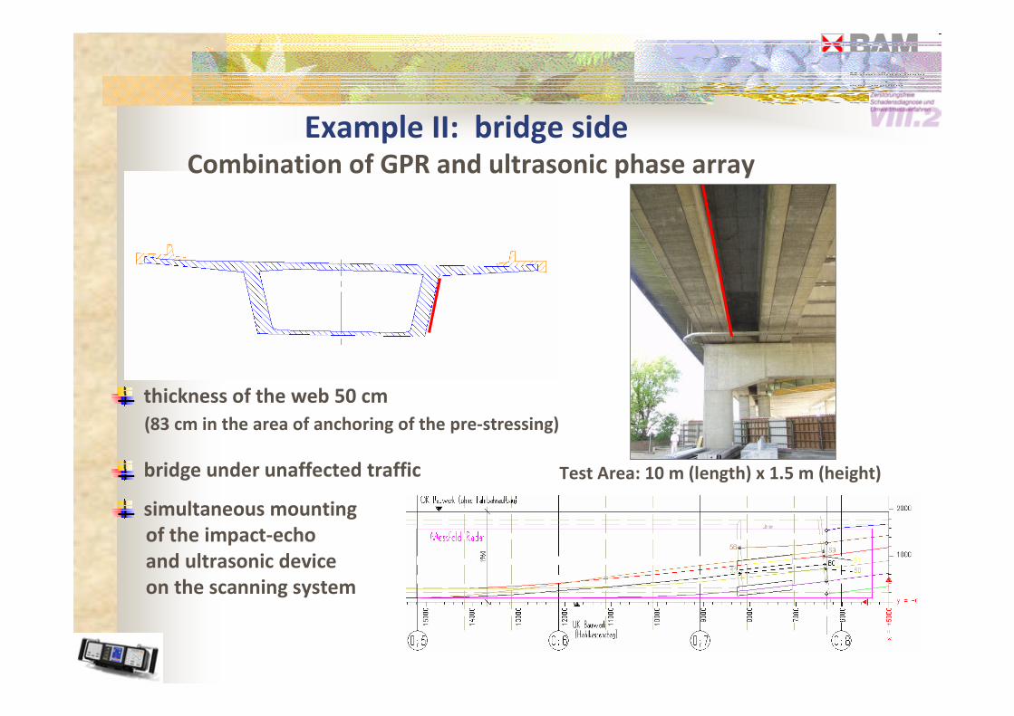
Test Area: 10 m (length) x 1.5 m (height)
thickness of the web 50 cm
(83 cm in the area of anchoring of the pre-stressing)
bridge under unaffected traffic
simultaneous mounting
of the impact-echo
and ultrasonic device
on the scanning system
Example II: bridge side Combination of GPR and ultrasonic phase array
He
igh
t y
in
cm
60
20
1
50
10
0
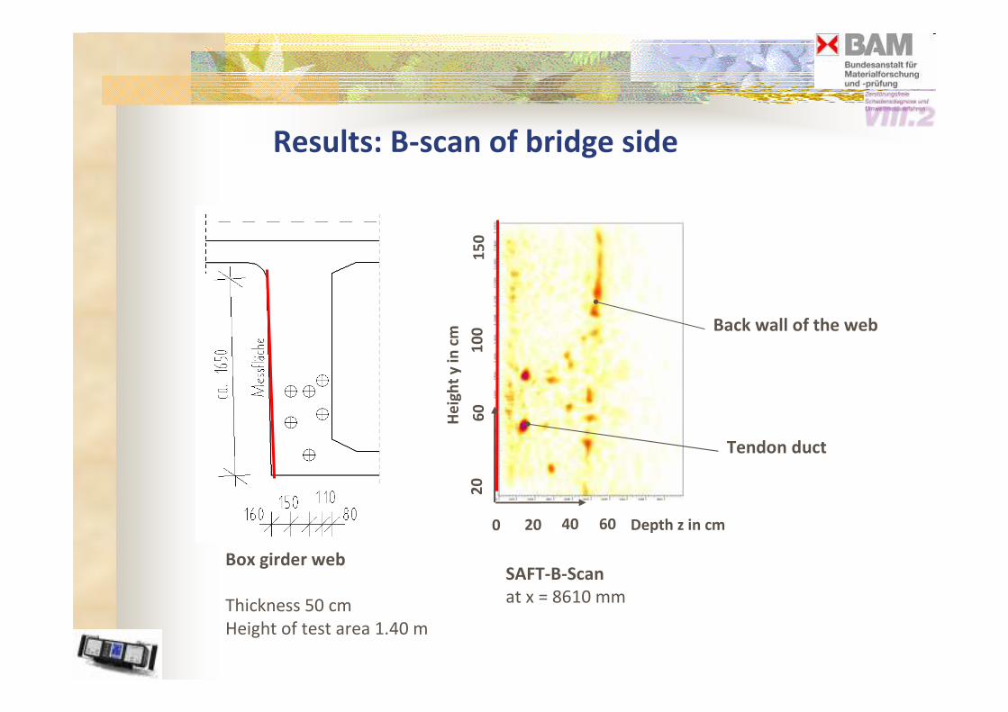
Results: B-scan of bridge side
Back wall of the web
Tendon duct
0 20 40 60 Depth z in cm
Box girder web SAFT-B-Scan
at x = 8610 mm Thickness 50 cm
Height of test area 1.40 m
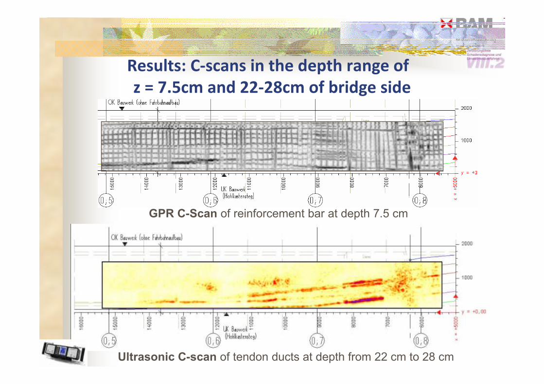
Results: C-scans in the depth range of
z = 7.5cm and 22-28cm of bridge side
GPR CScan of reinforcement bar at depth 7.5 cm
Ultrasonic Cscan of tendon ducts at depth from 22 cm to 28 cm

Cscan data fusion of GPR and ultrasonic signals
Surface
C-Scan
B-Scan
B-Scan
Ultrasonic phase array GPR
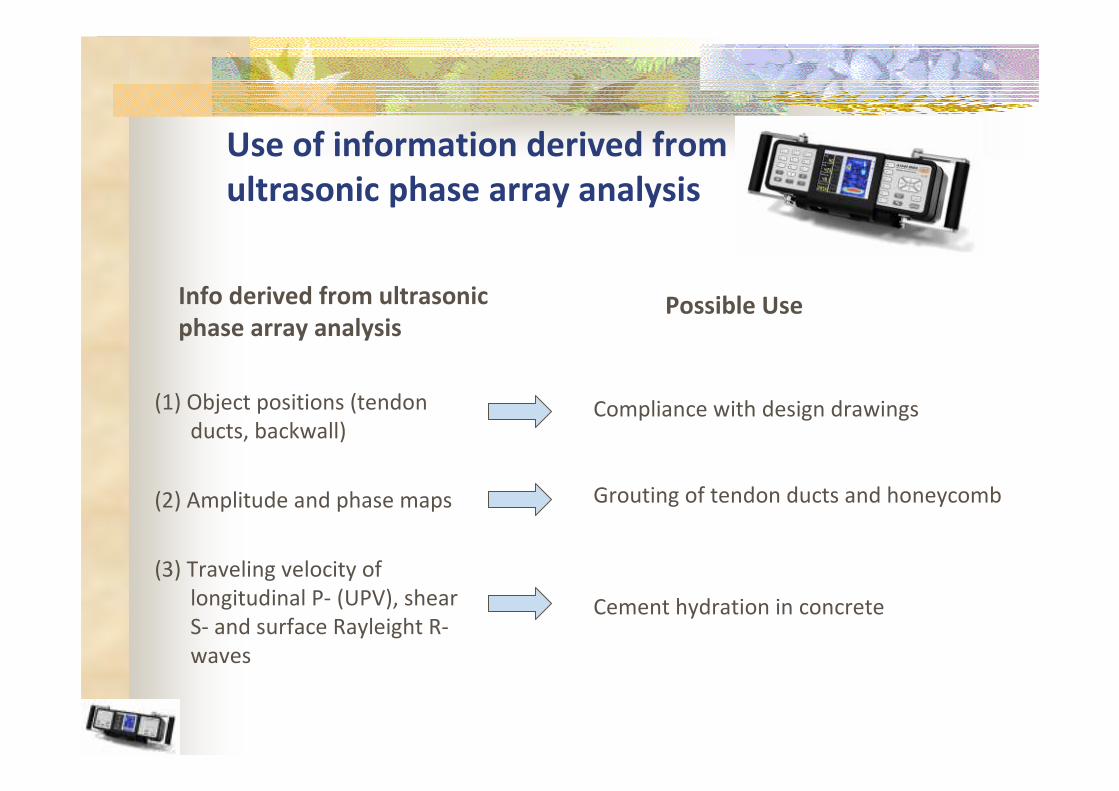
Use of information derived from
ultrasonic phase array analysis
Info derived from ultrasonic Possible Use phase array analysis
(1) Object positions (tendon Compliance with design drawings ducts, backwall)
(2) Amplitude and phase maps Grouting of tendon ducts and honeycomb
(3) Traveling velocity of
longitudinal P- (UPV), shear Cement hydration in concrete S- and surface Rayleight R-
waves
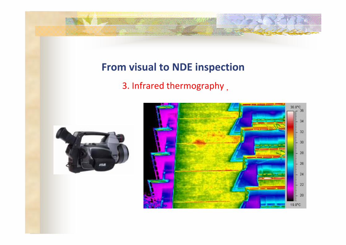
From visual to NDE inspection�
3. Infrared thermography�

Qualitative measurement of tile debond from buildings
by infrared thermography
Temperature distributions obtained by
infrared thermo-imager
Visual photo
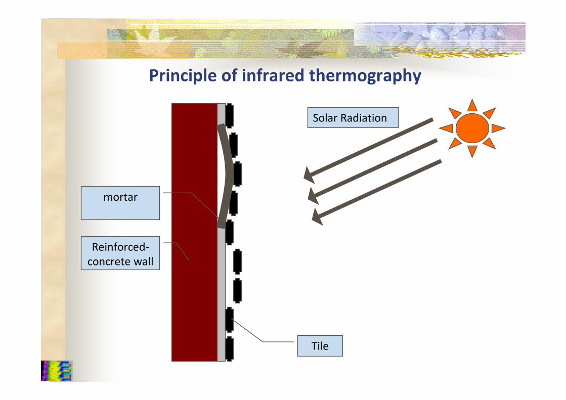
Reinforced-
concrete wall
mortar
Tile
Solar Radiation
Principle of infrared thermography
How to define a defect?
�
BS EN 13187:1998 Thermal performance of buildings -
Qualitative detection of thermal irregularities in building
envelopes - Infrared method
The temperature distribution shall be evaluated from the thermograms.
If this temperature distribution differs from that expected, this shall be
noted. If the irregularities cannot be explained on the basis of
1. the design of the envelope in accordance with the drawings, or
2. effects of heat sources, or
3. cannot be attributed to variations in emissivity, or
4. to the value of the coefficient of heat transfer,
then the irregularity shall be stated as a defect.
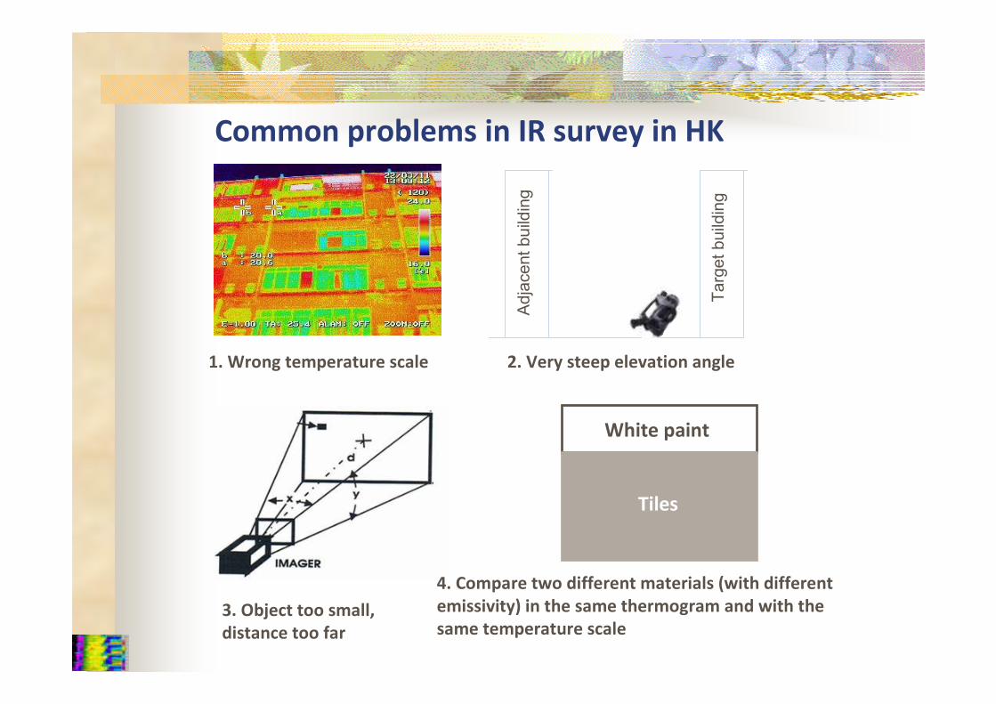
Common problems in IR survey in HK
1. Wrong temperature scale 2. Very steep elevation angle
3. Object too small,
distance too far
4. Compare two different materials (with different
emissivity) in the same thermogram and with the
same temperature scale
White paint
Tiles
Target building
Adjacent building
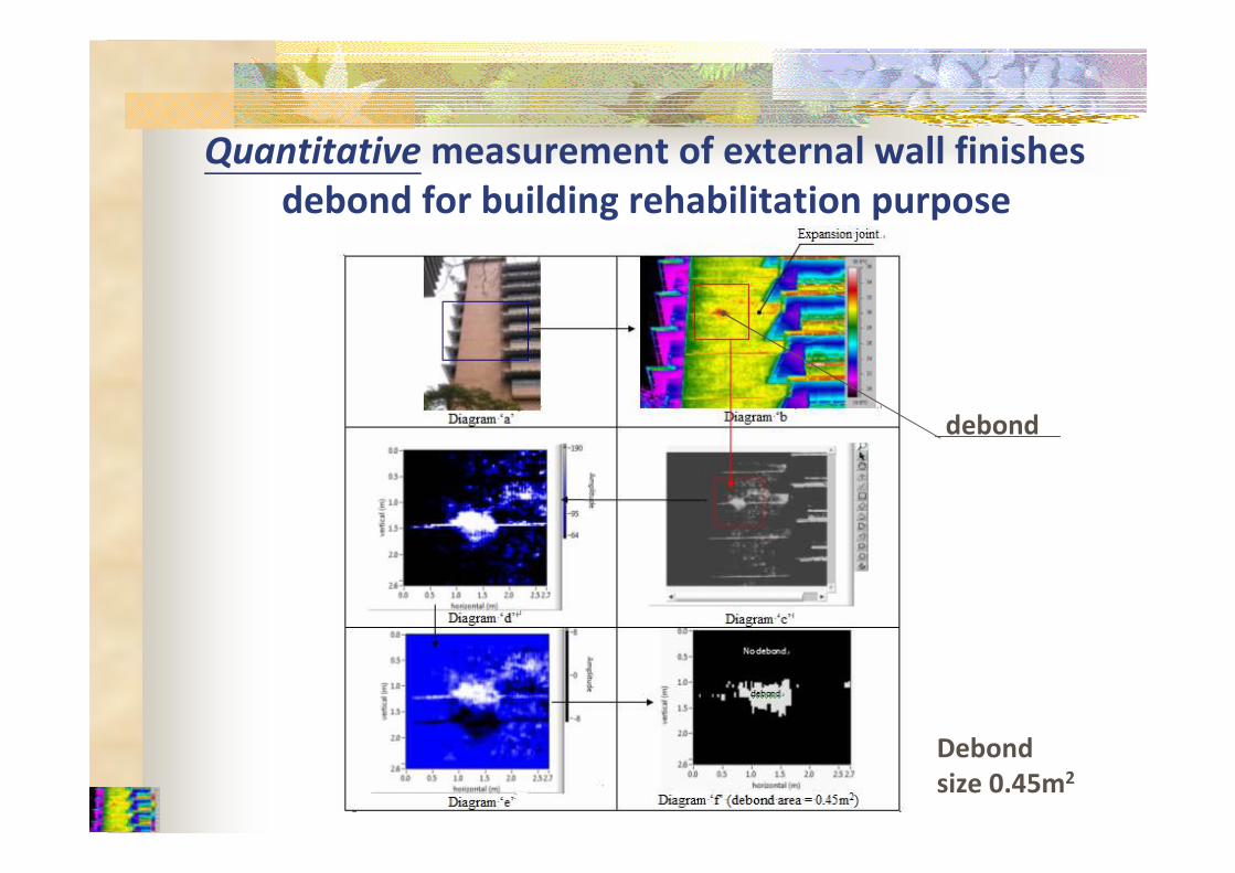
Quantitative
debond
measurement of external wall finishes
debond for building rehabilitation purpose
Debond
size 0.45m2
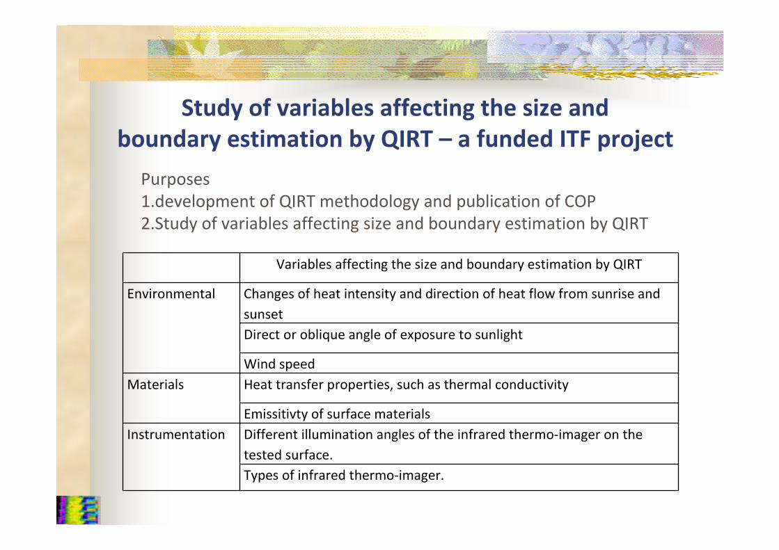
Study of variables affecting the size and
boundary estimation by QIRT – a funded ITF project
Variables affecting the size and boundary estimation by QIRT
Environmental Changes of heat intensity and direction of heat flow from sunrise and
sunset
Direct or oblique angle of exposure to sunlight
Wind speed
Materials Heat transfer properties, such as thermal conductivity
Emissitivty of surface materials
Instrumentation Different illumination angles of the infrared thermo-imager on the
tested surface.
Types of infrared thermo-imager.
Purposes
1.development of QIRT methodology and publication of COP
2.Study of variables affecting size and boundary estimation by QIRT
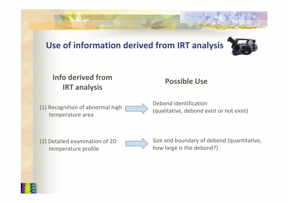
Use of information derived from IRT analysis
Info derived from Possible Use
IRT analysis
Debond identification (1) Recognition of abnormal high
(qualitative, debond exist or not exist)temperature area
(2) Detailed examination of 2D Size and boundary of debond (quantitative,
temperature profile how large is the debond?)
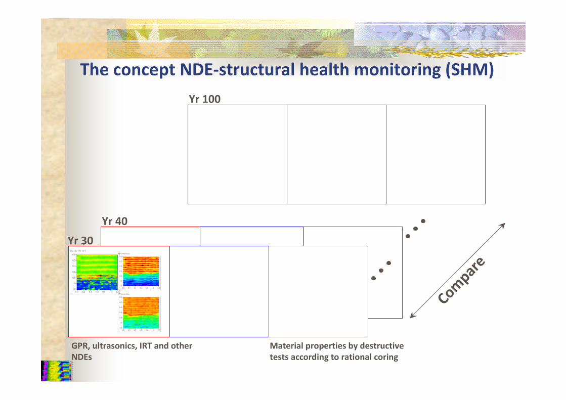
GPR, ultrasonics, IRT and other
NDEs
1 .2
0 .0
0 .2
0 .4
0 .6
0 .8
1 .0
1 .20 .0 0 .2 0 .4 0 .6 0 .8 1 .0
Re fl. to DW TTT
1 .2
0 .0
0 .2
0 .4
0 .6
0 .8
1 .0
1 .20 .0 0 .2 0 .4 0 .6 0 .8 1 .0
DW a m p litu d e
1 .2
0 .0
0 .2
0 .4
0 .6
0 .8
1 .0
1 .20 .0 0 .2 0 .4 0 .6 0 .8 1 .0
DW p e a k fre q
Yr 30
Yr 40
Yr 100
Material properties by destructive
tests according to rational coring
The concept NDE-structural health monitoring (SHM)
erapmoC
Two major difficulties of NDE techniques and
interpretation
Object identifications and location mapping are mature.
But sensor types, multi-dimensional signal processing and
variation of material properties make NDE interpretation of
material properties not straight-forward. Signal inversion
(processing) in this context is still a big subject of research.
The properties measured are not directly related to
engineering properties, e.g. higher ultrasonic pulse velocity is
related to but not always implies high concrete strength.
Accreditation of
Diagnostic Tests on Concrete
presented by
Dr Fiona W.Y. CHANHong Kong Accreditation Service (HKAS)
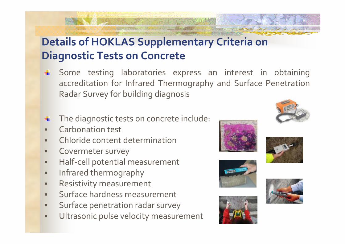
Details of HOKLAS Supplementary Criteria on
Diagnostic Tests on Concrete
Some testing laboratories express an interest in obtaining
accreditation for Infrared Thermography and Surface Penetration Radar Survey for building diagnosis
The diagnostic tests on concrete include:
� Carbonation test
� Chloride content determination
� Covermeter survey
� Half-cell potential measurement� Infrared thermography
� Resistivity measurement
� Surface hardness measurement
� Surface penetration radar survey
� Ultrasonic pulse velocity measurement
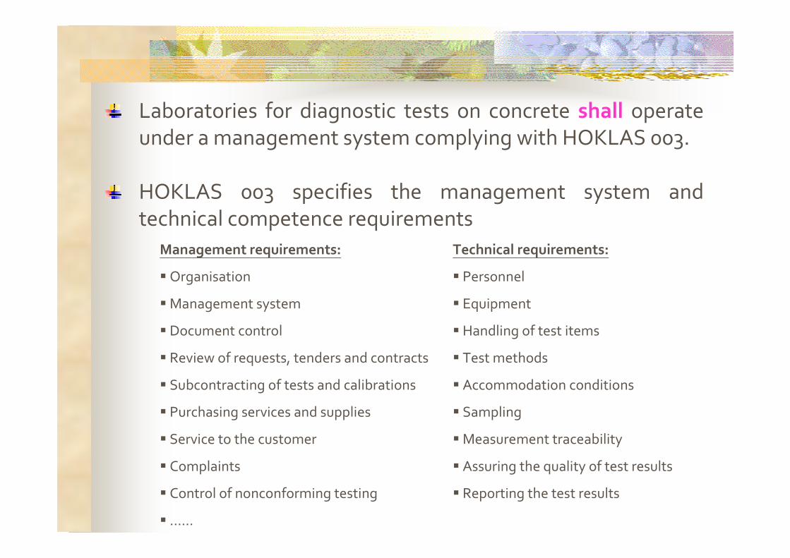
Laboratories for diagnostic tests on concrete shall operate under a management system complying with HOKLAS 003.
HOKLAS 003 specifies the management system and technical competence requirements
Management requirements: Technical requirements:
� Organisation
� Management system
� Document control
� Review of requests, tenders and contracts
� Subcontracting of tests and calibrations
� Purchasing services and supplies
� Service to the customer
� Complaints
� Control of nonconforming testing
� ……
� Personnel
� Equipment
� Handling of test items
� Test methods
� Accommodation conditions
� Sampling
� Measurement traceability
� Assuring the quality of test results
� Reporting the test results

Details of HOKLAS Supplementary Criteria on
Diagnostic Tests on Concrete (cont’d)
HOKLAS SC No.19 gives specific requirements with respect to the followings:
� Personnel� Equipment & calibration
� Test methods� Handling of test items & records
� Strengthening of supervision� Measurement uncertainty
� Proficiency testing

Details of HOKLAS Supplementary Criteria on
Diagnostic Tests on Concrete (cont’d)
Requirements on personnel
� Approved signatory (Infared Thermography & Surface Penetration Radar)
� Approved test operators (Infared Thermography &
Surface Penetration Radar)
� International qualification or completion of
specified training course
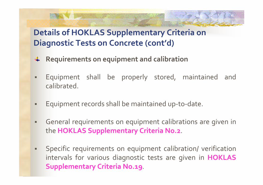
Details of HOKLAS Supplementary Criteria on
Diagnostic Tests on Concrete (cont’d)
Requirements on equipment and calibration
� Equipment shall be properly stored, maintained and
calibrated.
� Equipment records shall be maintained up-to-date.
� General requirements on equipment calibrations are given in the HOKLAS Supplementary Criteria No.2.
� Specific requirements on equipment calibration/ verification intervals for various diagnostic tests are given in HOKLAS
Supplementary Criteria No.19.
Details of HOKLAS Supplementary Criteria on
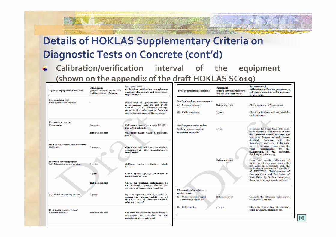
Diagnostic Tests on Concrete (cont’d)Calibration/verification interval of the equipment
(shown on the appendix of the draft HOKLAS SC019)
Details of HOKLAS Supplementary Criteria on
Diagnostic Tests on Concrete (cont’d)
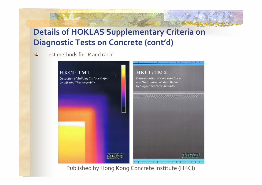
Test methods for IR and radar
Published by Hong Kong Concrete Institute (HKCI)
Details of HOKLAS Supplementary Criteria on
Diagnostic Tests on Concrete (cont’d)
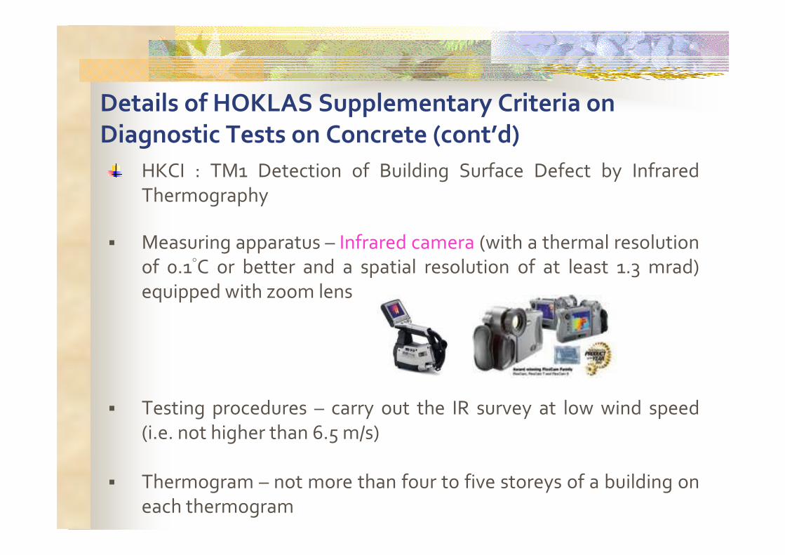
HKCI : TM1 Detection of Building Surface Defect by Infrared
Thermography
� Measuring apparatus – Infrared camera (with a thermal resolution of 0.1°C or better and a spatial resolution of at least 1.3 mrad)
equipped with zoom lens
� Testing procedures – carry out the IR survey at low wind speed
(i.e. not higher than 6.5 m/s)
� Thermogram – not more than four to five storeys of a building on
each thermogram
Details of HOKLAS Supplementary Criteria on
Diagnostic Tests on Concrete (cont’d)
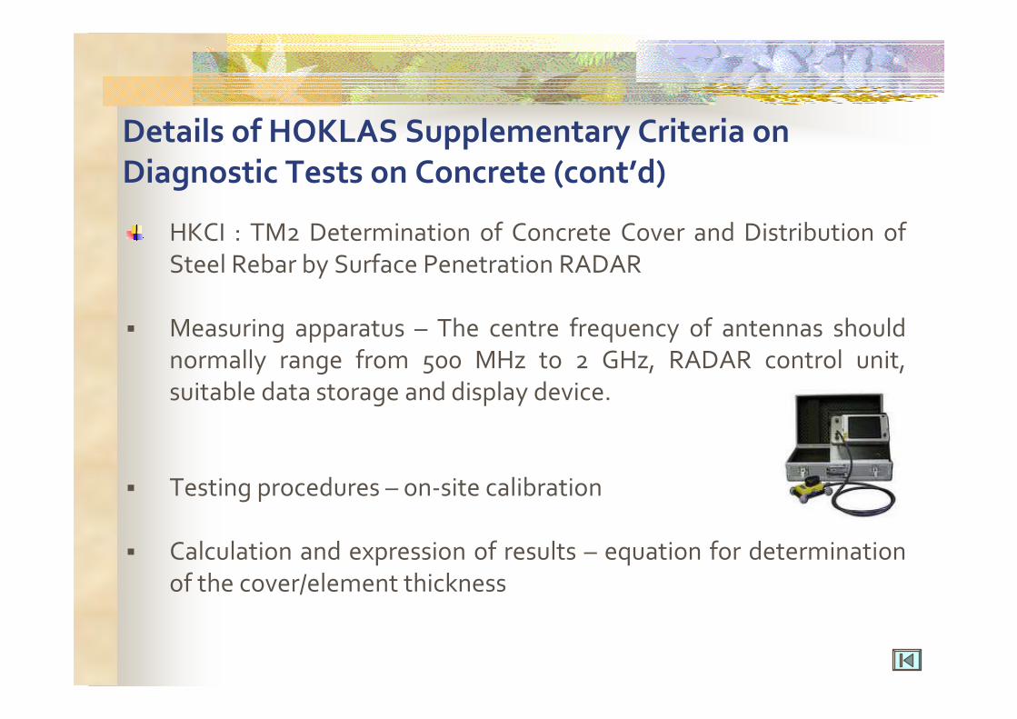
HKCI : TM2 Determination of Concrete Cover and Distribution of
Steel Rebar by Surface Penetration RADAR
� Measuring apparatus – The centre frequency of antennas should normally range from 500 MHz to 2 GHz, RADAR control unit,
suitable data storage and display device.
� Testing procedures – on-site calibration
� Calculation and expression of results – equation for determination
of the cover/element thickness
Details of HOKLAS Supplementary Criteria on
Diagnostic Tests on Concrete (cont’d)
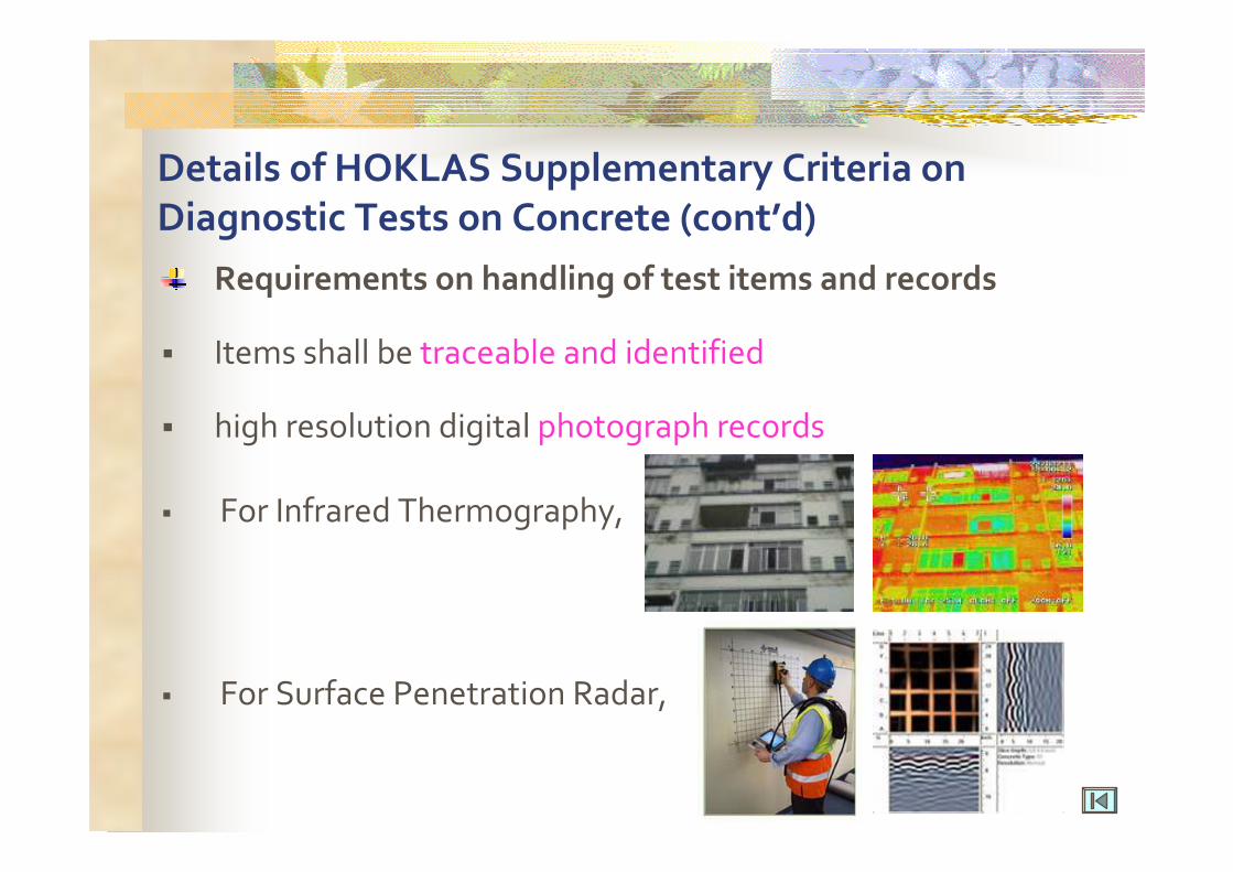
Requirements on handling of test items and records
� Items shall be traceable and identified
� high resolution digital photograph records
� For Infrared Thermography,
� For Surface Penetration Radar,
Details of HOKLAS Supplementary Criteria on
Diagnostic Tests on Concrete (cont’d)
Requirements on strengthening of supervision
HOKLAS Supplementary Criteria No. 36
Construction Materials Test Category – Additional Accreditation Requirements
� ensure effective supervision.
� undue pressure� frequent unannounced on-site visits
Details of HOKLAS Supplementary Criteria on
Diagnostic Tests on Concrete (cont’d)
Requirements on measurement uncertainty
� The laboratory shall have procedures for estimating
uncertainty of measurement.
� All the significant components of uncertainty for each test shall be identified.
� If requested by the client, the laboratory needs to report the
uncertainty of measurement in HOKLAS endorsed reports.
Details of HOKLAS Supplementary Criteria on
Diagnostic Tests on Concrete (cont’d)
Requirements on proficiency testing
� The aim of proficiency testing schemes is to give a way for a
laboratory to monitor its performance against both its own requirements and the performance of other laboratories.
� Proficiency testing programme on Infrared Thermography
and Surface Penetration Radar will be arranged for all the applicants.

Hong Kong Accreditation Service
(HKAS)
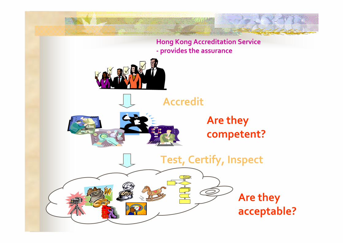
Are they
acceptable?
Hong Kong Accreditation Service
- provides the assurance
Are they
competent?
Test, Certify, Inspect
Accredit
��������
��������
Start
HKAS Objectives
Support the development of the testing and certification industry
Upgrade the standard of the industry
Promote confidence in Hong Kong’s testing,
certification and inspection services
Facilitate international trade
Support local community
A service provided by Government through the Innovation and Technology Commission
Participation is voluntary
Based on international standards
Rigorous assessment and monitoring
International recognition through mutual recognition arrangements
Independent and impartial
Features of HKAS Accreditation
Tailored for local conditions
Accreditation
Accreditation – assurance of the competence of laboratories, inspection bodies and certification bodies to carry out their testing, certification and inspection services
Through rigorous assessment and monitoring
� Reassessments
� Surveillance
� Monitoring of changes
� Complaints
� Proficiency Testing / Inter-laboratory Comparison Study
Criteria based on International Standards
How Accreditation and HKAS can help?
Give assurance on the reliability of testing and certification service
A tool for regulators and other parties to use private sector testing and certification service in critical missions
HKAS accreditation are tailored made and continuously
improved to provide enhanced reliability under local conditions
Help testing and certification industry to improve and expand their markets
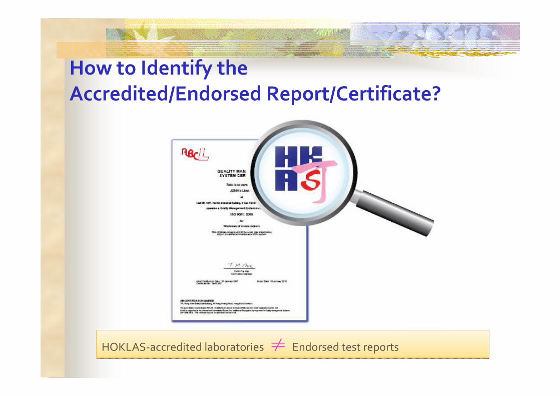
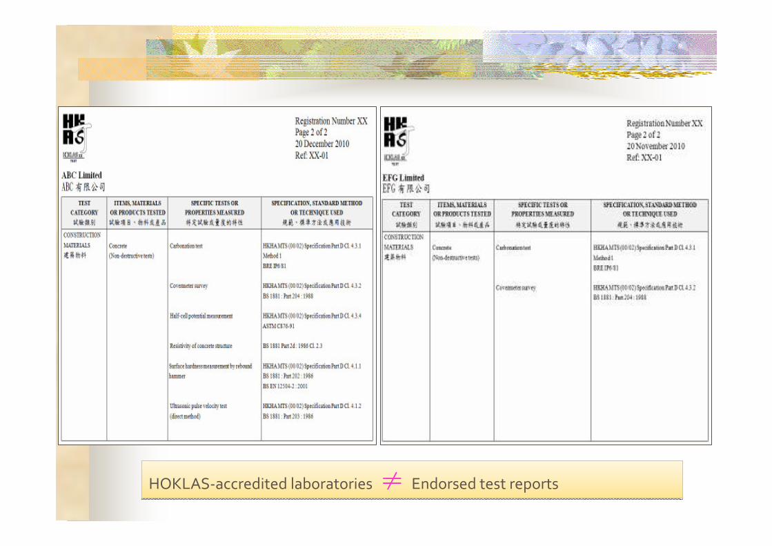
How to Identify the
Accredited/Endorsed Report/Certificate?
HOKLAS-accredited laboratories ≠≠≠≠ Endorsed test reportsHOKLAS-accredited laboratories ≠≠≠≠ Endorsed test reports
HOKLAS-accredited laboratories ≠≠≠≠ Endorsed test reportsHOKLAS-accredited laboratories ≠≠≠≠ Endorsed test reports
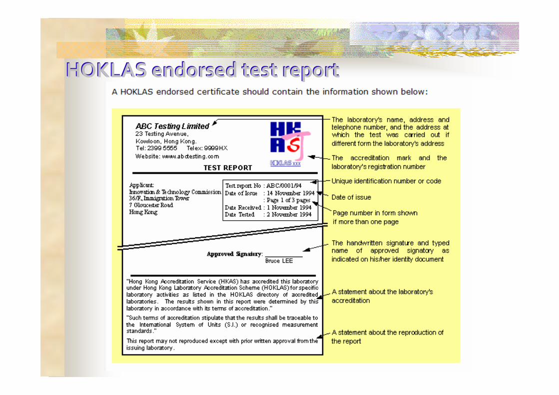
HHOOKKLLAASS en endordorssed ted tesestt r reporeportt

Please visit our website at
www.hkas.gov.hk
To look for accredited laboratories and
more information?
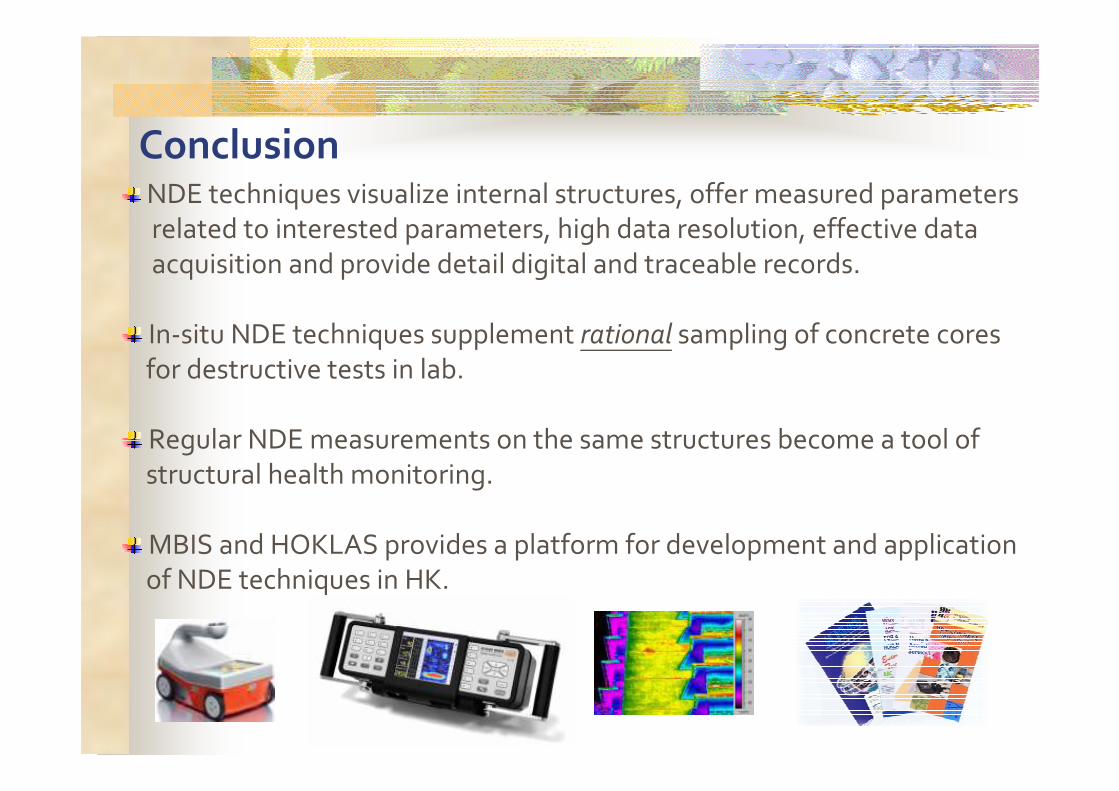
ConclusionNDE techniques visualize internal structures, offer measured parameters related to interested parameters, high data resolution, effective data
acquisition and provide detail digital and traceable records.
In-situ NDE techniques supplement rational sampling of concrete cores
for destructive tests in lab.
Regular NDE measurements on the same structures become a tool of
structural health monitoring.
MBIS and HOKLAS provides a platform for development and applicationof NDE techniques in HK.