nomenclature, symbols, units and their usage in
TRANSCRIPT
INTERNATIONAL UNION OFPURE AND APPLIED CHEMISTRY
DIVISION OF ANALYTICAL CHEMISTRY
COMMISSION ON SPECTROCHEMICAL AND OTHEROPTICAL PROCEDURES FOR ANALYSES
NOMENCLATURE, SYMBOLS,UNITS AND THEIR USAGE IN
SPECTROCHEMICAL ANALYSIS—I.
General Atomic Emission Spectroscopy
Adopted by the IUPAC Council at Washington, DC, USA,during 21—23 July 1971
LONDON
BUTTERWORTHS

ANALYTICAL CHEMISTRY DIVISION
COMMISSION ON SPECTROCHEMICAL AND OTHEROPTICAL PROCEDURES FOR ANALYSESt
NOMENCLATURE, SYMBOLS, UNITS AND THEIRUSAGE IN SPECTROCHEMICAL ANALYSIS—I.
GENERAL ATOMIC EMISSION SPECTROSCOPY
CONTENTSPAGF
I. FOREWORD 655
II. GENERAL RECOMMENDATIONS AND PRACTICES 657
III. TERMS AND SYMBOLS FOR PHYSICAL QUANTITIES IN GENERAL USE 6583.1 Basic physical quantities 6583.2 Other physical quantities 660
IV. TERMS, SYMBOLS AND UNITS RELATED TO RADIANT ENERGY 660
V. TERMS AND SYMBOLS FOR THE DESCRIPTION OF SPECTROGRAPHICINSTRUMENTS 6625.1 Geometrical quantities 6625.2 Optical quantities 6635.3 Quantities related to the transport of radiant energy 664
VI. TERMS AND SYMBOLS RELATED TO THE ANALYTICAL PROCEDURES 6646.1 Qualitative terms concerning the sample 6646.2 Quantitative terms concerning the sample 6656.3 Terms concerning the procedure 665
VII. TERMS AND SYMBOLS RELATED TO FUNDAMENTAL PROCESSESOCCURRING IN LIGHT (EXCITATION) SOURCES 6667.1 General rules 6667.2 Physical constants and properties of particles 6677.3 Terms, symbols and units for measurable quantities 6677.4 Conversion factors 6687.5 Electrical terms 6697.6 Special terms 6697.7 Classification of additives 670
Chairman: V. A. Fassel (USA); Secretary: B. F. Scribner (USA); Members: C. Th. J.Alkemade (Netherlands), L. S. Birks (USA), E. PIko (Czechoslo akia), J. P. Robin (France)J. D. Winefordner (USA), A. C. Menzies (UK); Associate Members: H. Kaiser (Germany),A. Kvalheim (Norway). I. Rubeika (Czechoslovakia), A. Strasheim (South Africa)
653

VIII. PHOTOGRAPHIC INTENSITY MEASUREMENTS (PHOTOGRAPHIC
PHOTOMETRY) 6718.1 Introduction 6718.2 Outline of the measuring procedure 6718.3 Mathematical treatment of measured values for T 6718.4 Practical calibration of a photographic emulsion 673
APPENDIX A: General principles of nomenclature standardization 674
APPENDIX B: Application of the concept of optical conductance 677
654
I. FOREWORDThe purpose of this document is to propose a consistent nomenclature
for workers in spectrochemical analysis. Many of the terms have alreadybeen defined in several nomenclature documents, especially those developedby IUPAC (International Union of Pure and Applied Chemistry), IUPAP(International Union of Pure and Applied Physics) and ASTM (AmericanSociety for Testing Materials). The fact that many of the symbols, units,nomenclature and definitions previously recommended are repeated in thisdocument demonstrates that the nomenclature of a specific field, i.e. spectro-chemical analysis, is deeply rooted in the general nomenclature of chemistryand physics. However, the adaptation of a general system to a specializedfield requires a careful selection of general terms and the addition of newones. In a few cases, it was found necessary to deviate from symbols previ-ously recommended in order to avoid using the same symbol for differentquantities. Even in a restricted field, the same symbol may have differentmeanings, e.g. the letter cmay stand for the speed of light or for concentrationdepending on the context. In some instances, the Commission has favouredterms which have already been accepted through long usage, though logicwould suggest a different terminology. Such terms were accepted only whenno misunderstanding may result.
It is not the intention of this report to provide an exhaustive list of termsbut rather to present a short list in the hope of securing agreement over alimited field. This report is occasionally cast in narrative form and includesbrief explanatory notes. This has been done in cases where the state of the arthas not yet achieved a uniform treatment of the subject in question.
The first part of this report is concerned with some general recommenda-tions, while the remainder is concerned with more detailed aspects. A state-ment by ASTM (American Society for Testing Materials) on general principlesof nomenclature standardization is reprinted as an appendix, with thegenerous permission of ASTM. The Commission endorses the generalprinciples of this statement, while differing in detail on some of the examples.
There are several important fields of spectrochemical analysis not treatedin this document but for which agreement on nomenclature is urgentlyrequired. Among these are the classification and description of the lightsources, and nomenclature for flame atomic absorption, emission, andfluorescence spectroscopy, as well as x-ray spectroscopy. These and otheritems are on the programme of the Commission, but it was felt that the pub-lication of this first set of recommendations should not be delayed byaiming at too high a degree of completeness.
Some remarks about the arrangement of the material in this documentare appropriate. Some chapters start with a list of terms and symbols,
1 In particular nothing in this document is in conflict with the Manual of Symbols andTerm inology for Physicochemical Quantities and Units prepared by IUPAC Commission 1.1 forthe Division of Physical Chemistry.
Often it might be more accurate to speak of a 'radiation source', but the shorter traditionalterm 'light source' is used, it being understood to include invisible radiation.
655
V. A. FASSEL
accompanied—if necessary—by short explanatory notes. This was done forgeneral terms and symbols to facilitate reference. Other chapters are in theform of a glossary of terms and definitions. This document is therefore notarranged in the systematic order of a textbook; it should be used as a com-pendium offering information at different levels and for different purposes.
656
II. GENERAL RECOMMENDATIONS AND PRACTICES2.1 For the description of general quantities used in physics and chemistry,
the nomenclature and symbols adopted in the most recent official documentsof international scientific unions and organizations should be followed. Themost important documents are:1. 'Symbols, Units and Nomenclature in Physics', Document UIP 11 (SUN
65—3); International Union of Pure and Applied Physics [for short,IUPAP 1965]: German edition: Friedr. Vieweg und Sohn, Braunschweig.
2. 'Manual of Physicochemical Symbols and Terminology' (IUPAC), PureApp!. Chem., 21, 1 (1970).
3. Publications of the International Organization for Standardization,Technical Committee 12 (ISO/TC 12).2.2 The symbol for a physical quantity stands for the product of the numeri-
cal value (the measure), which is a pure number, and the unit:
physical quantity = numerical value x unit.
Therefore in equations composed of symbols for physical quantities, unitsshould not appear.
2.3 Symbols for physical quantities should be single letters of the Latinor Greek alphabets printed in inclined or upright type, with or withoutmodifying signs, i.e. subscripts, superscripts and dashes.
Symbols for units of physical quantities should be printed in upright type.Numerals should be printed in upright type.Symbols for chemical elements should be written in upright type.Indices that are symbols for physical quantities should be printed in
inclined type.
(Rules from IUPAP 1965)
2.4 Following the recommendations of IUPAP 1965, a comma should beused in writing decimals, while in English language texts a full stop [period]is permitted. Correspondingly, a cross (x ) should be used for the multiplica-tion sign but only between figures or numbers—not between symbols orunits—while in texts not in English a point in the middle of the line is per-mitted.
Quantities less than unity expressed in decimal form should be writtenwith a zero preceding the decimal sign. To help recognition of large numbers,the figures may be grouped in threes, with a [2-unit] space separating pairsof groups. Commas or full stops should not be used for this purpose.
2.5 In this document logarithms will all be understood as logarithms tobase 10 (symbol: log x = log10 x).
2.6 Certain symbols and letters extensively employed in mathematicalexpressions should be reserved for this purpose. These include: d, (partialdifferential); ö, A (difference); (sum); f (function); ( >, (average), andx, y, z for spatial coordinates, and for the general description of measurablequantities.
657

V. A. FASSEL
2.7 Usage of certain general words in connection with numerical values.'Constant' should only be used for numerical values which really are
constant, particularly for universal constants, such as the gas constant orthe Boltzmann constant. 'Constant' may also be applied to unvaryingmaterial constants, such as the dielectric constant. 'Coefficient' should onlybe used for numerical values which occur in equations of proportionality,for example, 'coefficient of recombination'. (In English these numbers areoften indicated by the termination 'ity', e.g. 'absorptivity'.)
'Index' should only be used to indicate values arising from ratios, e.g.'refractive index'. Since quantities having the dimension unity are concerned,it is sufficient on occasion also to use the simple expression 'number'.
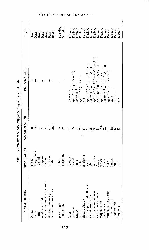
2.8 The 'International System of Units (SI)', is recommended. A summaryof its base and some supplementary and derived units is given in Table 2.1.
SI units for other physical quantities can be derived from the seven baseunits by multiplication or division without introducing numerical factors;this system is coherent. This recommendation is often too rigorously inter-preted. For example, the exclusive use of the SI units (base or derived) is notobligatory when this leads to a unit which is inconvenient in practice [e.g. thefarad is too large; microfarad (pF) and picofarad (pF) are commonly used].Any decimal multiples and fractions of SI units may be used, provided they areclearly stated. There are officially recommended names and symbols forpowers of ten in frequent use. In spectroscopy, the Angstrom is widely usedas unit of wavelength (1 A = 10 "
m). It is a decimal fraction of the SIunit of length, the metre. The Angstrom has a convenient order of magnitudefor the description of optical line spectra and atomic or molecular distances.The nanometer, however, is by one order of magnitude too large, but maybe preferred for optical absorption spectroscopy, where relatively wideabsorption bands must be described.
2.9 Quantitative definitions should, whenever possible, be given by meansof equations.
2.10 In the nomenclature lists which follow, alternatives are occasionallyrecognized. If the alternative symbols are separated by a comma, then bothare equally usable. Separation by a row of dots signifies that the first writtensymbol is preferred.
III. TERMS AND SYMBOLS FOR PHYSICAL QUANTITIES INGENERAL USE
(Extracted from IUPAP 1965)3.1 Basic physical quantities:
lengthmass mtime telectric current Ithermodynamic temperature Tluminous intensity
t Formerly called dimensionless'.The word 'base' was chosen by the Commission Générale des Poids et Mesures with
respect to non-English languages.
658
Tab
le 2
.1. S
umm
ary
of SI
bas
e, s
uppl
emen
tary
an
d de
rive
d un
its
'ID
C) 0 C)
C) z 'ID
'ID
Phys
ical
quan
tity
Nam
e of
SI
unit
Sym
bol
for S
I un
it D
efin
ition
of un
its
Typ
e
leng
th
met
re
m
Bas
e m
ass
kilo
gram
me
kg
- B
ase
time
seco
nd
s B
ase
elec
tric
cur
rent
am
pere
A
—
- B
ase
ther
mod
ynam
ic te
mpe
ratu
re
kelv
in
K
Bas
e lu
min
ous
inte
nsity
ca
ndel
a cd
—
B
ase
amou
nt o
f a s
ubst
ance
m
ole
mo!
B
ase
plan
e ang
le
radi
an
rad
—
Supp
irn.
so
lid a
ngle
st
erad
ian
sr
Supp
lm.
forc
e ne
wto
n N
kg
m s2
D
eriv
ed
pres
sure
pa
scal
Pa
kg
m1
s2( =
N r
n2)
Der
ived
en
ergy
jo
ule
J kg
m2 s2
D
eriv
ed
pow
er
wat
t W
kg
m2 s3
( = J
s')
Der
ived
el
ectr
ic c
harg
e co
ulom
b C
A
s
Der
ived
el
ectr
ic p
oten
tial d
iffe
renc
e vo
lt V
kg
m2 s
A
(= J
A—
1 s)
D
eriv
ed
elec
tric
res
ista
nce
ohm
kg
m2 s3
A2
(= V
A—
') D
eriv
ed
elec
tric
con
duct
ance
si
emen
s G
kg
' m2
s3 A
2 ( =
A V
= Q')
Der
ived
el
ectr
ic c
apac
itanc
e fa
rad
F A
2 s4
kg' m
2(=
AsV
1)
Der
ived
m
agne
tic f
lux
web
er
Wb
kg m
2 s2
A1
(= V
s)
Der
ived
in
duct
ance
he
nry
H
kg m
2 2
A2
(= V
A
1 s)
D
eriv
ed
mag
netic
flu
x de
nsity
te
sla
T
kg _
2 A
1 (=
v s
m2)
D
eriv
ed
lum
inou
s flu
x lu
men
Im
cd
sr
Der
ived
ill
umin
atio
n lu
x lx
cd
sr m
2 D
eriv
ed
freq
uenc
y he
rtz
Hz
s D
eriv
ed
V. A. FASSEL
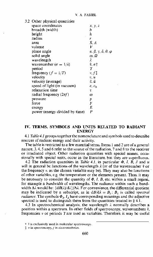
3.2 Other physical quantitiesspace coordinates x, y, zbreadth (width) bheight hradius rarea S. Avolume Vplane angle , f3, y, ö, 0, çosolid angle w, Qwavelength A
wavenumber (tr = 1/A) i, aperiod Tfrequency (f = l/T) v, fvelocity v, uvelocity (average) i5, ü
speed of light (in vacuum) c, c0relaxation timeradial frequency (2irf) co
pressure pforce Fenergy Epower (energy divided by time) P
IV. TERMS, SYMBOLS AND UNITS RELATED TO RADIANTENERGY
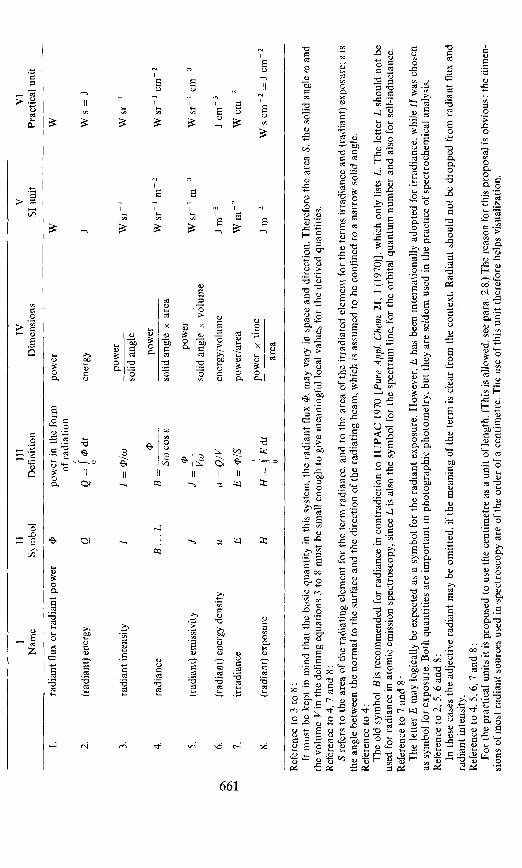
4.1 Table 4.1 groups together the nomenclature and symbols used to describesources of radiant energy and their activity.
The table is restricted to a few essential terms. Items 1 and 2 are of a generalnature, 3, 4, 5 and 6 refer to the source of the radiation, 7 and 8 to the receiveror irradiated object. Other radiation quantities with special names, occa-sionally with special units, occur in the literature, but they are superfluous.
4.2 The radiation quantities in Table 4.1, in particular , I, B, J and uwill in general be functions—of the wavelength A (or of the wavenumber i orthe frequency v, as the chosen variable may be). They may also be functionsof other variables, e.g. the temperature or the elements present. Thus, it maybe necessary to consider the quantity of , I, B, etc. within a small region,for example a bandwidth of wavelengths. The radiance within such a band-width AA would be: {dB(A)/dA}/AA. For convenience, the differential quotientmay be indicated by a subscript, as in dB/dA B; B is called spectralradiance. The symbols , I. have corresponding meanings and the adjectivespectral is used to distinguish them from the quantities treated in §4.1.
4.3 In spectrochemical analysis, the wavelength A normally describes aposition within a spectrum. In other fields of spectroscopy, wavenumbers ,frequencies v or periods Tare used as variables. Therefore, it may be useful
+ is exclusively used in molecular spectroscopy.V in spectroscopy,Jin electrotechnics.
660
II
III
IV
V
VI
Nam
e S\
mbo
l D
efin
ition
D
imen
sion
s SI
uni
t Pr
actic
al u
nit
radi
ant f
lux
or ra
dian
t pow
er
P po
wer
in
the
form
po
wer
W
W
of
radi
atio
n
2.
(rad
iant
) en
ergy
Q
Q
= J
Ii d
t en
ergy
J
W S
J
pow
er
3.
radi
ant i
nten
sity
1
1 =
cI'/
w
W sr
1
W s
r so
lid a
ngle
pow
er
4.
radi
ance
B
... L
B
= —
——
—--
- W
sr_
i m
2 W
sr 1
cm2
Sw co
s E
solid
ang
le x
are
a
pow
er
5.
(rad
iant
) em
issi
vity
J
J = —
.
W s
r m
W
sr
cm
Vw
so
lid a
ngle
x v
olum
e
6.
(rad
iant
) ene
rgy
dens
ity
u u
= Q
/V
ener
gy/v
olum
e J m
3 J
cm
7.
irra
dian
ce
E
E
/S
pow
er/a
rea
W m
2 W
cm
2 1
pow
er x
tim
e 8.
(r
adia
nt) e
xpos
ure
H
H =
E
dt
—
J m
2 W
s cm
2 =
J c
m 2
ar
ea
Ref
eren
ce to
3 to
8
It m
ust b
e ke
pt in
min
d th
at th
e ba
sic
quan
tity
in th
is s
yste
m,
the
radi
ant f
lux , m
ay v
ary
in s
pace
and
dire
ctio
n, T
here
fore
the
are
a S.
the
solid
ang
le cv
and
th
e vo
lum
e V
in t
he d
efin
ing
equa
tions
3 to
8 m
ust b
e sm
all
enou
gh t
o gi
ve m
eani
ngfu
l lo
cal
valu
es fo
r the
der
ived
qua
ntiti
es.
Ref
eren
ce to
4, 7
and
8:
S re
fers
to th
e ar
ea o
f the
radi
atin
g el
emen
t for
the
term
radi
ance
, an
d to
the
area
of
the
irra
diat
ed e
lem
ent f
or th
e te
rms i
rrad
ianc
e and
(rad
iant
) exp
osur
e: c
is
the a
ngle
bet
wee
n th
e nor
mal
to th
e su
rfac
e an
d th
e di
rect
ion
of th
e ra
diat
ing
beam
, w
hich
is a
ssum
ed t
o be
con
fine
d to
a na
rrow
solid
ang
le.
Ref
eren
ce t
o 4:
T
he o
ld sy
mbo
l B
is r
ecom
men
ded
for r
adia
nce i
n co
ntra
dict
ion t
o IU
PAC
197
0 {P
ure
App
i. C
hem
. 21,
1 (1
970)
], w
hich
onl
y lis
ts L
. The
let
ter L
sho
uld
not b
e us
ed f
or ra
dian
ce in
ato
mic
emis
sion
spe
ctro
scop
y, s
ince
L is
als
o th
e sy
mbo
l fo
r the
spe
ctru
m l
ine,
l'or
the
orbi
tal q
uant
um nu
mbe
r and
als
o fo
r sel
f-in
duct
ance
. R
efer
ence
to
7 an
d 8:
T
he le
tter
E m
ay lo
gica
lly b
e ex
pect
ed a
s a
sym
bol
for t
he ra
dian
t exp
osur
e. H
owev
er,
E h
as b
een
inte
rnat
iona
lly ad
opte
d fo
r irr
adia
nce.
whi
le H
was
cho
sen
as s
ymbo
l fo
r exp
osur
e. B
oth
quan
titie
s ar
e im
port
ant i
n ph
otog
raph
ic ph
otom
etry
. but
they
are
sel
dom
use
d in
the
prac
tice o
f' sp
ectr
oche
mic
al
anal
ysis
. R
efer
ence
to
2, 5
, 6 a
nd 8
: In
the
se c
ases
the
adje
ctiv
e ra
dian
t may
be
omitt
ed,
if th
e m
eani
ng o
f the
term
is c
lear
fro
m t
he co
ntex
t. R
adia
nt s
houl
d no
t be d
ropp
ed f
rom
radi
ant f
lux
and
radi
ant i
nten
sity
. R
efer
ence
to
4, 5
, 6, 7
and
8:
For
the
prac
tical
uni
ts it
is p
ropo
sed t
o us
e th
e cen
timet
re as
a u
nit of
leng
th. (
Thi
s is
allo
wed
, se
e pa
ra. 2
.8.)
The
reas
on fo
r thi
s pro
posa
l is
obvi
ous:
the
dim
en-
sion
s of
mos
t rad
iant
sou
rces
use
d in
spec
tros
copy
are
of th
e or
der o
f' a
cent
imet
re.
The
use
of t
his
unit
ther
efor
e hel
ps vi
sual
izat
ion.

V. A. FASSEL
to list here the relationships of bandwidths expressed in different variablesand of the spectral radiation quantities, e.g. the spectral radiant flux J:
Av=c= — Ai/i2 = — cAy/v2 = cAT= — j2 '1 = —V2 /c =
4.4 The different radiation quantities for the black body play an importantrole in spectroscopy as natural standards because they are determined byconstants of nature, temperature and wavelength. They may be distinguishedby an additional superscript, the letter b; for example the spectral radianceof the black body: B.
4.5 If the radiation acts as light, affecting the human eye, the radiationmay be measured and appreciated in a different way, taking into accountnot only the physical but also physiological processes. The technique ofmeasurement of light in this context is called photometry.
Although in modern spectroscopy visual observations and measurementshave become very rare, it seems advisable to give some explanation of photo-metry. There has been much confusion in the past by inappropriate use ofphotometric terms and units in the measurement of radiation quantities.
(a) There is a set of luminous quantities, which correspond to the radiantquantities of Table 4.1. The same symbols are used. If confusion betweenluminous and radiant quantities may occur, subscripts should be added:e (energy) for radiant, v (visible) for the luminous quantities. [It has beenproposed that in cases where the number of quanta has been determinedinstead of the energy, the subscript q might be added.]
(b) A relationship between radiant and luminous quantities has been estab-lished by the definition of the normal eye (standard observer). The normallight-adapted eye is characterized by a wavelength dependent function, the(spectral) luminous efficacy K(2), whose maximum Km occurs at 555 nmand has the value Km = 680 lm/W. The function KL)/Km = V(A) is called(spectral) luminous efficiency. The relation between radiant flux 1e' and theluminous flux is as follows
, v (7 80 nm Iii \ ñb= 1'-m .13 80 nm V V) e, 2For the exact values of Km and VL), the most recent publications from theInternational Commission on Illumination (CIE)t should be consulted.
V. TERMS AND SYMBOLS FOR THE DESCRIPTION OFSPECTROGRAPHIC INSTRUMENTS
5.1 Geometrical quantities—In this section the terms and symbols aredescribed with a spectrograph in mind. The modifications necessary toconsider other forms of spectral apparatus will be self-evident.
5.1.1 In the spectrograph the whole range of spectrum allowed by thedesign of the instrument is recorded on the photographic plate.
t CIE Publication No. 17 (E—1.1) 1970.
662

SPECTROCHEMICAL ANALYSIS—-!
When in place of the photographic plate, direct means are used to measureintensities in the spectrum, the instrument is described as a spectrometer.For example, a thermopile or a photoelectric device may be made to scanthe spectrum in the focal plane, measuring the intensity at each position.
If the focal plane is obstructed except for one slit, the instrument is calleda monochromator. The bandwidth of the spectrum which emerges throughthe exit slit depends inter alia upon the widths of the entrance and exit slits.A monochromator is usually provided with means for altering the meanwavelength of the band transmitted, but there are also fixed monochromators,which then correspond to a filter.
The polychromator is an extension of the monochromator, a number ofexit slits being placed in the focal plane, so allowing a number of discretebands to pass through (for example, to fall upon a number of photomulti-pliers).
5.1.2 Light enters a spectrograph through a slit having a geometricslit-width s and height h.
5.1.3 The light strikes a collimator lens or mirror which has an aperturestop of diameter D, or the aperture stop may have a rectangular clear cross-sectional area S of width D (parallel to the width of the slit) and height Dh.The effective diameter for a non-circular aperture stop of area S, (Deff) 5given by (4S/ir) or (4DDht).
5.1.4 The focal length of the collimator lens or mirror isf and the light-gathering power of the lens is measured by the fnumber which 1Sf /Deff.
5.1.5 The light then encounters a dispersing system (see 5.1.9) and afterdispersion the light enters an objective lens or mirror, where beams ofdifferent wavelengths are focused to form images of the entrance slit atdifferent places along the focal plane.
5.1.6 In order to counteract the variation with wavelength of the focallength f' of the objective lens, it may be necessary to tilt the photographicplate, and the tilt of the plate, 0, is the angle between the normal to the plateand the direction of the camera axis.
5.1.7 The practice of optical designers in distinguishing magnitudes in theimage space from similar ones in the object space by using a prime is adopted,hence thef' used in the previous paragraph. In a monochromator, for ex-ample, the exit slit has width s' and height h'.
5.1.8 The light during passage through an instrument has a beam of widthW, and one may distinguish at times W and Wh.
5.1.9 The dispersing system may be a prism or a series of prisms, and thelength of the total effective prism base is b. The effective base is the differencebetween the lengths, measured within the prisms, of the extreme rays nearthe base and near the apices, respectively. Alternatively, the dispersing systemmay be a diffraction grating, having a total number of rulings, Nr. The numberof grating rulings per unit length is The rulings may possess a blaze-angle f,which is the angle between the operating facet of the grooves and the overallplane of the grating. This results in the grating enhancing the intensity ofwavelengths near to a blaze wavelength A. (The order of the spectrum towhich the blaze refers should be stated.) The order of the spectrum is preferablydenoted by m, although k is accepted.
5.2 Optical quantities—5.2.l The refractive index of a material is n.663

V. A. FASSEL
5.2.2 When a spectral bandwidth is to be indicated in terms of wavelength,the symbol is A). For the width of a spectral line at half-peak intensity—asit appears in a spectrum produced by an instrument—the symbol is &.Thewidth of the line itself as it would be shown by an instrument of very highresolving power can be written as öLL (This includes the natural width,Doppler and Stark effects, pressure broadening, etc). The minimal line widthwhich can be produced by a spectroscopic instrument for reasons of principle(mostly limited by diffraction) is written &A.
The (theoretical) resolving power R0 of a spectroscopic instrument isdefined by R0 = Very often this resolving power R0 cannot be usedor attained for practical reasons (e.g. 6L2 > optical aberrations andnecessity to use a wide slit). In such cases, the (practical) resolution R isdefined by R =
5.2.3 Dispersion dz/d2 is qualified in different ways according to the conceptindicated by z. For example, substitution of z by n gives dn/d2 the dispersionof a material, by angle ço, angular dispersion, while substitution of z by theseparation x of spectral lines gives the linear dispersion.
5.2.4 The reciprocal of the last named quantity is more frequently used,and referred to as the reciprocal linear dispersion. d/dx, and it is commonlyexpressed in A/mm.
5.3 Quantities related to the transport of radiant energy—5.3.1 Three ex-pressions are used to describe how an optical system transmits, reflects orabsorbs radiation. They are optically composite quantities (for example, thetransmission factor of a monochromator) so to indicate this they are calledfactors. cP0 is the radiant flux entering the system. The respective terms are:
transmission factor t =reflection factor p = r/O andabsorption factor =
5.3.2 A little known but useful quantity is the optical conductance G thatdescribes the geometrical restriction of the radiant flux through an instrument(or optical system) by the apertures and the distances separating them. Thisquantity is discussed in detail in Appendix B.
VI. TERMS AND SYMBOLS RELATED TO THE ANALYTICALPROCEDURES
6.1 Qualitative terms concerning the sample—In analytical spectroscopy.material is provided, and from this is taken a sample that is submitted foranalysis. The material has a certain composition, consisting 'of an aggregateof constituents. If the proportion of one constituent predominates, it is referredto as the major constituent. The latter term should be distinguished from thedescription of the character of the material as a whole, e.g. granite, organictissues, solutions, which are referred to as the base. The element sought ordetermined in the sample is the analysis element.
Samples may be transformed into a solution. Here we distinguish betweenthe solvent (for example, water or a mixture of water and alcohol) andconcomitants, which include constituents other than the analysis element inthe solution.
The term matrix refers to the sample, considered as an assemblage of664
SPECTROCHEMICAL ANALYSIS--I
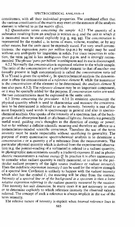
constituents, with all their individual properties. The combined effect thatthe various constituents of the matrix may exert on the measure of the analysiselement is referred to as the matrix effect.
6.2 Quantitative terms concerning the sample—6.2.1 The quantity of asubstance resulting from an analysis is written as q, and the unit in which itis measured must be stated explicitly (e.g. g, mg, tg). The concentration isrepresented by the symbol c, in terms of mass, volume, number, or by anyother means, but the units must be expressly stated. For very small concen-trations, the expression parts per million (p.p.m.) by weight may be usedwithout any ambiguity for impurities in solids. For trace impurities in solu-tion, the term tg/ml is less ambiguous than p.p.m. and is strongly recom-mended. The phrase 'parts per billion' is ambiguous and its use is discouraged.
6.2.2 Normally the concentration is expressed relative to the whole sample.The ratio of the concentration of a particular element to that of another one(usually present in high concentration) is called the concentration ratio (ofX to Y) and is given the symbol Cr. In spectrochemical analysis the denomin-ator is often the concentration of a reference element R, while the numeratoris the concentration of the element to be determined, the analysis element X(see also para. 6.3.2). The reference element may be an important component,or it may be specially added for the purpose. If concentration ratios are used,the two concentrations must be expressed in the same units.
6.3 Terms concerning the procedure—6.3.1 In emission spectroscopy thephysical quantity which is used to characterize and measure the concentra-tion to be determined is referred to as the intensity. Intensity is one of themost frequently used words in spectroscopy in general and also in spectro-chemical analysis. One speaks of the intensity of a spectrum line, of the back-ground, of an absorption band, or of a beam of light etc. Intensity is a generallyuseful word, guiding one's thoughts in the direction of energy or power,but so far without a definite scientific meaning and therefore an offence to anomenclature-minded scientific conscience. Therefore the use of the termintensity must be made respectable without sacrificing its generality. Thepurpose of every quantitative spectrochemical analysis is to determine aconcentration c or a quantity q of a substance from the measurements. Theparticular physical quantity which is derived from the experimental observa-tion (e.g. the pointer-reading of a voltmeter) is related to a radiant quantity,in photographic measurements usually a (radiant) exposure H and in photo-electric measurements a radiant energy Q. In practice it is often unnecessaryto consider what radiant quantity is really measured, or to refer to the par-ticular radiant property of the light source (radiance or radiant intensity).Then the indefinite expression intensity 1 can be used for the relative strengthof a spectral line. Confusion is unlikely to happen with the radiant intensitywhich also has the symbol 1; the meaning will be clear from the context.Intensity of a spectral line or of the background in a spectrum is then a looserelative expression referring to the radiant quantity measured by the receiver.This intensity has unit dimension. In many cases it is not necessary to stateor to determine explicitly to which reference intensity the observed value isreferred. The concept of such a reference is always implicit in the use of theterm intensity.
The relative nature of intensity is explicit when internal reference lines in665
V. A. FASSEL
the spectrum are used. Then accidental variations in the physical conditionsof the experiment (especially in the light source) are generally withoutharmful effect, since one measures the intensity I, of the spectral line of theanalysis element in relation to the intensity 'R of a line of a suitably selectedreference element (see also 8.4.4). Ideally both the analysis element lineintensity and the reference element line intensity should respond to changesin the experimental conditions in the same way and rate (Gerlach's homo-logous lines).
6.3.2 If the analytical curve is plotted in logarithmic coordinates for bothaxes, and concentration ratios are introduced, a straight line is often obtained:
log cr = i log 'x/'R + log c0which corresponds to the Lomakin—Scheibe equation
cr = ('x/'RY'In this equation, c0 is often spoken of as the concentration index, and from theequation will be seen to be that concentration ratio Cr for which 'X/'R Sunity and consequently log 'x/'R is zero. Very often, the slope in the aboveequation is near to unity.
6.3.3 There is normally radiation present at the wavelength of the analysiselement and reference element lines that does not arise from the specificelectron transitions which produce the line radiation. This extra radiation,which is designated as background, may be part of a spectral continuum orof unresolved molecular bands. If the spectrum is photographically recorded,this background is to be clearly distinguished from the fog of the photo-graphic plate, an overall greying of the plate due to the development process,ageing of the plate and similar processes. When it is useful to distinguishquantities concerning a line from similar quantities concerning the back-ground, the subscripts L and U are used respectively (U is taken from theGerman term Untergrund, since B is already used for radiance).
6.3.4 In addition to background, radiation from other nearby spectrallines may perturb the measurement of intensity of the wanted line. Suchlines are referred to as interfering lines.
6.3.5 Another type of unwanted radiation is the light which reaches thereceiver in unintended ways. This radiation is identified as stray light.
VII. TERMS AND SYMBOLS RELATED TO FUNDAMENTALPROCESSES OCCURRING IN LIGHT (EXCITATION) SOURCES
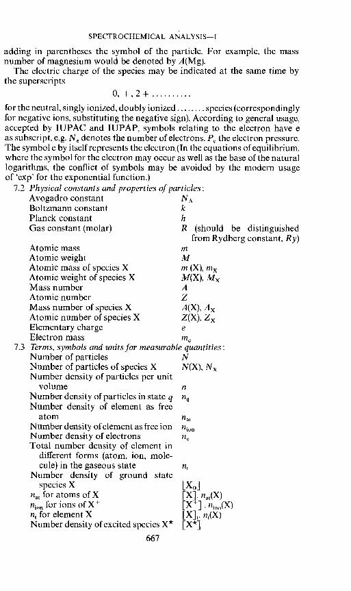
7.1 General rules—The intensities of spectral lines emitted by a sourcedepend on the fundamental properties of the atoms, molecules and otherparticles present, on their relative concentrations and on the physical condi-tions prevailing in the source. The system of terms and symbols must there-fore be able to provide a simple means of distinguishing these properties,concentrations or conditions, when and to whatever extent it is necessary to doso. To do this with simple means, terms and symbols are employed whichare already accepted by IUPAP or by IUPAC.
When, and only when, these symbols refer to different species of particlespresent at the same time, the correlation to the species may be given by
666
SPECTROCHEMICAL ANALYSIS—I
adding in parentheses the symbol of the particle. For example, the massnumber of magnesium would be denoted by A(Mg).
The electric charge of the species may be indicated at the same time bythe superscripts
0, +,2+for the neutral, singly ionized, doubly ionized species (correspondinglyfor negative ions, substituting the negative sign). According to general usage,accepted by IUPAC and IUPAP, symbols relating to the electron have eas subscript, e.g. Ne denotes the number of electrons, ethe electron pressure.The symbol e by itself represents the electron.(In the equations of equilibrium,where the symbol for the electron may occur as well as the base of the naturallogarithms, the conflict of symbols may be avoided by the modern usageof 'exp' for the exponential function.)
7.2 Physical constants and properties of particles:Avogadro constant NABoltzmann constant kPlanck constant hGas constant (molar) R (should be distinguished
from Rydberg constant, Ry)Atomic mass mAtomic weight MAtomic mass of species X m (X), mxAtomic weight of species X M(X), MMass number AAtomic number ZMass number of species X A(X), AAtomic number of species X Z(X), ZElementary charge eElectron mass me
7.3 Terms, symbols and units for measurable quantities:Number of particles NNumber of particles of species X N(X), NNumber density of particles per unit
volume nNumber density of particles in state q nqNumber density of element as free
atom atNumberdensity of element as free ion nNumber density of electrons neTotal number density of element in
different forms (atom, ion, mole-cule) in the gaseous state n
Number density of ground statespecies X [X0]
at for atoms of X [X], 1at(X)n10 for ions of X + [X], n10(X)n for element X [X], n(X)Number density of excited species X [X*]
667
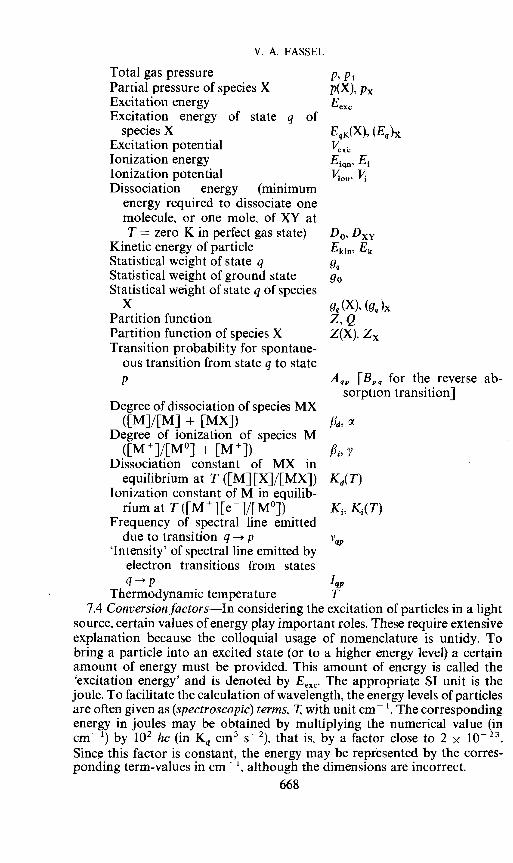
V. A. FASSEL
Total gas pressure p, PtPartial pressure of species X p(X), PxExcitation energy EexcExcitation energy of state q of
species X EqK(X), (Eq)xExcitation potentialIonization energy E1Ionization potential "rI, VDissociation energy (minimum
energy required to dissociate onemolecule, or one mole, of XY atT = zero K in perfect gas state) D0,
Kinetic energy of particle Ekjfl, EkStatistical weight of state q gqStatistical weight of ground state g0Statistical weight of state q of species
X gq (X), (gq)Partition function Z, QPartition function of species X Z(X), Z,Transition probability for spontane-
ous transition from state q to statep Aqp [Bpq for the reverse ab-
sorption transition]Degree of dissociation of species MX
([M]/[M] + [MX])Degree of ionization of species M
([M]/[M°] + [M]) f3, yDissociation constant of MX in
equilibrium at T ([M][X]/[MX]) Kd(T)Ionization constant of M in equilib-
rium at T([M][e]/[M°]) K1, K1(T)Frequency of spectral line emitted
due to transition q —+ p'Intensity' of spectral line emitted by
electron transitions from statesq—÷p 1qp
Thermodynamic temperature T7.4 Conversion factors—In considering the excitation of particles in a light
source, certain values of energy play important roles. These require extensiveexplanation because the colloquial usage of nomenclature is untidy. Tobring a particle into an excited state (or to a higher energy level) a certainamount of energy must be provided. This amount of energy is called the'excitation energy' and is denoted by Eexc. The appropriate SI unit is thejoule. To facilitate the calculation of wavelength, the energy levels of particlesare often given as (spectroscopic) terms, 7 with unit cm .Thecorrespondingenergy in joules may be obtained by multiplying the numerical value (incm 1) by 102 hc (in Kq cm3 s2), that is, by a factor close to 2 x 10- 23Since this factor is constant, the energy may be represented by the corres-ponding term-values in cm ', although the dimensions are incorrect.
668
SPECTROCHEMICAL ANALYSIS—I
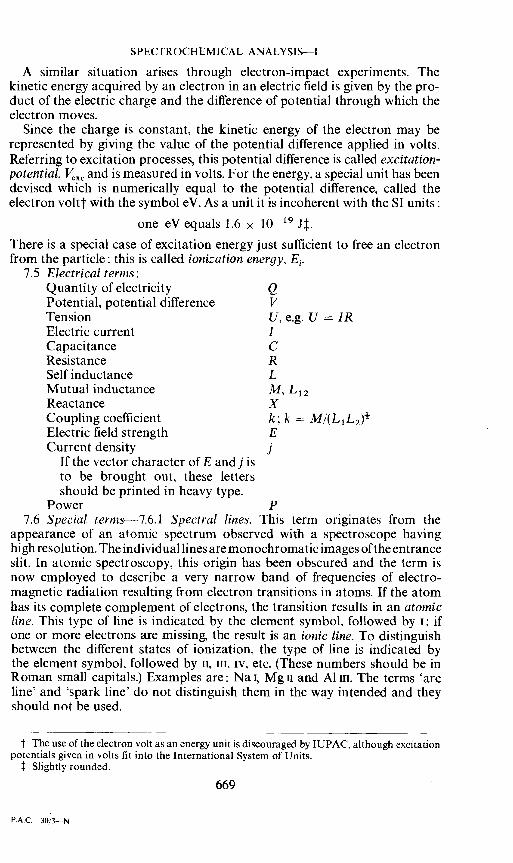
A similar situation arises through electron-impact experiments. Thekinetic energy acquired by an electron in an electric field is given by the pro-duct of the electric charge and the difference of potential through which theelectron moves.
Since the charge is constant, the kinetic energy of the electron may berepresented by giving the value of the potential difference applied in volts.Referring to excitation processes, this potential difference is called excitation-potential, l' and is measured in volts. For the energy, a special unit has beendevised which is numerically equal to the potential difference, called theelectron voltt with the symbol eV. As a unit it is incoherent with the SI units:
one eVequals 1.6 x 1O'9J.There is a special case of excitation energy just sufficient to free an electronfrom the particle: this is called ionization energy, E.
7.5 Electrical terms:Quantity of electricity QPotential, potential difference VTension U, e.g. U = JRElectric current ICapacitance CResistance RSelf inductance LMutual inductance M, L12Reactance XCoupling coefficient k; k = M/(L1L2)Electric field strength ECurrent density j
If the vector character of E and j isto be brought out, these lettersshould be printed in heavy type.
Power P7.6 Special ternis—7.6.1 Spectral lines. This term originates from the
appearance of an atomic spectrum observed with a spectroscope havinghigh resolution, The individual lines are monochromatic images of the entranceslit. In atomic spectroscopy, this origin has been obscured and the term isnow employed to describe a very narrow band of frequencies of electro-magnetic radiation resulting from electron transitions in atoms. If the atomhas its complete complement of electrons, the transition results in an atomicline. This type of line is indicated by the element symbol, followed by i; ifone or more electrons are missing, the result is an ionic line. To distinguishbetween the different states of ionization, the type of line is indicated bythe element symbol, followed by ii, iii, iv, etc. (These numbers should be inRoman small capitals.) Examples are: Na I, Mg u and Al iii. The terms 'arcline' and 'spark line' do not distinguish them in the way intended and theyshould not be used.
The use of the electron volt as an energy unit is discouraged by IUPAC, although excitationpotentials given in volts fit into the International System of Units.
Slightly rounded.
669
P.A.C3Q,3N
V. A. FASSEL
7.6.2 Selfabsorption occurs in emission sources of finite thickness whenradiant energy quanta emitted by atoms (or molecules) are absorbed byatoms of the same kind present in the same source. The absorbed energy isusually dissipated through collisional transfer of energy, or through emissionof radiant energy of the same or other frequencies. In consequence. the ob-served radiant intensity of a spectral line (or band component) emitted by asource may be less than the radiant intensity would be from an opticallythin source having the same number of emitting atoms. Self-absorption mayoccur in all emitting sources to some degree, whether they are homogeneousor not.
7.6.3 Self-reversal describes the effect of self-absorption on the shape ofthe spectral line emitted in light sources that are inhomogeneous in tempera-ture or excitation conditions in the direction of observation. Self-reversalis manifested as a decrease in intensity at the wavelength centre of the line.In extreme cases, the intensity at the wavelength centre may become so weakthat practically only the wings remain, giving the appearance of two fuzzylines.
7.6.4 Intensity versus time curve. In spectrochemical analysis the study ofthe variation of the intensity of a spectrum line with time is very important.When the aim is to study the volatilization and excitation of a sample forspectrochemical analysis, especially to choose the optimal exposure, theplot of intensity versus time is called the intensity time curve. The durationof such a study may be of the order of from tens of seconds to several minutes.The time range selected for the analytical exposure is the exposure time. Ifan initial portion of the excitation cycle is rejected before the analyticalexposure is made, these time intervals are designated as pre-arc or pre-sparkperiods, or other appropriate terms depending on the light source employed.Time-resolved spectroscopy refers to very short exposure periods. e.g.microseconds to milliseconds, employed when physical conditions in thelight source are studied.
7.7 ClassUlcation of additives—7.7.1 Additives are substances added tosamples for various purposes. There are many individual names for suchsubstances, which have arisen historically rather than systematically. Thefollowing scheme is an attempt to frame a system in such a way that the nameindicates the way the additive operates.
7.7.2 Spectrochemical buffers are added to samples and reference sampleswith the intention of making the measure of the analysis element less sensitiveto changes in concentration of an interferent.
7.7.3 A diluent is a substance added to a sample mainly to increase itsbulk for ease of handling. This addition may bring other benefits such as thesuppression of undesirable effects due to the previous composition of thematerial (see para. 6.1 matrix effects).
7.7.4 Material added to a sample to increase its volatilization, or that ofsome component of it, is a volatilizer, while, if it is done for the oppositereason, it is called a devolatilizer. Examples of volatilizers are: AIF3, orNaF, used with uranium, boron or silicon; also all chlorides. A typicaldevolatilizer is carbon, which gives rise to refractory carbides when used inthe analysis of tungsten or boron.
7.7.5 A spectrochemical carrier is an additive which gives rise to a gas670
SPECTROCHEMICAL ANALYSIS—I
which can help to transport the vapour of the sample material into the excita-tion region of the source, e.g. carbon in an air atmosphere when carbondioxide is formed.
VIII. PHOTOGRAPHIC INTENSITY MEASUREMENTS(PHOTOGRAPHIC PHOTOMETRY)
8.1 Introduction—Photographic intensity measurements play an importantpart in spectroscopy and spectrochemistry. This is due to the enormousinformation capacity of a photographic emulsion, which produces an imageof an extended spectrum in one exposure, showing not only the analysis lineunder consideration but many other features as well.
The type of such measurements, required in spectrochemical analysis. isrelatively simple: line intensities are to be compared within one spectrumonly (or a few of them) where the physical conditions are known and can bekept constant. This makes calibration easy and allows a straightforwardapproach, which will be outlined in this section.
8.2 Outline of the measuring procedure—8.2.1 The aim of photographicphotometry as used in spectrochemical analysis is the measurement of thecomparative intensities of spectrum lines. (Symbols: I and in the case oflogarithmic presentation Y = log 1.)
8.2.2 The physical quantity affecting the emulsion (plate, film) while it isexposed is the (radiant) exposure H. In general practice it is assumed thatH is proportional to the intensity I, so usually there is no need to determineH explicitly. This step is tacitly included in the procedure of calibrating anemulsion.
8.2.3 The exposure causes a separation of silver in the developed emul-sion. A measure of this effect is obtained by measuring the (photographic)transmittance 7; at the appropriate place on the plate. The optical instrumentused to measure the transmittance 7; is commonly called a micro photometer.This name is slightly inappropriate, but it is unambiguous and so widespreadthat it can be accepted. On the other hand, the expression 'densitometer'should not be used for such an instrument.
8.2.4 The transmittance 7; is an auxiliary and intermediate quantitywithout independent meaning. This is indicated by the subscript p. referringto photographic plate. The particular numerical value of 7; depends notonly on the exposure, the properties of the emulsion and the development,but also on the measuring arrangement [for example on the angular apertureof the light beam in the microphotometer]. There is no need to definegeneral standard conditions for measuring 7;. It is only necessary to keepthe measuring conditions constant within a series of measurements whichare to be compared or correlated with each other.
8.3 Mathematical treatment of measured values Jbr 7; (transJbrmations)—8.3.1 The exposure is generally related in a complicated way to the resultingphotographic transmittance 7;, which is measured, so making furthercalculation inconvenient. It is therefore advisable to transform 7; into amore tractable photographic parameter P. Ideally such a transformationshould give a linear relation between the parameter P and the logarithm ofthe exposure H (or instead, of the line intensity 1). But no mathematical
671

V. A. FASSEL
transformation—performed oniy for convenience—can ever improve poorphotometric measurements.
8.3.2 The relation between the logarithm of the intensity I and the photo-graphic parameter P is given by the emulsion calibration function or ingraphical presentation by the emulsion calibration curve.
8.3.3 If—by the selection of a suitable transformation from L to a parameterP— the resulting emulsion calibration curve is made straight, the equationof such a straight emulsion calibration curve is
P = y, log I/Iaor
P = y(Y— Y0)with Y= log IHere y, is the slope of the emulsion calibration curve and the index P canbe retained if it is clear for what parameter it holds.
I and '0 respectively correspond to the value of the exposure for whichP =0.
8.3.4 One special class of transformations L —*P leading to (nearly)straight emulsion calibration curves is produced by generalizing the Baker-Sampson—Seidel-transformation (see also 8.3.6).
P = iclog(1 —La)— log i;
By suitable choice of the transformation constant ic, this function is adaptableto many types of emulsions. The numerical values of the two logarithmicfunctions may be taken from tables or graphs. From this it can be seen thatthe calibration curve of a photographic emulsion can be characterized bythree numbers, e.g. K, yr,, Y0 (or ia), all dependent on wavelength. This mustessentially be true for all calibration curves having the same degree of straight-ness, although, by a special fixation of the transformation from L,, —P, oneof these constants may disappear from the equations, e.g. if yis made unity.
8.3.5 The establishment of a suitable transformation can be made bydifferent methods, for instance, by graphical methods resulting in a dis-tortion of the coordinate network or by combining mathematical functionswhich are known to lead to a linear relationship.
The selection of a suitable transformation is a practical and not a theoreticalmatter and is irrelevant for the intensity ratios to be determined—if theprocedure chosen is correctly performed. Therefore it is proposed to use thesymbol P for any photographic parameter leading to a (nearly) straight'emulsion calibration curve'. If necessary, the type of transformation maybe indicated in the context. Only when the relative merits of different trans-formations are discussed, different suitable symbols may be used (e.g. thehistoric ones from the literature or subscripts).
Unfortunately and most confusingly many different symbols have beenused for photographic parameters and for the respective transformations,giving a linearization of the emulsion calibration curve, e.g. S. D, P, TLL, 1, K, A etc., hence the proposal to use only the one symbol P.
8.3.6 Historical noteThe transformation that first served to linearize the emulsion calibration
curve, although not in the lower (low intensity) range, is the simple logarithmic
672

SPECTROCHEMICAL ANALYSIS—I
transformation which turns the transmittance L, into the blackening S. viz.S = — log T
In spite of the partial non-linearity just referred to, this parameter, blackeningS. is still widely used (Hurter and Driffield, H and D-curve). The transforma-tion obviously belongs to the class of transformations considered in 8.3.4,with the transformation constant K = 0. In English the blackening is oftenspoken of as the 'optical density' (D). But this may lead to misunderstanding,especially when 'optical' is omitted. In spectrochemical analysis, the use ofthe term 'optical density' is therefore discouraged, as well as that of the expres-sion 'H and D-curve', for the emulsion calibration curve.
The transformation that first helped to straighten the lower part of thecurve was used by two astronomers, Baker and Sampson, in 1924. It was
P = log (i/L1, — 1)= log(1 — L1,)— log 'This is the same equation as in 8.3.4 if K= 1. The same transformation wasrediscovered by Seidel in 1936 and subsequently was used extensively inspectrochemical analysis. Later various transformations have been proposedand investigated (see 8.3.5).
8.4 Practical calibration of a photographic emulsion—8.4.1 The practicalcalibration of a photographic emulsion is based on photometric measure-ments of photographic intensity marks (subscript m) produced by intensitiesof known ratios. The intensity marks are made with an intensity calibratingdevice, for example, a step filter with a known transmission ratiotm 'm, 1/'m, 2 Or one may resort to the use of a pair of spectrum lines ofwhich the intensity ratio is known under stipulated conditions.
8.4.2 The calibration procedure is simple if the intensity ratio of two spec-trum lines, close together in wavelength, is to be determined (quasi-mono-chromatic photometry) and if a photographic parameter P, yielding a linearemulsion calibration curve, is used. In this case all that need be measured isthe slope y,. Thevalues ofF1 and P2 for the two intensity marks are measured;then the slope of the emulsion calibration curve is
where= P1 P2
andAYm = log 'ml — log 'm2 = log Tm
8.4.3 Sometimes for convenience—especially with non-intermittent sources—a step sector is used as an intensity calibrating device. In this case the ex-posure H = Et is varied by variation oft and not by variation of the irradianceE as before. The measured values for ,&Pm in this case may differ markedlyfrom those obtained for the same ratio by variation of the irradiance E.
8.4.4 If the wavelengths )La and 4of the two spectrum lines to be compareddiffer so much that the emulsion calibration curves are different (hetero-chromatic photometry), then it may be necessary to use two different photo-
673
P.A.C.—30/3-—o
V. A. FASSEL
graphic parameters a and b produced by different transformation con-stants ic, in order to get the two emulsion calibration curves straight. Theslopes Ya and Yb of these two curves can be determined as before if the trans-mission ratios ; and 'rbof the intensity calibrating device for the two wave-lengths are known. In addition to this an intensity bridge from to 1b isnecessary in order to connect the two emulsion calibration curves and soafford the calculation of the difference in response Ya, — of the emulsionat the two wavelengths. An intensity bridge ratio
log 'JIb = M'a,bcan be derived from a spectrum with known spectral distribution of intensi-ties. Examples are: the spectrum of a standard d.c. graphite arc or of atungsten ribbon lamp etc. This idea of an intensity bridge is usually implicitin the term 'external standard'. But the use of this term is discouraged sinceit is not clearly defined and might wrongly be considered as the oppositeof 'internal standard', a term that in the future should be replaced by referenceelement or reference intensity.
APPENDIX AGeneral Principles of Nomenclature Standardization
The following article is part of a report of the Joint Committee on Nomen-clature in Applied Spectroscopy. It is reprinted here by permission of ASTMfrom Methods for Emission Spectrochemical Analysis, pp 84—86 (1957)published by the American Society for Testing Materials, 1916 Race St.,Philadelphia, Pa. (This article has not been reprinted in recent editions ofthe book.)
The footnotes have been added by this Commission (V.4).1. Manuscript. In preparing manuscripts and talks, careful attention should
be given to the use of nomenclature from this and other standard lists and tothe principles here given. Controversial or unusual terms should be definedclearly. When other terms are not defined, it is desirable to make referenceto the standard lists from which they are taken.
2. Units. The same term and the same symbol should be used for a givenquantity, regardless of the units employed and regardless of special valuesoccurring for different states, molecules, times etc. Special values may bedistinguished when necessary by subscripts or superscripts. The units usedshould always be stated carefully and explicitly
3. Multiple meanings. A given term should not have more than one technicalmeaning in any branch of physical science. For instance, if 'density' is acceptedas the term for mass divided by volume, it should not be employed as ashortened form of optical density.
4. Multiple terms. A given technical concept should not have more thanone name. For example, 'analytical curve' and 'working curve' should notboth be standard terms.
5. Related concepts. If two or more concepts are closely related, this factshould be reflected in the similarity of the names assigned to them. Instru-ments should be named for the quantities they measure.
(a) One obvious way is to incorporate the name of the most basic of the674

SPECTROCHEMICAL ANALYSIS—I
several concepts in the names of those subsidiary to it. Thus, in speaking ofvarious standards, one should use, for example, internal standardt, primarystandard, etc.
(b) Another exceptionally useful way to indicate such relations is toutilize the conventions regarding suffixes that are now fairly well established,especially in electricity. There are at least nine such suffixes:-or, meaning a device. For example, comparator, reflector, generator and
capacitor. (Other suffixes used to denote devices are -er, as in amplifier,and -ment, as in filament.)
-ation, meaning a process or result of a process. For example, calibration,excitation, ionization and radiation (-ing, as in lighting, is also used todenote a process.)
-ance, meaning a property of a device or body. For example resistance,capacitance, transmittance and absorbance.
-ity, meaning a property of a substance. For example, absorptivity, density,solubility, resistivity (which is simpler than the older term, specificresistance), conductivity, and so on.
-meter, meaning a measuring device. For example, ammeter, spectrometerand densitometer.
-scope, meaning an optical or viewing device, as in electroscope, microscopeand spectroscope.
-graph, meaning a device to produce a record of observations as in telegraphand spectrograph.
-gram, meaning the record produced by an instrument as in telegram andspectrogram.
-scopy, meaning observation, as in spectroscopy.6. Contrasting concepts. The names for two diametrically opposite ideas
should differ markedly in appearance and sound; for example §,microscopicand macroscopic—each consists of eleven letters, with only one of themdifferent, and their pronunciation may lead to confusion.
7. Selfexplanatory terms. A term should, when possible, be more or lessself-explanatory and thus easy to learn and to associate with its concepts.Some terms that appear to satisfy this requirement are: buffer, carrier andemulsion calibration curve. On the other hand, electromotive force and theold term electric capacity not only fail to explain, but actually foster mis-conceptions.
8. Simplicity. The chosen term should be simple and euphonious, and itshould have the simplest spelling that is sanctioned by dictionaries. Examplesof acceptable simpler spellings are: aline, distil, focused, gage, sulfur. Termssuch as quantity of heat and quantity of charge not only lack simplicitybut are redundant, the quantity not being needed. Sinusoidalfunction shouldgive way to sinoidal function and 'coefficient of linear expansion' to 'linearexpansivity', which is not only simpler but utilizes the -ity convention.
t 'internal standard' to be replaced by 'internal reference' see § 6.2.2 and 6.3.1.The term 'specific' has now been restricted to the meaning 'divided by mass'.
§ Another unfortunate choice in our own field is radiance and irradiance (see para. 4.1).See para. 7.7.5 of this document, where 'carrier' is defined in a narrower meaning than
formerly.
675
V. A. FASSEL
9. Internationality. The name for a particular concept preferably shouldhave essentially the same form in a number of the chief languages of theworld. This is already true of various technical terms in common use as, forinstance, energy, entropy and many terms having certain of the suffixespreviously discussed. For the four suffixes, -or, -ation, -ance, -ity, a tabulationof 544 entries from eight different languages shows that one or the other ofthese suffixes is used in 96 per cent of the total. When the tabulation is con-fined to five of these eight languages——namely English, French, Italian,Spanish and Portuguese—there is agreement in 347 out of 355 cases, 98 percent. Thus the proposal to achieve some degree of internationality in termino-logy is by no means impracticable.
10. Faulty terms. If a term is slightly faulty, but is too firmly established tobe discarded, a brief explanatory comment should be included with itsdefinition. If a term is faulty in some important respect, an effort should bemade to change it, no matter how well established it may be. There is nobetter example of such a term than electromotive force.
11. New terms. The question arises as to the procedure to be followed inchoosing a brand new term, either to replace a faulty one or to designate anew idea as yet unnamed. Obviously there are several alternative methods:
(a) Borrow a word from ordinary language. The resulting term could beambiguous, because of inability to decide from the context in a particularcase whether the technical or the everyday meaning is intended; moreoversuch a term will not be international, since it generally cannot be taken overdirectly into other languages. On the other hand, many existing termsborrowed from ordinary language have proved to be quite satisfactory. Thegeneral agreement is, however, that this method of obtaining a new termshould be used with considerable restraint.
(b) Borrow a word from a living, foreign language. Gibbs did this when hetook the French word 'ensemble' and gave it a new technical meaning. Oneobjection to this general method is that the borrowed term, while good forus, may not be too satisfactory for the country from which we borrowed it.For instance, 'ensemble' in French does not convey Gibbs's idea very well.
(c) Coin a word by making an arbitrary although euphonious combinationof a number of the letters of the alphabet. This method might serve onoccasions, but the resulting term could be hard to learn.
(d) Adopt the name of the discoverer of the idea. If this somewhat lazyway of naming a concept is resorted to, one should at least make sure thatthe name selected is that of the real discoverer as established by priority ofpublication.
(e) Construct the new term from parts taken from a classical language,such as Greekt or Latin. The word, being a new one, is immediately recog-nizable as a technical term. If the component parts are properly chosen, itwill also be more or less self-explanatory. Some think classical Greek is thebest language for this purpose.
(0 Do not use a registered trade name of a particular company for a classof instruments.
t For Greek words Latin transliteration has been recommended, to avoid ambiguity ofspelling.
676

SPECTROCHEMICAL ANALYSIS—I
APPENDIX BApplication of the Concept of Optical Conductance
B.1. General definition—Optical conductance G is defined by the basicequation
= BGr
or in words: Flux = Radiance x Optical conductance x Transmissionfactor, where G embraces the geometric factors. B and cli are appropriatelyspecified.
B.2.1 Passage of flux between elements of area of source and sink (e.g. areceiver). dS1 is an element of area of the source and dS2 of the sink, a12 isthe intervening distance, and the normal to dS1 makes the angle withthe direction from source to sink, and a2 applies similarly to dS2. Then,with dS1 and dS2
dcli = B(a1) cos a1 dS1 cos a2 dS2/a2= B(oc1)dG12
B.2.2 Integration. If in the above dS1 is an element of an area S1. and dS2of S2. the total flux from S1 to S2 is
=$s, js2 B(x,y,z ) cos a1. cos a2 dS1 dS2/a2
If the radiance may be taken as constant over the whole surface S1. or if itmay be replaced adequately by an average value, the radiance may be takenoutside the integral, which then constitutes G.
B.3 Generalization to allow for refractive index—If the medium betweenS1 and S2 has the refractive index n, the optical conductance G is defined by
G =B.4 The practical importance of the concept of optical conductance will
be realized, if one remembers that the radiance, observed within all subse-quent apertures of an optical arrangement is invariant—except for lossesby reflection, absorption or scattering (which are taken into account by thetransmission factor r).
Therefore, in a correctly designed optical arrangement, consisting of asequence of parts or instruments (e.g. source—absorption cell—monochrom-ator—receiver), the invariance of the calculated optical conductance betweenany two apertures in sequence also presupposes that all apertures are fullyilluminated. (Of course, some apertures may be larger than necessary; inthese cases, only the part filled with radiation must be considered.)
In consequence, the optical conductance of some part in the arrangementthat cannot be enlarged for practical or technical reasons determines theeffective optical conductance of all other parts and of the whole arrangement.[For example, such a limit for the effective optical conductance may beimposed by the dimensions of an absorption cell (see formula B.5.1) orthose of a monochromator (B.5.6), a photometer device, or of an interferencefilter (B.5.2).] This fact greatly simplifies basic decisions, the choice of partsor instruments and rough calculations of the available flux.
677
V. A. FASSEL
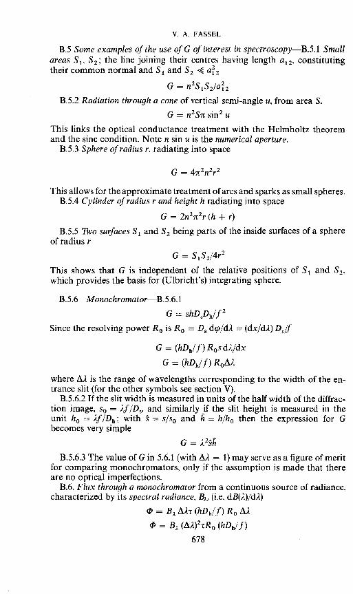
B.5 Some examples of the use of G of interest in spectroscopy—B.5.1 Smallareas S1. S; the line joining their centres having length a12, constitutingtheir common normal and S1 and S2 a2
G = n2S1S2/a2
B.5.2 Radiation through a cone of vertical semi-angle u, from area S.
G = n2Sir sin2 u
This links the optical conductance treatment with the Helmholtz theoremand the sine condition. Note n sin u is the numerical aperture.
B.5.3 Sphere of radius r, radiating into space
G = 4ir2n2r2
This allows for the approximate treatment of arcs and sparks as small spheres.B.5.4 Cylinder of radius r and height h radiating into space
G = 2n2it2r (h + r)B.5.5 Two surfaces S1 and S2 being parts of the inside surfaces of a sphere
of radius rG = S1S2/4r2
This shows that G is independent of the relative positions of S1 and S2.which provides the basis for (Ulbricht's) integrating sphere.
B.5.6 Monochromator—B.5.6.l
G shDSDh/f2Since the resolving power R0 is R0 = D d(p/d). = (dx/d2) D/f
G = (hDh/f) RØsd)L/dx
G = (hDh/f) R0A2
where A). is the range of wavelengths corresponding to the width of the en-trance slit (for the other symbols see section V).
B.5.6.2 If the slit width is measured in units of the half width of the diffrac-tion image, s0 = ).f/D, and similarly if the slit height is measured in theunit h0 = ).f/Dh; with = s/s0 and h = h/h0 then the expression for Gbecomes very simple
G =B.5.6.3 The value of G in 5.6.1 (with A). = 1) may serve as a figure of merit
for comparing monochromators, only if the assumption is made that thereare no optical imperfections.
B.6. Flux through a monochromator from a continuous source of radiance,characterized by its spectral radiance, B, (i.e. dB1)/d2)
= B2 AAr (hDh/f) R0 A).= B2 (AA)2rR0 (hDh/f)
678
SPECTROCI-IEMICAL ANALYSIS—I
Therefore, the square of the bandwidth is important. The monochromatoritself is characterized in this equation by the product
ZM = tR0 (hDh/f)which obviously is a figure of merit for the transport of energy. This equationmay also be written (from 5.6.1) as
ZM
which is the optical conductance per unit bandwidth.
679