noise control of an underground continuous miner, … control of an underground continuous miner,...
TRANSCRIPT

Informational Report 1056
Noise Controlof an UndergroundContinuous Miner,Auger-Type
By Dennis A. Giardino, Thomas G. Bobick, and Leonard C. Marraccini
Technical Support Center, Pittsburgh, Pa.
UNITED STATES DEPARTMENT OF THE INTERIORCecil D. Andrus, Secretary
Mining Enforcement and Safety AdministrationRobert E. Barrett, Administrator

CONTENTS
Abstract ............ ...................................................Introduction ...........................................................Acknowledgment .........................................................Machine description ....................................................Instrumentation ........................................................Procedure ..............................................................Materials and costs ....................................................Identification and treatment of Mark 20 noise sources ..................Results --surface .......................................................Results--underground ...................................................Discussion of results ..................................................Appendix A. --One-third octave band noise measurements at various
locations around the miner, unloaded, before and after noise controlmodifications (9 positions) ..........................................
Appendix B. --One-third octave band vibration measurements at variouslocations on the miner, unloaded, before and after noise controlmodifications (9 positions) ..........................................
Appendix C. --One-third octave band noise measurements at variouslocations around the bridge conveyor, unloaded, before and afternoise control modifications (11 positions) ..........................
Appendix D. --One-Third octave band vibration measurements at variouslocations on the bridge conveyor, unloaded, before and after noisecontrol modifications (10 positions) .................................
1.2.
3.4.
5A.
5B.
6.7.
8.
9.10.
11.
12.
13.
Mark 20 auger miner and bridge conveyor ...........................Instrumentation systems used to measure sound, vibration and
reverberation times .............................................Microphone boom system used in sound power measurements ...........The four basic noise producing systems for the Wilcox miner .......Unmodified cutting heads (without bits) for the Wilcox Mark 20
miner ...........................................................Cutting heads (without bits) for the Wilcox Mark 20 miner,modified with metal supports ....................................
Summary of noise control procedure used to quiet conveyor pans ....Diagram showing the installation of damping strips to a section
of the bridge conveyor ..........................................Configuration of center damping strip at the rear end of the bridge
and miner conveyors ............................. ................Installing damping strips on the miner conveyor ...................Diagram showing construction details of extended lower wear
strips on the miner .............................................Back-end view of bridge conveyor showing the lower extended wear
strip ...........................................................Noise control modifications made to the front of the bridge
conveyor ........................................................Diagram showing the noise control modifications made to the front
of the bridge conveyor ..........................................
ILLUSTRATIONS
11224468
324245
47
50
53
55
3
468
10
1112
13
1415
16
17
18
19
ii
ILLUSTRATIONS--ContinuedPage
14.
15.
16.
17.
18.
19.20.21.22.23.
24.
25.
26.27.
28.
29.
30.
31.
32.
33.
34 ;
35.
36.
Diagram showing noise control modifications made to the frontof the miner .................................................
Close-up view showing noise control modifications made to thefront of the miner . . . . . . . . . . . . . . . . . . . . . . . . . . . . . . . . . . . . ........
Summary of the noise control procedure used on the conveyordrive assemblies . . . . . . . . . . . . . . . . . . . . . . . . . . . . . . . . . . . . . . . . . . . . . . .
Diagram illustrating the noise control modifications made tothe conveyor drive assemblies ...............................
Diagram illustrating sources and paths of cooling system noiseand the subsequent noise control treatment . . . . . . . . . . . . . . . . . . . . .
Summary of the construction of the operator's barrier panel......Diagram showing details of operator barrier panel................Diagram showing construction details of the internal barrier.....Placement of the internal barrier for the left side of the miner.Diagram illustrating one treatment technique used on cover panels
of miner . . . . . . . . . . . . . . . . . . . . . . . . . . . . . . . . . . . . . . . . . . . . . . . . . . . . . . .Summary of alternate treatment used on cover panels of miner
and bridge conveyors . . . . . . . . . . . . . . . . . . . . . . . . . . . . . . . . . . . . . . . . . . .Summary of techniques used in mounting cover panels on miner
and bridge conveyor ...........................................Noise controlled Wilcox Mark 20 auger miner and bridge conveyor..A-weighted noise levels around miner, before and after
modifications . . . . . . . . . . . . . . . . . . . . . . . . . . . . . . . . . . . . . . . . . . . . . . . . . .C-weighted noise levels around miner, before and aftermodifications . . . . . . . . . . . . . . . . . . . . . . . . . . . . . . . . . . . . . . . . . . . . . . . . . .
Octave band spectra of noise at each of three worker positions,before and after modifications . . . . . . . . . . . . . . . . . . . . . . . . . . . . . . . . .
Vibration levels (re 30 µg) at several positions on the miner,before and after modifications.......... . . . . . . . . . . . . . . . . . . . . . . .
A-weighted noise levels and octave band spectra around bridgeconveyor, before and after modifications . . . . . . . . . . . . . . . . . . . . . . .
C-weighted noise levels and octave band spectra around bridgeconveyor, before and after modifications . . . . . . . . . . . . . . . . . . . . . . .
Vibration levels (re 30 µg) at several positions on bridgeconveyor, before and after modifications . . . . . . . . . . . . . . . . . . . . . . .
Total sound power of miner (re 10-12 watts) in octave bands,before and after modifications . . . . . . . . . . . . . . . . . . . . . . . . . . . . . . . . .
Underground noise measurement positions around miner andbridge conveyor . . . . . . . . . . . . . . . . . . . . . . . . . . . . . . . . . . . . . . . . . . . . . . . .
One-third octave band analysis of noise measured atoperator's position, before and after noise controlmodifications . . . . . . . . . . . . . . . . . . . . . . . . . . . . . . . . . . . . . . . . . . . . . . . . . .
20
21
22
23
2425262727
28
29
3031
33
33
36
36
37
38
40
41
42
43

iii
TABLES
1.2.
3.
4.
5.
6.
7.
8.9.
Noise control materials used during the modification program......Noise levels (RTA output) around miner before and after
modifications-- everything on miner in operation; no bridgeconveyor. . . . . . . . . . . . . . . . . . . . . . . . . . .............................
Acceleration measurements on miner before and aftermodifications-- everything on miner in operation; no bridgeconveyor . . . . . . . . . . . . . . . . . . . . . . . . . . . . . . . . . . . . . . . . . . . . . . . . . . . . . . . .
Noise levels (RTA output) around bridge conveyor before andafter modifications--everything on both miner and bridgeconveyor in operation . . . . . . . . . . . . . . . . . . . . . . . . . . . . . . . . . . . . . . . . . . .
Acceleration measurements on bridge conveyor before and aftermodifications-- everything on both miner and bridgeconveyor in operation . . . . . . . . . . . . . . . . . . . . . . . . . . . . . . . . . . . . . . . . . . .
Sound power levels measured before and after acousticalmodification of Wilcox miner . . . . . . . . . . . . . . . . . . . . . . . . . . . . . . . . . . . .
Noise level of unmodified and modified miner and bridgeconveyor, cutting coal . . . . . . . . . . . . . . . . . . . . . . . . . . . . . . . . . . . . . . . . . .
Noise contours around miner, unloaded condition....,..............Noise contours around bridge conveyor, unloaded condition.........
Page
7
34
35
39
39
41
434444

NOISE CONTROL OF AN UNDERGROUND CONTINUOUS MINER,AUGER-TYPE
Dennis A. Giordino,1 Thomas G. Bobick,2 and Leonard C. Marraccini3
ABSTRACT
This report describes the noise control modifications made on a WilcoxMark 204 underground auger miner and related bridge conveyor. Sufficientdetail is given so that interested parties can use the report as a manual forconducting similar modifications. The reported reduction in operator noiselevel is 10 dBA as measured unloaded at the MESA test facility. Undergroundnoise surveys conducted over a l-year interval showed the noise level at theoperator's position to be 97 dBA, a reduction of 5 dBA from the before modi-fication noise level of 102 dBA. An extensive diagnosis of the machine noisesources is also given along with comprehensive acoustical data includingl/3 octave band spectra of noise, vibration and sound power.
INTRODUCTION
Recent findings have shown that next to the underground stoping drill,6the equipment which has the second greatest number of violations is the under-ground auger miner. Numerous surveys which have been conducted on this equip-ment have verified that the total noise exposure of the operator and helperscan be quite excessive. A typical survey was the one conducted at the No. 19Mine of Buchanan & Sons Coal Company, Wise,Va., during October 1974. Dataobtained from a Wilcox Mark 20 auger miner showed an average noise levelof 102dBA for the operator and 103-104 dBA for the jacksetters. The average oper-ating time was approximately 3-l/4 hours (ranging from 2-l/2 to 4 hours).Using this data, an average noise exposure index of 2.15 (ranging from 1.65 to2.64) is computed for the operator and 2.64 (ranging from 2.03 to 3.25) forthe jacksetters.
1Chief, Noise Branch.2Mining engineer, Noise Branch.3Physicist, Noise Branch.4Reference to specific brands, equipment or trade names in this report is made
to facilitate understanding and does not imply endorsement by the MiningEnforcement and Safety Administration.
5"The Noise Environment of the Underground Coal Mine" by T. G. Bobick and D. A.Giardino, MESA Informational Report No. 1034.

2
Besides verifying that the noise exposure of the workers exceeded theFederal noise regulations, the field survey identified several noise sourceson the miner and accompanying bridge conveyor which contributed to the highnoise levels. The major source was the chain conveyor which transported themined coal from the face. Another source was the noise generated by the augerheads as they cut coal. Even though the major noise sources were identified,very little noise control work could be done underground because of inconven-ient working conditions.
After months of planning and negotiating, a cooperative agreement wasentered into with Buchanan & Sons Coal Company, mine owner; Fairchild, Inc.,machine manufacturer; and MESA, to noise control the machine. The terms ofthe agreement were that the owner supplied the auger miner, The manufacturertransported the equipment and provided a mechanic to the Pittsburgh TechnicalSupport Center. After the arrival of the equipment, it was the responsibilityof the Noise Branch to provide modifications for quieting the system.
ACKNOWLEDGMENT
The authors wish to express their appreciation to Buchanan & Sons CoalCompany, Fairchild, Inc., and Mr. Gilmur Hughes, mechanic, Fairchild, Inc.,whose cooperation and suggestions contributed to the success of the project.
The authors also wish to acknowledge members of the Noise Branch fortheir participation in this project which involved countless hours of workbeyond the normal duties. AS a result of their work on this project, thefollowing individuals received a Special Achievement Award from MESA forperformance above and beyond their normal duties. They are:
Jerry W. Ante1Felix J. Della ValleCornelis A. DirkmaatGeorge DurktJohn H. PerryJohn P. SeilerAnthony J. StrazisarJames A. VoelkerRoland Tyler
MACHINE DESCRIPTION
The Mark 20 auger miner and related bridge conveyor, shown in figure 1,are manufactured by the Wilcox Division of Fairchild, Inc., Beckley, W. Va.The Mark 20 is a controlled arc miner designed for mining coal from seamheights of 26 to 50 inches. The overall length of the Mark 20 is 24 feet;the width is approximately 8 feet. The overall height with the augers loweredis 24 inches and the maximum height is 48 inches when the augers are fullyelevated. The weight of the machine is approximately 12 tons.
Dual rotating augers, which can be individually raised or lowered accord-ing to seam thickness, are used to extract the coal. Each of the augers is

3
powered by a 100-hp, 440-volt, dc motor. The coal is extracted as the mineradvances in a sweeping pattern across the face. This sweeping movement isachieved by the use of two anchor jacks, one located on the right and theother on the left side of the miner. The machine sweeps to the right as it ispulled in that direction by the right front winch that winds cable attached tothe right anchor jack. The opposite jack system is then used in moving theminer to the left. The 100-hp drive motors, besides operating the gear chaindrives which turn the cutting auger heads, also power the hydraulic pumps.These pumps supply the hydraulic power for the control system of the machine.
Once the coal is cut, it is gathered by means of rotating screws onto theconveyor pan of the miner. The coal is moved the length of the machine via achain conveyor and dumped onto a bridge conveyor system which removes it fromthe face area, Both the machine and bridge conveyors are powered by individ-ual 15-hp, 440-volt, 3-phase, ac motors. The conveyor motors are mechanicallylinked to a sprocket assembly which operates the chain conveyors on the minerand bridge conveyor.
The-bridge conveyor unit is a continuous haulage system for removing thecoal from the working area quickly and efficiently, The bridge attachesdirectly to the rear dumping point of the Mark 20, thus enabling it to followeach move of the miner uninterrupted. The coal is moved by the bridge to asecond dumping point approximately 34 feet away where it begins the journey tothe surface. The bridge conveyor receives its ac power through a directelectrical hookup with the miner control panel.
Right jack setter
Operator positionI
FIGURE 1. - Mark 20 auger miner and bridge conveyor.

4
A
FIGURE 2. - Instrumentation systems used to measure sound, vibration and reverberation times.
INSTRUMENTATION
Various types of instrumentation systems were utilized to measure thenoise, vibration and reverberation during this noise control project.Figure 2 gives a block diagram of the systems used. The instruments met allthe various ANSI Standards for Type I or II systems. The manufacturers namesare shown for compatibility of the components, not as an endorsement of theproducts by MESA. Other instruments could have been used in place of thosementioned.
PROCEDURE
The Wilcox auger miner was placed on two 4"X4" wooden beams on the con-crete floor of a large, garage-type building at the Pittsburgh TechnicalSupport facilities. In an attempt to characterize the acoustical environmentin which sound measurements were to be taken, reverberation times were mea-sured inside the building where the Wilcox auger miner was located. This wasdone, prior to any noise measurements, in order to relate the surface experi-mental data to actual underground noise levels.6 Using an impulse noise
6"Predicting Noise Levels From Sound Power Data" by L. C. Marraccini and D.A.Giardino, published in Sound and vibration Magazine,Novemberl974,pp. 28-30.
5
source, decay curves were obtained using the system described in figure 2B.These decay curves were then used to calculate reverberation times in octaveband center frequencies of 125, 250, 500, 1,000, 2,000, 4,000 and 8,000 Hz, aswell as the total A- and C-weightings.
After the reverberation measurements were completed, a comprehensivesurvey of noise, vibration and sound power levels were conducted to obtainbaseline data. Sound and vibration measurements were taken both with and with-out the associated bridge conveyor attached to the miner. In order to accu-rately compare the before and after modification data, sound measurements weretaken at fixed locations around the miner and bridge conveyor. The microphonewas oriented in a vertical, upward direction approximately 30" above the floorand 2' from the test item. Vibration measurements were also taken at standard-ized locations on both the miner and bridge conveyor.
Sound measurements were taken utilizing the instrumentation system shownin figure 24. The system was acoustically calibrated using a General RadioType 1567 sound level calibrator. The microphone was tripod-mounted and posi-tioned so it would be 30" above the floor at each monitoring location. Soundpressure levels were monitored sequentially at each fixed location by the realtime analyzer. The sound pressure levels were printed out in l/3 and fulloctave frequency bands by means of a teletypewriter which was attached to theoutput of the real time analyzer. A- and C-weighted noise levels were alsomeasured with a General Radio Type 1565-B sound level meter at the samelocation.
The vibration monitoring system is shown in figure 2s. The system wascalibrated using a General Radio vibration calibrator Type 1557-A. Theaccelerometer was mounted to the measuring location by use of a permanentmagnet. Vibration was monitored at each premarked location by means of thereal time analyzer. Vibration data was given in decibels (re 30 µg and fre-quency analyzed into l/3 and full octave bands.
The total sound power output of the Wilcox miner was measured using astandard hemispherical technique.7 With all systems on the miner in operation,the acoustical center was first determined. This was then used as the centerpoint about which an imaginary hemisphere was constructed around the machine.The radius of the hemisphere was selected to be 15' based on the geometry ofthe building housing the miner. Sound pressure level readings were taken atthe center of 12 predetermined equilateral triangles defining the surface ofthis imaginary hemisphere. A B&K Type 4145 microphone, calibrated using aB&K Type 4230 calibrator, was positioned at the center of each equilateraltriangle. This was accomplished (fig. 3) by utilizing an Atlas Model BS-37microphone boom. The acoustical signal from the microphone was sent through aB&K Type 2619 preamplifier into a B&K Type 2113 audio frequency spectrometer.Sound pressure levels were plotted at octave band center frequencies (31.5 to
7Harris, C. M. (ed.). Handbook of Noise Control, McGraw-Hill Book Company,1957, pp. 17.30-17.32.

FIGURE 3. - Microphone boom system used in sound power measurements.
8 kHz) by means of a B&K Type 2305 level recorder. These results were thenused to calculate sound power levels.
Upon completion of all noise control modifications, a survey of noise,vibrationand sound power levels was again conducted. All of these measure-ments were made at the same locations and using the same instrumentation asused in the premodification survey.
MATERIALS AND COSTS
In noise controlling the Wilcox Mark 20 mining system, several differenttypes of materials were needed. These included vibrational damping materials,acoustically absorptive materials, adhesives, steel wear strips and assortednuts and bolts. A complete breakdown in terms of use, quantities, manufac-turers and costs is given in table 1. The total cost for materials was about$2,400. It should be noted that since this was a prototype project, largerquantities of materials were ordered than actually used. Other workersattempting this project, with the directions supplied in this report, wouldprobably use significantly less material than specified in table 1. Thiswould result in less cost than the quoted $2,400.
Labor costs, for the noise control procedure, were estimated to be about$3,000 corresponding to 30 mandays at $l00* per manday. Again, more mechani-cally skilled workers (attempting the procedure with beforehand information)could probably finish the noise control project in less than 30 mandays. Thiswould result in a further savings in cost.
8Beranek, L. L. (ed.). Noise and Vibration Control, McGraw-Hill Book Company,1971, pp. 149-155.
*These were the prevailing rates as of July-August 1975.

Material type
Dense, vibrationabsorbing rubber
TABLE 1. - Noise control materials used during the modification program
Dense, vibrationabsorbing rub-ber, good trans-mission loss
Light-weight,sound absorbingfiberglass
Combinationsound barriermaterial andsound absorbingfoam
Viscous liquidwhich dries intoa vibrationabsorbing rubber
Epoxy adhesive
Hardened steelwear strips
Metal studs
Cover buttons
Stud weldinggun
Steel plate/sheet metal
Assorted nuts,bolts andscrews
Material Cost =Labor Costs,30 days at
USC Quantity Brand name and manufacturer*
Vibration dampingand/or isolation
3 sheets--each4' x 4' x 3/16"
E-A-R C-2003, E-A-R Corp.376 University Ave., Westwood, MA02090
Approx.cost
$420
Vibration dampingand/o+ acous-tical barrier
3 sheets--each4' x 4' x l/4"
E-A-R- C-1002. E-A-R Corp.376 University Ave., Westwood, MA02090
675
Absorption of air-borne noise
4' x 35' x 1" Insul-Quilt AGC, Insul-Caustic/Birma Corp., Jernee Mill Road,Sayreville, NJ 08872
200
Acoustical barrierand soundabsorption
4' x 20' x l/2" Durasonic No. 5155, Duracote Corp.,350 N. Diamond St.,Ravenna, OH 44266
100
Vibration dampingof hollow or hardto reachstructure
10 lb Flexane 80, Liquid Urethane,Devcon Corporation,Danvers, MA 01923
100
To firmly glueacousticalmaterial tometal parts
3 gal Bostik No. 7132, Two-part vinyllaminating adhesive, USM Corp.,Bostik Division, Middleton, MA01949
70
TO provide longwearing surfaceson acousticalmaterial whereneeded
18 pieces--each3' x 20' x 1/4
Jalloy Material, Jones & LaughlinSteel Corp., Etna, PA 15223
750
Co permit installa-tion of acousticalmaterials insidecover panels
150 l/4" diam,3" length
Barrier Corp., Tigard IndustrialPark, 9908 S. W. Tigard St.,Tigard, OR 97223
12
To secure thematerials to themetal studs
150 Barrier Corp., Tigard IndustrialPark, 9908 S. W. Tigard St.,Tigard, OR 97223
Co install themetal studs onthe inside of thecover panels
Barrier Corp. (Supplied toNoise Branch, no charge)
30
Rental$l00/wk.$300/mo.
Used in conjunctionwith acousticalmaterial to formbarrier
3' x 3' x 1/4"5 ft square,18 gage
Not applicable, Local source 50
For attachingwear strips,barriers, etc.
$2,457 *These matr
Not applicable, local source 50
ials are listed pecifically for identification purposes andshould not be construed as an endorsement of these products by MESA. Othermaterials which could be used as substitutes are available commercially.
7
$l00/day = 3,000 However, regulations concerning the flammability requirements of materialsused underground will be promulgated in the near future. Before using any
Total Cost = 5,457 materials underground, they must pass the requirements for flameretardation.

8
From the above discussion, it can be seen that the total cost for thisprototype noise control project was $5,400 (approximately 4 percent of thecost of a new miner-bridge conveyor system). It is estimated that if thesame noise control program was conducted on another Wilcox miner, the jobcould be completed for substantially less, p robably in the neighborhood of$3,500.
IDENTIFICATION AND TREATMENT OF MARK 20 NOISE SOURCES
In order to noise control the Wilcox auger miner, it is first necessaryto determine specific sources of noise and their relative contribution to thenoise levels as experienced by the workers (that is, operator, right and leftjacksetters). An investigation of possible noise sources was undertaken byanalyzing the miner on a systems basis. The noise contribution of each com-ponent in the system was determined by careful acoustic measurements. Thefour systems considered in this analysis, listed in order of their noise emis-sion levels, are as follows: (1) cutting heads (augers), (2) conveyor system,(3) cutting head drive assembly, and (4) winch system. Figure 4 illustrates the relative position of these systems for the Wilcox auger miner and bridgeconveyor.
The following section gives a description of the noise sources and gener-ating mechanisms for each system, along with the acoustical modificationswhich can be made for noise control purposes.
1. Cutting Heads
The coal cutting heads for the Wilcox Mark 20 are shown in figure 5A.Each of the two cutting heads, when mounted on the miner, are powered by a100-hp 440-volt, dc motor and drive train. In operation, they rotate in
KEY
FIGURE 4. - The four basic noise producing systems for the Wilcox miner.

9
opposite directions to each other. Incorporated in the core of the cuttingheads are nozzles, from which water is sprayed onto the face to reduce dust.
The noise generated by the cutting head system is the predominate noisewhen the machine is mining coal. It especially affects the jacksetters whoare located toward the front of the miner. There are several mechanisms whichgenerate noise during the cutting operation. They are:
a. Cutting Bit-Coal Interaction
This noise is the result of individual bits on each cutting headimpacting into the coal. It occurs not only in the auger miner system, but inall continuous miners. Presently, minimal effort has been expended to treatthis noise source.
b. Cutting Bit-Bit Holder Interaction
This noise is the result of two actions by the individual bits.First, each bit is free to rotate in its holder to insure symmetrical wear.Secondly., as each bit strikes the coal, it can recoil slightly, striking theback of the holder. The combination of these two actions produces noise.
c. Vibrating Helix
As seen in figure 5A, the bit holders are welded directly to theedge of the helix. As previously stated, an impact occurs each time a bitstrikes the coal. This impact is transferred directly through the bit holderinto the helix which responds to these vibrations. Because the helix is aplate with little damping, it can vibrate, radiating sound directly to theenvironment or transmitting the vibrations to other parts of the miner.
d. Cutting Head Central Core Vibration
The basic foundation of the cutting head is the hollow core. Onthis core is attached the circular helix with the cutting bits. The centralcore (shaft) is the prime path for vibrations from the previous three inter-actions to be transmitted to the frame of the miner.
In this particular project, the_ modifications made to the cuttingheads were conducted by Fairchild, Inc. In general, the major modificationcentered on shifting the resonance of the helix by stiffening it through the'use of metal supports welded between the helix edge and the auger core. Thismodification is shown in figure 5B.
2. Conveyor Systems
The conveyor system, which is used to transport the cut coal, is thesecond noisiest system on the Wilcox Nark 20 miner. The machine mounted con-veyor is similar, in many respects, to the bridge conveyor system. Both havecomponent parts which are much alike. Because of this, the noise sources andcontrol treatments to be described are applicable to both. In those

FIGURE 5A. - Unmodified cutting heads (without bits) for the Wilcox Mark 20 miner.
instances where dissimilarities exist, the noise control modifications appliedto each are discussed separately.
a. Conveyor Pans
The flights and chain used to transport the coal along the conveyorscrape and impact the pan, causing a high level of noise. Damping-isolationstrips, which are composed of an energy absorbing material (E-A-R Type C-1002)covered by a steel wear strip (Jalloy No. 360), are installed on the upperside of both the top and bottom conveyor pans. These damping strips effec-tively keep the conveyor chain and flights from impacting and scraping on themetal pans while also damping the pans themselves.
A short summary of the procedure to be used in installing the dampingstrips is shown in figure 6 (a through g). First, the steel wear strips arecut to the proper length and thoroughly cleaned with a sanding wheel, as shownin figure 62. Next, matching strips of E-A-R material (l/4" in thickness) arecut and glued to the wear strips. Figure 6b shows the E-A-R strip being cotfrom a large panel of material. This sandwich combination is then drilled Forscrew clearance holes. For the miner conveyor, oversized 2" holes are burnedinto the top pan, as illustrated in figure 6c. Through these holes, the bot-tom pan is drilled and tapped to secure the bottom damping strip. Likewise,

FIGURE 5B. - Cutting heads (without bits) for the Wilcox Mark 20 miner, modified with metalsupports.
the top pan is drilled and tapped and the center damping strip is secured overthe 2" hole (fig. 6d). As shown in figure 6e, three strips are placed onthe top and one on the bottom pan. In addition to the mounting bolts, epoxyadhesive is used to insure that the strips would not lift from the pan. Forthe bridge conveyor, figure 6f, much the same procedure is used except thatthe bottom pan is drilled and-tapped from underneath. Again, three strips areused on the top pan and one on the bottom, as shown in figure 6g.
A more detailed description of the conveyor system modification is asfollows: The basic construction and attachment of the wear strips to thebridge conveyor is made by cutting a l/4" x 3" steel strip to the correspond-ing length of the pan which is to be treated. The strip is then drilled forscrew holes using a 3/8" bit. Two holes are made at each end and single holesapproximately 10" apart are made along the length of the strip. Next, a stripof l/4" E-A-R 1002 is cut to proper size and punched for screw holes. It isthen glued to the wear strip.

FIGURE 6. - Summary of noise control procedure used to quiet conveyor pans.
For the upper pan, the composite wear strips are positioned on it sothat markings can be made through the screw holes of the strip onto the pan.The wear strip is then removed and 5/16" tap holes are drilled into the pan.Finally, the composite wear strip with the E-A-R face down on the pan, drillholes aligned, is glued into place. To rigidly secure the wear strips to thepan, 3/8" X 3/4" machine screws are installed. This procedure is shown infigure 7.
For the lower pan, the procedure is slightly different. Here, clearanceholes are drilled into the wear strip and tap holes are drilled into the under-side of the return pan. The composite wear strip is placed inside the COR-veyor return, glued as before and secured with 3/8" machine screws. It is

machine screws
FIGURE 7. - Diagram showing the installation of damping strips to a section of the bridgeconveyor,
important that the length of the screws do not protrude above the wear stripto insure that the chain does not bind.
Additional comments concerning the wear strips on the bridge conveyor areas follows:
1. With both the upper and lower pans, closer screw intervals are neededwhere the wear strips have to be bent (the sloped front of the conveyor).This insures that the strips will conform to the sloping pans.
2. At the front of the bridge conveyor, l/8" E-A-R 1002 and l/8" steelare used on the upper pan, under the flight hold-downs, instead of the l/4"materials. This is done to prevent the flights from jamming against the hold-downs (see fig. 13).
3. On the discharge end of the bridge and miner conveyors, the centerwear strips are slotted to accommodate the chain sprocket. This is shown infigures 8a and 8b.

14
(a) Slotted center strip at end of (b) Slotted center strip at end ofbridge conveyor. miner conveyor.
FIGURE 8. - Configuration of center damping strip at the rear end of the bridge and minerconveyors.
4. On the discharge end of the conveyor, bottom pan, the center wearstrip is extended several inches to provide a gradual return of the chain andflights from the sprocket to the pan. This will be discussed in more detailin the next subsection dealing with the chain turn-around noise.
The procedure for installing the composite wear strips on the miner con-veyor is somewhat different. The strip on the bottom pan is installed first.After the composite strip is fabricated, 2" diameter holes are cut down thecenter of the top pan. The bottom pan is drilled and tapped through theseholes (fig. 6c). The composite strip is then alined on the bottom pansand fastened to it with glue and 3/8" x 3/4" machine screws. For the upperpan, the wear strips on each side are installed first. This utilizes the sametechnique as the installation of the wear strips on the upper pan of thebridge conveyor. When installing the center wear strip, it has to be alinedto cover all the 2" holes. Then new tap holes are drilled (fig. 9) and thewear strip is then fastened to the upper pan with glue and machine screws. Inboth the miner and bridge conveyors, all wear strips are tapered at the endsto prevent the chain or flights from snagging. The adjoining wear strips alsoshould be butted as smooth and flush as possible.
b. Chain Turn-Around
As the chain and flights travel around the sprocket at the rear endof the miner, they change direction quite drastically. The chain is travel-ing at 420 ft/min (84 in/set), and as it goes around the drive sprocket at therear, the momentum buildup in the chain causes it to impact violently againstthe edge of the bottom pan.
During the testing, this phenomenon was observed with high-speed photog-raphy. Both the miner and bridge bottom pan edges were badly bent from thisimpacting. To correct this situation, the back end of the conveyors aremodified providing a smoother return for the chain.


FIGURE 11. - Back-end view of bridge conveyor showing the lower extended wear strip.
C. Chain Hold-Downs
The front portion of the conveyor pans, for both the miner andbridge, slope downward with respect to the center portion of the conveyor.The flights, when traveling up this slope, are held down to the surface of thetop pan by means of metal strips welded to the conveyor sides. The movingflights, as they are being held in place by the hold-downs, scrape and impactagainst the hold-down surface producing high levels of airborne noise. Also,this vibrational energy is transmitted through other parts of the machine pro-ducing additional airborne noise.
Several modifications can be made to the front of the conveyors to reducethe noise level. The modifications to the bridge conveyor include thefollowing:
1. A l/4" x 1" E-A-R 1002 and l/8" x 1" steel plate damping strip ismounted on top of each hold-down (see fig. 125).
2. Three l/8" X 3" E-A-R 1002 and l/8" x 3" combination wear-damping-strips are installed on the top pan (see figs. 12b and 12c).

18
FIGURE 12. - Noise control modifications made to the front of the bridge conveyor.
3. Two damping strips are mounted on the outside of each spill plate,sides and bottom (see fig. 12d).
4. Damping strip (l/8" steel, l/4" E-A-R) is installed on top of thedoor frame and a l/4" E-A-R strip plus l/4" Duracote strip is installed on theinside of the front door (see fig. 12e).
In addition, each hollow area on both sides of the bridge conveyor frontis filled with approximately 3 pounds of Flexane 80 through three l/2" holeswhich are drilled into the cavity. The holes are then sealed with metal plugsas shown in figures 125 and 122. All of the above modifications can be seenin figure 13.

1 9
FIGURE 13. - Diagram showing the noise control modifications made to the front of the bridgeconveyor,
The hold-downs on the front of the miner are also damped to reduce anyvibrations caused by the impacting flights. To do this, two l/4" holes aredrilled into the top of each hold-down and approximately 3 pounds of Flexaneis forced into each cavity (fig. 14). Figure 15 shows the damped hold-downson the front of the miner as well as the three tapered wear strips mountednear the sprocket. These strips are tapered so that a gradual return is pro-vided for the flights as they leave the sprocket. This prevents them frombanging against the pan.

Front of miner
FIGURE 14, - Diagram showing noise control modifications made to the front of the miner.
d. Chain-Sprocket
After the completion of all the previous modifications, it was deter-mined that the primary noise source is the chain link-sprocket teeth interac-tion, This occurs at both ends of the miner. To verify this, half of theconveyor chain was coated with Flexane 80 material. Subsequent measurementsshowed that when the treated half of the conveyor chain arrived at thesprockets, the noise level was significantly reduced compared to the measurednoise level of the untreated portion. However, this material is not durableenough for underground use; it began to wear after 12 hours of running time.Regardless of the short wear life, the application of the Flexane materialindicates that the interaction of the sprocket teeth and chain links is asource of noise. However, the front sprocket of the miner ceases to be amajor noise source in an underground mine because it is usually covered withcoal which tends to reduce the sprocket noise.

FIGURE 15. - Close-up view showing noise control modifications made to the front of theminer,
e. Conveyor Drive Assemblies
The conveyor drive assemblies for the miner and bridge conveyor aresimilar. The predominate noise sources in both assemblies are gear noise fromthe gear reducer, drive motor noise caused by the interaction between the bear-ings and rotating shaft, and noise radiated by the machine frame because ofinduced vibrations. Each of these adds to the overall noise level.
The noise control modifications which can be performed on the conveyordrive assemblies are illustrated in figures 16a through 16c. As seen infigure 16a, the drive motor, gear reducer and base plate are removed fromtheir enclosure. At this time, the inside of the enclosure, sides and bottom,are thoroughly cleaned with a sand blaster. After this preparation, pieces ofsteel plate are welded into any openings that exist inside the enclosure.This is to insure that with the cover panel in place, the leakage of noise isminimized. For the miner, l/4" steel plates are welded into the inner side ofthe enclosure between the machine frame and conveyor. For the bridge conveyor,a l/4" steel plate is welded on the forward end of the cover panel. Next, asshown in figure 16b, a sheet of l/4" E-A-R 1002 is cut to size and glued into

(a) removing motor from conveyor drivee n c l o s u r e
(b) lining deck with E-A-R material ( c ) Re- ins ta l l ing base p la te and motoron top of E-A-R lined deck
(d) View of completely modified ( e ) Closeup showing i so la t ion mount ingconveyor dr ive as sembly used for motor and speed reducer
FIGURE 16. - Summary of the noise control procedure used on the conveyor drive assemblies.
the bottom of the enclosure. The base plate is then reinstalled on top of theE-A-R material (fig. 1651, Around the sides of the enclosure, Durasonicmaterial is glued. This material, which can be seen in figure 16d, providesvibration damping, as well as sound absorption. The drive motor and gearreducer are then replaced. As depicted in figure 16e, small E-A-R washers areused under the head and nut of each mounting bolt to further isolate the trans-fer of vibration into the frame.* Referring back to figure 16d, it can beseen that l/4" E-A-R isolation pads are also glued around the cover panel boltholes. This helps isolate the cover panel from the machine frame. To furtherreduce the noise, the inside of the cover panel is first lined with l/4" E-A-Rto reduce vibrations. On top of this, sound absorbing fiberglass is theninstalled. Lining of cover panels will be discussed in the next section.
*When an electrical component is isolated from the machine frame, a groundstrap must be connected from that component to the frame. The strap isusually made of braided copper. When isolating the conveyor motor, asdescribed above, a l/O braided copper strap is connected between the motorcase and the machine frame. To insure good electrical connections, theplaces where the strap is to be connected should be thoroughly cleanedusing a metal file or a grinding tool.
23
Figure 17 illustrates in detail all of the noise control modificationsdiscussed above.
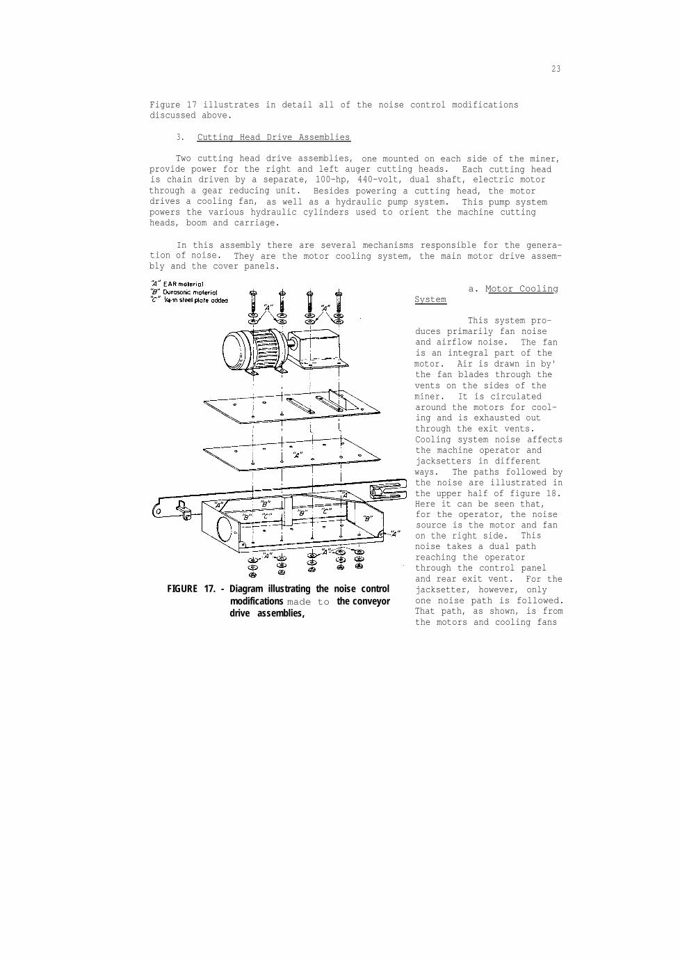
3. Cutting Head Drive Assemblies
Two cutting head drive assemblies, one mounted on each side of the miner,provide power for the right and left auger cutting heads. Each cutting headis chain driven by a separate, 100-hp, 440-volt, dual shaft, electric motorthrough a gear reducing unit. Besides powering a cutting head, the motordrives a cooling fan, as well as a hydraulic pump system. This pump systempowers the various hydraulic cylinders used to orient the machine cuttingheads, boom and carriage.
In this assembly there are several mechanisms responsible for the genera-tion of noise. They are the motor cooling system, the main motor drive assem-bly and the cover panels.
FIGURE 17. - Diagram illustrating the noise controlmodifications made to the conveyordrive assemblies,
a. Motor CoolingSystem
This system pro-duces primarily fan noiseand airflow noise. The fanis an integral part of themotor. Air is drawn in by'the fan blades through thevents on the sides of theminer. It is circulatedaround the motors for cool-ing and is exhausted outthrough the exit vents.Cooling system noise affectsthe machine operator andjacksetters in differentways. The paths followed bythe noise are illustrated inthe upper half of figure 18.Here it can be seen that,for the operator, the noisesource is the motor and fanon the right side. Thisnoise takes a dual pathreaching the operatorthrough the control paneland rear exit vent. For thejacksetter, however, onlyone noise path is followed.That path, as shown, is fromthe motors and cooling fans

24
KEY
FIGURE 18. - Diagram illustrating sources and paths ofcooling system noise and subsequentnoise control treatment.
directly through the frontexhaust vents. Additionally,the vibrating cover panelsproduce airborne noise whichcauses an increase in theoverall noise level of thejacksetters.
Motor cooling systemnoise is reduced by theincorporation of threeseparate modifications onthe miner. These modifica-tions, illustrated in thelower half of figure 18, are:
(1) Sealing the fourvents.
(2) Construction of anoperator barrier panel.
(3) Construction of aninternal barrier on the leftback end of the miner.
The following is a detaileddescription of each of thesemodifications:
(1) Sealing the Vents--The vents on the sides ofthe cover panels are sealedby removing the existinggratings and welding intheir place l/4" thick steelplates. The temperaturerise due to the sealing of
the vents is not critical. Tests which were conducted showed that after sev-eral hours of continuous operation, the temperature inside the panels rose toonly 60" C. The maximum temperature ratings for the motors, according to themanufacturer, is 150" C. Therefore, this test and the subsequent use of theminer in a working section of an underground mine show that temperature riseis not a problem.
(2) Construction of Operator Barrier Panel--In designing the operatorbarrier panel, consideration should be given to obstacles which could providedifficulty in constructing an effective cover. Protruding from the controlbox are a total of 11 levers, 6 on top, 5 on the bottom, that are to bemanipulated either up and down or in and out when operating the miner.Located on the left, angled toward the control box, is the hydraulic cylinder
25
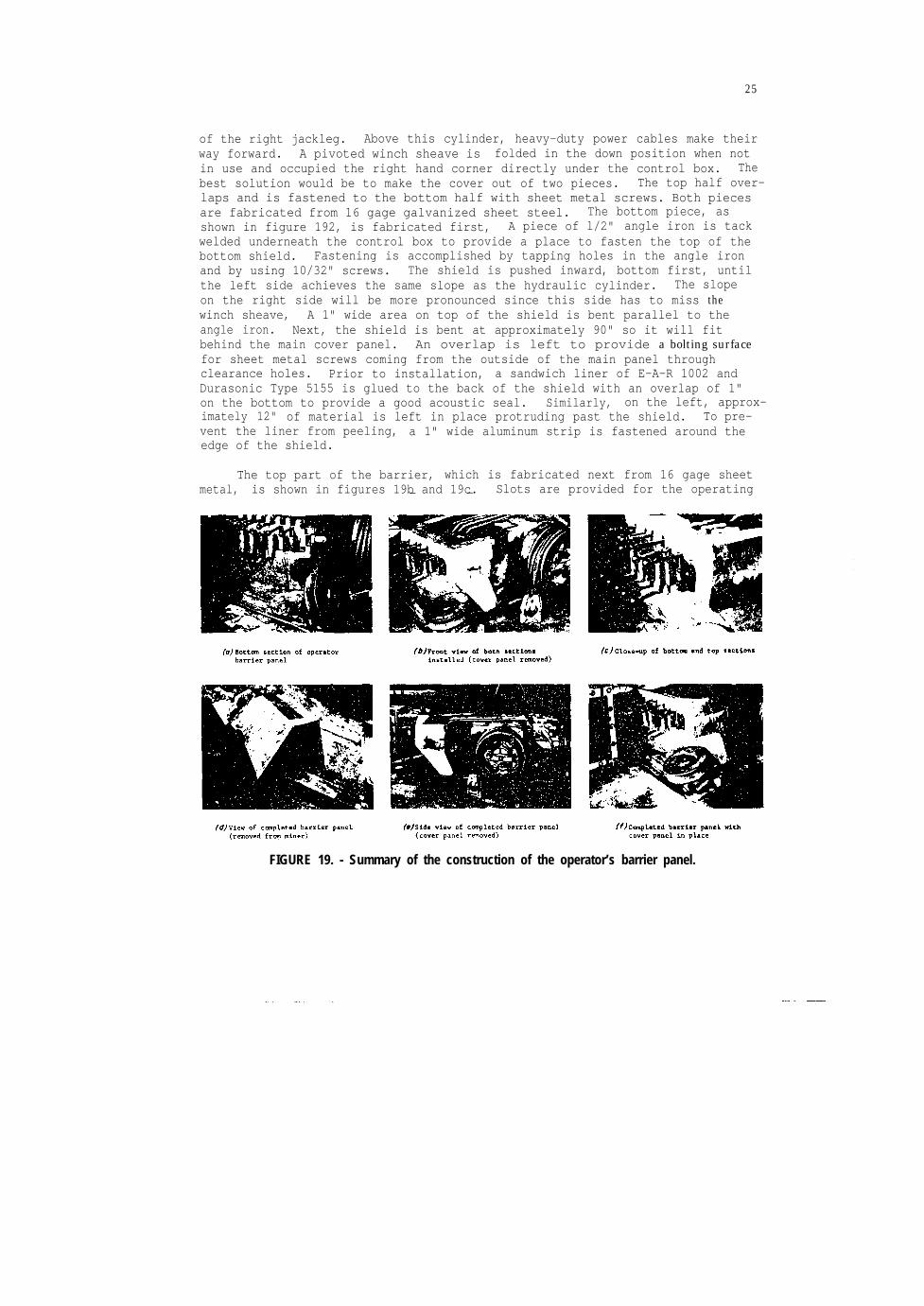
of the right jackleg. Above this cylinder, heavy-duty power cables make theirway forward. A pivoted winch sheave is folded in the down position when notin use and occupied the right hand corner directly under the control box. Thebest solution would be to make the cover out of two pieces. The top half over-laps and is fastened to the bottom half with sheet metal screws. Both piecesare fabricated from 16 gage galvanized sheet steel. The bottom piece, asshown in figure 192, is fabricated first, A piece of l/2" angle iron is tackwelded underneath the control box to provide a place to fasten the top of thebottom shield. Fastening is accomplished by tapping holes in the angle ironand by using 10/32" screws. The shield is pushed inward, bottom first, untilthe left side achieves the same slope as the hydraulic cylinder. The slopeon the right side will be more pronounced since this side has to miss thewinch sheave, A 1" wide area on top of the shield is bent parallel to theangle iron. Next, the shield is bent at approximately 90" so it will fitbehind the main cover panel. An overlap is left to provide a bolting surfacefor sheet metal screws coming from the outside of the main panel throughclearance holes. Prior to installation, a sandwich liner of E-A-R 1002 andDurasonic Type 5155 is glued to the back of the shield with an overlap of 1"on the bottom to provide a good acoustic seal. Similarly, on the left, approx-imately 12" of material is left in place protruding past the shield. To pre-vent the liner from peeling, a 1" wide aluminum strip is fastened around theedge of the shield.
The top part of the barrier, which is fabricated next from 16 gage sheetmetal, is shown in figures 19b and 19c.- - Slots are provided for the operating
FIGURE 19. - Summary of the construction of the operator’s barrier panel.
26
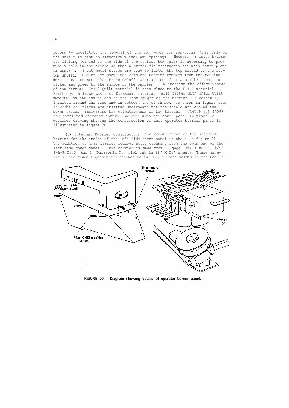
levers to facilitate the removal of the top cover for servicing. This side ofthe shield is bent to effectively seal any openings. However, a bulky hydrau-lic fitting mounted on the side of the control box makes it necessary to pro-vide a hole in the shield so that a proper fit underneath the main cover plateis assured. Sheet metal screws are used to fasten the top shield to the bot-tom shield. Figure 19d shows the complete barrier removed from the machine.Here it can be seen that E-A-R C-1002 material, cut from a single piece, isfitted and glued to the inside of the barrier. To increase the effectivenessof the barrier, Insul-Quilt material is then glued to the E-A-R material.Similarly, a large piece of Durasonic material, also fitted with Insul-Quiltmaterial on the inside and at the same height as the barrier, is carefullyinserted around the side and in between the winch box, as shown in figure 19e.In addition , pieces are inserted underneath the top shield and around thepower cables, increasing the effectiveness of the barrier, Figure 19f showsthe completed operator control barrier with the cover panel in place. Adetailed drawing showing the construction of this operator barrier panel isillustrated in figure 20.
(3) Internal Barrier Construction--The construction of the internalbarrier for the inside of the left side cover panel is shown in figure 21.The addition of this barrier reduces noise escaping from the open end of theleft side cover panel. This barrier is made from 16 gage sheet metal, l/4"E-A-R 2003, and 1" Durasonic No. 5155 cut in 18" X 28" sheets. These mate-rials. are glued together and screwed to two angle irons welded to the bed of
screws
FIGURE 20. - Diagram showing details of operator barrier panel.

27
FIGURE 21. - Diagram showing construction details of the internal barrier.
FIGURE 22. - Placement of the internal barrier for the left side of the miner.
28
the miner. The barrieris bowed to form a quarter cylinder and made to fitflush to the inside of the cover panel. Figure 22 shows the placement of theinternal barrier on the machine.
b. Main Motor Drive Assembly
At the request of the equipment manufacturer, this assembly was nottreated.
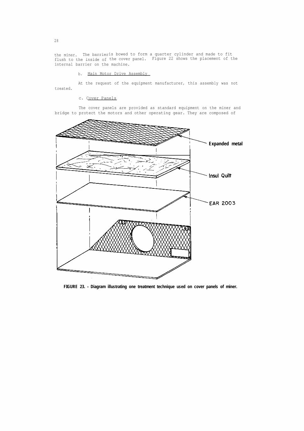
c. Cover Panels
The cover panels are provided as standard equipment on the miner andbridge to protect the motors and other operating gear. They are composed of
Expanded metal
FIGURE 23. - Diagram illustrating one treatment technique used on cover panels of miner.

29
l/4" steel and made to be bolted directly to the frame of the machine. Vibra-tions from the operating components can cause these panels to vibrate andradiate noise.
The acoustical treatment for the cover panels was designed with twothoughts in mind: first, the vibration of the covers must be damped, andsecond, the cover panel can act as a good acoustical enclosure with the instal-lation of sound absorbing material. Treatment begins by closing all panel
openings that are not needed for maintenance or lighting. The inside of everypanel is thoroughly cleaned by sand blasting. A piece of E-A-R 1002, cut tofit, is then glued to the inside surface using an epoxy adhesive (fig. 23).Next, a properly sized piece of fiberglass material (having an impervious frontlayer) is glued to the E-A-R material. An expanded metal screen is thenplaced on top of the fiberglassand tack welded to the cover panels around the

30
edges. The expanded metal screen is installed to protect the fiberglass whenthe panels are removed for maintenance.
An alternate method that can be used for installing the fiberglassmaterial is shown in figures 24 (a through c). After cleaning the panels, aseries of metal studs are welded to the inside surface. The E-A-R material isglued to the panel as before except that small clearance holes are cut intothe material for the studs, as shown in figure 24a. Fiberglass material withprotective screen, shown in figure 24b, is then pushed onto the studs. Rubberretaining caps are used on the studs to keep the fiberglassand screen in place(fig. 24c). For some of the panels, small areas of the screen and fiberglassare removed to give clearance for the motor and gear assemblies.
FIGURE 25. - Summary of technique s used in mounting cover panels on miner and bridgeconveyor.

31
In replacing the modified cover panels on the miner and bridge conveyor,precautions are taken to vibrationally isolate them from the machine frame asmuch as possible. Every mounting bolt used has a specially fabricated iso-lating washer as shown in figure 25a. When installing the bolts, regularmetal washers are used on top of the isolating washers (fig. 25b. Tofurther isolate the covers, E-A-R pads are constructed and glued to every
'cover panel mounting bracket (fig. 25c).the cover panels shows them to be damped,
Thus, the final configuration ofisolated from frame vibration and
acting as noise absorbing, high transmission loss acoustical enclosures.
4 . Winch System
The winch system on the Wilcox auger miner is used in conjunction withmetal jacks to position and advance the miner across the coal face. Thissystem is composed of two 40' lengths of 5/8" wire rope wrapped around drumson each side of the miner. The drums are gear driven by the main drive-trainmotors. Noise measurements were taken both without the winch system in oper-ation and with the winches energized (tension on the cables). Results showedthat the contribution of noise generated by the winch system to the overallnoise level is negligible. Because of these results, acoustical modifica-tions are felt to be unnecessary.

32
5. The Completed Mark 20 Miner System
The completed Wilcox Mark 20 miner and bridge conveyor employing all thenoise control modifications described in this report are shown in figures 262and 26b. From the photographs, it can be seen that none of the noise controltechniques used have drastically altered the physical dimensions of the minerand bridge. Except for the conveyor damping strips, a casual observer wouldexperience difficulty in recognizing the difference between a noise controlledand an unmodified machine, The difference, however, would become readilyapparent once the machines were operated. This difference, the noise reduc-tion, will be discussed for both the surface and underground environments inthe following sections.
RESULTS--SURFACE
All of the acoustic data presented in this section were measured inaccordance with the procedures and instrumentation specified in the sectionstitled "Instrumentation" and "Procedure." The miner and associated bridgeconveyor were operated in an unloaded state; that is, the system was neithercutting nor transporting coal.
1. Reverberation Measurements
In order to utilize the above ground noise data in predicting undergroundmachine noise levels, an acoustical characterization of the above and belowground environments was performed. This was done using an impulsive noisesource (bursting balloons) and measuring the reverberation or decay times ofthe sound field, in l/3 octave bands, with the miner in place. The resultingA-weighted reverberation time for the surface work area was 1.3 seconds. Theunderground A-weighted reverberation time, as measured in a low coal entry,was significantly less, averaging 0.8 second. This indicates that the sur-face environment was acoustically less absorptive than the underground environ-ment. Thus, the machine noise levels as measured in the surface work areawould be higher than those measured, under the same machine operating condi-tions, in an underground coal mine. This difference in the above and belowground noise levels will, of course, vary with different locations around themachine, being a function of the relative strengths of the direct and reflectedsound fields.
2. Noise Level Reductions--Miner
Figure 27 illustrates the A-weighted sound level reductions measured atnine positions around the miner. These measurements were made with all minersystems in operation and no bridge conveyor attached. In the figure, the fol-lowing notation is used: bracketed numbers < > indicate before modificationsound levels. Numbers in parentheses ( ) indicate after modification soundlevels, while unbracketed numbers are the resulting dBA noise reductions. Ascan be seen, the noise reductions vary in magnitude around the miner, reachinga maximum at the operator's position of 10.1 dBA (103.0 dBA before, 92.9 dBAafter). The reductions measured for the right and left jacksetters' positionsare 6.4 dBA (98.5 dBA before, 92.1 dBA after) and 7.3 dBA (99.5 dBA before,92.2 dBA after), respectively.

Operator position
Right jack setter position
\
Left jack setter position
KEY
Operator position
Right jack setter position
\

34
To further characterize the noise emitted from the miner, C-weightednoise data is given in figure 28. Here the same before and after notation isused as in figure 27. The dBC noise reductions are, for the most part, lessthan the dBA reductions, being 8.9 dBC for the operator, 5.0 and 5.5 dBC forthe rightandleft jacksetters' positions. Table 2 summarizes the A- and C-weighted noise level measurements obtained around the miner.
TABLE 2. - Noise levels (RTA output) around miner before and aftermodifications--everything on miner in operation;
no bridge conveyor
Position
12 Jack-
setter34567 Operator89 Jack-
setter
Average dBA Average dBA Average dBC Average dBCbefore after Reduction before after Reduction
modifi- modifi- in dBA modifi- modifi- in dBCcation cation cation cation100.0 99.3 0.7 102.6 101.6 1.0
99.5 92.2 7.3 101.3 95.8 5.5101.1 91.9 9.2 103.2 95.9 7.3103.0 93.1 9.9 105.2 96.8 8.4101.7 95.4 6.3 103.7 97.8 5.9102.7 92.9 9.8 104.8 96.8 8.0103.0 92.9 10.1 105.3 96.4 8.999.8 91.1 8.7 102.3 94.8 7.5
98.5 92.1 6.4 100.8 95.8 5.0
The octave band spectrum for each of the workers' positions is given infigure 29. Referring to the before curves in each graph, it is apparent thatmost of the sound energy, before modification, is evenly distributed with the125 to 2,000 Hz frequency bands, falling off at about a 10 dB/octave ratebelow 125 Hz and 7dB/octave above 2,000 Hz . The noise reduction obtained,which is shown in the shaded region in each graph, is maximum within thefrequency bands of 125 to 4,000 Hz. Thus, the noise reduction achieved lieswithin the frequency range which is most critical to human hearing. Appendix Aprovides a complete description of the acoustical data, giving the beforeand after 1/3 octave band spectra as measured at all positions around theminer.

35
3. Vibration Level Reductions--Miner
Vibration levels (acceleration) were measured before and after noisecontrol treatment of the miner. Figure 30 shows the results obtained onseveral parts of the machine surface. These measurements were made with allminer systems operating and no bridge conveyor attached. Reductions in vibra-tions were significant, averaging 16 dB (re 30 µg) for the nine positions.Table 3 summarizes the A- and C-weighted vibrational level measurementsobtained on the miner.
TABLE 3. - Acceleration measurements on miner before and after modifications--everything on miner in operation; no bridge conveyor
Position
123456789
Average dBAbefore
modifi-cation105.1
NOTE .--All an values are referneced to µg.
100.2103.2108.4108.7110.8102.2100.9103.2
Average dBAafter
modifi-cation
83.082.984.180.581.897.897.783.287.1
Reductionin dBA
22.117.319.127.926.913.04.5
17.716.1
Average dBCbefore
modifi-cation104.799.9
116.3108.0108.7109.6102.1100.5103.0
Average dBCafter
modifi-cation
84.086.985.888.790.898.698.285.688.4
Reductionin dBC
20.413.030.519.317.911.03.9
14.914.6
Vibrational analysis in l/3 octave bands indicated that most of the reduc-tion occurred in the 250 to 8,000 Hz frequency range. Many of the vibrationspectra showed unusually large peaks in the 63 Hz l/3 octave band. The phe-nomenon was investigated and found to be caused by electrical interference.Mathematical corrections for these electrically induced peaks were made in thevibrational spectra. Appendix B gives the complete l/3 octave vibrationalanalysis done on the miner.

Left jack setter posit ion
FREQUENCY, Hz
FIGURE 29. - Octave band spectra of noise at each of three FIGURE 30. - Vibration levels (re 30 pg) at several posi-worker positions, before and after modifications. tions on the miner, before and after modifications;

37
FREQUENCY, Hz
FIGURE 31. - A-weighted noise levels and octave band spectra around bridge conveyor, beforeand after modifications;

38
4. Acoustical Data--Bridge Conveyor
Noise and vibration levels were measured before and after noise controlmodifications at various locations around and on the bridge conveyor.Figure 31 shows the before and after sound levels. For these measurements,all miner systems and the bridge conveyor were in operation. Resulting A-weighted noise reductions at all monitored locations ranged from 7.5 to 11.1dBA with a mean value of 9.2 dBA. Similarly, the C-weighted sound pressurelevels are given in figure 32. Here again the dBC noise reductions were some-what less than the corresponding dBA values, ranging in value from 4.8 to 7.5dBC with a mean of 6.4 dBC. Table 4 summarizes the dBA and dBC acousticaldata.
Several octave band spectra included in figure 31 describe the resultingnoise level reduction as a function of frequency. Here the frequency distri-bution of the obtained reductions is shifted one octave, relative to thatobtained for the miner, being maximum in the 250 to 4,000 Hz frequency bands.Appendix C gives a complete listing of all before and after l/3 octave bandspectra measured around the bridge conveyor.
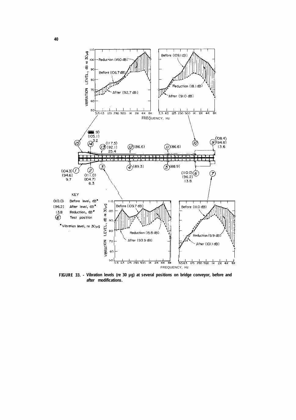
Results of vibration levels measured before and after noise control modi-fications are presented in figure 33. Appreciable reductions are evidenced atall but one of the positions monitored. The mean reduction in vibration levelwas approximately 12 dB (re.30 µg. Table 5 lists the A- and C-weighted vibra-tional level measurements and reductions obtained. The octave band vibra-tional data for all measured positions can be found in appendix D.
(106 .0 )(106 .0 )( 9 8 . 9 )( 9 8 . 9 )
FIGURE 32. - C-weighted noise levels and octave band spectra around bridge conveyor, beforeand after modifications;

39
TABLE 4. - Noise levels (RTA output) around bridge conveyor before and aftermodifications--everything on both miner and bridge conveyor
in operation
Position
123456789
101112131415
Average dBAbefore
modifi-cation106.7105.0104.8
103.6102.4104.8101.6103.7
104.1104.9106.6
Average dBAafter
modifi-cation
97.396.094.892.592.894.093.797.392.992.692.293.195.095.797.4
Reductionin dBA
9.49.0
10.0
Average dBCbefore
modifi-cation108.1106.0105.5
9.6 105.18.7 104.47.5 105.68.7 103.4
11.1 105.0
9.1 105.19.2 106.09.2 108.0
Average dBCafter
modifi-cation100.699.298.196.397.999.399.1
100.398.698.696.396.498.098.9
100.8
Reductionin dBC
7.56.87.4
5.85.35.34.86.4
7.17.17.2
TABLE 5. - Acceleration measurements on bridge conveyor before and aftermodifications--everything on both miner and bridge
conveyor in operation
123456789
1011121314
cation105.9112.3109.5
110.8111.7
cation95.7
105.794.688.687.894.4
100.2
109.3109.4
94.490.487.387.793.5
106.2107.1
15 108.3 93.4103.2
NOTE .--All dB values are reference
Reductionin dBA
10.26.6
14.9
Average dBCbefore
modifi-cation104.3111.0109.7
16.4 110.011.5 111.0
14.9 108.419.0 109.1
13.6 117.513.0 101.914.9 106.7
Average dBCafter
modifi-cation
94.6104.793.989.388.996.2
101.1
94.891.086.686.692.1
105.192.7
Reductionin dBC
9.76.3
15.8
13.89.9
13.618.1
25.413.214.0
to 30 µg.
40
FREQUENCY, Hz
FREQUENCY, Hz
FIGURE 33. - Vibration levels (re 30 µg) at several positions on bridge conveyor, before andafter modifications.

FIGURE 34. - Total sound power of miner (re 10-12 watts) inoctave bonds, before and after modifications.
41
5. Sound Power Mea-surements--Miner
The total sound poweroutput of the miner wasmeasured using the methoddescribed in the sectiontitled "Procedure." Thebefore and after modifica-tion results are showngraphically in figure 34 andnumerically in table 6. Ascan by seen, the acousticenergy output of the machinewas reduced the most in the250 to 4,000 Hz frequencyregion. The overall A-weighted sound power outputof the unmodified miner was116.8 dB,A (re 10-12 watts)while the sound powermeasured after modificationswas 109.9 dB,A, for a reduc-tion of 6.9 dBA. Alter-nately, the sound poweremissions can be consideredfrom a viewpoint of acoustic
watts. In this perspective, the A-weighted, premodification, acoustic poweroutput of the miner was 0.5 watt while the post-modification power output was0.1 watt, for a reduction of 0.4 acoustical watt. Thus, the noise controlmodifications were responsible for an 80 percent reduction in the total soundpower emitted by the miner.
TABLE 6. - Sound power levels measured before and after acousticalmodification of Wilcox miner
Frequency dBp beforemodifications
83.797.9
108.7111.8111.6111.8111.1107.296.2
116.8 (dBpA)118.4 (dBpC)
NOTE. --All dBp values referenced to 10
31.563.0
125250500
1,0002,0004,0008,000A-weightC-weight
dBp aftermodifications
81.7100.0106.3108.2105.4105.8102.698.091.1
109.9 (dBpA)113.2 (dBpC)
-12 watts.
dBp reduction
8.0-2.12.43.66.26.08.59.25.16.9 (dBpA)5.2 (dBpC)

42
RESULTS--UNDERGROUND
After the completion of the modification program, the miner and bridgeconveyor were shipped back to the owners, Buchanan & Sons Coal Company. Whenthe miner and bridge were put in use on an active section, arrangements weremade to conduct the followup surveys. This equipment has been in continuousunderground operation for more than 1 year.
During this interval of time, two separate noise surveys were conducted.To estimate the effectiveness of the modifications, the data collected onthese surveys was compared to the data obtained during a premodification sur-vey conducted on the same machine. This premodification or reference surveywas performed during October 1974.
In general, the comparison shows that a consistent noise reduction hasbeen achieved and that no significant loss in production has occurred becauseof the modifications.
1. Survey Procedure
Before any noise measurements were taken, a quick visual inspection ofthe miner and bridge was made each time to see if all of the modificationswere intact. After the conditions of the modifications were noted, the noisesurvey was conducted.
At the conclusion of the noise survey, discussions were held with themachine crew and other mine officials. The purpose of these meetings was todetermine their subjective reactions to the modifications and to note anysignificant changes in the production record of the machine.
as other locations aroundthe miner and bridge (fig. 35)to indicate the generalsound field around the equip-ment in the undergroundenvironment. Noise levelsduring the different operat-ing modes of the machinewere also measured. Noiselevel data was obtained witha General Radio 1565-A(S/N 4481) sound level meter.Tape recordings were alsomade for subsequent fre-
FIGURE 35. - Underground noise measurement positionsquency analysis at the labo-ratory. Before any measure-
around miner and bridge conveyor, ments were taken, all

43
acoustical equipment wereproperly calibrated using a1,000 Hz signal at 114 dB re20 µN/M2.
2. Results
As previously stated, areference noise survey wasconducted on the miner andbridge before they were modi-fied, Results from that sur-vey showed the noise levelsto be quite high: 102 dBAat the operator's position,and 104 dBA at the rightjacksetter's position.Measurements taken duringthe first followup surveyindicated noise levels of97 dBA at the operator'sposition and 102.5 dBA atthe right jacksetter's posi-tion. Data obtained duringSeptember 1976 indicated
that the noise at the operator's and jacksetter's positions remained the sameat 97 dBA and 102 dBA, respectively. Figure 36 shows the l/3 octave bandspectra of the noise at the operator's position, before and after the modifica-tion program. It is a well-known fact that the accuracy and repeatibility ofthe real time analyzer system, Type I, is more precise than a sound levelmeter which is Type II; however, due to underground sampling procedures thatwere very short in duration, the real time analyzer spectrum shown in fig-ure 36 may not be representative of the typical noise spectrum of the miner.Table 7 compares the sound level meter data obtained during the three surveys.
TABLE 7. - Noise level of unmodified and modified minerand bridge conveyor, cutting coal
Noise level of Noise level of modifiedunmodified machine (dBA) Average
Measuring location machine (dBA), First survey Second survey noisereference survey (9/75) (9/76) reduction
I (10/74) IOperator........... 101.9±1.5 96.7±1.2 97.0±0.7 5.0 dBARight jacksetter... 103,8±2.1 102.5±1.8 101.7±0.6 1.7 dBA
Referring to position 5 in table 8 and position 18 in table 9, the dataindicates that the dump point of the two chain conveyors is the loudest areaon the equipment when running in an unloaded condition. It should be remem-bered that when the equipment is cutting air, no material is being conveyed

44
and the noise levels will be slightly higher especially at the drive sprocketof either conveyor. Measurements taken underground at position 5 during anormal mining cycle showed a noise level of 96 dBA when running empty and93 dBA when running full of coal.
TABLE 8. - Noise contours around miner, unloaded condition
Position*2 (left jacksetter).......3 .........................4 .........................5 .........................6 .........................
95-979799-10099-10094-95949392-93
919192-939692-9390-9190-91
7 (operator)..............8 . . . . . . . . . . . . . . . . . . . . . .9 (right iacksetter)...... 89-90*Refer to figure 35 for the measurement locations around the miner and bridge
conveyor.
Miner on, bridge on Miner on, bridge off
TABLE 9. - Noise contours around bridge conveyor, unloaded condition
Position*. . . . . . . . . . . . . . . . . . . . . . . .
13 ........................14 ........................15 ........................16 ........................17 .......................18 ........................19 ........................20 ........................21........................22 ........................23 ........................
Bridge on, miner on99-10097 -9896-9796-9796-9796-97
102-10396-9896-9795-96979798-99
Bridge on, miner off97 -98979696-9796-9797
102-10397989695-969796-9725........................
*Refer to figure 35 for the measurement locations around the miner and bridgeconveyor.
As mentioned previously, the noise reduction obtained at the jacksetter'sposition was minimal. The noise levels for these workers are primarily influ-enced by the augers ripping the coal from the seam. Future plans include con-ducting an analysis program on a set of augers to determine their vibrationalresponse and to determine the airborne noise generated by them under a loadedcondition. Modifications will then be made to the augers in an attempt toreduce this noise. After the laboratory testing is completed, these will beused with the modified miner and bridge conveyor. Underground surveys willbe conducted to determine the effectiveness of the treated augers in reducingthe noise levels at the jacksetter's position.

45
DISCUSSION OF RESULTS
The modifications to the Wilcox miner and bridge conveyor have proventheir effectiveness in terms of noise reduction and durability in the under-ground environment. The reduction in noise at the operator's position, from102 to 97 dBA, as measured with a sound level meter, represents a doubling ofthe allowable operating time from 1.5 to 3 hours. A similar retrofit programcan be initiated by interested coal companies using the techniques describedin this report to reduce excessive noise levels from the Mark 20 system.
A retrofit noise abatement package is available from the equipmentmanufacturer that can be installed on existing Wilcox machines. Additionally,this noise control package can be ordered with all new equipment purchases.The cost of these modifications (approximately $8,400) will raise the cost ofthe miner-bridge conveyor system slightly, but the reduction in noise willmean an increase in the permitted operating time which will result in anincrease in total coal production.
Another specific example which demonstrates the effectiveness of thesemodifications is a Mark 20 system retrofitted by Fairchild and in use in acentral Pennsylvania coal mine. The noise levels, measured at the operator'sposition before any modifications, ranged from 96 to 102 dBA with a totalnoise exposure index (NEI) of 1.32. After installation of the noise controlpackage, the operator's noise exposure ranged from 96 to 99 dBA with a totalNEI of 0.75.
It should be realized that the noise control techniques discussed may beused successfully in modifying other mining equipment with similar noisesources.
Many types of mining equipment have component systems which are similarto those treated on the Wilcox miner and bridge. Continuous miners and load-ing machines use chain conveyors to transport the coal from the active face tothe haulage units waiting at the end of the machine. Damping-isolation strips,similar to those installed on the Mark 20 system, could be applied to continu-ous miners and loading machines.
Also, various components (that is, motors, pumps, etc.) can be isolatedfrom the machine frame to eliminate excessive vibrations causing an increasein the overall noise level. This would be best accomplished during the equip-ment manufacturing process when the proper isolator can be chosen andinstalled easily into the component system.
Finally, the use of barriers, such as the one installed at the operator'sposition, can be an effective means to block the transmission path of noisegenerated by different machine components.
As shown by this report, these modifications can be accomplished in aretrofit fashion. However, noise reduction could be achieved more effectivelyif these acoustical modifications were to be designed into the miningequipment.

46
APPENDIXES
The appendixes, A through D, have been included to allow others attempt-ing this work to compare their results to ours. Third octave band noisespectra at various locations around the miner and bridge conveyor are givenin appendixes A and C, respectively. Third octave band vibration spectra atvarious locations on the miner and bridge conveyor are given in appendixes Band D, respectively, In each appendix, the format for presenting the data isas follows:
Spectra after modifications - x--x--x
Noise reduction
Position at whichspectra was obtained - Marked with a number on
accompanying diagram ofmachine

47
APPENDIX A. --ONE-THIRD OCTAVE BAND NOISE MEASUREMENTS AT VARIOUSLOCATIONS AROUND THE MINER, UNLOADED, BEFORE AND AFTER
NOISE CONTROL MODIFICATIONS (9 POSITIONS)
FIGURE A-2. - Noise spectrum at position 2(left jacksetter).
FIGURE A-4. - Noise spectrum at position 4(left rear corner).

48
FIGURE A-7. - Noise spectrum at position 7(operator);
FIGURE A-8. - Noise spectrum at position 8(right winch).

49
FIGURE A-9. - Noise spectrum at position 9( r igh t j ackse t te r ) .

50
APPENDIX B.--ONE-THIRD OCTAVE BAND VIBRATION MEASUREMENTS AT VARIOUSLOCATIONS ON THE MINER, UNLOADED, BEFORE AND AFTER NOISE
CONTROL MODIFICATIONS (9 POSITIONS)
51
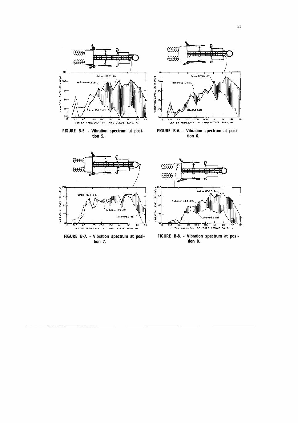
FIGURE B-5. - Vibration spectrum at posi-tion 5.
FIGURE B-6. - Vibration spectrum at posi-tion 6.
FIGURE B-7. - Vibration spectrum at posi- FIGURE B-8, - Vibration spectrum at posi-tion 7. tion 8.

52
C E N T E R F R E Q U E N C Y O F T H I R D O C T A V E B A N D , H I

53
APPENDIX C.--ONE-THIRD OCTAVE BAND NOISE MEASUREMENTS AT VARIOUSI&CATIONS AROUND THE BRIDGE CONVEYOR, UNLOADED, BEFORE AND AFTER
NOISE CONTROL MODIFICATIONS (11 POSITIONS)

54
FIGURE C-9. - Noise spectrum at position 13. FIGURE C-10. - Noise spectrumtion 14.
FIGURE C-l 1; - Noise spectrum attion 15.
BAND, Hz
at posi-
posi-

55
APPENDIX D.--ONE-THIRD OCTAVE BAND VIBRATION MEASUREMENTS AT VARIOUSLOCATIONS ON THE BRIDGE CONVEYOR, UNLOADED, BEFORE AND AFTER
NOISE CONTROL MODIFICATIONS (10 POSITIONS)
FIGURE D-l. - Vibration spectrum at posi-tion 1.
FIGURE D-2. - Vibration spectrum at posi-tion 2.
FIGURE D-3. - Vibration spectrum at posi-tion 3.
FIGURE D-4, - Vibration spectrum at posi-tion 6.

56
FIGURE D-7. - Vibration spectrum at posi- FIGURE D-8. - Vibration spectrum at posi-tion 10. tion 13.

57
FIGURE D-9. - Vibration spectrum at posi- FIGURE D-10. - Vibration spectrum at posi-tion 14. tion 15.
U.S. GOVERNMENT PRINTING OFFICE: 1977-703-001/96