nodea+_lte_pa-105510.2-en.gb_.pdf
DESCRIPTION
NodeATRANSCRIPT
Coverage Solution for Interleaved Sub-bands within Multiple Frequency Bands
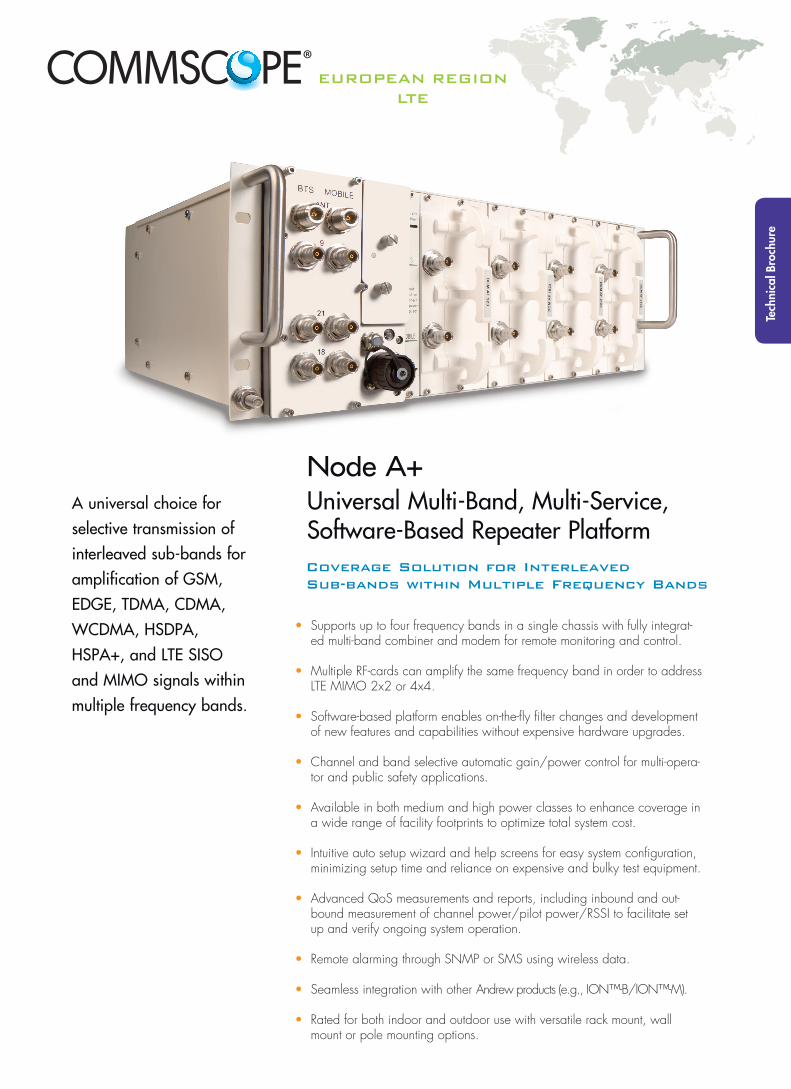
Node A+Universal Multi-Band, Multi-Service, Software-Based Repeater Platform
• Supports up to four frequency bands in a single chassis with fully integrat-ed multi-band combiner and modem for remote monitoring and control.
• Multiple RF-cards can amplify the same frequency band in order to address LTE MIMO 2x2 or 4x4.
• Software-based platform enables on-the-fly filter changes and development of new features and capabilities without expensive hardware upgrades.
• Channel and band selective automatic gain/power control for multi-opera-tor and public safety applications.
• Available in both medium and high power classes to enhance coverage in a wide range of facility footprints to optimize total system cost.
• Intuitive auto setup wizard and help screens for easy system configuration, minimizing setup time and reliance on expensive and bulky test equipment.
• Advanced QoS measurements and reports, including inbound and out-bound measurement of channel power/pilot power/RSSI to facilitate set up and verify ongoing system operation.
• Remote alarming through SNMP or SMS using wireless data.
• Seamless integration with other Andrew products (e.g., ION™-B/ION™-M).
• Rated for both indoor and outdoor use with versatile rack mount, wall mount or pole mounting options.
A universal choice for
selective transmission of
interleaved sub-bands for
amplification of GSM,
EDGE, TDMA, CDMA,
WCDMA, HSDPA,
HSPA+, and LTE SISO
and MIMO signals within
multiple frequency bands.
Tech
nica
l Bro
chur
e
EuropEan rEgIonLTE
Electrical
Number of supported RF cards (see table 1)
Node A2+ . . . . . . . . . . . . . . . . . . 2 Node A4+ . . . . . . . . . . . . . . . . . . 4
Number of supported sub-bands per rack
Node A2+ . . . . . . . . . . . . . . . . . . 24*
Node A4+ . . . . . . . . . . . . . . . . . . 48*
Frequency range and RF output power . . . . . . . . . see table 1
Bandwidth available in Uplink and Downlink per rack, MHz Node A2+ . . . . . . . . . . . . . . . . . . up to 120 . . . . . . . . . . . . . . . . . . (see table 2 for details) Node A4+ . . . . . . . . . . . . . . . . . . up to 240 . . . . . . . . . . . . . . . . . . (see table 2 for details)
Gain in Uplink and Downlink. . . . . . . . . . . . . . . . see table 1
Gain adjust range, dB . . . . . . . . . . . . . . . . . . 30 in steps of 1
Filter selection step size, kHz . . . . . . . . . . . . . . . . 10
Output Power step size in Powermode, dB . . . . . . 1
Output Power accuracy over all conditions, dB . . . ±2
Maximum Input Power without damage, dBm . . . . +10
Maximum Input Power without overdrive, dBm . . . -20
P-1dB, dBm Uplink . . . . . . . . . . . . . . +35 RF card AX23 - AX25 Downlink . . . . . . . . . . . . . +32 RF card AX35 - AX36 Downlink . . . . . . . . . . . . . +42
OIP3, dBm Uplink . . . . . . . . . . . . . . +52 RF card AX23 - AX25 Downlink . . . . . . . . . . . . . +48 RF card AX35 - AX36 Downlink . . . . . . . . . . . . . +63
Noise figure @ maximum gain, dB Uplink . . . . . . . . . . . . . . 4.0 Downlink . . . . . . . . . . . . . 4.0 @ minimum gain, dB Uplink . . . . . . . . . . . . . . 9.0 Downlink . . . . . . . . . . . . . 16.0
Delay, µs Standard filter set . . . . . . . . 6
Power supply Standard . . . . . . . . . . . . . 100 to 240 Vac Option . . . . . . . . . . . . . . 36 to 110 Vdc
Power consumption, Watts Node A2+ chassis . . . . . . . . 70 Node A4+ chassis . . . . . . . . 120 RF card AX23 - AX25. . . . . . . 70 RF card AX35 - AX36. . . . . . . 145
Antenna port connectors . . . . . . . . . . . . . . . . . . N Female
Spurious Emissions, dBm . . . . . . . . . . . . . . . . . . acc. to GSM05.05, 3GPP45.005, 3GPP25.106, 3GPP36.106
* Valid for sub-band bandwidth up to 5 MHz.
Mechanical
Height, width, depth, mm (in) Node A2+ . . . . . . . . . . 177.0 x 351.2 x 462.8 . . . . . . . . . . . . . . . . . . . . . . .(7 x 13.8 x 18.2) Node A4+ . . . . . . . . . . 177.0 x 482.3 x 462.8 . . . . . . . . . . . . . . . . . . . . . . .(7 x 19 x 18.2))
Weight, kg (lb) Node A2+ . . . . . . . . . . 11 (24) Node A4+ . . . . . . . . . . 12.5 (27.5) RF card AX23 - AX25. . . . . 3 (6.5) RF card AX35 - AX36. . . . . 4.5 (10)
Environmental
Operating temperature range, °C. . . . . . . . . . . . . -33 to +50
Ingress protection . . . . . . . . . . . . . . . . IP65 (Fans: IP55)
Acoustic Noise, dB(A) . . . . . . . . . . . . . . . . 47 @ 25°C . . . . . . . . . . . . . . . . 55 @ 50°C
All figures are typical values and refer to the antenna ports of the RF card. The loss of the integrated RF combiner section (Option) is typically 0.5 to 1.0 dB.
Features
Items measured . . . . . . . . . . . . . . . . Measurement of pilot power, synch. power, Ec/Io, BCCH power, channel power, RSSI, and system identification.
Statistic collection . . . . . . . . . . . . . . . . Collecting data (min., max., average, standard deviation) of items measured in a 15 minutes interval.
Auto configuration . . . . . . . . . . . . . . . . Setup based on downlink power requirements, not gain. Uplink gain is automatically setup based on the downlink settings.
Access . . . . . . . . . . . . . . . . Web browser based local access and remote access. Packet data and circuit switched data options. OMC connectivity via SNMP.
External alarms . . . . . . . . . . . . . . . . Up to 5 alarms, active high or low configurable via software.
Interference Analysis Database . . . . . . . . . . . . . . Event triggered database to identify interference signals in terms of frequency, power level, duration, etc.
Battery Backup . . . . . . . . . . . . . . . . Built-in Modem Battery Backup for Mains Supervision
Specifications Node A+ RF Enhancer

Table 1: RF Card Options
Modulation scheme RF CardUL Frequency,
MHzDL Frequency,
MHzMax. Gain,
dBUplink Composite Output Power, dBm* Downlink Composite Output Power, dBm*
LTE 800**AF 824
832 to 862 791 to 82180 27 24
AF 835 90 27 35
EGSM 900, UMTS 900,LTE 900**
AF 923880 to 915 925 to 960
8025 (GSM)
27 (UMTS, LTE)23 (GSM)
25 (UMTS, LTE)
AF 936 9025 (GSM)
27 (UMTS, LTE)36 (GSM, UMTS, LTE)
GSM 1800,LTE 1800**
AF 18231710 to 1785 1805 to 1880
8026 (GSM)27 (LTE)
23 (GSM)25 (LTE)
AF 1835 9226 (GSM)27 (LTE)
35 (GSM, LTE)
UMTS 2100,LTE 2100**
AF 21251920 to 1980 2110 to 2170
8228 (UMTS)27 (LTE)
25 (UMTS, LTE)
AF 2135 9228 (UMTS)27 (LTE)
35 (UMTS, LTE)
LTE 2600**AF 2625
2500 to 2570 2620 to 269082 27 25
AF 2635 92 27 35
* Output power per carrier (dBm) = composite output power (dBm) - 10 x log (no. of carriers)
** LTE and UMTS uplink composite output power (dBm) valid for sub-bands ≤ 10 MHz, slight reduction of uplink composite output power for sub-bands > 10 MHz only
The Node A+ RF Cards convert the RF into digital signals and transfer them to the Node A+ rack for digital filtering. The digital architecture allows sub-band filtering and is shared between all RF Cards inserted into the Node A+ rack. The Node A2+ can provide up to 24 filter resources (up to 5 MHz each) and the Node A4+ can provide up to 48 filter resources. When the sub-band bandwidths are greater than 5 MHz, the filter resources are grouped together, without phase or amplitude ripple, where the sub-band is defined by a start and stop frequency. The total number of used filter resources is determined by adding the number of filter resources required for each sub-band.
For example, if there are three sub-bands with 4 MHz for the first sub-band, 11 MHz for the second sub-band, and 20 MHz for the third sub-band, then 1 filter resource is required for the first sub-band, 3 filter resources are required for the second sub-band and 4 filter resources are required for the third sub-band. The total number of used filter resources in this example is 8. However, the maximum available band-width (Node A2+ 100 MHz and Node A4+ 200 MHz) will only be achieved with sub-band bandwidths of integer multiple of 5 MHz.
Detailed System Description
Table 2: Bandwidth available in UL and DL per rack, MHzSub-Band Bandwidth [MHz] Filter Resources
0.01 to 5.00 1
5.01 to 10.00 2
10.01 to 15.00 3
15.01 to 20.00 4
20.01 to 25.00 5
25.01 to 30.00 6
30.01 to 35.00 7
35.01 to 40.00 8
40.01 to 45.00 9
45.01 to 50.00 10
50.01 to 55.00 11
55.01 to 60.00 12
60.01 to 65.00 13
65.01 to 70.00 14
70.01 to 75.00 15
Example: Filter Resources Allocation Node A4+ (up to 5 MHz wide)
∆ Operator A GSM 900 1 Band 6 MHz
∆ Operator A GSM 1800 1 Band 32 MHz
∆ Operator A UMTS 2100 1 Band 20 MHz
∆ Operator B GSM 900 1 Band 14 MHz
∆ Operator B DCS 1800 1 Band 23 MHz
∆ Operator B UMTS 2100 1 Band 20 MHz
∆ Operator C GSM 900 1 Band 15 MHz
∆ Operator C DCS 1800 1 Band 20 MHz
∆ Operator C UMTS 2100 1 Band 20 MHz
∆ Unused filter resources: 12

www.commscope.com
© 2012 CommScope, Inc. All rights reserved.
Visit our website at www.commscope.com or contact your local CommScope representative or BusinessPartner for more information.
All trademarks identified by ® or ™ are registered trademarks or trademarks, respectively, of CommScope, Inc.
Bulletin PA-105510.2-EN.GB (11/12)
Table 3: Node A+ Ordering Guide
Description Part-Number
Required System Rack:Node A2+ 7640794Node A4+ 7640793
Required Power Supply:Power Supply Unit AC IN 100-240V 7605769-00Power Supply Unit DC IN 36-110V 7609268-00
Required, at least one
RF cards:
DCM AF 824 7621773-01DCM AF 835 7621771-01DCM AF 923 7562492-01DCM AF 936 7562493-01DCM AF 1823 7562494-01DCM AF 1835 7562495-01DCM AF 2125 7562496-01DCM AF 2135 7562497-01DCM AF 2625 7621749-01DCM AF 2635 7621747-01
Optional Number of Dummy Cards (each empty slot must be filled with a Dummy Card) 7574285-00
Optional Software features:
SW FEATURE KEY NODE A: 1 BAND 1 SLOT 7597540SW FEATURE KEY NODE A: 4 BANDS 1 SLOT 7597572SW FEATURE KEY NODE A: 4 BANDS 2 SLOTS 7597541SW FEATURE KEY NODE A: 4 BANDS 3 SLOTS 7597542SW FEATURE KEY NODE A: 4 BANDS 4 SLOTS 7597543SW FEATURE KEY NODE A: 8 BANDS 1 SLOT 7608798SW FEATURE KEY NODE A: 8 BANDS 2 SLOTS 7608799SW FEATURE KEY NODE A: 8 BANDS 3 SLOTS 7608800SW FEATURE KEY NODE A: 8 BANDS 4 SLOTS 7608811SW FEATURE KEY NODE A: FULL BANDS 1 SLOT 7597571SW FEATURE KEY NODE A: FULL BANDS 2 SLOTS 7597544SW FEATURE KEY NODE A: FULL BANDS 3 SLOTS 7597545SW FEATURE KEY NODE A: FULL BANDS 4 SLOTS 7580897
Optional Additional Software Features: Interference Analysis Database t.b.d.
OptionalRF Combiner Section with integrated modem coupler (others on demand):
1-way-Combiner (350-3500MHz) 75742902-way-Combiner (350-960/1710-2700MHz) 75775173-way-Combiner (791-960/1710-1880/1920-2170MHz) 75742874-way-Combiner (791-862/876-960/1710-1880/1920-2170MHz) 76331074-way-Combiner (791-960/1710-1880/1920-2170/2500-2690MHz) 76407354-way-Combiner (791-862/876-960/1710-2170/2500-2690MHz) 7645064
Optional Modem for alarm forwarding:MC88 (GSM 850/900/1800/1900) 7641901MC75 (GSM/EDGE 850/900/1800/1900) 7641900HC25 (GSM/EDGE 850/900/1800/1900, UMTS 850/2100) 7641899
Optional Mounting Options:
19" Rack mounting Node A2 7598847-00Wall Mounting Kit Node A2 Outdoors 7597819Pole Mounting Kit Node A2 7597823Wall Mounting Kit Node A2 and A 4 759782119" Rack mounting Node A4 (included in basic configuration)Wall Mounting Kit Node A4 Outdoors 7597820Pole Mounting Kit Node A4 7597825
Note: A pre-configured System Rack including Power Supply, RF Combiner Section, Modem, number of supported RF Cards, and number of supported sub-bands, channels can be ordered with one single Part Number. Contact your local Andrew Solutions sales representative to order with a single part number.