nobody’s faster in the short run. - … elliptical vestige that is typically less ... email us at:...
TRANSCRIPT

Design Tipsfor Rapid Injection MoldingVolume 3
Print. Format: LandscapePage Size: Fit to page
Bind and save. Bind in presentation format for future reference
Protomold 5540 Pioneer Creek Drive, Maple Plain, MN 55359 (763) 479-3680
NOBODY’S FASTER IN THE SHORT RUN.®

Design Tips for Rapid Injection Molding
�©�007 Protomold. All rights reserved. Volume 3 n DESign mATRix n
Design Tips categorized by topicPage material
selectionDesign
guidelinesQuality
assuranceUnderstand the process
3 Mirror, mirror on the wall ... ñ ñ ñ ñ5 The incredible shrinking wall (and other problems) ñ ñ7 When two parts are better than one ñ ñ8 Welcome to the matrix ñ ñ9 Hot tips on gates ñ ñ ñ ñ
11 A box of pointers and pitfalls ñ ñ12 Parting without sorrow ñ ñ14 Bad CAD and side action drafting ñ ñ15 Good clip, bad clip ñ ñ17 Deep thoughts ñ18 Resin, aim, fire ñ ñ19 Shut offs, what are they good for? ñ ñ
TaBlE Of cONTENTS
External link to more information

Design Tips for Rapid Injection Molding
3
They say that beauty is in the eye of the beholder. But when the beholder is your customer, you naturally want to deliver a product that is as cosmetically pleasing as possible. And what could produce a more cosmetically perfect product than injection molding, in which each part is perfectly formed in a meticulously machined mold?! That, at least, is the theory.
In reality, achieving the desired cosmetic appearance of a molded part requires careful attention to five separate factors: gating, ejection, mold polish, resin choice, and part geometry.
First, until someone devises a way to teleport resin into a mold, it will still have to be injected through a gate, and gates inevitably leave a blemish on the finished part. This is called a vestige.
At Protomold, we use four types of gates for resin injection. The most common is an edge gate, which leaves a rectangular vestige at the parting line (see Figure 1).
A post gate allows resin to be injected through an ejector-pin hole (see Figure �). When the part is ejected, a small “post” of plastic is left on the part where the ejector pin is located.
Usually, this post can be easily trimmed off, and since ejector pins are rarely on the cosmetic side of a part, the resulting vestige may not be of concern.
A tunnel gate injects resin below the surface of the mold (see Figure 3). As the part is ejected, the gate is sheared off, leaving a small elliptical vestige that is typically less noticeable than the vestige from an edge gate.
Tunnel gates are generally not suitable for use with filled resins as the filler may cause the gates to wear.
Finally, there is the hot tip gate, which allows resin to be injected directly into the mold through a heated nozzle tip (see Figure 4). It leaves a small bump and an area of gate blush (discoloration) at the point of injection. If this area is on the cosmetic side of the part, it could be a problem.
Mirror, mirror on the wall ...
©�007 Protomold. All rights reserved. Volume 3 n miRRoR, miRRoR on ThE wAll ... n
Figure 1: Edge gate
Figure 2: Post gate
Figure 3: Tunnel gate

Design Tips for Rapid Injection Molding
4
The second area of consideration is mold polish. The selected mold polish should be appropriate to the application, and the part design should include draft to support the chosen polish. For example a part with vertical sides and an A� finish needs to be drafted. If the sides are not appropriately drafted, the surface will be marred as the part is dragged along the mold surface during ejection. Similarly, textured surfaces must be drafted so the part can release without dragging. For more information on surface finish, go to www.protomold.com/DesignGuidelines_SurfaceFinish.aspx
The third consideration is the marks left by ejector pins (see Figure 5). These push the cooled part out of the mold, leaving flat circular marks on the part. The good news is that, on most parts, the pins can be placed on non-cosmetic surfaces.
For more information on part ejection, go to www.protomold.com/DesignGuidelines_PartEjection.aspx
The fourth consideration is resin choice. Glass filled resins may be a poor choice for highly cosmetic parts as the glass filler can show at the surface (see Figure 6). Resins with added colorants can show flow lines and weld lines.
Finally, part geometry can affect cosmetics. Sink, warp, flow lines, and weld lines can result from flaws in design (see Figure 7). Careful attention to design is your best defense. For more information on design considerations, go to www.protomold.com/DesignGuidelines.aspx.
When you submit a model to Protomold for quote or production, you need not identify gate or ejector locations. Based on your design and resin choice, we will return a gate/ejector layout for your approval. In reviewing that layout, however, you should keep in mind where, and to what degree, you can tolerate cosmetic blemishing. When submitting your model, you can, if you wish, provide that information in the field called
“additional information” on the part upload page. We will work with you to achieve both the functional and cosmetic results you want.
Visit the Protomold Design guide for other helpful Rapid Injection Molding design information.
©�007 Protomold. All rights reserved. Volume 3 n miRRoR, miRRoR on ThE wAll ... n
Figure 4: hot tip gate
Figure 5: Consider marks left by ejector pins
Figure 6: Consider resin choice
Figure 7: Consider part geometry

Design Tips for Rapid Injection Molding
5
In theory, injection molding is a simple process. You create a mold with a cavity the size and shape of the part you want. You inject molten resin, which fills the available space. The resin cools and hardens. You open the mold and remove the finished part.
Unfortunately, nothing is ever that simple. First, materials expand when heated and shrink when cooled, and plastic resins are no exception. The shrink of the resin must be taken into account when designing the mold. The cavity that
forms the part is designed slightly oversize to allow for shrinkage. How much oversize? That depends primarily on the resin. Some resins shrink uniformly in all directions and some resins, e.g. glass filled resins, have different shrink rates in the direction that the resin flows in the mold vs. the direction of cross flow.
Second, certain shapes seem to invite mischief. One of these is the overly thick wall, which is subject to several types of problems.
Because shrinkage is proportional to resin depth, and because molded parts cool from the outside in, thick walls are susceptible to sink marks — low areas that can be both structurally and cosmetically problematic.
Resin pellets are heated in a barrel and injected into the mold with a screw at pressures of up to twenty thousand psi (pounds per square inch). Air and gas can be dissolved in the resin melt. As the parts cool and the resin shrinks, this gas can come out of solution. The result is either bubbles hidden within the part or voids visible at the surface. Both cause structural weakness. Voids at the surface create cosmetic problems as well. This problem is more pronounced in thick areas of the part.
In some cases, particularly where wall thicknesses vary significantly, uneven shrinkage can cause parts to warp as they cool.
°
°
°
In short, excess wall thickness creates problems, adds little value to a design, increases weight, and adds to material cost. Fortunately, designers have come up with elegant ways of eliminating unnecessary thickness without compromising performance. The accompanying diagrams demonstrate some of these techniques.
Figure 1 shows a part that, due to excess wall thickness, is susceptible to all the risks mentioned above. The right side is surrounded by thick walls, and the left side is one thick wall. (Note the six screw holes, presumably for attachment to some assembly.)
©�007 Protomold. All rights reserved. Volume 3 n ThE inCREDiblE ShRinking wAll (AnD oThER PRoblEmS) n
The incredible shrinking wall (and other problems)
Figure 1: Excess wall thickness
Minimizing variations in wall thickness helps to reduce variations in shrinkage.

Design Tips for Rapid Injection Molding
6
Figure � shows the same part redesigned, demonstrating a variety of techniques for eliminating excessive wall thickness. The three walls at the far right have simply been reduced in thickness. Each of the two angled walls at the center have been cored out, leaving two thin walls in place of one thick one. The “slab” on the left side of the part has been cored out in several sections, leaving a network of ribs to maintain strength. The diagonal rib in the section at the lower left provides torsional stiffness to help prevent twisting of the part. (The triangle, as you probably know, is an inherently stiff form.)
The revised design also shows several ways of reconfiguring the screw holes in the original design. At the right, two screw holes have been configured as bosses attached to the wall. Note that the wall thickness of the bosses is consistent with that of the part walls. In the
center, two screw bosses have been made part of the rib formed by the coring of the “slab.”
At the left edge of the part, the screw bosses have been separated from the wall, but are tied to it by ribs to add support for the bosses.
While part walls should not be unnecessarily thick, they need to be thick enough to allow the molten resin to flow and fill the part. They should also be thick enough to provide the strength necessary for your application. A chart showing the acceptable range of wall thickness for various resins can be found in our Design Guidelines section on our web site.
Finally, uniform wall thickness is basic to good injection molded part design. Minimizing variations in wall thickness helps to reduce variations in shrinkage. This results in less warpage and better dimensional tolerances.
When you submit a design, ProtoQuote®, Protomold’s online quoting and analysis software, can provide a useful check on wall thickness from the standpoint of moldability. Areas that are too thick are marked in blue; those that are too thin are marked in yellow. But since ProtoQuote
doesn’t know your application, it cannot take into account the use to which the part will be put or
the forces to which it will be subjected. That is for the user to determine, which, of course, is why you do prototyping in the first place. The good news is that Protomold gives you fast turnaround on real, affordable, molded prototype parts so you can do the appropriate testing.
If you’d like an instructional sample part illustrating the do’s and don’ts of rapid injection molding, we’ll happily send one free of charge. Just call (763) 479-3680, or email us at: [email protected]
Visit the Protomold Design guide for other helpful Rapid Injection Molding design information.
©�007 Protomold. All rights reserved. Volume 3 n ThE inCREDiblE ShRinking wAll (AnD oThER PRoblEmS) n
Figure 2: Eliminating excessive wall thickness
Fortunately, designers have come up with elegant ways of eliminating unnecessary thickness without compromising performance.

Design Tips for Rapid Injection Molding
7
Imagine a typical, hand-held electronic device — a phone, PDA, or MP3 player, for example. The plastic shell almost certainly consists of two (or more) pieces that screw or snap together. The obvious reason for a two-part shell is ease of access to the parts inside. But this approach also simplifies molding, as the inside of a one-piece shell would be extremely difficult, or impossible, to mold.
In fact, any feature of a part, large or small, that would “hang up” on a straight-pull mold increases the complexity of manufacturing. One solution, wherever such features exist, is to use side-pull cams to create the undercut. Another option, of course, is to redesign the part, eliminating the undercut feature; this can sometimes be accomplished without impacting functionality at
all. A third, and somewhat less obvious alternative, is to separate the part into two or more parts, turning “hidden” surfaces into accessible outside surfaces. Of course, the separated parts then have to be assembled, but this can usually be easily accomplished in any number of ways.
For Protomold customers, there are several possible benefits to breaking a large part into smaller ones.
It allows the production of designs that would be too large, as a single part, for Protomold’s process.
It allows the duplication of tall, narrow features that might be difficult to cut into a mold.
It eliminates the problem of ejecting parts that would be too “deep” for easy removal from the mold.
Some of these designs could possibly be produced as a single part using traditional injection molding techniques rather than Protomold’s rapid injection molding. The tradeoff, however, would be much higher cost and a significantly longer wait for parts (see Table 1).
°
°
°
Converting complex parts to simpler components can often be a very straightforward process. Take, for example the “elbow” shown in Figure 1. Neither a straight-pull mold nor a side-pull cam could form this part’s inside curve.
Dividing the part into two halves, however, allows each piece to be easily formed in a straight-pull mold (see Figure �). The addition of bosses permits the two halves to be bolted together into a single part closely resembling the original design. Other assembly options include snaps or the use of adhesives.
The finished part could be made air- or fluid-tight by adding a seal groove along the mating surfaces. If, like the sample shown above, the part is rotationally symmetrical (See June “�005 Design Tip — Cut Costs with Rotational Symmetry”), both halves would be identical and could be made in a single mold, further reducing the cost.
Protomold’s ProtoQuote® online quoting engine analyzes all submitted designs for undercuts and other “entrapments.” If these features are essential to the design, separating complex parts into simple components may be the quickest, most cost-effective way to achieve get the design you want and functionality you need.
Visit the Protomold Design guide for other helpful Rapid Injection Molding design information.
©�007 Protomold. All rights reserved. Volume 3 n whEn Two PARTS ARE bETTER ThAn onE n
When two parts are better than one
Figure 2
Figure 1
Table 1: Time/Cost Comparison: Traditional vs. Rapid injection molding
Protomold rapid injection molding Traditional injection molding (china) Traditional injection molding (U.S.)
Price Range $1795 to 10,000 $10,000 to 60,000 $�0,000 to 1�0,000
Production time 1 to 15 days 4 to 8 weeks* 8 to 16 weeks
Technology Direct 3D CAD to aluminum mold Direct or indirect CAD to steel mold Direct or indirect CAD to steel mold
* May require additional time for rework

Design Tips for Rapid Injection Molding
8
Composite materials combine two or more components that are physically mixed, but remain chemically separate. Concrete, typically combining portland cement with sand or gravel, is a common example. Concrete reinforced with steel rebar is another. In each case, the cement is the “matrix,” supporting other materials which act as “reinforcement.” The matrix holds the reinforcement in place, while the reinforcement imparts special characteristics — typically strength, in the case of concrete — to the finished composite.
The plastic resin used in injection molding — rapid or traditional — often functions alone, but can also be used as a base to be reinforced with a variety of other materials. As in the case of concrete, these fillers impart specific characteristics to the finished composite that could not be matched by base resin alone (see Table 1).
Fiberglass, laid in woven sheets in a resin base, is a common plastic composite. But since fiberglass in its woven form cannot be injected into a mold, this is obviously not a candidate for injection molding. Common fillers that can be injected include:
Short glass fibers, used to strengthen a composite and reduce creep, especially at higher temperatures. Fibers typically measure 10 to 15 microns in diameter and vary in length from 1/3� inch (1.59 mm) to 1/4 inch (6.35 mm)
Carbon fiber, used to strengthen a composite and also to aid in static dissipation
Minerals, such as talc and clay, often used as fillers to reduce the cost of finished parts. Since they do not shrink as much as resins do when cooled, they can also reduce warping
PTFE (Teflon) and molybdenum disulfide, used to make parts self-lubricating in bearing applications.
°
°
°
°
Less commonly used fillers include:
Long glass fibers, used like short glass fibers to strengthen and reduce creep. The longer fibers, however, can be particularly challenging to inject into and distribute within a mold.
Aramid (Kevlar) fibers, used to strengthen a composite
Glass beads and mica flakes, used to stiffen a composite and reduce warping and shrinkage. Like longer glass fibers, they can be challenging to inject.
Stainless steel fibers, used to control EMI (electromagnetic interference) and RFI (radio frequency interference), typically in housings for electronic components
While glass fiber is among the most commonly used fillers, be aware that it can be a source of warp. The degree of warp is a function of the shrink characteristics of the base resin, the orientation of the fibers in the part and the part geometry. Base resins with a high shrink-coefficient tend to warp more than those with a low shrink-coefficient. Shrink will be less in the direction of material flow than in the direction of cross flow, due to the orientation of the fibers.
Visit the Protomold Design guide for other helpful Rapid Injection Molding design information.
°
°
°
°
©�007 Protomold. All rights reserved. Volume 3 n wElComE To ThE mATRix n
Welcome to the matrix
Table 1: Effects of fiber reinforcement
Tensile Strength Tensile Modulus Notched Izod Impact
Heat Deflection Temp. (264 psi) Shrink
Units kpsi kpsi ft-lb/in. °F in./in.
Pc* 8.5 3�0 15 �70 .006 – .009
30% Glass fiber Pc*
18.0 1�00 3.0 N/A .001 – .003
30% carbon fiber Pc*
�3.0 �800 �.0 N/A .0005 – .001
Nylon 6/6 unfilled 1� 400 1.0 150 .015
Nylon 6/6 30% glass fiber
�3.0 1350 1.5 486 .00� – .011
Nylon 6/6 20% aramid fiber
13.5 700 0.7 300 .010 – .015
Nylon 6/6 30% carbon fiber
35 3300 1.8 485 .0005 – .00�
* Polycarbonate

Design Tips for Rapid Injection Molding
9©�007 Protomold. All rights reserved. Volume 3 n hoT TiPS on gATES n
Gates are a necessary evil. Once resin has been injected into a mold, they serve no purpose but to mar the design you’ve created with the vestiges they leave. But unless someone comes up with a way to “beam” resin into a mold, there will
always be gates, and their design and placement will affect the appearance and performance of your finished part. Most Protomold customers don’t specify the type, shape, or placement of gates for the parts they design, but there are still good reasons to understand how they work, if only because you will be asked to approve a final mold design that includes gates.
Gates are more than just openings in a mold through which resin enters. Their design and placement is largely determined by the behavior of resin as it is heated, as it moves through a mold, and as it cools.
Resins are heated and pressurized at the point of injection into the mold. Contact with the mold material draws heat from the resin, which begins to thicken and eventually solidifies.
Resins shrink as they cool. The amount of shrinkage varies with the type of resin.
Some resins shrink differently in the direction of flow than they do in the “cross-flow” direction. This may be particularly pronounced in resins filled with a linear material like glass fiber, but it can also occur in non-filled materials.
The pressure under which resins are injected — up to �0,000 psi — can force gases into solution in the liquid resin. As the resin cools and shrinks, these gases come out of solution in the form of bubbles (see Figure �).
°
°
°
°
These factors all drive the placement of gates in a mold. Injected resin travels through the mold, displacing air, which leaves the mold through tiny vents at the ends of the mold farthest from the gates. A gate must be placed such that the resin it carries does not solidify before filling the mold (or its segment of the mold) on its way to the vent. If the path from a gate to a vent is such that resin would harden before reaching the vent, one or more additional gates must be added to shorten the distance.
As in any body, heat loss is determined by the ratio of volume to surface area; in other words, thin areas lose heat faster than thick areas. For this reason, gates in the mold for a part with both thick and thin areas should be located in the thick areas. Resin flowing through the thick area retains heat long enough to continue flowing and fill the adjoining thin areas. If it had
hot tips on gates
Figure 1: gate — red square end. 4 yellow vents — .001” thick.
Figure 2: bubbles/voids inside thick AbS part.

Design Tips for Rapid Injection Molding
10©�007 Protomold. All rights reserved. Volume 3 n hoT TiPS on gATES n
to travel through the thin area first, the faster heat loss might cause it to freeze before it could reach the thick area. This premature freezing of resin in the mold can also trap bubbles.
After the mold is filled with resin, the molding press maintains “hold pressure” at the gate. This forces additional molten resin into the mold to fill any gaps left as the resin in the mold cools
and shrinks or as bubbles form. Like a thin area in the mold, a narrow gate is at risk of losing heat and freezing before the mold segment it feeds can be fully filled. In other words, we don’t want the gate to be a “thin” feature compared to the mold segment it serves. This
consideration helps determine the size of the gate. Warp is affected by the type of resin and thinness of the part being molded. Whether caused by filler in the resin or by the resin itself, it can be minimized by controlling the direction of resin flow within the mold. Proper placement of gates can provide multiple, counterbalancing flows, reducing the tendency to warp.
Then there is the problem of “knit lines.” These occur when resin flow is split, for example, by a core in the mold. As with water flowing around an island in a river, the two flows rejoin on the other side of the core, but if they have cooled enough, the two leading edges may have
developed “skins” that keep them from fully blending. The result is a visible line that can be either cosmetically or structurally problematic. Expert gate placement can manage flows to minimize negative effects of knit lines.
Finally, there are cosmetic considerations. Most types of gate will leave some sort of vestige. Sometimes these can be located in a non-cosmetic area of the part. If you have any questions about Protomold’s proposed gate layouts, please feel free to ask your Protomold customer service representative for an explanation. If necessary, we will work with you to revise gate layouts to meet your requirements.
Visit the Protomold Design guide for other helpful Rapid Injection Molding design information.
Gates are more than just openings in a mold through which resin enters.

Design Tips for Rapid Injection Molding
11
get one now at www.protomold.com/SampleCube.aspx
We would like to send you a box of ... nothing. Nothing, that is, if you only consider what’s in the box. If, on the other hand, you consider what’s on the box, it’s a box crammed with useful information on how (and how not) to achieve the best possible results from injection molding.
It’s our sample part; a nifty little piece that ships flat but folds into a �½-inch cube using living hinges and two kinds of molded-in clips (locking and non-locking). The part shows some of what can be done in a straight-pull mold, and the clips
and hinges are just a few of the many sample features scattered across the surfaces of the cube.
Want to see a range of available surface finishes, from highly polished SP1-A� to the matte finish of medium bead-blasted PM-T�? They’re all there for you to see and touch. Want to know what happens when bosses are too thick for the surrounding surfaces? We’ve probably mentioned that they’re likely to cause sink, but now you can see for yourself. And if you want to see some better ways to strengthen those bosses — gussets, ribs, and attachment to walls — we’ve got examples of those, too.
Ever wonder whether thick, freestanding features should be cored out? They should, and the sample shows you why. But thick isn’t the only thing to watch for; thin has it’s problems too, and the sample cube shows some examples of what can happen when a section gets too thin. And while ribs are a nice, lightweight way to strengthen a part, if they’re not sized right for the rest of the part, they can cause sink. See for yourself!
And what about knit lines, the cosmetic blemishes that form when streams of cooling plastic meet behind an obstruction? The sample part has
some through-holes formed by posts in one of the mold halves, and there’s a distinct possibility of knit lines behind such an obstruction.
One of our favorite features is a neat little channel running along one face of the part, the sort of thing you’d run an axle through. It looks like it would require a side action, but it doesn’t. The hole definitely runs horizontal to the direction of mold pull, but it was formed in a straight-pull mold. Take a look and you’ll see how we did it. And, of course, there are those clips and hinges mentioned earlier, as well as the “footprints” of a lot of well-placed ejector pins.
Of course, it is, as we’ve mentioned already, a box, which makes it ideal for holding up to 15 cubic inches of the stuff of your choice. And all you have to do to get one of your very own is go to our “get a cube” form at www.protomold.com/ SampleCube.aspx and request your free Protomold sample cube. (Do it now, before you lose too many more of those paper clips.)
Visit the Protomold Design guide for other helpful Rapid Injection Molding design information.
©�007 Protomold. All rights reserved. Volume 3 n A box oF PoinTERS AnD PiTFAllS n
A box of pointers and pitfalls

Design Tips for Rapid Injection Molding
1�
Parting without sorrowHere’s something you probably don’t think about much: parting lines. And why should you? After all, it’s your job to design the part and ours at Protomold to design a mold that will successfully make the part you designed. Right?
Well, sort of. In fact, understanding the mold design and manufacturing process can help you design more effective parts. Take for example the part shown below. There are two ways in which it can be designed, which will result in two very different mold designs because of where the parting surfaces of the mold need to be located. (Note the different locations of the parting lines shown in red in the two examples.)
In the example on the left (see Figure 1), the walls of the part are formed entirely in the
bottom half of the mold (the walls are “ribs”). To allow ejection, they have to be drafted, slanting the inner wall outward and the outer
wall in. This results in a thicker wall at the base of the part. In addition, when cutting tools have to reach deep into a narrow cut, the cut may have to be widened to allow the tool to operate, further thickening the part wall.
In the example on the right (see Figure 1), the walls are formed between the core in the top half of the mold and the cavity in the bottom half of the mold (the part has “core/cavity” construction). The benefits are that the walls can be drafted but be constant thickness, and the mold is easier to make because larger cutters can be used.
As a rule, if any area is to be thickened to provide draft, the thickest section will be at the parting
line. In the case above, moving the parting line completely eliminated the need to thicken walls. Figures � – 4 demonstrate an additional option.
Now, instead of designing a part with one closed end, we are designing a cylinder with two open ends.
The first example (see Figure �) is like the “rib” designed part with surfaces drafted toward one another. The parting line is at the bottom, the wall at one end of the cylinder has to be significantly thicker than the wall at the other end, and the mold requires potentially problematic deep narrow cuts.
The second example (see Figure 3) is very similar to the “core/cavity” part. The main parting line is at the bottom of the diagram, the inner parting line is at the top. The flare would provide draft for
©�007 Protomold. All rights reserved. Volume 3 n PARTing wiThoUT SoRRow n
Figure 1
As a rule, if any area is to be thickened to provide draft, the thickest section will be at the parting line.

Design Tips for Rapid Injection Molding
13
the mold core coming out of the cylinder and for the cylinder coming out of the upper mold cavity.
The final example (see Figure 4) is not like either of the parts. Because it is open at both ends, cores can extend from both mold-halves, placing the parting lines halfway up the inside and outside of the cylinder. The depth of the cylinder’s sidewall is split between the two mold halves, so each of the narrow cuts is only half as deep, making them easier to mill. And while the draft angle remains the same, the reduced depth of the cut into each mold half reduces the amount of wall thickening needed to produce the required draft. Note again that the thickest part of the wall coincides with the location of the parting lines.
The core-cavity version has distinct advantages both in mold-making and wall thickness, but there may be times that your design requirements make one of the other choices preferable. If you need rib construction, additional wall thickness may be unavoidable. But knowing the impact of parting line placement gives you more options
in designing your part and may allow you to get what you need with less need to compromise.
Visit the Protomold Design guide for other helpful Rapid Injection Molding design information.
©�007 Protomold. All rights reserved. Volume 3 n PARTing wiThoUT SoRRow n
Figure 2 Figure 3 Figure 4

Design Tips for Rapid Injection Molding
14
By now you know that Protomold customers can design their parts with undercuts that are formed using side-action cams. These cams form the undercut in the closed mold and then automatically retract, allowing the finished part to be ejected. The areas formed by such side actions must be accessible from the exterior of the part and the cams must be pulled parallel to parting line — in other words, perpendicular to the direction of mold opening.
We have talked in other Design Tips about the importance of draft on the A and B sides of your part. If your design requires side actions, those must be drafted as well. Drafting a side action can be slightly more complex than drafting a part for removal from a straight pull mold. The reason is simple and can be demonstrated with a somewhat exaggerated example.
Imagine a hollow, baseless plastic pyramid. To make our point (pun intended), the walls are canted inward to meet at the tip, a rather extreme form of drafting. The structure has
been cored out for ease of molding. Now imagine a mold to make this pyramid: a big block with a pyramid shaped cavity is the A-side of our mold. A slightly smaller pyramid is the B-side/inside/or ejector side of our pyramid.
Now imagine a circular hole in one face of the pyramid, a sort of porthole. The hole is perpendicular to the face, is slightly tapered, and is fitted with a similarly tapered cork. This cork is the side action cam, and the taper of the cork (and hole) are the draft that allows easy removal of the “cam” without sticking to or scraping the sides of the hole.
It all seems very logical, but there’s a problem. As mentioned earlier, side action cams normally move perpendicular to the “pull line” of the mold.
In this case, the pull line of the pyramid mold is straight up through the center of the pyramid, so the pulled cork would move parallel to the ground rather than perpendicular to the pyramid’s slanted wall. As the diagram shows, when the cork is pulled to the side, its lower edge is trapped behind the lower lip of the hole (indicated by red “undercut” lines). So, even with a side action cam, we are left with an undercut (see Figure 1).
Fortunately, there is a simple solution. We can simply create and draft the hole perpendicular to the direction of pull, rather than relative to the surface of the part. As Figure � clearly shows, the side-action cam can now be pulled straight out to the side without hanging up on the edge of the hole.
In most 3D CAD programs the adjustment is very easy. It’s a matter of reference. CAD programs typically apply draft to a feature or specific face in relation to another face or plane. As our pyramid porthole demonstrates, using the face of the model around the undercut feature as the draft reference can spell trouble. As in this case, you can end up with geometry that can’t be pulled using a side-action parallel to the parting line. The solution is to create a plane perpendicular to
the parting line and create the desired feature in relation to that plane. Then you can apply draft in reference to that plane, which will allow your feature to be pulled parallel to the parting line.
What does all of this mean? Simply put, be aware of your draft — it may be the difference between getting your part molded or going back to the drawing board.
©�007 Protomold. All rights reserved. Volume 3 n bAD CAD AnD SiDE ACTion DRAFTing n
bad CAD and side action drafting
Figure 1
Figure 2
In most 3D CAD programs the adjustment is very easy. It’s a matter of reference.

Design Tips for Rapid Injection Molding
15
You’ve seen the routine on TV — Good Cop-Bad Cop. Bad Cop is brittle, scary, and liable to snap at any moment. You wouldn’t want to add to his stress level by not telling him what he wants to know. Good Cop, on the other hand, is flexible and easy-going. You could sit and chat with him all day long; eventually you just have to tell him what he wants to know because he’s such a nice guy.
Molded-in clips on plastic parts cover much the same range. Their job subjects them to a certain amount of deflection as they move out of position and then back again. Often, they face the same deflection over and over again. Good clips handle the stress with ease, recovering fully after each deflection and remaining none the worse for wear. Bad ones often break immediately or fail to fully recover, become weakened, and eventually break. Unlike TV cops, however, good
and bad clips do not work in teams. Each works alone (or fails to work, as the case may be).
There are several factors that contribute to the effectiveness of a clip. The first is choice of material. Obviously, a spring clip requires some flexibility. If, for some reason, the resin in which a part is molded cannot be as flexible as you’d like, other factors must compensate for that inflexibility.
There are three factors affecting the stress caused by flexing a clip. The first is the length of the flexing arm. A longer arm creates less stress for a given deflection of the end.
If your design limits the length of the clip’s flexing arm, you can increase the arm’s effective length in several ways. One is to loop or coil the arm, allowing more functional length in less space. Another is to notch the wall to which the clip is attached, making the notched part of the wall, effectively, part of the clip arm (see Figure 1).
Similarly, you can design the wall itself to flex slightly without being notched, accomplishing the same result (see Figure �).
The second way to reduce stress on the clip is to limit the size of the hook at the end of the arm. Obviously, the hook must be large enough to do its job, but the smaller it is, the less the arm has to move as the hook engages. Finally, be aware of features such as sharp corners that can concentrate stress over small areas. Pay special attention to the base of the clip where rounded corners and fillets can be used to distribute stress just as they are used to strengthen other features in a molded part.
One other issue that should always be considered in designing a clip is draft. Because clips are long and narrow, it is particularly important that they be properly drafted along their lengths. In addition
Figure 2
©�007 Protomold. All rights reserved. Volume 3 n gooD CliP, bAD CliP n
Good clip, bad clip
Figure 1

Design Tips for Rapid Injection Molding
16©�007 Protomold. All rights reserved. Volume 3 n gooD CliP, bAD CliP n
to easing ejection of the part from the mold, this also strengthens the clip at its base, the location of the maximum bending moment. And don’t forget to make the through-hole at the base of the clip generously larger than the clip-head. This allows clearance for the core in the mold which forms the underside of the clip-head. If you can visualize this core, try to give it a minimum of 3 degrees of draft and make its length no more than 8 times its thickness (see Figures 3 and 4).
For more information on spring clips and ways to analyze stress on them before you pay for a mold:
Some CAD packages include simple finite element analysis (FEA) programs. If you use a lot of spring clips, consider buying a separate, more sophisticated FEA package; it could save you lots of time and money.
BASF offers a snap-fit calculator at www.basf.com/businesses/plasticportal/pp_techRes_tools_snapfit_en.html.
Efunda has a page on spring clip design at www.efunda.com/DesignStandards/plastic_design/snaps.cfm.
Jordan Rotheiser’s book, Joining of Plastics, published by Hanser Gardner Publications in �004 (www.hansergardner.com/plastic/), has an excellent chapter on snap fits and spring clips.
Visit the Protomold Design guide for other helpful Rapid Injection Molding design information.
°
°
°
Figure 3: good clip: longer, slender , flexible. Fillets
at base for strength. generous through hole for
core. well drafted. Clip head not too large.
Figure 4: Short, rigid, inflexible. Clip head
large, requiring large deflection. hole
barely large enough for core. not drafted.
Sharp corners are stress concentrators.
Good clips handle the stress with ease, recovering fully after each deflection and remaining none the worse for wear.

Design Tips for Rapid Injection Molding
17
At Protomold, all parts must fit in a 14” x 7.5” x 4 ” box (or 8”x 6”x 6”). But there is one other size you should remember in designing parts for the Protomold rapid injection molding process. Our cutters extend 1.0”, 1.5”, �.0” or 3.0” from the collet attaching them to the milling machine. There’s sort of a sliding scale, based on the diameter of the cutter and the draft of the wall being cut. That means that cuts into a mold that are near a wall are limited to 1.0”, 1.5”, �.0” or 3” in depth. Depending on your design, that limitation may or may not be a problem. If it is an issue in your design, there are several ways you might be able to resolve it.
The reason for the limitation is simple. Figure 1 shows a cut that cannot be made due to the length limitation. As you can see, the “shoulder” of the collet and the shoulder of the mold being
cut collide, which limits the reach of the cutter.
Figure � shows one possible solution to the problem. Here, the straight side of the cut into the mold has been stepped to allow the collet to reach farther into the cut without hanging up. The resulting feature on the part will look like a layer cake instead of a straight-sided cylinder but that may not adversely affect the finished design.
Figure 3 shows still another way of solving the problem. Here, the side of the cut has been slanted rather than stepped. As in the stepped version, the change in wall geometry allows the collet and cutter to reach into the cut, eliminating the problem and extending the downward reach of the cutter. This can be applied to instrument housings and enclosures by drafting the walls equally and oppositely inside and out, resulting in geometry that can be designed and milled deeper. Whenever possible, 3 degrees or more of draft will give best results with the Protomold process.
Obviously, some shapes cannot be slanted or stepped enough to accommodate the collet of
a milling machine (although any “straight” cut will have to be drafted somewhat to allow clean ejection from the mold). One such example is a narrow rib that stands taller than the 1.0”, 1.5”, �.0” or 3.0” that corresponds to the wall thickness (see Figure 4). Thickening and/or adding draft to the rib enables the use of a longer cutter, but there are limits to the amount of draft which can be added before the base of the rib becomes too thick. Often 1° of draft is a good compromise.
Finally, in some cases, it may be possible to resolve the issue by moving the parting line of the mold. Figure 5 shows a cross section of a mold for a 4 inch-long tube. Since the parting line is placed at one end of the tube, the cutter would need to reach 4 inches into the cut for the thin wall of the tube, which it cannot do.
Figure 6 shows the solution. Here, the parting line has been moved to a point midway between the two ends of the tube. In this case, the cutter only has to reach �.0 inches into the cut in each mold half, which it can do. Problem solved!
©�007 Protomold. All rights reserved. Volume 3 n DEEP ThoUghTS n
Deep thoughts
Figure 1 Figure 2 Figure 3 Figure 4 Figure 5 Figure 6
next time you need a “straight-sided” cut deeper than 1.5 inches, consider:
Slanting the sides Stepping the sides, or Moving the parting line to reduce the depth of the cut by dividing it between the two mold halves.
°
°
°

Design Tips for Rapid Injection Molding
18
Imagine that you’ve embarked on a back-yard building project of some sort. You’ve drawn meticulous plans and taken them to the materials desk at the local home improvement mart. The consultant asks, “What sort of material will you be using: wood or metal?” and you reply, “Gee, I hadn’t thought about it.” Sounds pretty unlikely, since the two materials have completely different characteristics and a plan for one wouldn’t work very well for the other. But that could be exactly what you are doing if you design a plastic part without having at least some idea of the sort of resin you plan to use.
While all injection molding resins share certain characteristics, they vary a great deal, not just in their performance characteristics but in their moldability traits as well. Of course, there are principles of good design that apply to any
mold, and there are others that apply more to particular types of resin. These differences can have significant impact on your design.
One obvious difference among resins is strength. As a result, a design that might be perfect for one resin could be grossly over- or underbuilt for a stronger or more fragile resin. Another set of resin-specific behaviors are those of glass-filled resins. As these composite materials flow into a mold, the glass fibers orient themselves along the direction of resin flow. This can affect the strength of the finished part as well as relative shrinkage parallel to, and perpendicular to, resin flow.
Even without fill, the shrink rate of a resin during cooling can be an important consideration. While it is always preferable to design a part without thick areas that would be susceptible to shrinkage, you can also control shrinkage by choosing the right resin. In short, the best parts result from an optimal combination of design and material choices.
So, you may ask, why does it matter whether the design is developed to fit the material or the material is chosen to fit the design? The answer is that sometimes it doesn’t matter. But sometimes it does.
In some cases, an application requires a resin with specific traits like strength, transparency, flexibility, corrosion resistance, or electrical resistivity. That can limit your choice of resins, forcing you to design your part around the
requirements of those resins that meet your must-have requirements. In other cases, there may be resins that will work with a less-than-optimal design but are expensive. You then face the choice of having to pay more for material for the entire production run or having to revise your design to allow a wider choice of resins. And while quick-turnaround prototyping from Protomold can speed up redesign and help hold down costs, design changes still cost valuable time in getting your product to market.
Bottom line: you’re going to have to choose a resin at some point in the process. Doing so early on gives you valuable information that can help you design lighter, stronger, more moldable, and generally better parts and reach your final goal faster and more economically. You can always fine tune your choice as the process moves forward.
For more information visit our Design Guidelines at: www.protomold.com/DesignGuidelines_ChoosingAResin.aspx
Puzzled about your resin choices? Get your hands around the nine top resin types when you order your free Rapid Injection Molding cube puzzle at www.protomold.com/ fwd/puzzle
©�007 Protomold. All rights reserved. Volume 3 n RESin, Aim, FiRE n
Resin, aim, fire
in some cases, an application requires a resin with specific traits
like strength, transparency, flexibility, corrosion resistance, or
electrical resistivity. That can limit your choice of resins…
Design Tips for Rapid Injection Molding
19
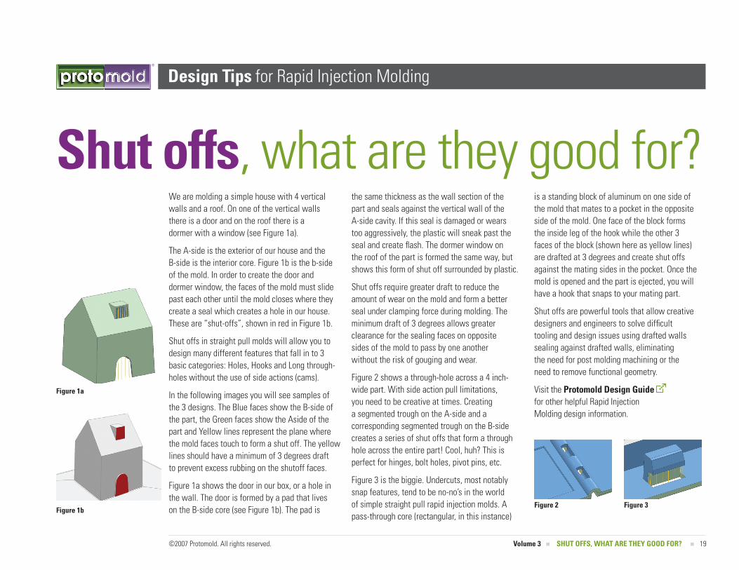
We are molding a simple house with 4 vertical walls and a roof. On one of the vertical walls there is a door and on the roof there is a dormer with a window (see Figure 1a).
The A-side is the exterior of our house and the B-side is the interior core. Figure 1b is the b-side of the mold. In order to create the door and dormer window, the faces of the mold must slide past each other until the mold closes where they create a seal which creates a hole in our house. These are “shut-offs”, shown in red in Figure 1b.
Shut offs in straight pull molds will allow you to design many different features that fall in to 3 basic categories: Holes, Hooks and Long through-holes without the use of side actions (cams).
In the following images you will see samples of the 3 designs. The Blue faces show the B-side of the part, the Green faces show the Aside of the part and Yellow lines represent the plane where the mold faces touch to form a shut off. The yellow lines should have a minimum of 3 degrees draft to prevent excess rubbing on the shutoff faces.
Figure 1a shows the door in our box, or a hole in the wall. The door is formed by a pad that lives on the B-side core (see Figure 1b). The pad is
the same thickness as the wall section of the part and seals against the vertical wall of the A-side cavity. If this seal is damaged or wears too aggressively, the plastic will sneak past the seal and create flash. The dormer window on the roof of the part is formed the same way, but shows this form of shut off surrounded by plastic.
Shut offs require greater draft to reduce the amount of wear on the mold and form a better seal under clamping force during molding. The minimum draft of 3 degrees allows greater clearance for the sealing faces on opposite sides of the mold to pass by one another without the risk of gouging and wear.
Figure � shows a through-hole across a 4 inch-wide part. With side action pull limitations, you need to be creative at times. Creating a segmented trough on the A-side and a corresponding segmented trough on the B-side creates a series of shut offs that form a through hole across the entire part! Cool, huh? This is perfect for hinges, bolt holes, pivot pins, etc.
Figure 3 is the biggie. Undercuts, most notably snap features, tend to be no-no’s in the world of simple straight pull rapid injection molds. A pass-through core (rectangular, in this instance)
is a standing block of aluminum on one side of the mold that mates to a pocket in the opposite side of the mold. One face of the block forms the inside leg of the hook while the other 3 faces of the block (shown here as yellow lines) are drafted at 3 degrees and create shut offs against the mating sides in the pocket. Once the mold is opened and the part is ejected, you will have a hook that snaps to your mating part.
Shut offs are powerful tools that allow creative designers and engineers to solve difficult tooling and design issues using drafted walls sealing against drafted walls, eliminating the need for post molding machining or the need to remove functional geometry.
Visit the Protomold Design guide for other helpful Rapid Injection Molding design information.
©�007 Protomold. All rights reserved. Volume 3 n ShUT oFFS, whAT ARE ThEy gooD FoR? n
Shut offs, what are they good for?
Figure 1a
Figure 1bFigure 2 Figure 3