no slide titleeng.staff.alexu.edu.eg/~mmorsy/courses/undergraduate/ee_principles_and... ·...
TRANSCRIPT

MALVINO & BATES
SEVENTH EDITION
Electronic
PRINCIPLES
Copyright © The McGraw-Hill Companies, Inc. Permission required for reproduction or display.
Transistor Biasing
Chapter 8

Copyright © The McGraw-Hill Companies, Inc. Permission required for reproduction or display.
Topics Covered in Chapter 8
• Voltage-divider bias
• Accurate VDB analysis
• VDB load line and Q point
• Two-supply emitter bias
• Other types of bias
• Troubleshooting
• PNP transistors

Copyright © The McGraw-Hill Companies, Inc. Permission required for reproduction or display.
Voltage divider bias
• Base circuit contains a voltage divider
• Most widely used
• Known as VDB

Copyright © The McGraw-Hill Companies, Inc. Permission required for reproduction or display.
+VCC
RC
RE
R1
R2
Voltage divider bias circuit
R1 and R2 form
a voltage divider

Copyright © The McGraw-Hill Companies, Inc. Permission required for reproduction or display.
+VCC
R1
R2
+VBB
Divider analysis:
VBB = R2
R1 + R2 VCC
ASSUMPTION: The base
current is normally much
smaller than the divider current.

Copyright © The McGraw-Hill Companies, Inc. Permission required for reproduction or display.
IE = VBB - VBE
RE
VC = VCC - ICRC
VCE = VC - VE
IC @ IE
+VCC
RC
RE VBB
To complete the analysis:
Now the circuit can be viewed this way:

Copyright © The McGraw-Hill Companies, Inc. Permission required for reproduction or display.
The six-step process
1. Calculate the base voltage using the
voltage divider equation.
2. Subtract 0.7 V to get the emitter voltage.
3. Divide by emitter resistance to get the
emitter current.
4. Determine the drop across the collector
resistor.

Copyright © The McGraw-Hill Companies, Inc. Permission required for reproduction or display.
The six-step process
(Continued)
5. Calculate the collector voltage by
subtracting the voltage across the
collector resistor from VCC.
6. Calculate the collector-emitter voltage by
subtracting the emitter voltage from the
collector voltage.
Copyright © The McGraw-Hill Companies, Inc. Permission required for reproduction or display.
VDB analysis
• The base current must be much smaller
than current through the divider
• With the base voltage constant, the
circuit produces a stable Q point under
varying operational conditions

Copyright © The McGraw-Hill Companies, Inc. Permission required for reproduction or display.
+VCC
RC
RE
R1
R2
Is the divider a stiff source?
Find the Thevenin
resistance.
RTH = R1 R2

Copyright © The McGraw-Hill Companies, Inc. Permission required for reproduction or display.
+VCC
RC
RE VBB
RTH
A Thevenin model of the bias circuit:

Copyright © The McGraw-Hill Companies, Inc. Permission required for reproduction or display.
+VCC
RC
RE
The 100:1 rule applied to the bias circuit:
RIN
VBB
RTH
RTH < 0.01 RIN
When this rule is met,
the divider is stiff.

Copyright © The McGraw-Hill Companies, Inc. Permission required for reproduction or display.
Firm voltage divider
• Used because divider resistors (e.g. R1
and R2) in a stiff design would be too
small
• The collector current will be about 10%
lower than the stiff value

Copyright © The McGraw-Hill Companies, Inc. Permission required for reproduction or display.
+VCC
RC
RE
R1
R2
Sometimes a firm divider is chosen.
R1 R2 < 0.1 bdcRE
A closer approximation:
IE = VBB - VBE
RE + bdc
R1 R2

Copyright © The McGraw-Hill Companies, Inc. Permission required for reproduction or display.
VDB load line and Q point
• VDB is derived from emitter bias
• The Q point is immune to changes in
current gain
• The Q point is moved by varying the
emitter resistor

Copyright © The McGraw-Hill Companies, Inc. Permission required for reproduction or display.
Two-supply stiff emitter bias:
10 V 3.6 kW
2.7 kW 1 kW
2 V
Assume 0 V
IE = VEE - 0.7 V
RE
IE = 2 V - 0.7 V
1 kW = 1.3 mA

Copyright © The McGraw-Hill Companies, Inc. Permission required for reproduction or display.
10 V 3.6 kW
2.7 kW 1 kW
2 V
VC = 10 V - (1.3 mA)(3.6 kW) = 5.32 V
VCE = 5.32 V - (-0.7 V) = 6.02 V
Find the voltages:

Copyright © The McGraw-Hill Companies, Inc. Permission required for reproduction or display.
+VCC
RC RB
Base bias:
•The least predictable
•Q point moves with replacement
•Q point moves with temperature
•Not practical

Copyright © The McGraw-Hill Companies, Inc. Permission required for reproduction or display.
+VCC
RC
RE
RB Emitter-feedback bias:
•Better than base bias
•Q point still moves
•Not popular

Copyright © The McGraw-Hill Companies, Inc. Permission required for reproduction or display.
+VCC
RC RB
Collector-feedback bias:
•Better than emitter-feedback bias
•Q point still moves
•Some applications because of circuit
simplicity

Copyright © The McGraw-Hill Companies, Inc. Permission required for reproduction or display.
+VCC
RC RB
RE
Collector- and emitter
-feedback bias:
•Better than emitter-feedback bias
•Not as good as voltage-divider bias
•Limited application

Copyright © The McGraw-Hill Companies, Inc. Permission required for reproduction or display.
Two-supply emitter bias:
•Very stable
•Requires 2 supplies
Note: Also called TSEB
Copyright © The McGraw-Hill Companies, Inc. Permission required for reproduction or display.
+VCC
RC
RE
R1
R2
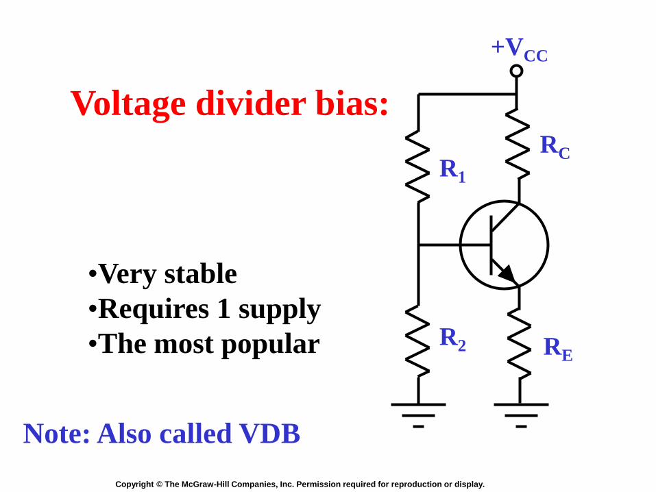
Voltage divider bias:
•Very stable
•Requires 1 supply
•The most popular
Note: Also called VDB

Copyright © The McGraw-Hill Companies, Inc. Permission required for reproduction or display.
Troubleshooting
• Voltage measurements
• Use 10 MΩ input voltmeter
• Troubles include:
ü Opens
ü Shorts
ü Faulty transistors
Copyright © The McGraw-Hill Companies, Inc. Permission required for reproduction or display.
PNP transistor
• The base is n-type material
• The collector and emitter are p-type
material
• The emitter arrow points in
• Can be used with a negative power
supply

Copyright © The McGraw-Hill Companies, Inc. Permission required for reproduction or display.
Electron flow Conventional flow
IC IB
IE
IC IB
IE
PNP transistor symbol
and current flow

Copyright © The McGraw-Hill Companies, Inc. Permission required for reproduction or display.
-VCC
RC
RE
R1
R2
PNP Biasing with a
negative supply

Copyright © The McGraw-Hill Companies, Inc. Permission required for reproduction or display.
+VEE
RE
RC
R2
R1
PNP Biasing with a
positive supply