no. 678 digital communicator - fire alarm...
TRANSCRIPT
No. 678 DIGITAL
COMMUNICATOR
GENERAL INFORMATION:
The 678 is an 8 channel digital communicator that transmits coded messages over ,the telephone system to a digital receiver located at a central monitoring station. Special leased lines are not required. (There is a 9th channel dedicated to user test and optional low ba=y reporting.)
To accommodate various receivers, the 678 can transmit in three formats: I) Ademco (and Silent Knight), 2) Ademco High Speed or 3) Sescoa/Franklin/DCI.
The 678 consi sts of a printed ci rcuit board chassis Bnd cover that may be in&a I led in any suitable enclosure, such as the Nos. 204 or 205 Cabinets, or the lower section of a No: 1023 or 1024 Alarm Processing Center’s cabinet. (Note: The upper section of a No. 1023 or 1024’s cabinet may be used as well, if the 678 is mounted behind or in lieu of the APC’s normal control chassis.)
The 678 may be powered from a 6 or 12V. DC, filtered rechargeable, source [such as (for 6V): Ademco Nos. 492, 493-j. Caution: The Nos. 89 and 89-12 Energy Packs may not be used, nor may sources containing Ni-Cad batteries such as the Nos. 96, 97, 497. A comnon power supply from a control panel can be used, even with bells connected to the control (No. 1026 or 1028 series Alarm Processing Centers may not be used, as they conta i n ‘N i-Cad standby batteries 1.
The 678 may be triggered by: I) Application (or removal) of 6-l2V. DC supplied from any alarm control (or other DC source), 2) Dry contact closure, 3) Dry contact opening.
The 678 is easily programmed by the insertion of a PROM (Programmable ReadgnlY &emorYj Chip, such as the No. 691. PROM Chips can be programmed bv Ademco or (with the No. 690 Programmer) by the i nstal ler.
The 678 has built-in line seizure and telephone line surge arrestors. Line seizure automatically disconnects all telephones in ttie premises on the same line with the communicator whenever the 678 is activated, to insure transmission without interruption. Surge arrestors help protect the 678 from’voltage surges on the telephone line.
The 678 is compatible with the Ademco family of ancillary communicator accessories, including the following:
Cat. No. Description
620’ Di rect Connect Cord 659 Line Fault Monitor 664 Digital Communicator Tester 674 Select-A-Line (two line select module) 675 Ground Start Module 676/677 Listen-in System 684 Remote Command Tone Responder 688 Opening/Closing Switching Module 689 AC Power/Telephone Line Fault Monitor
826 I Remote Buzzer 179
173
www.PDF-Zoo.com
OPERATION:
When a channel is activated; transm as follows:
.
iss ion to the central monitoring station occurs ,
I. After the normal 150 millisecond response time (or I6 seconds delay if so programmed) the 678 executes line seizure and forces .a 1.6 second hang-up to insure a disconnect if an outqoinq call was beina made. @: The 678 has a built-in ACTIVATION LED which lights wh&ever the unit is activated.
2. Next, the 678 checks for dial tone. To shorten the time required for contacting the central monitoring station, the 678 can sense internal dial tone as well as external (telephone company) dial tone’.
3. If dial tone is detected, the 678 immediately and automatically dials the preprogrammed telephone number, which can consist of up to 4 access digits and up to I2 digits in the main (telephone company) number. Two telephone numbers can be programmed and dialed as explained in PROGRAMMING OPTiONS. Furthermore, the 678 can be programmed to dial “touch tone” in I ieu of the slower “pulse dial” method.
The probability of immediate dial tone detection is high, but ff a dial tone is not detected within II seconds, (.30 seconds, if so programmed), the 678 wi India I anyway, on the assumption that the connection may be good even though the dial’ tone is not clear.
4. W.hen connection is-made with the central monitoring receiver, a “handshake” tone (acknowledgment) is sent over the telephone lines by the receiver to the 678. This “handshake” confirms, to the 678, that connection has been camp leted to the r’ece i ver.
I f “handshake” is not received within 30 seconds (60 seconds if so programmed), the communicator will disconnect itself from the telephone line. After waiting long enough (approximately 30 seconds) to disconnect any outgoing or incoming calls which might interfere with diali-ng (“anti-jam” which only works in “called party’ control exchanges), the 678 will reconnect to the telephone I i ne, and again seize the line, check for dial tone and dial as described in Steps I, 2 and 3.
If necessary the 678 wi I I make up to a total of 8 attempts* (or “Unl imited Attempts”, if so programmed) to reach the central monitoring station via primary and/or secondary programmed telephone numbers. See PROGRAMMING OPTIONS.
5. Upon receipt of the “handshake” (acknowledgment) tone, the 678 will start transmitting its message(s), each consisting of a subscriber identification number and a I digit alarm code corresponding to the number of the channel that tri ggered.
Since faulty phone lines can distort the numbers, the 678 sends each message up to 4 times while the receiver compares each message with the one before it. As soon as the Receiver detects 2 successive identical messages, it considers the transmission “valid” and sends a “kiss-off” code to the Communicator.
l f more than one channe I has triggered, the triggered channels will report in order of ‘priority (i.e.: low alarm numbers first) unless subsequent channels trigger while one or more channels have commenced transmission. Each channel message must receive “kisgS~ff” before the next is sent.
174
www.PDF-Zoo.com
Example: If Channels 3 and G of Subscriber 1890 go into alarm, the 678 will respond as follows in conjunction with an Ademco 660 (or Silent Knight; SESCOA, Frahkiin or DCI) Receiver:
890 3 890 3 “kiss-off” 890 6 890 6 Final “kiss-sff” (No. 678 hangs up)
Note : Only the last 3 digits of the subscriber identification number will in this case be sent. The full 4 digits will be used in conjunction with an Ademco No. 685 High Speed Receiver (available soon).
If the 678 does not receive the “kiss-off” code(s) by the time it has sent its message(s) four times, it hangs up and dials again. Up to a total of 8 attempts *or “Un I i m i ted Attempts”, if so programmed wi I I be made to reach the central monitoring station via primary and/or secondary programmed telephone numbers. See PROGRAMMING OPTIONS. .
6. In the event that “handshake” or “‘kiss-off” is not received’ the 678 ‘hanqs up and tries agaln. I f necessary, the 678 wi I I make up to a tota I of 8 aTtempts “(or “Un.1 imi ted Attempts” if so programmed) to reach the centra I monitoring station, via primary and/or secondary telephone numbers. If, after these attempts, the 678 has not made contact and received “kiss-off” it will shut down and stop dialing (unless programmed for “Unlimited Attempts”).
The 678 has a built-in KISS-OFF LED which lights upon receipt of”kiss-of-f” and goes out 8 seconds after completion of all transmission to that telephone number.
*If the “Dual Report” option is selected, the 678 will make up to 8 attempts to reach each telephone number.
PROGRAMMING OPTIONS:
The No. 678 may be programmed with a number of opti.ons which affect its method of sensing alarms and reporting to the central monitoring station. Programing is contained in a PROM Chip (No. 691) which can be programmed by Ademco or (with the No. 690 Programmer) by the instaIIer:The PROM Chip is inserted in the 678 during installation.
See Diagram 3 for a reproduction of the form used in programming the PROM chip. It- may be used to record the PROM programming used for the actual installation as well as a guide for requesting a differently programmed PROM.
Some of these options affect the unit as a whole, while others affect only the desired channel. The options which affect the units as a whole are:
&tern Programming Options:
I. Low Battery Trigger and Report: Initiates a call to the ten station and sends Code 8 when the rechargeable power source 5 volts (IOV for a l2V rechargeable source). This report wi repeated during later alann transmissions.
181
tral’monitoring drops be I ow
I I not be -.
175
www.PDF-Zoo.com
2.
3.
4.
5.
6.
7’.
8.
Dua I Report: Reports all information to the second, telephone number after receiving kissoff from the receiver at the primary number. In the event that 8 attempts are made, but no “kiss-off” is received from the primary number, the No. 678 will then make 8 more’attempts to report to the secondary number. c-3 :, ,: Note: When Dua I Report is’ used, xbe programmed.
Unlimited Attempts (System Option 7)should
Alternate by Pairs: The dialer will’attempt to fall the primary number twice, then, if “kiss-off” has not been received, it will make two attempts to reach the receiver at the secondary number. It w i I I a I ternate by pai rs of ca I Is unti I a tota I of 8 attempts have been camp leted, or ” ki s&off” is received.
Extended Acknowledge Wait: Doubles the acknowledgment wait period from 30 seconds to 60 seconds. Helpful on phone networks with long switching time.
Extended Dial Tone Wait: Triples the dial tone waiting period from II seconds to 30 seconds. IJseful in slow dial tone areas.
Touch Tone Dia I : Instructs the communicator to dial touch tone instead of the slower pulse dial method.
Unlimited Attempts: Causes the 678 to continue making attempts to reach the receiver until “kiss-off” 1s received, rather than ceasing after 8 attempts. Note: Unlimited Attempts should not be programmed when Dual Report (System won 2) is used.
SESCOA: Causes the No. 678 to look for the SESCOA/Franklin/DCI acknowledge and acknowledge hold signals and to report in SESCOA format. If this option :r--)
is not selected, the No. 678 will respond in the Ademco standard format. ‘,.
For,Ademco hi-speed format see instructions accompanying the No. 685 Receiver.
Channel Programming Options:
In addition to the system options, there are a number of options which can be selected and which affect only those channels which the user desires. These are:
I. Long De lay Channels: Any number of channels may be programmed for a I6 second delay. Thus, the.nonal 150 millisec response time can be extended to 16 seconds to minimize false triggering due to transients.
2. Open/Close Channels: Channels selected as Open/Close Channels will report when the triggering \;oItage appears as well as when the input voltage is removed.
In order to transmit opening and closing rounds, the 678 must receive signals when the control panel is armed and disarmed. These signals are available directly from the No. 1023 Al.arm Processing Center or Nos. 1022, 1024, 1026 and 1028 Alarm Processing.Centers when used with the No. 688 Opening/Closing Switching Module. The signal may be applied to the 678 when the control i s armed and removed when the contra I is disarmed, or vice versa.
With the standard Ademco or SESCOA format, an Open/Close Channel will report the subscriber identification (the 3 last digits of the 4 digit identification code contained in the PROM) followed by the number of the channel when an input is applied to the channel.
182
176
c-3 . . ’
www.PDF-Zoo.com
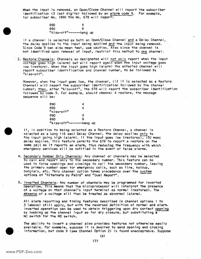
When the input is removed, an Open/Close Channel will report the subscriber identification (3 last digits) followed by an alarm code 9. For example, for subscriber No. 1890 the No. 678 will report:
890 9 890 9 “Ki ss-off “------hang up
If a channel is selected as both an Open/Close Channel and a Delay Channel, the delay applies to the input being applied and the in- being removed. Since Code?9 can also mean test, use caution.Tso since the channel is not identified upon removal of input, restrict’this method to one channel.
3. Restore,ChanneIs: Channels so designated will not only report when the input voltage goes high (alarm) but will report again when the input voltage goes low (restore). When the input goes high (alarm) the affected channel .wi II report subscriber identification and channel number, to be followed by “kiss-off”.
However, when the input goes low, the channel, (if it is selected as a Restore Channel) will report the subscriber identification followed by the channel number; then, after “kiss-off”, the 678 will report the subscriber identification followed by code 9. For example, should channel 4 restore, the message sequence wi I I be:
890 4 890 4 “kiss-off” 890 9 890 9 “kiss-off”------hang up
If, in addition to being selected as a Restore Channel, a channel is selected as a Long (I6 set) Delay Channel, the.delay applies only to the input going high (alarm). If the input goes low (restores), 150 msec de lay app I ies. This feature permits the 678 to report a restore on the same call. as it reports an alarm, thus reducing the frequency .with which . . .‘a, i,: emergency services will be notified in the event of false alarms.
4. Secondary Number Only Channels: Any channel or channels may be’selected to call and report only to the secondary number. This feature can be used to force openings and closings to call the secondary number, leaving the primary number open for emergency cal Is, such as fire, holdup, burglary, etc. This channel option takes precedence over the system optlons of “Alternate by Pal&’ and “Dual Report”.
5. Inverted Channels: Any number of chanhels may be programmed for inverted operation. This means that the mi croprocessor wi I I interpret the presence of a voltage on that channel’s input terminal as normal (restored). The absence of a voltage will then be treated ,as abnormal (alarm).
All alarm reporting and timing features described in channel options I to 3 (above) still apply, but with the reversed definition of normal and alarm. Inverted operation can be used to obtain triggering upon dry contact opening by hooking up the channel input as for dry closure, but substituting a NC switch for the NO switch.
The ability to invert a channel also provides features not otherwise easily
a
available. For example, suppose it is desired to send opening and closing information, but code 9 (see Channel Option 2) is found unacceptable. Suppose
183
177
www.PDF-Zoo.com
further.that a code 4 is wanted for closing (input going low) and code 5 for opening (. input going h’igh) . Simply tie the inputs of channels 4 and 5 together and then to the control unit. Program channel 4 (input going low) for inverted operation. In this case DO N’OT program either channel 4 or 5 for Open/Close or for Restore. Note: I6 set delay, if selected, will apply when signal is removed from thexerted channel.
Channels 4 and/or 5 or any other combination used this way may be programmed for Long Delay or Second Number Only (as desired).
The “Kiss-off” (Ring-Back) Feature is an important tool when transmitting test or opening/closing si,gnals. Once “kiss-off” is received, the built-in LED will light and stay on for 8 seconds. By remoti ng an LED or buzzer
1 (Ademco No. 8261) at a convenient location, the customer is advised of a successful transmission to the receiver.
INSTALLATION PROCEDURE:
Mounting:
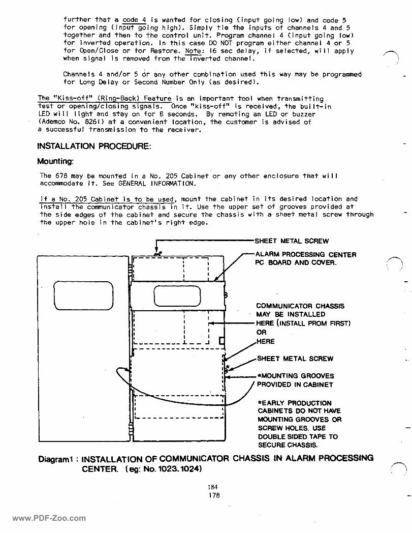
The 678 may be mounted in a No. 205 Cabinet or any other enclosure that will accommodate it. See GENERAL INFORMATION.
If a No. 205 Cabinet is to be used, mount the cabinet in its desired location and install the communicator chassis in it. Use the upper set of grooves provided at the side edges of the cabinet and secure the chassis with a sheet metal screw through the upper hole in the cabinet’s right edge.
I SHEET METAL SCREW t&
ur -------r--1 I I 1
I
I I .I_ I I
I I! i IL
.I r I -------- -- A L
I!
----------------a
i
1 I I 4
I I I I L--------------d
/-
ALARM PROCESSING CENTER PC BOARD AND COVER. n :’
COMMUNICATOR CHASSIS MAY BE lNSTALLED
- HERE (INSTALL PROM FIRST) OR HERE
SHEET METAL SCREW
,.-*MOUNTING GROOVES
/ PROVIDED IN CABINET
*EARLY PRODUCTION CABINETS DO NOT HAVE MOUNTING GROOVES OR SCREW HOLES. USE -
DOUBLE SIDED TAPE TO SECURE CHASSIS.
Diagram1 : INSTALLATION OF COMMUNICATOR CHASSIS IN ALARM PROCESSING CENTER. ( eg: No. 1023,1024)
184 178
www.PDF-Zoo.com
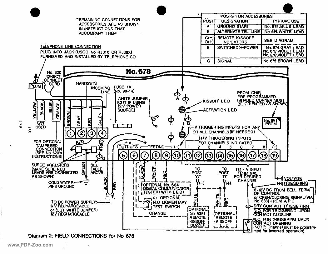
.- POSTS FOR ACCESSORIES
POST OESIGNATION I TYPICAL USE A GROUND START 1 No. 675:BLUE LEAD B ALTERNATE TEL. LINE No. 674: WHITE LEAD
;;-; REMOTE KISSOFF INDICATORS SEE DIAGRAM
E SWITCHED(+)PO No. 674:GRAY LEAD No. 675:YIOLET LEAD No. 676:V10LET LEAD
G SIGNAL NO. 675: BROWN LEAD J
*
I *REMAINING CONNECTIONS FOR
ACCESSORIES ARE AS SHOWN IN INSTRUCTIONS THAT ACCOMPANY THEM
TELEPHONE LINE CONNECTION PLUG INTO JACK (USOC No. RJ31X OR RJ36X) FURNISHED AN0 INSTALLED BY TELEPHONE CO.
HANDSETS
PROM CHIP, PRE-PROGRAMMED.
KfSSOFF LE D
-)V TRIGGERING INPUTS FOR ANY OR ALL CHANNELS(IF NEEDED) WI
SOURCE)
FOR OPTlotjAL TAMPERED CONNECTION (SEE NO. 626s
INSTRUCTIONS)
SURGE ARREsiG (MAKE SURE RE LEADS ARE COh AS SHOWN)
TO +v’lNPUT TERMINAL
FORD:;: -- I
A A L /(+)ITRIGGERtNG 1 y” L(-)\ VOLTAGE _
1 ~~D~O-F-ROM BELL TERM.71
I
OF CONTROL or OPEN/CLOSING SIGNAL (VIA No. 666) FROM A P C 4
COLD WATER -7 PIPE GROUND
TO DC POWER SUPPLY:- 6 V RECHARGEABLE or (CUT WHITE. JUMPER) 12V RECHARGEABLE
DRY CONTACT TRIGGERING FOR TRIGGERING UPON
I L - - - -- --
TACT CLOSURE
---
!!: ! rk N.C. FOR TRIGGERING UPON CT OPENING
ITE: Channel must be program- 01 med for inverted operation)
Diagram 2: FIELD CONNECTIONS for No. 678
/ I www.PDF-Zoo.com
I.
2.
3.
4.
5.
6.
7.
8.
9.
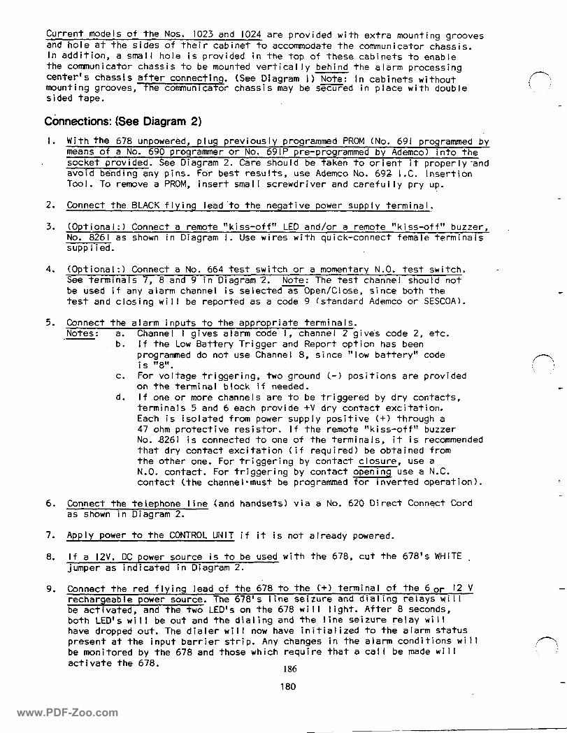
Current models of the Nos. 1023 and 1024 are provided with extra mounting grooves and hole at the sides of their cabinet to accommodate the communicator chassis. In addition, a small hole is provided in the top of these cabinets to enable the communicator chassis to be mounted vertically behind the alarm processing center’s chassis after connecting. (See Diagram 1) Note: In cabinets without mounting grooves, the communicator chassis may be sZZi.YFed in place with double sided tape.
Cbnnections: (See Diagram 2)
With the 678 unpowered, plug previously D
means of a No. 690 oroarammer or No. 69 rogrammed PROM (No. 691 programmed by
socket provided. See Diagram 2. 116 pre-programmed by Ademco) into the
Care shou Id be taken to orient it properly -and avoid bending any pins. For best results, use Ademco No. 692 I.C. Insertion Tool. To remOve a PROM, insert smal I screwdriver and careful ly pry up.
Connect the BLACK flying lead ‘to the neqative power supply terminal.
(Optional:) Connect a remote “kiss-off” LED and/or a remote “kiss-off” buzzer, No. 8261 as shown in Diagram I. Use wires with quick-connect female terminals supp I i ed.
(Optional:) Connect a No. 664 test switch or a momentary N.O. test switch. - See terminals 7, 8 and 9 in Diagram 2. Note: The test channel should not be used if any alarm channel is selected as Open/Close, since both the test and closing will be reported as a code 9 (standard Ademco or SESCOA).
Connect the alarm inputs to the appropriate termina Is. Notes: a. Channel I gives alarm code I, channel 2 gives code 2, etc.
b. If the Low Battery Trigger and Report option has been programmed do not use Channe I 8, si nce ” low battery” code is 8. 11 1,
C. For voltage triggering, two ground (.-I positions are provided on the terminal block if needed.
d. If one or more channels are to be tr‘iggered by dry contacts, terminals 5 and 6 each provide +V dry contact excitation. Each is isolated from power supply positive (+I through a 47 ohm protective resistor. If the remote “kiss-off” buzzer No. 8261 is connected to one of the terminals, it is recommended that dry contact excitation (if required) be obtained from the other one. For triggering by contact closure, use a N.O. contact. For triggering by contact opening use a N.C. contact (the channel-must be programmed for inverted operation).
Connect the teI.ephone line <and handsets) via a No. 620 Direct Connect Cord as shown i n Diagram 2.
Apply power to the CONTROL UNIT if it is not already powered.
If a l2V. DC power source is to be used with the 678, cut the 678’s WHITE . jumper as indicated in Diagram 2.
Connect the red flying lead of the 678 to the (+I terminal of the 6 or I2 V rechargeable power source. The 678’s line seizure and dialing relays will be activated, and the two LED’s on the 678 will light. After 8 seconds, both LED’s will be out and the dialing and the line seizure relay will have dropped out. The dialer will now have initialized to the alarm status present at the input barrier strip. Any changes in the alarm conditions will be monitored by the 678 and those which require that a call be made will activate the 678.
186
180
-
www.PDF-Zoo.com
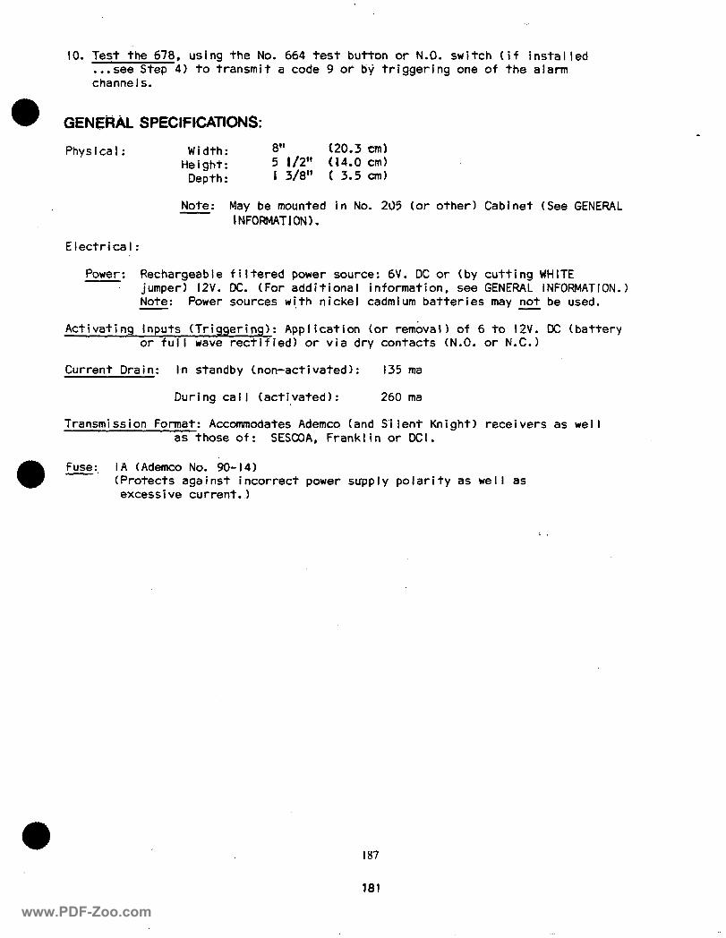
IO. Test the 678, using the No. 664 test button or N.O. switch (if installed . ..see Step 4) to transmit a code 9 or by triggering one of the alarm channels.
GENE#k SPECIFlCATIoN$:
Physical: Width: 8” (20.3 cm) Height: 5 l/2” (14.0 cm)
Depth : I 3/8” ( 3.5 cm)
Note : May be mounted in No. 205 (or other) Cab I NFORMAT 1 ON 1.
Electrical:
i net (See GENERAL
Power: Rechargeable filtered power source: 6V. DC or (by cutting WHITE jumper) l2V. DC. (For additional information, see GENERAL INFORMATION.) iiote: Power sources with nickel cadmium batteries may not be used.
Activating Inputs (Triggering): Application (or removal) of 6 to or full wave rectified) or via dry contacts (N.0. or N
2V. DC (battery c-1
Current Dra i n: I-n standby (non-activated): 135 ma
During call (activated): 260 ma
Transmission Format: Accommodates Ademco (and S’ilent Knight) receivers as well as those of: SESCOA, Franklin or DCI.
E:, IA (Ademco No. 90-14) (Protects against incorrect power supply polarity as well as excessive current..)
187
181
www.PDF-Zoo.com
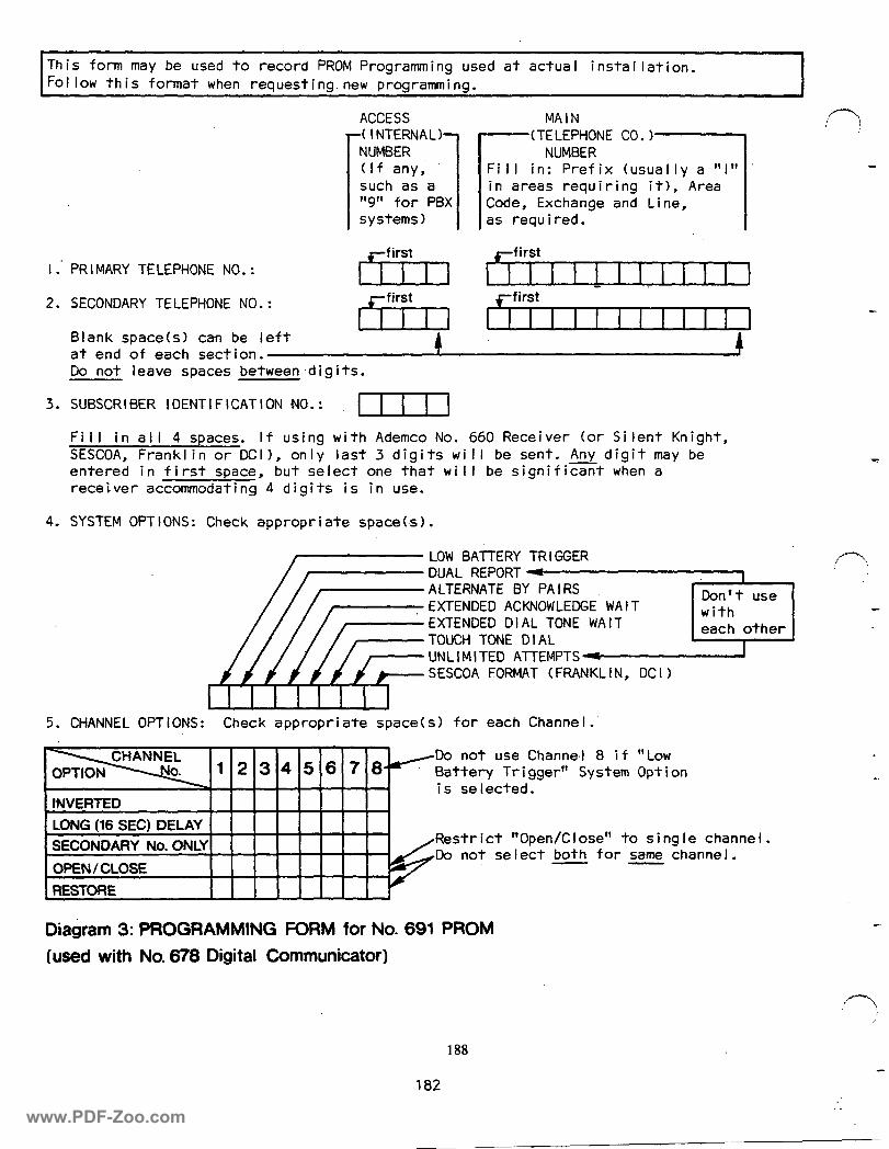
Th is form may be used to record PROM Programming used at actua I i nsta I I at ion. Follow this format when requesting.new programming.
ACCESS MAIN
I : PR I MARY TELEPHONE NO. :
2. SECONDARY TELEPHONE NO.:
Blank space(s) can be left at end of each section. Do not leave spaces between .di g i ts.
3. SUBSCRIBER IDENTIFICATION NO.: I I I I Fill in all 4 spaces. If using with Ademco No. 660 Receiver (or Silent Knight, SESCOA, Franklin or DCII, only last 3 digits will be sent. Any digit may be entered in first space, but select one that will be significant when a receiver accommodating 4 digits is in use.
4. SYSTEM OPTIONS: Check appropriate space(s).
LOW BATTERY TRIGGER
.~~~~
SESCOA FORMAT (FRANKLIN, DCI)
5. CHANNEL OPTIONS: Check appropriate space(s) for each Channel.’
123456780 -Do not use Channe.1 8 i f “Low
Battery Trigger” System Option iS selected.
INVERTED I I I I I I I I LONG (16 SEC) DELi SECONDAR” &In hm
OPEN /CLOSE
, RESTORE
I Restrict “Open/Close” to single Channel.
I I I / -Do not select both for same channel.
Diagram 3: PROGRAMMING FORM for No. 691 PROM
(used with No. 678 Digital Communicator)
188
182
www.PDF-Zoo.com
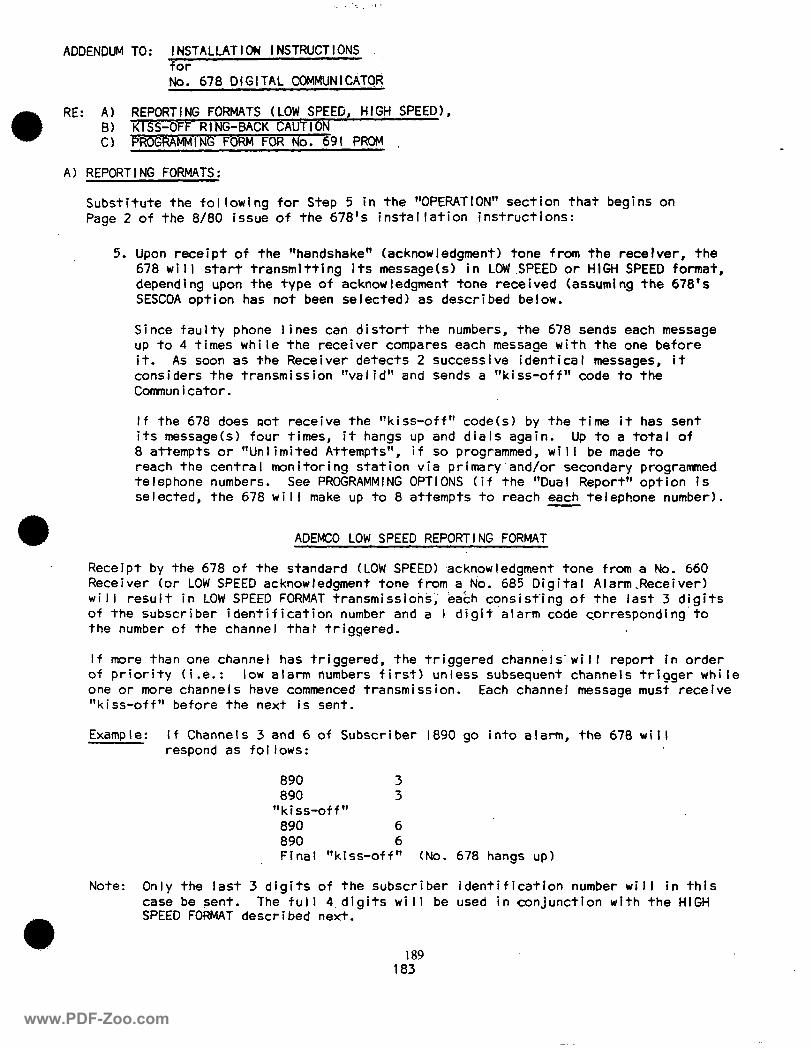
ADDENDUM TO: INSTALLATIOW INSTRUCTIONS for
No. 678 DIGITAL COMMUNICATGR
RE: A) REPORTING FORMATS (LOW SPEED, HIGH SPEED), B) KISS-OFF RtNG-BACK CAUTION Cl P;9l PROM
A) REPORTING FORMATS:
Substitute the following for Step 5 in the “OPERATION” section that begins on Page 2 of the 8/80 issue of the 678’s installation instructions:
5. Upon receipt of the “handshake ” (acknowledgment) tone from the receiver, the 678 wi I I start transmitting its message(s) in LOW SPEED or HIGH SPEED format, depending upon the type of acknowledgment tone received (assuming the 678’s SESCOA option has not been selected) as described below.
Since faulty phone lines can distort the numbers, the 678 sends each message up to 4 times while the receiver compares each message with the one before it. As soon as the Receiver detects 2 successive identical messages, it considers the transmission “valid” and sends a “kiss-off” code to the Communicator.
If the 678 does raot receive the “kiss-off” code(s) by the time it has sent its message(s) four times, it hangs up and dials again. Up to a total of 8 attempts or “Un I i mi ted Attempts”, i f so programmed, wi I I be made to reach the central monitoring station via primary’and/or secondary programed telephone numbers. See PROGRAMMING OPTIONS (if the “Dual Report” option is selected, the 678 will make up to 8 attempts to reach each telephone number).
ADEMCO LOW SPEED REPORTING FORMAT
Receipt by the 678 of the standard (LOW SPEED) .acknowIedgment tone from a No. 660 Receiver (or LOW SPEED acknowledgment tone from a No. 685 Digital Alarm.Receiver) will result in LOW SPEED FORMAT transmissions, each consisting of the last 3 digits of the subscriber identification number and a I digit alarm code corresponding’to the number of the channel that triggered.
If more than one channel has triggered, the triggered channols’wi II report in order of priority (i.e.: low alarm numbers first) unless subsequent channels trigger while one or more channel s have commenced transmission. Each channel message must receive “kiss-off” before the next is sent.
Examp I e: If Channels 3 and 6 of Subscriber 1890 go into alarm, the 678 will respond as follows:
890 3 890 3
“kiss-off” 890 6 890 6 Final “kiss-off” (No. 678 hangs up)
Note : Only the last 3 digits of the subscriber identification number will in this case be sent. The full 4 digits will be used in conjunction with the HIGH SPEED FORMAT described next.
189 183
www.PDF-Zoo.com
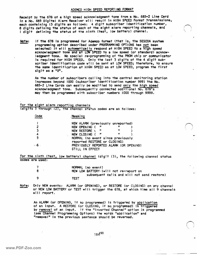
AGEMCO HIGH SPEED REPORTING FORMAT
Receipt by the 678 of a hlgh speed acknowledgment tone from a No. 685-2 Line Card In a No. 685 Glgltal Alarm Receiver will result In HIGH SPEED Format transmissions, each contalnlng I3 dlgits as follows: 4 dlglt subscrlber ldentlficatlon number, 8 dlglts deflnlng the status of each of.the eight alarm reportlng channels, and I dlglt deflnlng the status of the nlnth (test, low battery) channel.
:(---I : ’ . .’
Note: If the 678 Is progranrned for Adamoo format (that Is, the SESCOA system programntng optlon described under PROGRAMMING OPTIONS has not been selected) It will automatically respond at HIGH SPEED to a flh speed acknowledgment tone and at LOW SPEED to a low speed (or standard) acknow- ledgment tone. No special re-programming of the PROM chip or communicator 1s required for HIGH SPEED. Only the last 3 digits of the 4 dfglt sub- scriber I-dentification code will be sent at LOW SPEED; therefore, to ensure the same ldent i f I cat ion at HIGH SPEED as at LOW SPEED, program the f i rst dlgit as a ‘rCl*‘.
As the,number of subscrlbers calling into the central monitoring statlon Increases beyond 1000 Csubscriber identification number 999) the No. 685-Z Line C&ds caneasily be modified to send sthe high speed acknowledgment tone. Subsequently connected addit’onal No. 678 s may then be programmed with subscri her numbers 1000 through 9999.
For the elqht alarm reporting channels (digits 5 through 121, the channel status codes are as follows:
Code
I 2 3 4 5
:.d
Mea’iti ng
NEW ALARM (previously unreported) NEW OPENING ( ” It 1 NEW RESTORE k ” ‘l 1 NEW CLOSING ( ” ‘1 1. NORMAL (no event since previously reported RESTORE or CLOSING) PREV I OUSLY REPORTED ALARt+! (OR OPEN I NG) STI LL IN EFFECT
For the ninth (test, low battery) channel (digit 131, the following channel status codes are used:
7 8
9
NORMAL (no event1 NEW LOW BATTERY. (w i I I not re-report on
subsequent calls and will not send restore) TEST
Note : Only NEW events: ALARM (or OPENING), or RESTORE (or CLOSING) on’any channel or NEW LOW BATTERY or TEST will trl’gger the 678, at which time all 9 channels wi I I report.
in \, ,’
An ALARM (or OPENING, if so programned) is triggered by application of an input. A RESTORE (or CLOSING, if so. programmed) is triggered by renrova I of an input. I f the “I nverted Channel ” opt ion is programmed (see Channel Programming Options) the words ‘lappI ication” and “remova I” 1 n the previous sentence shou I d be reversed.
184”
www.PDF-Zoo.com
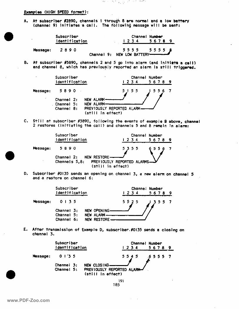
Examples (HI&i SPEED format):
A. At subscriber 12890, channels I through 8 are normal ‘(channel 9) Inltiates,a call. The folIowIng tissage
and a low baitety wtll be sent:
Subscriber ldentlflcatlon
Channel Number I234 5678 9
Message : 2890 Channel 9: NEW 5555 55558 LOW BATTERY
B. At subscriber #5890, channels 2 and. 5 go Into alarm (and Inltiatb a call) and channel 8, which has previously reported an alarm 1s still trtggered.
Subscriber Channel Number ldentlf lcatlon 1234 5678 9
Message: 5890
Channel 2: Channel 5: NEW ALARM Channel 8:
NEW ALARM-2 7 7
PREVIOUSLY REPORTED ALARM (still In effect)
C. Still at subscriber #5890, following the events of example D above, channel 2 restores (initiating the call) and channels 5 and 8 remain In alarm:
Subscriber Channel Number Identification 1234 5678 9
Message : 5890 5355
Channel 2: NEW RESTORE f Channels 5,8: PREVIOUSLY REPORTED ALARMS
(sti.11 In effect)
0. Subscriber 80135 sends an opening on channel 3, a new alarm on channel 5 and a restore on channel 6:
Subscriber ldentlf ication
Message : 0135
Channel 3: NEW Channel 5: NEW Channel 6: NEW
Channe I Number 1234 5678 9
OPENlNG’i’ 5 fy 5 5 7
.E. After transmission of Example D, subscrIber.#Ol35 sends a closing on channel 3.
Subscrlber Channel Number ldentif icatlon 1234 5678 9
Mesziage : 0 I’3 5 Channel 3: NEW CLOSING/ ’ Channel 5: PREVIOUSLY
5545 J 5 5 5 REPORTED ALA
(still in effect)
191 185
www.PDF-Zoo.com
The sending of individual channel status in all HIGH SPEED messages eliminates the ambiguities present in the LOW SPEED format between channel 8 (code 8 in LOW SPEED) and low battery (also code 8 in LOW SPEED). In HIGH SPEED, low battery is reported as a channel 9 status, thus freeing use of channel 8 for alarm reporting (its use in LOW SPEED having been precluded when I’ow battery reporting was selected). .I- .:
Similarly, OPEN/CLOSE programming is restricted to a single channel when standard LOW SPEED Ademco (or SESCOA) format is used (to avoid confusing code 9 “close” with code 9 “test”).~ When HIGH SPEED format is used, however, this restriction does not apply since each channel’s status is sent individually.
The time from detection, by the No. 685, of a call from the communicator, through transmission of two successive I3 digit messages to kiss-off, is lass than 5 seconds[corresponding time for LOW SPEED format would be I5 seconds or more, depending upon the number of channels or type of messages (closing report, for example) to be sent].
CAUT I ON: A No. 685 Digital Alarm Receiver, when equipped with a No. 685-2 Line Card for. Ademco High/Low Speed Format, has the capabi I ity of sending either high or low speed acknowledge signals when called; therefore, it is possible (withTertain telephone line problems) for a No. 678 to reply to a receiver in either HIGH or LOW SPEED format. It is recommend.ed that when the number of subscribers zone telco rotary exceeds 999, the high/low speed line cards be - converted to high speed only by cutting the appropriate jumper on the No. 685-2’s circuit board (see the No. 685’s installation instructions).
SESCOA REPORTING FORMAT
When this option is selected (see PROGRAMMING OPT!ONS section) the 678 will respond to SESCOA/Franklin/GCI acknowledge and acknowledge-hold signals in SESCOA format. Ademco HIGH SPEED format response is not possible when the SESCOA format has been se I ected.
B) KISS-OFF RING-BACK CAUTION:
Add the following to the paragraph on Page 6 of the instructions that describes the Kiss-off Ri%g’-back Feature:
Caution: Discretion is advised if a remote buzzer (or other audible device) is used in conjunction ‘with a communicator that has a si lent emergency a I arm connected to ‘one of its channels, as the buzzer will sound after such an alarm is sent.
C) PROGRAMMING FORM FOR No. 691 PROM:
Make the following changes to the programming form shown in Diagram 5 on Page IO of the instructions:
Step 3: At the end of this step’s instructions, add: (such as a No. 685).
Step 5: Change the,note pointing to channel 8 to read: Do not use channel, 8 if “Low Battery Trigger ” System Option is selected unless HIGH SPEED reporting format is to be used.
Change the first note Restrict “Open/C I ose” format is used.
186
pointing to the OPEN/CLOSE option to read: to single channel unless HIGH SPEED reporting
ALARM EVII+‘ll~Ui~lURlNG CO. 165 Eily,Way, Syosset, New York 1179l
rl
P4967XX fail Cowright 0 lsll PllTWAY CORPORATION
www.PDF-Zoo.com
ADDENDUM TO: INSTALLATION INSTRUCTIONS
No. 678 DIGITAL COWUNICATOR
RE: .IMPROVEMENTS IN LATE PRDDUCTION
The following improvements have been incorporated In current production of the No. 678 Digital Cornnunicator:
I. Reduced current drain:
Standby: 70 ma Activated: 200 ma
2. Can be powered from UNFILTERED, full wave rectified 6V.DC source, . providing that there is no power transfer relay in source (trans-
fer must be accomplished without interruption). Note; 12V. DC power if used, must still be from rechargeable and filtered source .
Triggering may be accomplished by application or removal of 6 to l2V. DC (battery or filtered ful I wave rectified) or via dry contact opening or closure.
Accordingly, the following changes should be made in the accompanying copy of the No. 678’s installation instructions:
A.
B.
Under GENERAL INFORMATION, substitute the following for the fourth and fifth paragraphs:
The No. 678 may be powered from an unfiltered full wave rectified 6V. DC (as described in GENERAL SPECIFICATIONS) or filtered l2V. DC rechargeable source . Caution: The Nos. 89 and 89-12 Energy Packs may m be used, nor may sources containing Ni-Cad batteries (such as the Nos. 96, 97 or 497) that cannot supply at least 70 ma continuously. A canon power supply from a control panel can be used, even with bells connected to the control (No. 1026 or 1028 Series Alarm Processing Centers may not be used as they contain Ni-Cad batteries such as those precluded above).
The No. 678 may be triggered by II Application (or removal) of 6-l2V. DC (battery or filtered full wave rectified) from an alarm control or . . other source, 2) Dry contact closure, 3) Dry contact opening. The 678 may not be triggered from an unfiltered rectified source.
Under GENERAL SPECIFICATIONS, change the Power, Activatino Inputs (Trig- gering) and Current Drain paragraphs to read as follows:
Power: 6V. DC, full wave rectified source. May be unfiltered, providing that there is no power transfer relay in the source (transfer must be accomplished by the source without interruption).
or
l2V. DC rechargeable filtered power source (WHITE jumper must be cut).
Power sources with nickel cadmium batteries may not be used, unless they can provide at least 70 ma continuously. For additional information see GENERAL INFDRMATION.
Activating Inputs (Triggering): Application (or removal) of 6 to l2V. DC (battery or filtered full wave rectified) or via dry contacts (N.O. or N.C.).
Current Drain: Standby (non-activated): 70 me During call (activated): 200 ma
P8259 Y82 ‘187
www.PDF-Zoo.com