nnfm 117 - feasibility of hybrid rans-les modeling of...
TRANSCRIPT

Feasibility of Hybrid RANS-LES Modeling ofShock/Boundary-Layer Interaction in a Duct
Sebastian Arvidson, Shia-Hui Peng, and Lars Davidson
Abstract. A shock induced boundary-layer separation (SBLI) occurring in a ductat M = 1.4 has been analyzed using hybrid RANS-LES methods. The shock waveinteracts with the turbulent wall boundary layers and triggers flow separation in theduct corners. The main purpose of the present work is to highlight the difficultiesin modeling SBLI, particularly, when hybrid RANS-LES models are used. Resultscomputed using different turbulence models are presented and discussed in com-parison with available experimental data. Based on a number of simulations, someissues are addressed and some critical remarks are provided for potential improve-ments using turbulence-resolving modeling approaches in future work.
1 Introduction
Shock/boundary-layer interaction (SBLI) is a common flow phenomenon that re-quires special attention in designing aerial vehicles at trans- and supersonic speeds.Flows passing propelling nozzles, air inlets and wings at transonic and supersonicspeeds are, among others, typical examples where shock/boundary-layer interac-tion may occur. SBLI often leads to extensive pressure fluctuations and turbulentboundary-layer separation. Arising in propelling nozzles or in air inlets, SBLI can
Sebastian Arvidson · Shia-Hui Peng · Lars DavidsonDept. of Applied Mechanics, Chalmers University of Technology,SE-41296 Gothenburg, Swedene-mail: sebastian.arvidson,peng,[email protected]
Sebastian ArvidsonSaab Aeronautics, SE-58188 Linkoping, Swedene-mail: [email protected]
Shia-Hui PengSwedish Defence Research Agency (FOI), SE-16490 Stockholm, Swedene-mail: [email protected]
S. Fu et al. (Eds.): Progress in Hybrid RANS-LES Modelling, NNFM 117, pp. 245–256.springerlink.com c© Springer-Verlag Berlin Heidelberg 2012

246 S. Arvidson, S.-H. Peng, and L. Davidson
cause engine disturbances and even engine failure. Over an aircraft wing surface,SBLI can deteriorate the aerodynamic performance and increase structural loadsthat may consequently lead to a decreased life-cycle time.
In numerical investigations on SBLI using CFD techniques, it is recognized thatturbulence modeling remains a challenging aspect in order to accurately capturethe flow physics prior to and after the SBLI-induced flow separation. Occurringat high speeds and large Reynolds numbers, SBLI triggers usually unsteady flowphenomena characterized by turbulent boundary-layer separation. For external flows(e.g. over a wing surface), the resulting flow separation may subsequently give riseof vortex motions. For internal flows (e.g. in a duct), SBLI may exaggerate thecorner separation bubble.
In the present work, we examine the hybrid RANS-LES modeling approach innumerical simulations of SBLI-induced flow separation arising in a duct [1, 2, 3]using the SA-DES [10], SA-DDES [9] and the algebraic HYB0 [6] models.
2 SBLI Flow Configuration
The computational configuration is illustrated in Figure 1 (a), also shown in Figure1 (b) are the two grids (coarse and refined, cutting in a YZ-plan) used in the presentwork. The grids are of hexahedral type with about 3.2 and 7.6 million nodes respec-tively. Both grids have a refined region in the streamwise (x−) direction to resolvethe shock wave. For both grids, the first wall-normal grid node is generally locatedat y+ < 2. Compared to the coarse grid, the refined grid has a doubled number ofnodes in both directions normal to the duct walls in the bulk region.
The flow in the rectangular duct is accelerated over a convergent-divergent sec-tion reaching M∞ = 1.4. A shock wave is formed downstream, which interacts withthe boundary layer and triggers flow separation in the duct corners.
In the experiment, a distinct symmetric shock wave is observed with its λ -type foot connecting with the near-wall boundary layers, see Figure 2. The shock
(a) (b)
Fig. 1 (a) Computational configuration. (b) Grid resolution in a YZ-plan (left: coarse grid;right: refined grid).

Feasibility of Hybrid RANS-LES Modeling of SBLI in a Duct 247
characteristics are strongly coupled with the formation of corner bubbles. In numer-ical simulations, modeling this coupling is essential to reach a correct prediction ofSBLI. In the performed hybrid computations it has been observed that an increasedstrength of the λ -foot intensifies the growth of the flow separation downstream ofthe shock. An exaggerated corner bubble can, on the other hand, lead to a break-down of the shock root resulting in a series of weak shocks with an asymmetricdistribution in the duct.
(a) Schlieren photo of shock wavewith λ -foot.
(b) Oil-flow visualization at bot-tom wall highlighting the cornerbubbles.
Fig. 2 Experimental flow field
The duct configuration used in the present computations has a length of 989 mmand a cross-section with dimensions of 178 mm in height and 114 mm in width. Theshock wave in the experiment was measured at a location of 659 mm downstreamthe inlet. The observed recirculation bubbles in the duct corners are symmetric aboutthe central section of the duct, having a width of approximately 10 percent of theduct width and a streamwise extension of about five times of its width, see Figure2 (b). Hereafter the shock position will be referred to as x = 0. Measured velocitydata are available at x =−30, 0 and 30 mm from the measured shock location in thecentral section over the bottom wall.
It is noted that the incoming boundary layer to the shock plays an importantrole in the prediction of the downstream SBLI properties. In all present turbulence-resolving simulations, the turbulent diffusion is often under-predicted in the bound-ary layer resulting in a too thick incoming boundary layer to the shock. The lowermomentum near the wall makes the λ -foot weak and, consequently, an early cornerflow separation is induced. Provided that the separation bubble is further enlarged,the λ -foot of the shock wave may collapse and leading to a breakdown of the stand-ing shock wave.
3 Simulation and Modeling Methods
The computations have been conducted using an unstructured Navier-Stokes solver,Edge [4]. The turbulence-resolving simulations have been made using the SA-DES, its DDES variant and the algebraic HYB0 model. The low-Re-number k−ω

248 S. Arvidson, S.-H. Peng, and L. Davidson
model [7] (hereafter PDH LRN) has been included as a reference model throughout this paper due to its good agreement with experimental data for this case. Forsteady state problems, Edge uses an explicit 3-stage Runge-Kutta scheme with theaid of an agglomerated multi-grid and residual smoothing for convergence accelera-tion. For unsteady simulations, a dual time-stepping approach is applied, combiningthe Runge-Kutta method with an implicit second-order scheme for physical timeadvancement. A second-order central differencing scheme has been used for spatialdiscretization.
In order to explore the time step effect, Δ t = 4.65 · 10−5 , 4.65 · 10−6 and 4.65 ·10−7 s have been used with the HYB0 model. Δ t = 4.65 · 10−6 s was chosen forthe grid and model comparison. The HYB0 model was used to explore the gridrefinement effects. The information about turbulence models, computational gridsand time steps are summarized in Table 1. Eight cases have been considered, ofwhich six are simulations using hybrid RANS-LES methods and two are RANScomputations taken as references for comparison.
Table 1 Summary of simulations
Case Mesh Turb. model Δ t [s] Pout [Pa] Δxshock [mm]∗
1 Coarse HYB0 4.65 ·10−5 82000 02 Coarse HYB0 4.65 ·10−6 82000 +383 Coarse SA-DES 4.65 ·10−6 82000 +454 Coarse SA-DDES 4.65 ·10−6 82000 Collapsed shock5 Coarse HYB0 4.65 ·10−7 82000 +356 Refined HYB0 4.65 ·10−6 82000 +567 Coarse PDH LRN k−ω Steady state 86200 +28 Coarse EARSM Steady state 87340 0
∗Distance between simulated shock location and experimental location. Δxshock =xsim.−xexp.
On the inlet boundary the flow direction as well as the total pressure and temper-ature were specified according to the experimental data [1, 2], using P0 = 147.5 kPaand T0 = 293 K. Since the turbulence level was not measured at the inlet section inthe experiment, the inflow turbulence intensity was set to 1% in all simulations.
The outlet pressure, to which the shock location is closely associated with thegiven inlet conditions, was not measured. In numerical simulations, it is noted thatthe predicted shock location depends also on the turbulence model used. To getthe shock wave at the experimentally measured position, the outlet pressure hasto be adjusted for different turbulence models. The outlet pressure adjustment wasdone in all RANS simulations. For the hybrid RANS-LES simulations presented inthis paper, however, the outlet pressure was adjusted only for the simulation usingthe HYB0 model with a time step of Δ t = 4.65 · 10−5 s to match the experimentalshock position. For the other hybrid RANS-LES simulations, this outlet pressure,
Feasibility of Hybrid RANS-LES Modeling of SBLI in a Duct 249
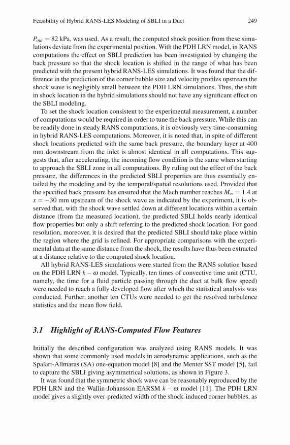
Pout = 82 kPa, was used. As a result, the computed shock position from these simu-lations deviate from the experimental position. With the PDH LRN model, in RANScomputations the effect on SBLI prediction has been investigated by changing theback pressure so that the shock location is shifted in the range of what has beenpredicted with the present hybrid RANS-LES simulations. It was found that the dif-ference in the prediction of the corner bubble size and velocity profiles upstream theshock wave is negligibly small between the PDH LRN simulations. Thus, the shiftin shock location in the hybrid simulations should not have any significant effect onthe SBLI modeling.
To set the shock location consistent to the experimental measurement, a numberof computations would be required in order to tune the back pressure. While this canbe readily done in steady RANS computations, it is obviously very time-consumingin hybrid RANS-LES computations. Moreover, it is noted that, in spite of differentshock locations predicted with the same back pressure, the boundary layer at 400mm downstream from the inlet is almost identical in all computations. This sug-gests that, after accelerating, the incoming flow condition is the same when startingto approach the SBLI zone in all computations. By ruling out the effect of the backpressure, the differences in the predicted SBLI properties are thus essentially en-tailed by the modeling and by the temporal/spatial resolutions used. Provided thatthe specified back pressure has ensured that the Mach number reaches M∞ = 1.4 atx = −30 mm upstream of the shock wave as indicated by the experiment, it is ob-served that, with the shock wave settled down at different locations within a certaindistance (from the measured location), the predicted SBLI holds nearly identicalflow properties but only a shift referring to the predicted shock location. For goodresolution, moreover, it is desired that the predicted SBLI should take place withinthe region where the grid is refined. For appropriate comparisons with the experi-mental data at the same distance from the shock, the results have thus been extractedat a distance relative to the computed shock location.
All hybrid RANS-LES simulations were started from the RANS solution basedon the PDH LRN k−ω model. Typically, ten times of convective time unit (CTU,namely, the time for a fluid particle passing through the duct at bulk flow speed)were needed to reach a fully developed flow after which the statistical analysis wasconducted. Further, another ten CTUs were needed to get the resolved turbulencestatistics and the mean flow field.
3.1 Highlight of RANS-Computed Flow Features
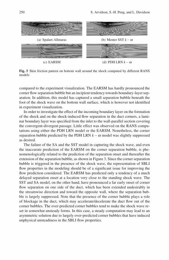
Initially the described configuration was analyzed using RANS models. It wasshown that some commonly used models in aerodynamic applications, such as theSpalart-Allmaras (SA) one-equation model [8] and the Menter SST model [5], failto capture the SBLI giving asymmetrical solutions, as shown in Figure 3.
It was found that the symmetric shock wave can be reasonably reproduced by thePDH LRN and the Wallin-Johansson EARSM k −ω model [11]. The PDH LRNmodel gives a slightly over-predicted width of the shock-induced corner bubbles, as
250 S. Arvidson, S.-H. Peng, and L. Davidson
(a) Spalart-Allmaras (b) Menter SST k−ω
(c) EARSM (d) PDH LRN k−ω
Fig. 3 Skin friction pattern on bottom wall around the shock computed by different RANSmodels
compared to the experiment visualization. The EARSM has hardly pronounced thecorner flow separation bubble but an incipient tendency towards boundary-layer sep-aration. In addition, this model has captured a small separation bubble beneath thefoot of the shock wave on the bottom wall surface, which is however not identifiedin experiment visualization.
In order to investigate the effect of the incoming boundary layer on the formationof the shock and on the shock-induced flow separation in the duct corners, a lami-nar boundary layer was specified from the inlet to the wall-parallel section coveringthe convergent-divergent passage. Little effect was observed on the RANS compu-tations using either the PDH LRN model or the EARSM. Nonetheless, the cornerseparation bubble predicted by the PDH LRN k−ω model was slightly suppressedas desired.
The failure of the SA and the SST model in capturing the shock wave, and eventhe inaccurate prediction of the EARSM on the corner separation bubble, is phe-nomenologically related to the prediction of the separation onset and thereafter theextension of the separation bubble, as shown in Figure 3. Since the corner separationbubble is triggered in the presence of the shock wave, the representation of SBLIflow properties in the modeling should be of a significant issue for improving theflow prediction considered. The EARSM has predicted only a tendency of a muchdelayed separation onset at a location very close to the standing shock wave. TheSST and SA model, on the other hand, have pronounced a far early onset of cornerflow separation on one side of the duct, which has been extended undesirably inthe streamwise direction and toward the opposite wall, where the separation bub-ble is largely suppressed. Note that the presence of the corner bubble plays a roleof blockage in the duct, which may accelerate/decelerate the duct flow out of thecorner bubbles. The over-predicted corner bubbles tend to make the shock wave re-set in somewhat unsteady forms. In this case, a steady computation may lead to anasymmetric solution due to largely over-predicted corner bubbles that have inducedunphysical unsteadiness in the SBLI flow properties.

Feasibility of Hybrid RANS-LES Modeling of SBLI in a Duct 251
4 Results and Discussion
All the hybrid RANS-LES computations are capable of resolving, to different ex-tents, turbulent structures on the two meshes used. Most of the resolved structuresare located in the shock-induced flow separation region in the duct corner, as il-lustrated by the resolved instantaneous flow pattern on the bottom wall surface inFigure 4. All simulations have captured the corner flow separation in the form of athree-dimensional recirculating bubble with its ”eye” shifting slightly from the wallsurface. For different models, grid resolutions and time steps (not shown), however,variations can be observed in the time-averaged flow fields, most sensibly on theshape and extension of the separation bubble. It is also observed that the size of thebubble is over-predicted in all simulations.
(a) Case 2: Instantaneous (b) Case 2: Time averaged
(c) Case 3: Instantaneous (d) Case 3: Time averaged
(e) Case 4: Instantaneous (f) Case 4: Time averaged
(g) Case 6: Instantaneous (h) Case 6: Time averaged
Fig. 4 Skin friction pattern on bottom wall around shock
The resulting time-averaged flow fields with SA-DES and HYB0 are symmetricabout the central section. The HYB0 (Case 2) and SA-DES (Case 3) computationshave produced rather similar flow scenarios on the coarse grid with the same timestep. For the SA-DES and HYB0 simulations, a major part of the corner bubbleis treated in LES mode. The shielding function used in DDES does not respondproperly to the separated flow in the corner bubble, where only very large tur-bulent structures are resolved, since a large part of the separation is modeled bythe RANS mode. For the SA-DES and HYB0 simulations, a separation bubble canclearly be identified in each corner with resolved turbulent structures enclosed. With
252 S. Arvidson, S.-H. Peng, and L. Davidson
SA-DDES, on the other hand, the instantaneous corner separation bubble movesfrom side to side, bursting and rebuilding with a low frequency. Due to this lowfrequency behaviour, the corner separation bubbles in the SA-DDES simulation re-quire a much longer simulation time for time-averaging analysis. Since ten CTUshave been used for time averaging in all simulations, this might explain why aslightly asymmetric time-averaged flow field is achieved with SA-DDES as seen inFigure 4 (f).
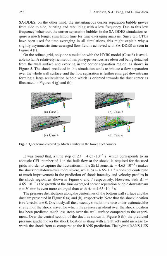
On the refined grid, only one simulation with the HYB0 model (Case 6) is avail-able so far. A relatively rich set of hairpin-type vortices are observed being detachedfrom the wall surface and evolving in the corner separation region, as shown inFigure 5. The shock predicted in this simulation tends to initiate a flow separationover the whole wall surface, and the flow separation is further enlarged downstreamforming a large recirculation bubble which is oriented towards the duct center asillustrated in Figures 4 (g) and (h).
(a) Case 2 (b) Case 3
(c) Case 4 (d) Case 6
Fig. 5 Q-criterion colored by Mach number in the lower duct corners
It was found that, a time step of Δ t = 4.65 · 10−6 s, which corresponds to anacoustic CFL number of 1 in the bulk flow at the shock, is required for the usedgrids in order to capture the fluctuations in the SBLI zone. Δ t = 4.65 ·10−5 s makesthe shock breakdown even more severe, while Δ t = 4.65 ·10−7 s does not contributeto much improvement in the prediction of shock intensity and velocity profiles inthe shock region, as shown in Figure 6 and 7 respectively. However, with Δ t =4.65 ·10−7 s the growth of the time-averaged corner separation bubble downstreamx = 30 mm is even more enlarged than with Δ t = 4.65 ·10−6 s.
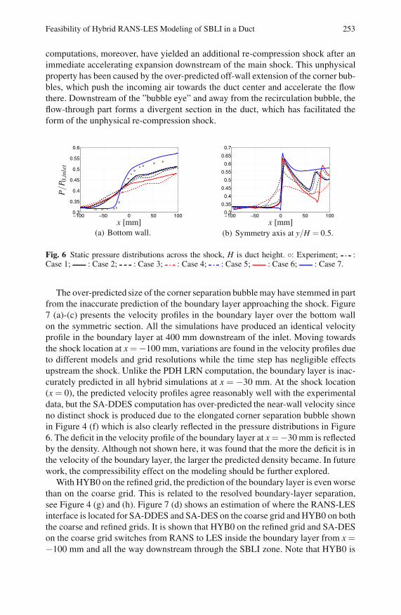
The pressure distributions along the centerlines of the bottom wall surface and theduct are presented in Figure 6 (a) and (b), respectively. Note that the shock locationis referred to x= 0. Obviously, all the unsteady simulations have under-estimated thestrength of the shock wave, for which the pressure gradient over the shock locationhas been predicted much less steep over the wall surface compared to the experi-ment. Over the central section of the duct, as shown in Figure 6 (b), the predictedpressure gradient over the shock location is sharp with a relatively mild increase to-wards the shock front as compared to the RANS prediction. The hybrid RANS-LES
Feasibility of Hybrid RANS-LES Modeling of SBLI in a Duct 253
computations, moreover, have yielded an additional re-compression shock after animmediate accelerating expansion downstream of the main shock. This unphysicalproperty has been caused by the over-predicted off-wall extension of the corner bub-bles, which push the incoming air towards the duct center and accelerate the flowthere. Downstream of the ”bubble eye” and away from the recirculation bubble, theflow-through part forms a divergent section in the duct, which has facilitated theform of the unphysical re-compression shock.
−100 −50 0 50 1000.3
0.35
0.4
0.45
0.5
0.55
0.6
x [mm]
P/P
0,in
let
(a) Bottom wall.
−100 −50 0 50 1000.3
0.35
0.4
0.45
0.5
0.55
0.6
0.65
0.7
x [mm](b) Symmetry axis at y/H = 0.5.
Fig. 6 Static pressure distributions across the shock, H is duct height. : Experiment; :Case 1; : Case 2; : Case 3; : Case 4; : Case 5; : Case 6; : Case 7.
The over-predicted size of the corner separation bubble may have stemmed in partfrom the inaccurate prediction of the boundary layer approaching the shock. Figure7 (a)-(c) presents the velocity profiles in the boundary layer over the bottom wallon the symmetric section. All the simulations have produced an identical velocityprofile in the boundary layer at 400 mm downstream of the inlet. Moving towardsthe shock location at x =−100 mm, variations are found in the velocity profiles dueto different models and grid resolutions while the time step has negligible effectsupstream the shock. Unlike the PDH LRN computation, the boundary layer is inac-curately predicted in all hybrid simulations at x = −30 mm. At the shock location(x = 0), the predicted velocity profiles agree reasonably well with the experimentaldata, but the SA-DDES computation has over-predicted the near-wall velocity sinceno distinct shock is produced due to the elongated corner separation bubble shownin Figure 4 (f) which is also clearly reflected in the pressure distributions in Figure6. The deficit in the velocity profile of the boundary layer at x=−30 mm is reflectedby the density. Although not shown here, it was found that the more the deficit is inthe velocity of the boundary layer, the larger the predicted density became. In futurework, the compressibility effect on the modeling should be further explored.
With HYB0 on the refined grid, the prediction of the boundary layer is even worsethan on the coarse grid. This is related to the resolved boundary-layer separation,see Figure 4 (g) and (h). Figure 7 (d) shows an estimation of where the RANS-LESinterface is located for SA-DDES and SA-DES on the coarse grid and HYB0 on boththe coarse and refined grids. It is shown that HYB0 on the refined grid and SA-DESon the coarse grid switches from RANS to LES inside the boundary layer from x =−100 mm and all the way downstream through the SBLI zone. Note that HYB0 is

254 S. Arvidson, S.-H. Peng, and L. Davidson
0 400 800 1200 1600 20000
0.05
0.1
0.15
0.2
U [m/s]
y/H
(a) Effect of model.
0 400 800 1200 1600 20000
0.05
0.1
0.15
0.2
U [m/s](b) Effect of mesh.
0 400 800 1200 1600 20000
0.05
0.1
0.15
0.2
U [m/s]
y/H
(c) Effect of time step.
0 1 0 1 0 1 0 1 0 1 0
0.05
0.1
0.15
0.2
RANS/LES(d) RANS-LES interface.
Fig. 7 Velocity profiles and RANS-LES switch location on the symmetric central section at400 mm downstream the inlet (the first profile on the left-hand side in each figure) and atx =-100, -30, 0, 30 mm from the shock, H is duct height. (a) Coarse grid, Δ t = 4.65 · 10−6
s. (b) HYB0 model, Δ t = 4.65 ·10−6 s. (c) HYB0 model, coarse grid. (d) RANS-LES switchlocation, RANS: 0 and LES: 1. : Experiment; : Case 1; : Case 2; : Case 3; :Case 4; : Case 5; : Case 6; : Case 7.
similar to a wall-modeled LES approach, which should be able to handle the switchfrom RANS to LES inside the boundary layer provided that the grid is sufficientlyfine. However, the grid upstream the SBLI zone where high velocities are presenthave shown to be too coarse even in the refined case for a model such as HYB0.This contributes to an inaccurate prediction of the boundary-layer flow due to anunder-resolved LES, which in turn contributes to the increased over-prediction ofthe corner bubble together with the stronger shock for this case. Downstream of theshock at x= 30 mm, the HYB0 simulation on the refined grid gives a different shapecompared to the measured profile in association to the over-predicted separationbubble.
5 Concluding Remarks
Testing of hybrid RANS-LES modeling has been conducted in comparison withavailable experimental data for the SBLI taking place in a rectangular duct flowat M∞ = 1.4. All the studied hybrid RANS-LES models have failed to capture theunderlying physics of the shock-induced corner flow separation. The standing shockwave is collapsed in association to the prediction of the corner flow separation.

Feasibility of Hybrid RANS-LES Modeling of SBLI in a Duct 255
Contrary to flows past a bluff-body with massive separation, the shock-inducedflow separation is of shallow type and is enclosed in the duct corner and partlyembedded in the boundary layer. This means that the separation bubble and theshock wave standing through the near-wall boundary layer have been dealt with byboth the LES and RANS modes. This is very challenging for hybrid RANS-LESmodeling, particularly for the RANS-LES interface.
The modeling demands special attention paid to the RANS-LES interface in rela-tion to the local grid resolution. Even for DDES-type models, the use of a shieldingfunction is not justified in the region of the separation zone. The shielding functionhas played a role as desired in the boundary layer upstream the SBLI zone but doesnot respond properly to the separated region which, as with the SST model, haspredicted a much earlier onset of the corner flow separation and has made the cor-ner separation bubble largely over-predicted. The poorly predicted shock wave andcorner separation bubble in the SA-DDES simulation is not only due to the DDESformulation but also to the underlying SA RANS model incorporated. The locationof the simulated bubble onset is thus very important and essential in the predictionof corner bubble size. A too early predicted onset and an exaggerated corner bubblewill breakdown the shock wave and form an unphysical re-compression shock.
To capture the flow physics and resolve the corner separation bubbles a wall-modeled LES approach, like the HYB0 model, might be an alternative providedthat the grid is sufficiently fine in the LES region. The grids used in this study haveshown to be too coarse, at least upstream the SBLI zone, and hence not fulfill therequirement for such a model. The use of a wall-modeled LES approach in the fulldomain for internal flows involving SBLI is computationally very costly and is todayimpossible to handle in industrial applications.
The study of the current SBLI flow has shown that a time step corresponding toan acoustic CFL number of 1 is required in the bulk flow at the shock for the gridsused in order to capture the fluctuations in the SBLI zone. Using the refined grid,large differences in the prediction of the corner separation and shock intensity werefound, as compared to the coarse grid.
In future work the modeling issues will be considered including the compress-ibility effect. Especially the work will focusing on further investigating the DDESapproach. To adapt it for shallow separations and incorporating a RANS base modelwhich has the capability to predict internal SBLI flows. A zonal formulation is in-teresting and will be studied. Such a formulation will treat the region upstream theSBLI zone with a RANS-like mesh and incorporate a URANS model which can pro-duce a boundary layer in good agreement with experimental data. The SBLI zonewill use a fine grid and a LES based approach to accurately resolve the turbulentstructures enclosed in the corner separation bubbles.
Acknowledgements. This work was primarily founded by the Swedish National FlightResearch Program (NFFP) and Saab Aeronautics, and was partially conducted within theEU project ATAAC, Contract No. 233710. Computational resources was supported by theSwedish National Infrastructure for Computing (SNIC).

256 S. Arvidson, S.-H. Peng, and L. Davidson
References
1. Bruce, P.J.K., Babinsky, H.: Unsteady shock wave dynamics. Journal of Fluid Mechan-ics 603, 463–473 (2008)
2. Bruce, P.J.K., Babinsky, H., Tartinville, B., Hirch, C.: An experimental and numericalstudy of an oscillating transonic shock wave in a duct. In: 48th AIAA Aerospace ScienceMeeting, Orlando, pp. 2010–2925 (2010)
3. Doerffer, P.: Description of Test Section and Measurements in a Nozzle for Shock Up-stream Mach Number M=1.45. In: Peng, S.-H., Doerffer, P., Haase, W. (eds.) Progress inHybrid RANS-LES Modelling, pp. 339–344. Springer, Heidelberg (2010)
4. Eliasson, P.: EDGE, a Navier-Stokes Solver for Unstructured Grids. Scientific report,FOI-R-0298-SE, Computational Aerodynamics Department, Aeronautics Division, FOI(2001)
5. Menter, F.R.: Two-Equation Eddy-Viscosity Turbulence Models for Engineering Appli-cations. AIAA Journal 32, 1598–1605 (1994)
6. Peng, S.-H.: Hybrid RANS-LES Modeling Based on Zero- and One-Equation ModelsFor Turbulent Flow Simulation. In: Proceedings of the 4th International Symposium onTurbulence and Shear Flow Phenomena, Williamsburg (2005)
7. Peng, S.-H., Davidson, L., Holmberg, S.: A Modified Low-Reynolds-Number k − ωModel for Recirculating Flows. Journal of Fluids Engineering 119, 867–875 (1997)
8. Spalart, P.R., Allmaras, S.R.: A One-Equation Turbulence Model for AerodynamicFlows. La Recherche Aerospatiale 1, 5–21 (1994)
9. Spalart, P.R., Deck, S., Shur, M.L., Squires, K.D.: A new version of detached-eddy sim-ulation, resistant to ambiguous grid densities. Theory of Computational Fluid Dynam-ics 20, 181–195 (2006)
10. Spalart, P.R., Jou, W.-H., Strelets, M., Allmaras, R.: Comments on the Feasability of LESfor Wings, and on a Hybrid RANS/LES Approach. In: Advances in DNS/LES, Ruston,Lousiana, pp. 137–147 (1997)
11. Wallin, S., Johansson, A.: An explicit algebraic Reynolds stress model for incompress-ible and compressible turbulent flows. Journal of Fluid Mechanics 403, 89–132 (2000)