nÖmayg . - r ø a. b ø te otoyol - yapim.otoyolas.com.tr · cilalanıp, yol dokusunun aşınması...
TRANSCRIPT

OTOYOL A.Ş
. - NÖMAYG
KALİTE BİRİMİ
AGREGA CİLALANMA DEĞERİ (PSV – POLISHED STONE VALUE) VE
ASFALT AŞINMA TABAKALARININ SÜRTÜNME DİRENCİ (ROUGHNESS /
YÜZEY PÜRÜZLÜLÜĞÜ) HAKKINDA LİTERATÜR ARAŞTIRMASI
NÖMAYG Kalite Bölümü
Tarih: 22.08.2017
Revizyon No: 0
[OTOYOL A.Ş. / NÖMAYG KALİTE BÖLÜMÜ]
Aggregate in Asphalt Course / Polished Stone Value (PSV) Research (Turkish)

OTOYOL A.Ş
. - NÖMAYG
KALİTE BİRİMİ
THE TITLE OF BOOK:
AGGREGATE IN ASPHALT COURSE / POLISHED STONE VALUE (PSV) RESEARCH
KİTABIN ADI:
ASFALT TABAKASI AGREGALARI /
AGREGA CİLALANMA DEĞERİ (PSV) ÇALIŞMASI
Abstract Özet
Aggregates of volcanic origin (such as Basalt) are frequently used in construction of Stone Mastic Asphalt
wearing courses.
↓ However, these aggregates
↓
Mostly have a glassy texture and doesn’t have mineralization.
↓
Regarding to Turkey’s “Polished Stone Value” less than the required Min % 50 by Turkey’s State Directorate of Motorways, Motorways Technical Specification 2006
Revision to be obtained . ↓
A literature research regarding the methods used in UK about how to use aggregates having low PSV results in
asphalt wearing course. ↓
Even if aggregate PSV value is low in SMA layer ↓
It could be used by having “a good roadway surface roughness”
↓ This study is aimed to show how these are conducted in
UK
Additionally, information and explanations regarding methods to evaluate motorway pavement surface
roughness such as:
Otoyol kaplamalarının Taş Mastik Asfalt aşınma
tabakası imalatında sıklıkla volkanik kökenli kayaçlar (örneğin Bazalt) kullanılmaktadır.
↓
Ancak, bu tip agregalarda ↓
Genellikle camsı bir yapı olduğu ve kristalizasyon mevcut olmadığı için
↓ Karayolları Teknik Şartnamesi 2006 Revizyonu’
nda yer alan “Agrega Cilalanma Değeri” şartname limiti olan Min. % 50 değerinden
düşük elde edilebilmektedir.
↓ Düşük PSV değerine sahip agregaların asfalt
aşınma tabakalarında kullanımı ile ilgili İngiliterede yapılan uygulamalara ile ilgili
literatür araştırması. ↓
PSV değeri TMA tabakasında kullanım için düşük ise.
↓ Bu agregalar “iyi bir yol yüzey pürüzlülüğü” elde
edilerek kullanılabilir. ↓
Bu inceleme, bahsi geçen çalışmaların İngiltere’de nasıl yapıldığını gösterme hedefini
gütmektedir. Bunlara ilaveten, otoyol yüzey pürüzlülüğünün
ölçümü için mevcut olan birbirinden farklı yöntemler ve bunlar hakkında bilgiler
mevcuttur.

OTOYOL A.Ş
. - NÖMAYG
KALİTE BİRİMİ
• Full Scale Tire – ASTM [USA], • Sideway Force Coefficient / SCRIM – BS [Great
Britain], • Pendulum Test – BS [Great Britain], • Grip Test – BS [Great Britain], • Sand Patch Test – ASTM [USA]
• Tam Ölçekli Tekerlek – ASTM [Amerika], • Yanal Kuvvet Katsayısı / SCRIM -
BS[İngiltere] • Sarkaç Testi – BS [İngiltere], • Yol Tutuş Testi – BS [İngiltere], • Kum Yama Testi – ASTM [Amerika])
.

OTOYOL A.Ş
. - NÖMAYG
KALİTE BİRİMİ
Sayfa 2 / 19
AGREGA CİLALANMA DEĞERİ (PSV – POLISHED STONE VALUE) VE ASFALT AŞINMA
TABAKALARININ SÜRTÜNME DİRENCİ (ROUGHNESS / YÜZEY PÜRÜZLÜLÜĞÜ) HAKKINDA
LİTERATÜR ARAŞTIRMASI
1) TS EN 1097‐8:2010‐01 “AGREGALARIN MEKANİK VE FİZİKSEL ÖZELLİKLERİ İÇİN DENEYLER ‐ BÖLÜM
8:TAŞ PARLATMA DEĞERİNİN TAYİNİ” standardı, madde 5, Numune Alma başlığı altında aşağıdaki ifade bulunmaktadır:
“Laboratuvar şartlarında yeni üretilmiş olan veya bitümlü karışımlardan geri kazanılan agregalar, yanıltıcı sonuçlar verebileceğinden uygunluk deneylerinde kullanılmamalıdır.”
2) Konkasörde kırılan malzemenin de Cilalanma Değeri’nin şartname limitlerinin altında olması
durumunda, yol yüzeyinde mikro tekstürü sağlayan agrega ve onun PSV (cilalanma) değeri dışında,
sürtünme mekanizması içerisinde önemli bir öğe olan asfalt yüzeyinin pürüzlülüğü yani makro tekstürü
hakkında literatür çalışması yapılmış ve aşağıdaki sayfalarda konu bu yönüyle de irdelenmiştir.
2A)
Bu araştırma “ASPHALT PROFESSİONAL, NO 30, OCAK 2008 TARİHLİ DERGİDE TECHNICAL PAPER –
HIGHER SKID RESISTANCE AND LOW PSV, YÜKSEK KAYMA DİRENCİ VE DÜŞÜK CİLALANMA DEĞERİ“,
ismini taşımaktadır.
İnşaat, asfalt, taş ocakları, beton ve bunun gibi tüm alanlarda faaliyet gösteren İskoçya Leiths Ltd.
Şirketinin Teknik Müdürü Neil Anderson tarafından yayımlanan bu 4 sayfalık bir teknik çalışmada yer alan
hususlar, bu yayından Türkçeye çevrilip aşağıya Madde 3, Madde 4 ve Madde 5 olarak alıntılanmıştır.
Madde 3’de ayrıca konu ile ilgili teknik bilgiler de verilmiştir. Madde 5’i takiben bu konu “Sonuç ve
Öneriler” olarak ayrıca yorumlanmıştır.
Madde 3 : Kayma direnci ve İnceleme Seviyeleri (Sayfa 12):
“DMRB (Design Manual for Roads and Bridges [Yollar ve Köprüler İçin Tasarım El Kitabı] – Highways
England Kurumu, İngiltere)” uyarıncak tekerlek ve yol yüzeyi arasındaki sürtünme iki ana maddeden
etkilenmektedir:
1‐) Tekerlek ve yol yüzeyi arasındaki direnç
2‐) Lastikteki deformasyondan kaynaklanan enerji kaybı.
Ve kayma direncine etki eden ana iki faktör de:
a‐) Agreganın küçük ölçekteki mikro yüzey dokusu
b‐) Yol yüzeyinin makro dokusu
[OTOYOL A.Ş. / NÖMAYG KALİTE BÖLÜMÜ]

OTOYOL A.Ş
. - NÖMAYG
KALİTE BİRİMİ
Sayfa 3 / 19
Madde 4: Yol Yüzey Dokusu (Sayfa 13) :
Yolun yüzey dokusu etki eden faktörler ise 4 ana başlık altında toplanmıştır:
1‐) Agreganın düşük kalitede olması,
2‐) Yetersiz karışım oranları ve kontrol eksikliğinden kaynaklanan yoğun ve yumuşak yüzeyli karışımlar yapılması,
3‐) Kaplama yüzeyinin trafik etkileri ile cilalanması,
4‐) Karışımın optimum performans özellikleri uyarınca hazırlanmaması.
Madde 5 – Kritik Karışım Dizayn Parametreleri (Sayfa 13):
Bilindiği gibi, asfalt yüzey tabakası tasarlanırken bazı “kritik agrega ve karışım özellikleri” dikkate alınmak zorundadır.
Bunlar:
‐Karışımın cilalanma ve daha sonra yüzey dokusu kaybıyla sonuçlanacak trafikten kaynaklanan sıkışmaya karşı “direnç kabiliyeti” ,
‐Yüksek PSV değeri ve yüksek Agrega Aşınma Kaybı değerine sahip olan karışımlar da, tüm karışımın cilalanıp, yol dokusunun aşınması ile sonuçlanacak bozulumuna karşı, PSV değerinin bu durumu engelleyebileceğinden emin olmamalıyız.
‐Yüksek PSV değeri sadece agrega tanesinin direncini temsil etmektedir,
‐Karışımı içeren her bir unsurun fiziksel özellikleri önemlidir,
‐Karışımın tamamı ele alındığında, bazı farklı gradasyonların çok daha iyi tekstür (doku) ve karışım özellikleri verdiği söylenebilir.
Yukarıdaki sebeplerle, cilalanma direncine ek olarak, karışım gradasyonunun ve yüzey dokusunun da kaplamanın sürtünme direncine katkısı ayrıca değerlendirilmelidir. Aşağıdaki Tablo 1’de, Kuzey İskoçyada aynı taş ocağından üretilen agreganın fiziksel özellikleri verilmiştir (Sayfa 14)
Daha sonra, bu agrega ile Kuzey İskoçya’da farklı yerlerde imal edilen kaplamaların da sürtünme direnci performansları ölçülmüş ve bu değerler Tablo 2’de gösterilmiştir.
a‐) Mikro doku
(Agreganın dokusu)
b‐) Makro doku (Yol
yüzeyinin dokusu)
[OTOYOL A.Ş. / NÖMAYG KALİTE BÖLÜMÜ]
OTOYOL A.Ş
. - NÖMAYG
KALİTE BİRİMİ
Sayfa 4 / 19
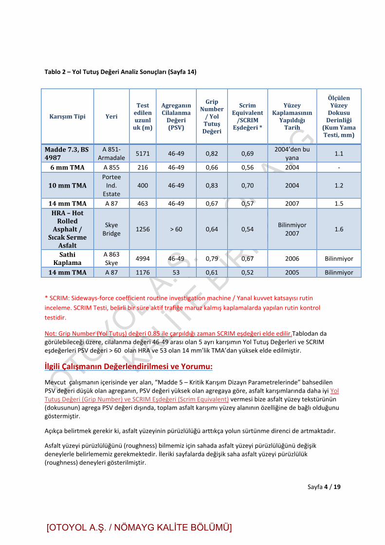
Tablo 2 – Yol Tutuş Değeri Analiz Sonuçları (Sayfa 14)
* SCRIM: Sideways‐force coefficient routine investigation machine / Yanal kuvvet katsayısı rutin
inceleme. SCRIM Testi, belirli bir süre aktif trafiğe maruz kalmış kaplamalarda yapılan rutin kontrol
testidir.
Not: Grip Number (Yol Tutuş) değeri 0.85 ile çarpıldığı zaman SCRIM eşdeğeri elde edilir.Tablodan da görülebileceği üzere, cilalanma değeri 46‐49 arası olan 5 ayrı karışımın Yol Tutuş Değerleri ve SCRIM eşdeğerleri PSV değeri > 60 olan HRA ve 53 olan 14 mm’lik TMA’dan yüksek elde edilmiştir.
İlgili Çalışmanın Değerlendirilmesi ve Yorumu:
Mevcut çalışmanın içerisinde yer alan, “Madde 5 – Kritik Karışım Dizayn Parametrelerinde” bahsedilen PSV değeri düşük olan agreganın, PSV değeri yüksek olan agregaya göre, asfalt karışımlarında daha iyi Yol Tutuş Değeri (Grip Number) ve SCRIM Eşdeğeri (Scrim Equivalent) vermesi bize asfalt yüzey tekstürünün (dokusunun) agrega PSV değeri dışında, toplam asfalt karışımı yüzey alanının özelliğine de bağlı olduğunu göstermiştir.
Açıkça belirtmek gerekir ki, asfalt yüzeyinin pürüzlülüğü arttıkça yolun sürtünme direnci de artmaktadır.
Asfalt yüzeyi pürüzlülüğünü (roughness) bilmemiz için sahada asfalt yüzeyi pürüzlülüğünü değişik deneylerle belirlememiz gerekmektedir. İleriki sayfalarda değişik saha asfalt yüzeyi pürüzlülük (roughness) deneyleri gösterilmiştir.
KarışımTipi Yeri
Testedilenuzunluk(m)
AgreganınCilalanmaDeğeri(PSV)
GripNumber/YolTutuşDeğeri
ScrimEquivalent/SCRIMEşdeğeri*
YüzeyKaplamasınınYapıldığıTarih
ÖlçülenYüzeyDokusuDerinliği(KumYamaTesti,mm)
Madde7.3,BS4987
A 851‐ Armadale
5171 46‐49 0,82 0,69 2004’den bu
yana 1.1
6mmTMA A 855 216 46‐49 0,66 0,56 2004 ‐
10mmTMAPortee Ind. Estate
400 46‐49 0,83 0,70 2004 1.2
14mmTMA A 87 463 46‐49 0,67 0,57 2007 1.5
HRA–HotRolledAsphalt/
SıcakSermeAsfalt
Skye Bridge
1256 > 60 0,64 0,54 Bilinmiyor
2007 1.6
SathiKaplama
A 863 Skye
4994 46‐49 0,79 0,67 2006 Bilinmiyor
14mmTMA A 87 1176 53 0,61 0,52 2005 Bilinmiyor
[OTOYOL A.Ş. / NÖMAYG KALİTE BÖLÜMÜ]

OTOYOL A.Ş
. - NÖMAYG
KALİTE BİRİMİ
Sayfa 5 / 19
2B) “TAKE THE HIGH ROAD (YOLUN KALİTESİNİ ARTTIRIN) – OCAK 2014 / NEIL ANDERSON (LEITH LTD. TEKNİK MD. İNGİLTERE)”
Yine aynı yazarın (Neil Anderson), “Asphalt Technology, Ocak 2014” sayısında yayınlanan “Take the High
Road – Yolun Kalitesini Arttırın” teknik araştırma yazısı, “İskoçyada ki yol yüzey tabakasının
dayanımlarını (durabilite/dayanıklılık) arttırmak için İngiltere şartnamesinin yetersiz olması nedeniyle,
İskoç şartnamesinin kullanılmasının zorunluluğunu” açıklamaktadır.
a) Neil Anderson’un buraya alıntıladığımız çalışmasının, raporumuzun 4A maddesinde, “PSV değeri düşük
olan agrega ile yapılan asfaltlarda yüksek sürtünme değerleri (GRIP Numarası ve SCRIM Eşdeğeri)
alınabileceğini” teknik veri ve referanslar ile göstermiştir.
b) Burada 4B maddesinde, aşağıda alıntılanan çalışmasında ise “Asfalt yüzey tabakasının maksimum
agrega ebadının düşürülerek ilgili yol tabakasının sürtünme değerlerinin yüksek süratlerde dahi
arttırılması” konusu yine teknik veri / referans örnekleri ile anlatılmaktadır.
Asfalt Teknolojisi dergisindeki ilgili teknik yazının tamamı Türkçeye çevrilerek alıntılanmıştır:
“Take the High Road (Yolun Kalitesini Arttırın) Ocak 2014 / Neil Anderson (Leith Ltd. Teknik Md. İngiltere)”
Taş mastik asfalt ince‐yüzeyli kaplama sistemlerinde (THCS) yakın zamanlarda meydana gelen yüzey
yenilmeleri / bozulmaları nedeniyle kötü bir imaj oluşmaktadır. Genellikle bu bozulmaların nedeni olarak
zayıf asfalt serim teknikleri ve/veya kötü hava şartları gösterilmektedir. Diğer faktörler ise asfalt
karışımındaki yüksek boşluk oranları ve düşük bağlayıcı miktarları olabileceğinden, İskoç TS 2010
şartnamesi bu konulardaki eksiklikleri kapatmıştır. Bu dökümanın, Birleşik Krallık Otoyol İşleri Şartnamesi,
Madde 942’ye göre üretilen malzemelerden daha dayanımlı bir malzeme üretimini temin ettiği
kullanıcıları tarafından söylenmektedir.
Aberdeen merkezli Leiths Grup teknik müdürü Neil Anderson bu konuyla ilgili şu görüşü bildirmişri:
“Bağlayıcı miktarının arttırılması ve boşlukların azaltılması kaçınılmaz olarak daha yüksek dayanımlı bir
malzemenin elde edilmesini sağlamaktadır”.
Neil Anderson, İskoçyadaki A90 yolunun yeniden yüzey kaplamasının yapılması sırasında gerçekleştirilen
testler sonucunda elde edilen sonuçlara ithafen de: “Bu sonuçlar göstermektedir ki İskoç şartnamesinde
bulunan yaklaşımların Birleşik Krallık’daki yol imalatlarında kullanılması önemli faydalar sağlayacaktır”
görüşünü belirtmiştir.
İki şartname arasındaki oldukça önemli farklılılar bulunmaktadır. Madde 942 uyarınca ince yüzeyli
kaplama sistemleri (TSCS), ilgili trafik yoğunlukları ve saha sınıflaması uyarınca gereken BBA HAPAS
sertifikalarına sahip olmalıdır. İskoç sistemi bu sertifikaları talep etmemektedir. Madde 942 belirli bir
[OTOYOL A.Ş. / NÖMAYG KALİTE BÖLÜMÜ]

OTOYOL A.Ş
. - NÖMAYG
KALİTE BİRİMİ
Sayfa 6 / 19
tekerlek çekişi ve yüzey dokusu seviyesi talep etmekte ve bazı agrega özelliklerini tanımlayarak diğer
özelliklerin kontrat spesifik eklerde tanımlanmasını istemektedir. Yine bu ekte, aksi belirtilmedikçe 5 yıllık
servis garantisi verilmesi de talep edilmektedir. Yukarıda bahsedilen BBA HAPAS gerekleri aynı kaplama
farklı taş ocaklarında alınan malzeme ile yapıldığında da geçerli olmaktadır.
TS 2010 (Yakın zamanda Madde 942TS olarak adı değişecektir), İngiliz sisteminden daha detaylı
tariflemelerde bulunmaktadır (örneğin: bir polimer modifiye bağlayıcı, gradasyon ve bağlayıcı zarfı ve
tamamlanmış imalatın sahip olması gereken hava boşluğu miktarı gibi). TS 201 aynı zamanda tabaka
kalınlığı gereklerini, karışımda elyaf kullanımını, deformasyon direncini ve GRIP Tester (Kayma cihazı) ile
ölçülecek kayma mukavemeti değerlerini de tanımlamaktadır. Bunlara ilaveten her taşocağının her bir
karışım tipi için ayrıca onaylanması gerekmektedir.
Yüksek kaliteli polimer modifiye bağlayıcı kullanımının tanımlanmasının nedeni, bu malzemeyi içeren
karışım ile yapılan kaplamanın farklı hava sıcaklıkları altında hizmet verebilirliğinin temin edilmesidir. Bu
tip bağlayıcılar kaplamaya deformasyon direnci sağlamaktayken ek olarak da soğuk iklim şartlarındaki
çatlak oluşumlarına karşı direnci de arttırmaktadır.
İskoç şartnamesi ayrıca kullanılacak her ürün için dört aşamalı bir Tip Onayı Kurulum Denemesi (Type
Approval Installation Trial – TAIT) gerekliliği getirmiştir. TS 2010’un parçası olarak verilen “Rehberlik
Notları” ise istenen geometrinin sağlanması için malzeme boyutlarının seilmesi ya da beklene gerilim
değerleri gibi konularda önemli yönlendirmeler içermektedir.
Erken dönem kayma direnci gerekleri, cilalanma değeri (PSV) kriterleri ile beraber TS 2010’a eklenmiş
olup kayma direnci gerekleri İngiliz Yol ve Köprüler için Tasarım El Kitabı Kısım HD 36/06’da belirtilen
değerlerden yüksek tutulmuştur.
Neil Anderson: “TS 2010’da, daha sürdürülebilir bir seçenek olan yerel agregaların kullanılması fırsatı
sunulmuştur ancak bu seçene İngiliz HD 36/06 Tablo 3.1’in dışında tutulmuştur” ifadesini kullanmıştır.
İskoç sisteminin ilginç bir kısmı da sürtünme direncinin ölçülmesi için kaplama yüzeyinin test edilmesidir.
Farklı yüzey kaplamalarından elde edilen sonuçların toplanarak değerlendirilmesi, proje şartnamelerini
yazacak kişilerin farklı malzeme tiplerini değerlendirmesine izin vermektedir.
Belirli agrega tipleri ve karışım dizaynları kullanılarak, İngiliterede sıklıkla kullanılan yüksek sürtünmeli
yüzeylerin (bu tür kaplamalar İngilterede yıllardan beri kullanılmakta olup genellikle 5 ila 10 yıl arası
ömürlüdür) sahip olduğu sürtünme direnci özellikleri ince kalınlığa sahip yüzey kaplamalarından elde
edilebilmektedir
[OTOYOL A.Ş. / NÖMAYG KALİTE BÖLÜMÜ]

OTOYOL A.Ş
. - NÖMAYG
KALİTE BİRİMİ
Sayfa 7 / 19
Neil Anderson “Yeni tamamlanmış olan A90 otoyolunun aşınma tabakasının yenilenmesi işine ait
kontratta Madde 942’ye uygun, polimer modifiye bağlayıcılı ve nominal maksimum agregaga boyu 10
mm olan ve nominal kalınlığı 30 mm olan 2.5 km uzunluğunda bir ince kaplama istenmekteydi” ifadesini
kullanmıştır.
Şartname gereğince, cilalanma değeri (PSV) min. 55, maksimum agrega aşınma değeri (AAD / AAV) 14 ve
yapraksallık indeksi değeri (FI) 20 olan bir agrega tanımlanmıştı. Tekerlek çekiş seviyesi 3 ve yol/lastik
gürültü seviyesi 1 ile beraber yüzey kaplaması için EME2 destek tabakası ve son olarak 5 yıllık bir
performans garantisi ile beraber tanımlanmıştır.
Yine Neil Anderson konu ile ilgili olarak: “Yeni inşaatın iki kısmı cilalanma değeri (PSV) 68’den yüksek olan
agrega gerektirmekteydi. Ancak, ince yüzey kaplamalarında yüksek cilalanma direnci agrega kullanılan
karışımlar, düşük cilalanma direnci olan agregalar kullanılan karışımlardan daha az duraylılığa sahip
olmaktadır” ifadesini kullanmıştır.
Müteahhit Leiths firması hem TS 2010 hem de proje sözleşmesinin gereklerini yerine getirebilecek yeni bir
malzeme önerisinde bulunmuştur. Neil Anderson konu ile ilgili olarak “ Yerel bir granit taş ocağından elde
edilen ve cilalanma değeri (PSV) 56 olan agregalar ile iki farklı TMA karışımı (10 mm ve 6 mm) ile hede
kalınlığı 35 mm olan iki kaplama yapılmasına karar verilmiştir” ifadesinde bulunmuştur.
Bağlayıcı olarak ise, Leiths firması Nynas Nypol 103 marka, önemli ölçüde deformasyon direnci ve
çatlama direnci gösteren, yüksek derecede modifiye edilmiş elastomeric bağlayıcı (modifiye bitüm)
kullanmıştır.
TS 2010 şartnamesine uyulabilmesi için, aşama 1 ve aşama 2 Tip Onay Kurulum Denemesi (TAIT)
tamamlanmıştır. Bu aşamalar laboratuvar karışım dizaynlarının yapılması, karışımın üretilmesi ve sahada
serilmesine yönelik deneme çalışmalarını içermektedir. Bu çalışmaların sonuçları tatmin edici bulununca
malzeme A 90 yolunun otoyol kısmında deneme serimine başlanmıştır. İskoçya Ulaşım departmanı
(Transport Scotland) malzemelerin kurulumunda, tüm operatörlerin eğitim kayıtlarının sunulması da dahil
en iyi koşul ve uygulamaların yapılmasında ısrar etmiştir.
Serimi yapılmış kaplamalarda, her 20 metrede alternatif tekerlek temas noktalarında nükleer yoğunluk
ölçer ile sıkışma tayinleri de dahil olmak üzere geniş kapsamlı testler yapılmıştır. Kaplamadaki boşlukların
şartname gereklerini sağladığı da teyit edilmiştir. Kontratta belirtilen iş tamamlandıktan hemen sonra
GRIP (Sabit kayma test cihazı) ile ölçümler yapılmış ve 0.7’den (SCRIM ‐ Yatay kuvvet katsayısı rutin
inceleme makinesi eşdeğeri ise 0.62) yüksek değerlere ulaşılmıştır. Bu değerler, şartnamede istenen
değerden yüksek olup Sınıf 3 bir kaplama için de istenen 0.55 SCRIM değerinden yüksektir.
[OTOYOL A.Ş. / NÖMAYG KALİTE BÖLÜMÜ]
OTOYOL A.Ş
. - NÖMAYG
KALİTE BİRİMİ
Sayfa 8 / 19
A 90 projesinde, ana eksenden daha fazla sürtünme direnci istenen kavşaklarda 6 mm nominal
maksimum agrega boyuna sahip TMA karışımı serilmiştir. Bu karışımın hazırlanmasında aynı taş
ocağından elde edilen ve 73 cilalanma (PSV) değerine sahip agrega fraksiyonu kullanılmıştır. 6 mm’lik
TMA karışımının erken dönem sürtünme direnci, 10 mm’lik aynı agrega ile yapılan kaplamanın sürtünme
direncinden çok az yüksek miktarda tespit edilmiştir.
Neil Anderson, konu ile ilgili olarak “Yakın zamanda yapılan çalışmalar göstermiştir ki 6 mm’lik karışımlar,
daha büyük agregalar ile yapılan karışımlar ile karşılaştırıldığında yüksek miktardaki sürtünme direnci
değerlerini korumuştur. İskoşyada yapılan araştırmalar göstermiştir ki, küçük agregalar cilalanma (PSV)
değerinden bağımsız olarak yüksek hızlarda yüksek kayma direnci sağlamış ayrıca da yüksek hızlarda da
daha iyi kayma direncine sahip olmuşlardır” ifadesinde bulunmuştur.
Kaplamada, altı ay ve iki yıl sonra yeniden GRIP testi gerçekleştirilecektir.
Neil Anderson sonuç olarak aşağıdaki ifadeleri kullanılmıştır: “Yüksek bağlayıcıya sahip ve istenen boşluk
oranında üretilen bu ürün, Madde 942’ye göre imal edilen standart bir üründen daha duraylı olmak
zorundadır. İnanıyorum ki ince kaplamalardaki bozulmalar yüksek boşuk ve düşük bağlayıcı içeriği ile
direkt olarak ilişkilendirilebilir”
“Aynı asfalt plenti ve iş gücü kaynakları TS 2010 ve Madde 942’ye göre üretilmiş iki malzeme söz konusu
olduğunda TS 2010 şartnamesi takip edilerek üretilen malzemenin daha dayanıklı olacağı söz konusu
olduğundan bu şartnamenin kullanılması daha mecburi olacaktır. GRIP test cihazının kullanılması da
performans testlerini yeni bir seviyeye taşıyacaktır.”
[OTOYOL A.Ş. / NÖMAYG KALİTE BÖLÜMÜ]

OTOYOL A.Ş
. - NÖMAYG
KALİTE BİRİMİ
Sayfa 9 / 19
3) YOL AŞINMA YÜZEY TABAKASINDA SÜRTÜNME DİNAMİĞİ VE
ASFALT DOKUSU (TEKSTÜRÜ) – ARAÇ LASTİĞİ İLİŞKİLERİ TEKNİK
PRENSİPLERİ
Yol kaplamalarında tekerleğin asfalt ile sürtünme mekanizmaları konusunda, “Pavement Maintenance
and Advanced Materials (Yol kaplama bakımları ve gelişmiş malzemeler)” / Utah Üniversitesi İnşaat
Mühendisliği / ABD – 2011 yılı yayınında, sürtünme mekanizmasını oluşturan araç lastiği ile yolun mikro
ve makro tekstürü arasındaki ilişki bu yayında açıklanmaktadır.
Bahse geçen konu, kitaptan aşağıya alıntılanmıştır
(https://pavemaintenance.wikispaces.com/CVEEN+7570‐+Spring+2011 )
Sürtünme Mekanizmaları
Kaplama sürtünmesi adezyon ve histerisis kuvvetlerinin kombinasyonu ile oluşmaktadır. Adezyon, araç
tekerleği ile kaplama yüzeyinin küçük ölçüde bağlanmasından kaynaklanır ve temas sırasındaki kesme
dayanımı ve temas alanının bir fonksiyonudur.
Histerisis ise, tekerleğin deformasyonundan dolayı kaybolan enerjiyi ifade eder ve tekerleğin kaplama
dokusunu sarma biçimi olarak ifade edilebilir.
Lastik Elementi
Adezyon
Ağırlıklı olarak yüzeyin mikro
seviyedeki pürüzlülüğüne bağlıdır.
Histerisis
Ağırlıklı olarak yüzeyin makro
seviyedeki pürüzlülüğüne bağlıdır.
Sürtünme Kuvvetini Oluşturan Adezyon ve Histerisis Bileşenlerinin Gösterimi (NCHRP, 2009)
[OTOYOL A.Ş. / NÖMAYG KALİTE BÖLÜMÜ]

OTOYOL A.Ş
. - NÖMAYG
KALİTE BİRİMİ
Sayfa 10 / 19
Sürtünme kuvvetinin her iki bileşeni de ağırlıklı olarak yol kaplamasının yüzey karakteristiklerine bağlıdır.
Buna ilaveten ortam sıcaklığı, araç hızı ve çevre faktörleri de sürtünme kuvvetine etki eden faktörlerdir.
Adezyon kuvveti kaplama – lastik teması sırasında oluşmakta olup agregaların mikro dokusuna en hassas
olan kuvvettir. Adezyon kuvveti genel olarak yumuşak ve kuru kaplamalardaki toplam sürtünmeyi kontrol
eden bir faktördür. Histerisis kuvveti ise daha çok makro dokuya tepki verir ve ıslak ve pürüzlü
kaplamalardaki sürtünme kuvvetine baskın olarak etki eder (NCHRP 2009)
Kaplama Yüzeyi Dokusu
Yüzey Dokusu, kaplamanın yüzeyinin gerçek düz bir yüzeyden sapması olarak tanımlanmaktadır.
Sınıflandırması ise dalgaboyu (I) ve tepeden tepeye dalga genişliği / amplitüd (A) üzerinden
yapılmaktadır. Üç çeşit yüzey dokusu bulunmakta olup bunlar:
1‐) Mikro doku (l< .02 in [.5 mm], A = .04 ‐ 20 mils [1 ‐ 500 mm]); Yüzey pürüzlülüğü kalitesi gözle çok zor
gözlenebilir ya da mikroskobik seviyededir.
2‐) Makro doku (l= .02 ‐ 2 in [.5 ‐ 50 mm], A = .005 ‐ .8 in [.1 ‐ 20 mm]); Yüzey pürüzlülüğü kalitesi karışım
özellikleri ve yüzey bitirme işleri metodları ile tanımlanır.
3‐) Mega doku (l= 2 ‐20 in [50 ‐ 500 mm], A = .005 ‐ 2 in [.1 ‐ 50 mm]); Kaplama yüzeyindeki bozukluklar
ya da dalgalı yapılanmalar ile tanımlanır.
Bu yüzey dokusu seviyeleri aşağıda gösterilmiş olup her bir seviyenin etkileri de bir sonraki tabloda
gösterilmektedir:
[OTOYOL A.Ş. / NÖMAYG KALİTE BÖLÜMÜ]

OTOYOL A.Ş
. - NÖMAYG
KALİTE BİRİMİ
Sayfa 11 / 19
Tek bir
agrega
Referans uzunluk
Kısa bir yol
mesafesi
Tekerlek
Tekerlek – kaplama
temas alanı
Pürüzlülük / Uyumsuzluk
Mega doku
Makro doku
Mikro doku
50 defa büyütme
5 defa büyütme
5 defa büyütme
Basitleştirilmiş Yüzey Dokusu Aralıkları (NCHRP 2009)
Doku Dalgaboyu
Mikro doku Makro doku Mega doku Pürüzlülük / Uyumsuzluk
Sürtünme
Harici Ses
İç Ses
Su sıçratma
Yuvarlanma direnci
Lastik Aşınması Lastik / Araç Hasarı
Not: Daha koyu gölgelendirme, belirtilen aralıkta doku için daha olumlu etkilere işaret etmektedir.
Doku dalgaboyu kaplama üzerindeki etkileri (NCHRP 2009)
[OTOYOL A.Ş. / NÖMAYG KALİTE BÖLÜMÜ]

OTOYOL A.Ş
. - NÖMAYG
KALİTE BİRİMİ
Sayfa 12 / 19
Herhangi bir kaplamanın sürtünme direncine etki eden bir çok ilave faktör olabilir. Bunlardan bazıları
aşağıdaki tabloda verilmiştir:
Kaplama Yüzey Karakteristikleri
Araç İşletme Parametreleri
Tekerlek Özellikleri Çevre Şartları
Mikro doku
Makro dolu
Mega doku, yüzey uyumsuzlukları
Malzeme özellikleri
Sıcaklık
Kayma hızı ‐Araç hızı ‐Fren hareketi
Sürüş manevrası ‐Dönüş ‐Sollama
Tekerlek
Lastik kanal tasarımı ve durumu
Lastiğin kauçuk içeriği ve sertliği
Lastik şişirme basıncı
Araç yükü
Sıcaklık
İklim ‐Rüzgar ‐Sıcaklık ‐Su (yağmur, yoğuşma) ‐Buz ve kar
Kirleticiler ‐Kayma önleyici malzemeler (tuz, kum) ‐Toz, çamur, moloz.
Sürücü ve araç harici faktörler içerisinde dikkate alınması gereken kombinasyon, düşük sürtünme
katsayısı / kayma numarası’na sahip olan kaplamalardaki ıslak yüzeylerine etkisidir. Genel olarak, çoğu
kuru kaplamanın sürtünme direnci yüksektir. Islak kaplamalardaki kazaların sayısı ise kuru kaplamalarda
meydana gelen kazaların neredeyse iki katı kadar fazladır (Romero n.d.).
Kaplama Sürtünmesine Etki Eden Çeşitli Faktörler
[OTOYOL A.Ş. / NÖMAYG KALİTE BÖLÜMÜ]

OTOYOL A.Ş
. - NÖMAYG
KALİTE BİRİMİ
Sayfa 13 / 19
4) PRATİKTE YER ALAN FARKLI ASFALT YÜZEYİ PÜRÜZLÜLÜK
(ROUGHNESS) DENEYLERİ VE PROJEDE YER ALAN KRİTERLERİ
1‐) ASTM E 274 – Standard Test Method for Skid Resistance of Paved Surfaces Using Full‐Scale Tire /
Kaplama Yüzeylerinin Sürtünme Direncinin tam Ölçekli Tekerlek ile Ölçülmesi için Standart Test Metodu
Belirli bir hızda çekilen römorkun tekerlerine önce su püskürtülüp hemen arkasından kilitlenerek asfalt
yüzeyi ile lastik arasında oluşan sürtünme direncinin ölçülmesi esasına dayanır. (Türkiyede ve Amerikada
yapılmaktadır / Tekerlek Blokesi ile Kayma Direnci Ölçümü Özel belli bir açı ile dizayn edilmiş tekerlek, önüne su püskürtülerek, tekerleğin
bloke edilmesi ile kayma direnci ölçümü gerçekleştirilir.)
Gebze‐Orhangazi‐İzmir Otoyolunun YİD Modeli ile Yapılması, İşletilmesi ve Devri İşine ait Teknik Gerekler,
Sayfa 80’de, bulunan tabloda Sürtünme Direnci maddesinde belirtilmektedir.:
IRI Uluslararası Düzgünsüzlük İndeksi (The international roughness
index IRI ) Standart bir pürüzlülük ölçümü oluşturmak ve boyuna profilde tekerlek izi seyahatinin karakteristiğini belirlemek için
kullanılır.
Genellikle tavsiye edilen birimler m/km ya da mm/m dir. Ancak m/km
de kulanılır. IRI, profil ölçümüne uygulanan matematiksel bir modeldir
ve çeyrek taşıt sistemini (QCS) kullanır. IRI, QCS deki
süspansiyonun kümülatif hareketinin sürüş uzunluğuna bölünmesiyle elde
edilir.
[OTOYOL A.Ş. / NÖMAYG KALİTE BÖLÜMÜ]

OTOYOL A.Ş
. - NÖMAYG
KALİTE BİRİMİ
Sayfa 14 / 19
IRI Değerinin Ölçülmesi:
Günümüzde yüzey pürüzlülüğü tipik olarak iki yöntemle sayısal olarak ifade edilmektedir. Bunlardan birincisi IRI (International Roughness Index – Uluslararası Yüzey Pürüzlülüğü İndeksi) diğeri de PSR (Present Serviceability Rating - Güncel Hizmet Verebilirlik Değeri) değerleridir. Bunların içinden IRI en yaygın olarak kullanılanıdır.
Sürtünme direnci, bir tekerleğin kaplama yüzeyi boyunca kayarak hareket etmesi önlendiğinde oluşan kuvvettir. Bu kuvvet önemli bir kaplama değerlendirme parametresidir çünkü sürtünme direncinin yetersiz ya da mevcut olmaması kazalarda artışa yol açabilir.
Agrega
Taneleri
Kuru durumda tekerlek
ile kaplama ilişkisi
Lastik
Islak durumda tekerlek
ile kaplama ilişkisi
[OTOYOL A.Ş. / NÖMAYG KALİTE BÖLÜMÜ]

OTOYOL A.Ş
. - NÖMAYG
KALİTE BİRİMİ
Sayfa 15 / 19
2‐) BS 7941‐1:2006 – Methods for measuring the skid resistance of pavement surfaces. Part 1:
Sideway‐force coefficient routine investigation machine / Kaplama yüzeylerinin sürtünme dirençlerinin
ölçülmesi için metodlar: Kısım 1 : Yatay kuvvet katsayısı rutin inceleme makinesi (20 derece açılı tekerlek frenlenir. Tekerlekte oluşan kuvvet okunarak, kayma sürtünme katsayısı elde edilir. 50 km/st hızla giderken ölçüm yapabilir).
[OTOYOL A.Ş. / NÖMAYG KALİTE BÖLÜMÜ]

OTOYOL A.Ş
. - NÖMAYG
KALİTE BİRİMİ
Sayfa 16 / 19
3‐) BS EN 13036‐4:2011 ‐ Road and airfield surface characteristics. Test methods . Method for
measurement of slip/skid resistance of a surface: The pendulum test / Yol ve hava alanı yüzey
karakteristikleri ‐ Deney yöntemleri ‐ Bölüm 4: Yüzeyin kayma/kızaklama direncinin ölçülmesi yöntemi:
Pandül deneyi. (British pandül testi ile doğrudan ölçülebilir. Pandül, yol yüzeyine düşürülür ve kadrandan kayma direnci katsayısı okunur)
4‐) BS 7941‐2:2000: Methods for measuring the skid resistance of pavement surfaces. Test method for
measurement of surface skid resistance using the GripTester braked wheel fixed slip device / Kaplama
yüzeylerinin sürtünme dirençlerinin ölçülmesi için metodlar: Kısım 2: Frenli tekerli sabit kayma cihazı
(GripTester) ile yüzey kayma direncinin ölçülmesi için test metodu.
Grip Tester cihazı, bir aksın içine yerleştirilmiş özel bir yumuşak kanallı tekerlek ile (ASTM tarafından
tanımlanmış ve tekil bir seri numarası olan) yatay çekme kuvveti ile tekerlekteki dikey yükü ölçecek
cihazlardan oluşmaktadır. Dinamik Sürtünme aşağıdaki resimde gösterilen formül ile hesaplanarak
bulunur:
[OTOYOL A.Ş. / NÖMAYG KALİTE BÖLÜMÜ]

OTOYOL A.Ş
. - NÖMAYG
KALİTE BİRİMİ
Sayfa 17 / 19
Hesaplanmış “Sürtünme Katsayısı” Tutunma Numarası (Grip Number ‐ GN) olarak isimlendirilmiştir.
Tutunma Numarasının (GN), Yatay kuvvet katsayısı rutin inceleme makinesi (SCRIM) cihazından elde
edilen Yan Kuvvet Katsayısı (Side Force Coefficient – SFC) ile aşağıdaki şekilde bir ilişkisi mevcuttur.
GN = SFC50 / 0.85 (Findlay Irvine)
GripTester cihazının ağırlığının büyük bir kısmı biçimli kanalları olan lastiklerle donatılmış iki teker
tarafından taşınmaktadır ve bu tekerler paslanmaz çelikten katı bir aks ile birbirine bağlanmıştır.
Bu aks, ölçüm tekerleğini zincir transmisyon sistemi kullanarak çekmektedir (bu transmisyon sistemi
32:27 azaltma oranına sahiptir)
Bilgisayar kontrollü bir su sistemi, ölçüm tekerleğinin altında önceden belirlenmiş kalınlıkta bir su filmi
oluşturacak şekilde su püskürtür. Deneyde kullanılan su miktarı, doğru miktarda su filmi kalınlığının
sağlaması için hız oranınca değişiklik göstermektedir.
Dikey Kuvvet (Tekerlekteki
Yük Fv)
Hareket
Yönü
Rotasyon
Sürtünme Kuvveti (Fh)
Sürtünme Katsayısı = ü ü
ğ ğ =
[OTOYOL A.Ş. / NÖMAYG KALİTE BÖLÜMÜ]

OTOYOL A.Ş
. - NÖMAYG
KALİTE BİRİMİ
Sayfa 18 / 19
Paslanmaz çelik aksa aynı zamanda bir mesafe kaydedici monte edilmiştir. Bu kaydedici mesafe ve hız
ölçümleri ile su akışının kontrolü için kullanılmaktadır. GPS cihazı ise referans olacak koordinatların
kaydetmektedir.
5‐) ASTM E965 – 15: Standard Test Method for Measuring Pavement Macrotexture Depth Using a
Volumetric Technique / Kaplama makro doku/tekstür derinliğinin volümetrik teknik ile ölçülmesi için
standart test metodu. ( Kum Yama Testi / Sand Patch Test )
Kum Yama testinde, belli miktardaki kum, yüzeye yayılır ve oluşan dairenin çapına göre, yüzeyin pürüzlü,
az pürüzlü veya pürüzsüz olduğuna karar verilir. Yüzey dokusu gözenekli ise, daha küçük yarıçaplı, daha
gözeneksiz ise daha büyük yarıçaplı daireler elde edilir.
Karayolları Teknik Şartnamesi 2006, Kısım 408 Taş Mastik Asfalt (TMA)’nın içinde 408.08 Sayfa 536’da,
“Yüzey Dokusu” bölümünde yer alan Kum Yama Testi ile ilgili kısımda şunlar söylenmektedir:
“Sıkıştırmadan sonra, Kum Yama Yöntemi (Sand Patch Method, ASTM E 965) ile ölçülen doku derinliği,
TMA Tip‐1 için 1.0 mm’den fazla ve TMA Tip – 2 için 0.80 mm’den fazla olacaktır.”
[OTOYOL A.Ş. / NÖMAYG KALİTE BÖLÜMÜ]

OTOYOL A.Ş
. - NÖMAYG
KALİTE BİRİMİ
Sayfa 19 / 19
Referanslar:
1‐) Design Manual for Roads and Bridges , Volume 7, Section 3, Part 1: Skidding Resistance – Highways
England, 2015. / Sayfa sayısının fazla olması nedeniyle ekte yer almamaktadır.
2‐) TS EN 1097‐8:2010 ‐ Agregaların mekanik ve fiziksel özellikleri için deneyler ‐ Bölüm 8: Taş parlatma
değerinin tayini / Ekte mevcuttur.
3‐) Karayolları Teknik Şartnamesi 2006 Kısım 408 Taş Mastik Asfalt / Ekte mevcut değildir.
4‐) “Asphalt Professional, No 30, January 2008 Technical Paper – Higher Skid Resistance and low PSV”,
Neil Anderson, Bsc MIAT, Technical Director Leiths (Scotland) Ltd. / Ekte mevcuttur.
5‐) “Take the High Road”, www.agg‐net.com, January 2014, Neil Anderson, Bsc MIAT, Technical Director
Leiths (Scotland) Ltd. / Ekte mevcuttur.
6‐) ASTM E274 – “Standard Test Method for Skid Resistance of Paved Surfaces Using a Full‐Scale Tire.” /
Ekte mevcuttur.
7‐) BS 7941‐1:2006 “Methods for measuring the skid resistance of pavement surfaces. Sideway‐force
coefficient routine investigation machine” / Ekte mevcuttur.
8‐) BS EN 13036‐4:2011 “Road and airfield surface characteristics. Test methods . Method for
measurement of slip/skid resistance of a surface: The pendulum test” / Ekte mevcut değildir.
9‐) BS 7941‐2:2000 “Methods for measuring the skid resistance of pavement surfaces. Test method for
measurement of surface skid resistance using the GripTester braked wheel fixed slip device” / Bu
standart, dökümanın yazım tarihinde elimizde mevcut olmayıp temin edildiğinde yeni revizyonda
eklenecektir
10‐) ASTM E 965 – “Standard Test Method for Measuring Pavement Macrotexture Depth Using a
Volumetric Technique” / Ekte mevcuttur.
11‐) “Pavement Maintenance and Advanced Materials” / Utah University Civil Engineering ‐ CVEEN
7570‐ Spring 2011 ( https://pavemaintenance.wikispaces.com/CVEEN+7570‐+Spring+2011 ) / Sayfa
sayısının fazla olması nedeniyle ekte yer almamaktadır. Verilen linkten bakılabilir.
[OTOYOL A.Ş. / NÖMAYG KALİTE BÖLÜMÜ]
OTOYOL A.Ş
. - NÖMAYG
KALİTE BİRİMİ
REFERANS 4 - “Asphalt Professional, No 30, January 2008 Technical
Paper – Higher Skid Resistance and low PSV”, Neil Anderson, Bsc MIAT,
Technical Director Leiths (Scotland) Ltd.
[OTOYOL A.Ş. / NÖMAYG KALİTE BÖLÜMÜ]

OTOYOL A.Ş
. - NÖMAYG
KALİTE BİRİMİ
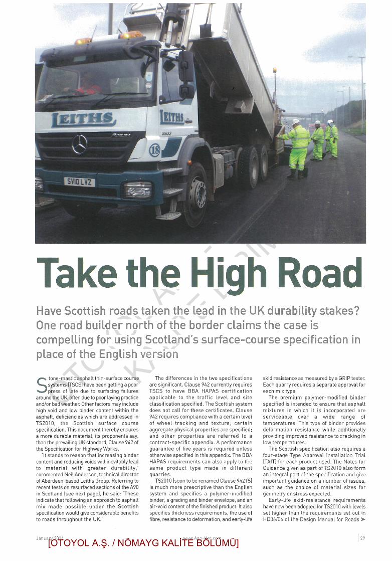
No 30 • January 2008
Asphalt Professional
Also in this issue:Investigation of skid resistance for a thin surfacing system2008 – a new dawnPlus all your regular features
LOW PSV CANNOT GIVE HIGH SKIDDING RESISTANCE
OR SO YOU THOUGHT...
Pict
ure
cour
tesy
ofCo
lasU
K
[OTOYOL A.Ş. / NÖMAYG KALİTE BÖLÜMÜ]

OTOYOL A.Ş
. - NÖMAYG
KALİTE BİRİMİ
January 2008 • asphalt professional 13
technical paper
Higher skid resistanceand lower PSV
ABSTRACT: The standards applied to the selection of aggregates for surfacing worksrequire that compliance with minimum polished stone values (PSV) is a primaryrequirement. The source of high PSV stone is often far removed from the surfacing site.Inevitably this means that stone has to be transported many miles at considerable costin order to meet PSV specification requirements.Thin surfacings have been introduced in recent times and PSV requirements have notbeen changed or modified to take account of the physical properties of these relativelynew materials. Many high PSV aggregates possess physical properties that are notsuitable for surface dressing or thin surfacing.In the North of Scotland the PSV of most aggregates falls within the range of 50-55. Thispaper was prompted by the results of a study carried out by Leith’s (Scotland) Ltd usingaggregates of a lower PSV to meet design requirements of skid resistance. When there isa device available such as the GripTester it is difficult to understand why the results arenot accepted as evidence of skid resistance.
N Anderson1
1 IntroductionThe Polished Stone Value (PSV) of an aggregate isconsidered to be a fundamental property of anyaggregate used in bituminous surface courses. Theconsideration of this physical property is unique tothe UK and is a significant driver to the selection ofaggregates for surfacing works.Hot Rolled Asphalt (HRA) is a traditional road
surfacing material in the UK and is principally asand carpet with pre-coated chips rolled into thesurface. A bitumen rich sand carpet by itself makesa slippery surface. The use of pre-coated chipsproduces a macro texture and the use of high PSVchips produces a good micro texture both of theseare important components of skid resistant HRAsurfacing. This paper demonstrates that thiswisdom does not apply to other types of surfacing.
2 PSVPSV is a standard laboratory measurement of skidresistance of a number of aggregate particles. Theminimum PSV’s to be applied to differentcategories of site and related to traffic flow aregiven in Table 3.1, Volume 7, Section 5 of theDesign Manual for Roads & Bridges (DMRB).Table 3.2 in the same section of the manual refersto the aggregate abrasion value which is a measureof the durability of the aggregate.Inspection of the former table shows that the
minimum PSV specified for most sites would be55. Traffic flows on most sites now are such that a50 PSV is rarely specified.
3 Skid resistance and investigatory levelsAccording to the DMRB friction between the tyreand road surface consists of two main components.1 Sliding resistance between tyre and roadsurface.
2 Loss of energy caused by deformation of thetyre.
And there are two main contributors to slidingresistance.a) The fine scale micro texture of the surfaceaggregate.
b) The macro texture of the road surface.Skidding Resistance Levels are
checked regularly on majorroads by the Sideways-force
1. Neil Anderson BSc MIATTechnical Director Leiths (Scotland) Ltd
1
Figure 1 —
Aggregate
sample:
Highland
Aggregates
[OTOYOL A.Ş. / NÖMAYG KALİTE BÖLÜMÜ]

OTOYOL A.Ş
. - NÖMAYG
KALİTE BİRİMİ
14 asphalt professional • January 2008
technical paper
Coefficient Routine Investigation Machine(Scrim). A full description of the equipment used isgiven in the DMRB, the test produces Scrim values.A table in Volume 7 Section 3 of the DMRB showsinvestigatory skidding resistance levels for differentsite categories. The tables referred to above containa column for the site category, and the defaultinvestigatory level is also shown in both tables. Theinvestigatory level is defined as the level of skidresistance at or below at which site investigation isto be undertaken.These documents and tables are quite clear; the
PSV and durability of the stone is specified and theperformance standard which the surfacing isrequired to meet is defined by the investigatorylevel specified. The only other requirementspecified is a sand patch test which measuressurface texture.
4 Surface textureThe stone type and source will determine PSV andAAV; the surface texture will be influenced by thephysical properties of the aggregate and the mixproperties. A combination of these factors willinfluence the level of skid resistance that can beachieved.Surface texture can be influenced by a number
of factors, some of the primary ones are:1) Poor quality aggregate.
The qualities of aggregate acceptable in abituminous mix in the UK permits a widerange of aggregates to be used. This increasesthe risk of using an unsuitable aggregate inheavily trafficked surface courses.
2) Poor mix proportioning or control leading toa dense smooth surfaced mix.There is no fundamental requirement in theUK to design any bitumen macadam or HRA
recipe mix. There are design requirements forHRA and some thin surfacing mixes used inheavily trafficked areas.
3) Polishing of the surface by traffic.Any mix which has not been designed orcontrolled to produce optimum properties willbe more or less susceptible to polishing bytraffic.
4). Not designing the mix to obtain optimumperformance properties.
5 Critical mix design parametersIt is apparent therefore that there are a number ofcritical aggregate and mix properties which shouldbe considered when designing a surface coursemix.• The ability of a mix to withstand polishingand further compaction which will result in aloss of surface texture. PSV does notnecessarily assist in any resistance topolishing of the overall mix and with someaggregates high PSV and high AAV canaccelerate the deterioration or loss of surfacetexture through wear. A high PSV doesindicate resistance to polishing of thataggregate particle.
• The physical properties of the ingredients.• The overall composition of the mix, certaingradings will produce better textures andvolumetric properties.
6 QuestionsThe foregoing begs a number of questions withregard to the interrelation of the various importantphysical properties. Four of the most importantquestions are:• What is the effect of PSV on skid resistance?• How important is the maintenance oftexture?
TEST Method Result
Polished Stone Value BS EN 1097-8:2000 46
Aggregate Abrasion Value BS EN 1097-8:2000 1.5%
Ten Per Cent Fines Value BS812: Part 111:1990 350Kn Dry
Particle Density Apparent BS EN 1097-6:2000 2.675Mg/m2
Water Absorption BS EN 1097-6:2000 0.9%
Soundness BS EN 1367-2 98%
Los Angeles Abrasion BS EN 1097-2:1998 16
Micro Deval Co-efficient BS EN 1097-2:1998 3
Table 1 — Aggregate Physical Properties
Figure 2 – 6mm Cariphalte TS Texture
[OTOYOL A.Ş. / NÖMAYG KALİTE BÖLÜMÜ]

OTOYOL A.Ş
. - NÖMAYG
KALİTE BİRİMİ
January 2008 • asphalt professional 15
technical paper
• How important is the mix composition?• Other than PSV which aggregate physicalproperties are critical?
The question is further complicated by the typesof surfacing available which can produce eithernegative or positive surface texture. Therequirements in the DMRB cover all types ofsurfaces from surface dressing and hot rolledasphalt (positive texture) to macadams and thinsurfacing (negative texture). A thin surfacingmaterial manufactured with a 65 PSV stone isdeemed to have the same skidding resistance as anasphalt with pre-coated chips of the same PSV.
7 Selection of aggregatesThese requirements ultimately drive the selectionof aggregates for all contracts. There is a conflictbecause high PSV aggregates are generally not the
most durable. Aggregates used in different types ofsurfacing rely on different properties to produceoptimum performance.8 Site experienceThe author has been involved in manufacturingbituminous mixes in the North of Scotland. Aprincipal quarry in this area was reputed toproduce aggregate with a PSV in the mid to low50’s. Recent tests have shown this assumption to beincorrect and that the PSV value is less than 50. Theaggregate in question although low PSV hasexceptional physical properties, see table 1.Various bituminous mixes have been produced
from aggregate from this quarry. The volumetricproperties of a BS 4987 clause 7.3 material wereverified using the Marshall mix design apparatus.The mix was proportioned within the limits of theBS 4987 envelope to produce the best texture. The
Materialtype Location
Lengthtestedmetres
PSV Gripnumber
Scrimequivalent
Age ofsurfacing
Measuredtexturedepth mm
Clause 7.3BS4987
A851Armadale 5171 46-49 0.82 0.69 From 2004 1.1
6mm SMA A855 216 46-49 0.66 0.56 2004 –
10mm SMA Portee Ind.Estate 400 46-49 0.83 0.70 2004 1.2
14mm SMA A87 463 46-49 0.67 0.57 2007 1.5
HRA SkyeBridge 1256 >60 0.64 0.54 Unknown
2007 1.6
SurfaceDressing A863 Skye 4994 46-49 0.79 0.67 2006 unknown
14mm SMA A87 1176 53 0.61 0.52 2005 unknown
Material type LocationLengthtestedmetres
PSV Gripnumber
Scrimequivalent
Age ofsurfacing
14mm SMA A9 Tore 3550 >60 0.67 0.57 2004/2006
HRA A9 Tore 356 – 0.57 0.48 unknown6mm SMA Maryburgh 220 53 0.65 0.55 2004
Ralumac A890 Achnasheen 3541 – 0.78 0.66 unknown
6mm SMA Aberdeen, Cove 394 54 0.68 0.58 2003
6mm SMA Aberdeen, Ladyhill 872 54 0.71 0.60 2000
10mm SMA B9077 South Deeside Road 746 54 0.79 0.67 2005
14mm SMA A90 Cammachmore 2019 54 0.60 0.51 2001
14mm SMA A90 Portlethen 1180 54 0.58 0.49 200014mm SMA A90 2416 >60 0.73 0.62 2006
HRA A90 816 – 0.52 0.44 unknown
Table 2 — Grip
tester survey
results
Table 3 — Grip
tester survey
results, North of
Scotland
[OTOYOL A.Ş. / NÖMAYG KALİTE BÖLÜMÜ]

OTOYOL A.Ş
. - NÖMAYG
KALİTE BİRİMİ
water sensitivity of the mix was checked by makingand testing samples to check compliance with theBritish Board of Agreement (BBA HAPAS)requirements for thin surfacing.A number of other stone mastic asphalt (SMA)
types of surface course mixes that had beenproduced from this quarry were also tested. All ofthese mixtures were manufactured to mix limits toensure that a durable consistent product wasproduced.
9 GripTester SurveyIn an effort to try and answer some of thequestions posed above a GripTester survey wascommissioned by the contractor and localauthority. The survey was carried out by FindlayIrvine.The Scrim Coefficient equivalent of the values
obtained from the GripTester are tabulated in Table2, on the previous page.These results indicate that excellent values of
skid resistance have been obtained from surfacingusing aggregates obtained from this quarry.Tests were also carried out in other locations in
the North of Scotland, see table 3 below. Theseresults also show excellent values of skid resistancefor the SMA type mixes.The results in the tables above show that the
SMA type materials have performed extremelywell. The nominal 6 and 10mm mixes have betterskid resistance than the 14mm. The HRA mixesand Ralumac (Colas Proprietary Mix) shown wereincluded for comparative purposes and becausethey were adjacent to sections of SMA which werebeing tested.
10 ConculsionsA number of conclusions can be drawn from thislimited study.• Mix properties other than PSV are veryimportant in establishing and maintaining goodskid resistance.
• Low PSV aggregates can be used in properlyformulated mixes to provide more thanadequate skid resistance to exceed DMRBrequirements.
• Higher skid resistance is obtained from thesmaller aggregate sizes in the SMA mixes.The GripTester is a portable device which can be
easily mobilised. It is surprising that in theperformance climate of today that the skidresistance of a mix is not considered to be afundamental specification requirement.Complying with specification requirements to
meet aggregate PSV can be an expensive process.Blind compliance in some cases may not be in thebest interest of the road user and sustainability.Specifiers are often not interested or permitted toapply engineering judgement and consequentlyonly apply the “book”.The DMRB is quite explicit with regard to PSV
requirements, the minimum values are given intable 3.1. These “are the values to be used if noother information is available. On an existing site,if the life that has been achieved by the aggregates,the skid resistance and the skidding accident ratehave all been satisfactory, then the continued use ofthe same aggregate source, albeit with a lower PSVthan that given in table 3.1 may be considered.” Anote 6 in table 3.1 also states;”Where designers areknowledgeable or have other experience ofparticular site conditions, an alternative PSV valuecan be specified.”Some would consider these statements from the
DMRB to be too vague and there is a strongargument for the introduction of a protocol if alower PSV aggregate is to be permitted. Thatprotocol would have minimum requirements ofgrip in combination with macro-texture to beapplied to the specification for the works.
technical paper
16 asphalt professional • January 2008
Figure 3 – PSV Sample
[OTOYOL A.Ş. / NÖMAYG KALİTE BÖLÜMÜ]

OTOYOL A.Ş
. - NÖMAYG
KALİTE BİRİMİ
REFERANS 5 - “Take the High Road”, www.agg-net.com, January 2014,
Neil Anderson, Bsc MIAT, Technical Director Leiths (Scotland) Ltd.
[OTOYOL A.Ş. / NÖMAYG KALİTE BÖLÜMÜ]
OTOYOL A.Ş
. - NÖMAYG
KALİTE BİRİMİ
[OTOYOL A.Ş. / NÖMAYG KALİTE BÖLÜMÜ]

OTOYOL A.Ş
. - NÖMAYG
KALİTE BİRİMİ
[OTOYOL A.Ş. / NÖMAYG KALİTE BÖLÜMÜ]
OTOYOL A.Ş
. - NÖMAYG
KALİTE BİRİMİ
REFERANS 6 - ASTM E274 – “Standard Test Method for Skid Resistance
of Paved Surfaces Using a Full-Scale Tire.”
[OTOYOL A.Ş. / NÖMAYG KALİTE BÖLÜMÜ]

OTOYOL A.Ş
. - NÖMAYG
KALİTE BİRİMİ
Designation: E274/E274M − 15
Standard Test Method forSkid Resistance of Paved Surfaces Using a Full-Scale Tire1
This standard is issued under the fixed designation E274/E274M; the number immediately following the designation indicates the yearof original adoption or, in the case of revision, the year of last revision. A number in parentheses indicates the year of last reapproval.A superscript epsilon (´) indicates an editorial change since the last revision or reapproval.
1. Scope
1.1 This test method covers the measurement of skid resis-tance of paved surfaces with a specified full-scale automotivetire.
1.2 This test method utilizes a measurement representingthe steady-state friction force on a locked test wheel as it isdragged over a wetted pavement surface under constant loadand at a constant speed while its major plane is parallel to itsdirection of motion and perpendicular to the pavement.
1.3 The values measured represent the frictional propertiesobtained with the equipment and procedures stated herein anddo not necessarily agree or correlate directly with thoseobtained by other pavement friction measuring methods. Thevalues are intended for use in evaluating the skid resistance ofa pavement relative to that of other pavements or for evaluatingchanges in the skid resistance of a pavement with the passageof time. The values are insufficient to determine the distancerequired to stop a vehicle on either a wet or a dry pavement.They are also insufficient for determining the speed at whichcontrol of a vehicle would be lost, because peak and side forcefriction are also required for these determinations.
1.4 The values stated in either SI units or inch-pound unitsare to be regarded separately as standard. The values stated ineach system may not be exact equivalents; therefore, eachsystem shall be used independently of the other. Combiningvalues from the two systems may result in non-conformancewith the standard.
1.5 This standard does not purport to address all of thesafety problems associated with its use. It is the responsibilityof the user of this standard to establish appropriate safety andhealth practices and determine the applicability of regulatorylimitations prior to use. For specific safety precautions, seeSection 5.
2. Referenced Documents
2.1 ASTM Standards:2
E178 Practice for Dealing With Outlying ObservationsE501 Specification for Rib Tire for Pavement Skid-
Resistance TestsE524 Specification for Smooth Tire for Pavement Skid-
Resistance TestsE867 Terminology Relating to Vehicle-Pavement SystemsE1136 Specification for P195/75R14 Radial Standard Refer-
ence Test TireF377 Practice for Calibration of Braking/Tractive Measuring
Devices for Testing TiresF457 Test Method for Speed and Distance Calibration of
Fifth Wheel Equipped With Either Analog or DigitalInstrumentation
3. Summary of Test Method
3.1 The test apparatus consists of an automotive vehiclewith one or more test wheels incorporated into it or formingpart of a suitable trailer towed by a vehicle. The apparatuscontains a transducer, instrumentation, a water supply andproper dispensing system, and actuation controls for the brakeof the test wheel. The test wheel is equipped with a standardpavement test tire. See 4.4 for tire references.
3.2 The test apparatus is brought to the desired test speed.Water is delivered ahead of the test tire and the braking systemis actuated to lock the test tire. The resulting friction forceacting between the test tire and the pavement surface (or someother quantity that is directly related to this force) and thespeed of the test vehicle are recorded with the aid of suitableinstrumentation.
3.3 The skid resistance of the paved surface is determinedfrom the resulting force or torque record and reported as skidnumber (SN), which is determined from the force required toslide the locked test tire at a stated speed, divided by theeffective wheel load and multiplied by 100.
1 This test method is under the jurisdiction of ASTM Committee E17 on Vehicle- Pavement Systems and is the direct responsibility of Subcommittee E17.21 onField Methods for Measuring Tire Pavement Friction.
Current edition approved Dec. 1, 2015. Published January 2016. Originallyapproved in 1965. Last previous edition approved in 2011 as E274/E274M – 11.DOI: 10.1520/E0274_E0274M-15.
2 For referenced ASTM standards, visit the ASTM website, www.astm.org, orcontact ASTM Customer Service at [email protected]. For Annual Book of ASTMStandards volume information, refer to the standard’s Document Summary page onthe ASTM website.
Copyright © ASTM International, 100 Barr Harbor Drive, PO Box C700, West Conshohocken, PA 19428-2959. United States
1
Copyrighted material licensed to Serdar Aldanmazlar on 2017-08-07 for licensee's use only. No further reproduction or networking is permitted. Distributed by Clarivate Analytics (US) LLC, www.techstreet.com.
[OTOYOL A.Ş. / NÖMAYG KALİTE BÖLÜMÜ]

OTOYOL A.Ş
. - NÖMAYG
KALİTE BİRİMİ
4. Apparatus
4.1 Vehicle—The vehicle with one test tire locked shall becapable of maintaining test speeds of 40 to 60 mph (65 to 100km/h) within 61.0 mph (61.5 km/h) during a test on a levelpavement having a skid number of 50.
4.2 Braking System—The test wheel shall be equipped witha suitable brake. The brake system shall be capable of lockingthe wheel at the conditions specified in 4.1 and maintaining thelocked-wheel condition throughout the test.
4.3 Wheel Load—The apparatus shall be of such a design asto provide an equal static load of 1085 615 lbf (4800 6 65 N)to each test wheel and on detachable trailers a static downloadof 100 to 200 lbf (450 to 900 N) at the hitch point.
4.4 Tire and Rim—The test tire shall be one of the standardtires for the pavement test as specified in Specification E501 orE524, and it shall be mounted on a suitable 15 by 6 in. rim. Thetire mounting for rotation consideration is important to mini-mize tread separation. The tire shall rotate clockwise whenviewed facing the serial number stamped on the tire. Therefore,when testing the left wheel path, the serial number should facethe center of the lane. Since all rims do not have the same offsetfrom the hub, replacement rims must be of the same offset toensure consistent alignment of the tire with the water path. Thedata from the two tires are not interchangeable. (1)3 Alternativetesting for special purposes may be performed with other tires,such as a radial standard reference test tire of SpecificationE1136.
4.5 Instrumentation:4.5.1 General Requirements for Measuring System—The
instrumentation system shall conform to the following overallrequirements at ambient temperatures between 40 and 100°F (4and 40°C):
Overall system accuracy—611⁄2 % of applied load from 200lbf (900 N) to full scale; for example, at 200 lbf, appliedcalibration force of the system output shall be determinablewithin 63 lbf (614 N).
Time stability of calibration—10 h, min.The exposed portions of the system shall tolerate 100 %
relative humidity (rain or spray) and all other adverseconditions, such as dust, shock, and vibrations which may beencountered in highway operations.
4.5.2 Force-Measuring Transducer—The tire force-measuring transducer shall be of such design as to measure thetire-road interface force with minimum inertial effects (2).Transducers are recommended to provide an output directlyproportional to force with hysteresis less than 1 % of theapplied load, nonlinearity less than 1 % of the applied load upto the maximum expected loading, and sensitivity to anyexpected cross-axis loading or torque loading less than 1 % ofthe applied load. The force transducer shall be mounted in sucha manner as to experience less than 1 deg angular rotation withrespect to its measuring plane at the maximum expectedloading.
4.5.3 Torque-Measuring Transducer—Torque transducersprovide an output directly proportional to torque with hyster-esis less than 1 % of the applied load and nonlinearity up to themaximum expected loading less than 1 % of the applied load.It should have sensitivity to any cross-axis loading less than1 % of the applied load.
4.5.4 Additional Transducers—Force transducers for mea-suring quantities such as vertical load, etc., shall meet therecommendations stated in 4.5.2.
4.5.5 Vehicle Speed-Measuring Transducers—Transducerssuch as “fifth wheel” or free-rolling wheel coupled tachometersshall provide speed resolution and accuracy of 6 1.5 % of theindicated speed or 60.5 mph (60.8 km/h), whichever isgreater. Output shall be directly viewable by the driver andshall be simultaneously recorded. Fifth wheel systems shallconform to Method F457. Other speed measuring devices arealso acceptable as long as they meet the same resolution andaccuracy as above.
4.6 Signal Conditioning and Recorder System:4.6.1 Transducers that measure parameters sensitive to in-
ertial loading shall be designed or located in such a manner asto minimize this effect (3). If the foregoing is not practical, datacorrection must be made for these effects if they exceed 2 % ofactual data during expected operation. All signal conditioningand recording equipment shall provide linear output and shallallow data reading resolution to meet the requirements of 4.5.1.All systems, except the smoothing filter recommended in 4.6.2,shall provide a minimum bandwidth of at least 0 to 20 Hz (flatwithin 61 %).
4.6.2 It is recommended that an electronic filter, typicallybetween 4.8 Hz/-3db/4 pole Bessel-type and a 10 Hz/-3db/8pole Butterworth filter, selected from the types described in Ref(4) be installed in the signal conditioning circuit preceding theelectronic divider and integration calculation of SN as de-scribed in 9.4.
4.6.3 All strain-gage transducers shall be equipped withresistance shunt calibration resistors or equivalent that can beconnected before or after test sequences. The calibration signalshall be at least 50 % of the normal vertical load and shall berecorded.
4.6.4 Tire friction force or torque and any additional desiredinputs, such as vertical load, wheel speed, etc., shall berecorded in phase (65° over a bandwidth of 0 to 20 Hz).Vehicle speed shall also be recorded. All signals shall bereferenced to a common time base.
4.6.5 A signal to electrical noise ratio of at least 20 to 1 isdesirable on all recorded channels.
4.7 Pavement Wetting System:4.7.1 The water being applied to the pavement ahead of the
test tire shall be supplied by a nozzle conforming to thedimensions in Fig. 1. The quantity of water applied at 40 mph(65 km/h) shall be 4.0 gal 6 10 % ⁄min·in. (600 mL/min·mm610 %) of wetted width. The water layer shall be at least 1 in.(25 mm) wider than the test tire tread and applied so the tire iscentrally located between the edges. The volume of water perinch (or millimetre) of wetted width shall be directly propor-tional to the test speed (5).
3 The boldface numbers in parentheses refer to the list of references at the end ofthis method.
E274/E274M − 15
2
Copyrighted material licensed to Serdar Aldanmazlar on 2017-08-07 for licensee's use only. No further reproduction or networking is permitted. Distributed by Clarivate Analytics (US) LLC, www.techstreet.com.
[OTOYOL A.Ş. / NÖMAYG KALİTE BÖLÜMÜ]

OTOYOL A.Ş
. - NÖMAYG
KALİTE BİRİMİ
4.7.2 The nozzle configuration and position shall ensure thatthe water jets shall be directed toward the test tire and pointedtoward the pavement at an angle of 20 to 30°. The water shallstrike the pavement 10 to 18 in. (250 to 450 mm) ahead of thevertical axes through the centerline of the test wheel. Thenozzle shall be 1 in. (25 mm) above the pavement or theminimum height required to clear obstacles that the tester isexpected to encounter, but in no case more than 4 in. (100 mm)above the pavement.
4.7.3 Water used for testing shall be reasonably clean andhave no chemicals such as wetting agents or detergents added.
5. Safety Precautions
5.1 The test vehicle, as well as all attachments to it, shallcomply with all applicable state and federal laws. All necessaryprecautions shall be taken beyond those imposed by laws andregulations to ensure maximum safety of operating personnel
FIG. 1 Water Nozzle
E274/E274M − 15
3
Copyrighted material licensed to Serdar Aldanmazlar on 2017-08-07 for licensee's use only. No further reproduction or networking is permitted. Distributed by Clarivate Analytics (US) LLC, www.techstreet.com.
[OTOYOL A.Ş. / NÖMAYG KALİTE BÖLÜMÜ]

OTOYOL A.Ş
. - NÖMAYG
KALİTE BİRİMİ
and other traffic. No test shall be made when there is dangerthat the dispersed water may freeze on the pavement.
6. Calibration
6.1 Speed—Calibrate the test vehicle speed indicator at thetest speed by determining the time for traversing at constantspeed a reasonably level and straight, accurately measuredpavement of a length appropriate for the method of timing.Load the test vehicle to its normal operating weight for thiscalibration. Record speed variations during a traverse with theskid-test system. Make a minimum of three runs at each testspeed to complete the calibration. Other methods of equivalentaccuracy may be used. Calibration of a fifth wheel shall beperformed in accordance with Method F457.
6.2 Skid Resistance Force—Place the test wheel of theassembled unit, with its own instrumentation, on a suitablecalibration platform, which has been calibrated in accordancewith Method F377, and load vertically to the test load. Measurethe test wheel load within 60.5 % accuracy whenever thetransducer is calibrated. Level the transducers both longitudi-nally and laterally, such that the tractive force sensitive axis ishorizontal. This can be accomplished by minimizing thetractive force output for large variations in vertical load. Thesystem (vehicle or trailer) should be approximately levelduring this procedure. The calibration platform shall utilizeminimum friction bearings and have an accuracy of 60.5 % ofthe applied load and a hysteresis of 60.25 % of the appliedload up to the maximum expected loading. Take care to ensurethat the applied load and the transducer sensitive axis are in thesame vertical line. Perform the tractive force calibrationincrementally to not less than 800 lbf (3600 N).
7. General
7.1 Test Preparation—Condition new tires by running themat or near their rated load and inflation pressure on the testvehicle (or on another suitable vehicle) at normal traffic speedsfor at least 200 miles (300 km) or equivalent before they areused for test purposes. Prior to each series of tests, warm up thetire by traveling for at least 5 miles (10 km) at normal trafficspeeds. Inspect the tire for flat spots, damage, or otherirregularities that may affect test results, and replace if it hasbeen damaged or is worn beyond the wear line. Check thetest-wheel load (if adjustable) and adjust, if necessary, prior toeach test series to within the value specified in 4.3. Set the testtire inflation pressure at 24 6 0.5 psi (165 6 3 kPa) at ambienttemperature just before the 5 mile (10 km) warmup.
7.2 Test Sections—Test sections shall be defined as sectionsof pavement of uniform age and uniform composition that havebeen subjected to essentially uniform wear. For instance, sharpcurves and steep grades shall not be included in the same testsection with level tangent sections, nor shall passing lanes beincluded with traffic lanes. Take skid-resistance measurementsonly on pavements that are free of obvious contamination.
7.2.1 Steel Grated Bridge Decks—These surfaces may betested using the same procedures as those used on pavementsbut the test section must include only the uniform portion of thebridge deck.
7.3 Skid Resistance of a Test Section—Make at least fivedeterminations of the skid resistance, at intervals not greaterthan 0.5 mile (1 km), in each test section with the test vehicleat the same lateral position in any one lane and at eachspecified test speed if the test section is equal to or greater than1 mile (2 km). If the test section is less than 1 mile (2 km) makeat least one test every 0.2 miles (0.4 km) or at least one test ifthe test section is less than or equal to 0.2 miles (0.4 km).Consider the arithmetic average of all determinations to be theskid resistance of the test section. If statistical or other criteriaapplied to the skid number for a long test section indicate thatit cannot be considered to be uniform, treat the section as twoor more sections. For treatment of the results of faulty tests, seeSection 10.
NOTE 1—Taking less than three total tests in any test section should bedone with caution. Factors to consider include, but are not limited to:previous test data for the section and how close the actual skid number(s)is/are to any accepted minimum skid value.
7.4 Lateral Positioning of Test Vehicle on Highway—Normally, testing shall be done in the center of the left wheeltrack of a traffic lane of a highway. A skid number for ahighway surface may be quoted without qualification, only ifthe test vehicle was so positioned during the test.
7.5 Test Speeds—The standard test speed shall be 40 mph(65 km/h), and tests shall normally be conducted at that speed.Where the legal maximum speed is less than 40 mph, the testsmay have to be conducted at a lower speed. Where the legalspeed is considerably in excess of 40 mph, tests may be madeat the prevailing traffic speed, but it is recommended that at thesame locations, additional tests be made at 40 mph. Maintaintest speeds within 61 mph (1.5 km/h).
7.5.1 The test speed and the type tire are to be cited whenquoting the obtained skid number. This is to be done by addingthe test speed in miles per hour and the letter R for rib tire orS for smooth tire after SN. For example, SN40R indicates thatthe test was run at a test speed of 40 mph with a SpecificationE501 Standard Rib Tire for Pavement Skid Resistance Test,and SN50S indicates that the test was run at a test speed of 50mph with a Specification E524 Standard Smooth Tire forPavement Skid Resistance Test. When the SI system is used,the test speed shall be in parentheses. For example, SN(65)Rindicates that the test was run at a test speed of 65 km/h withan E501 Standard Rib for Pavement Skid Resistance Test.
7.6 Skid-Resistance Speed Gradient Determination—Reportthe change of the skid number with speed as the slope of theSN versus speed curve which is plotted from at least threespeeds in increments of approximately 10 mph (15 km/h). Thestandard speed gradient shall be defined as the slope of theSN-speed curve at 40 mph (65 km/h) and shall be so indicated.
8. Procedure
8.1 Bring the apparatus to the desired speed and deliverwater to the pavement ahead of the test tire. Approximately 0.5s after beginning of the water delivery, apply the test wheelbrake so as to lock the wheel completely. The wheel shallremain locked for the duration of the data averaging interval(8.4.1).
E274/E274M − 15
4
Copyrighted material licensed to Serdar Aldanmazlar on 2017-08-07 for licensee's use only. No further reproduction or networking is permitted. Distributed by Clarivate Analytics (US) LLC, www.techstreet.com.
[OTOYOL A.Ş. / NÖMAYG KALİTE BÖLÜMÜ]

OTOYOL A.Ş
. - NÖMAYG
KALİTE BİRİMİ
8.2 Water delivery may be terminated as soon as the brakeis released.
8.3 Record electrical calibration signals prior to and aftertesting each section, or as needed to ensure valid data.
8.4 Data Evaluation—Evaluate the resulting skid-resistancerecords as follows:
8.4.1 Mark the point of wheel lock-up and measure the datafrom a point not less than 0.2 s after this mark for an intervalnot less than 1.0 s nor more than 3.0 s. Average the databetween these points and use the mean value to read or tocalculate the skid number.
9. Calculation
9.1 Calculate the skid number as follows:
SN 5 ~F/W! 3 100 (1)
where:F = tractive force (horizontal force applied to the test tire at
the tire-pavement contact patch), lbf (or N), andW = dynamic vertical load on test wheel, lbf (or N).
9.2 For trailers not of the parallelogram design (3) or wherethe vertical wheel load is not measured directly, the wheel load,W, depends on the kinematic layout of the trailer and on thefriction force. Wheel load reduction due to unloading producedby the friction force must be taken into account and thefollowing formula used:
SN 5 ~F/W! 3 100 (2)
where:W = W0 − (H/L)F,H = hitch height, in. (or mm),L = trailer wheelbase length (center of axle to center of
hitch), in. (or mm), andW0 = static vertical load on the test tire, lbf (or N).
9.3 For a vehicle not of a trailer design, the dynamic verticalload must be either measured or computed by analysis of thestatics and kinematics of the test vehicle.
9.4 For instrumentation systems that incorporate automaticdynamic skid number computation equipment, the horizontaltractive force is automatically divided by the dynamic verticalload in real time (see 9.1). The resultant skid number sn(t) isrecorded in real time on the strip chart and is available forautomatic averaging over the designated averaging period forSN (shown in 8.4.1). The following equations apply:
sn~t! 5fh~t!fv~t!
3 100 (3)
SN 51
t2 2 t1*
t1
t2sn ~t!dt (4)
where:sn (t) = dynamic skid number in real time,fh (t) = dynamic tractive force in real time, lbf (or N),fv (t) = dynamic vertical load in real time, lbf (or N),t1 = time of start of averaging period, s,t2 = time of end of averaging period, s, andSN = mean skid number.
If a 1-s averaging interval is used, then t1 = 0, t2 = 1, and theequation reduces to:
SN 5 *0
1sn~t!dt (5)
The arithmetic mean skid number can be recorded on thestrip chart as an amplitude trace to the same scale as thedynamic skid number trace and be scaled directly from thechart, or it may be digitized and recorded on magnetic tape, onpunched tape, or by printer on paper tape. When the standardrib tire of Specification E501 is used, the designation shall beSN Test Speed R, and when the standard smooth tire ofSpecification E524 is used, the designation shall be SN TestSpeed S.
10. Faulty Tests
10.1 Test results that are manifestly faulty, or that differ bymore than 5 SN from the average of all tests in the same testsection, shall be treated in accordance with Practice E178.
11. Report
11.1 Field Report—The field report for each section shallcontain data on the following items:
11.1.1 Location and identification of test section,11.1.2 Date and time of day,11.1.3 Weather conditions: principally temperature, cloud
cover, and wind,11.1.4 Lane and wheel-path tested,11.1.5 Skid number, speed of test, and test tire type, either
SN Test Speed R or SN Test Speed S, for each test in mph; useparentheses for speed in SI units.
11.2 Summary Report—The summary report shall include,for each test section, data on the following items insofar as theyare pertinent to the variables or combinations of variablesunder investigation:
11.2.1 Location and identification of test section,11.2.2 Number of lanes and presence of lane separators,11.2.3 Grade and alignment,11.2.4 Pavement type, mix design of surface course,
condition, and aggregate type (specific source, if available),11.2.5 Age of pavement,11.2.6 Average daily traffic,11.2.7 Posted speed limit,11.2.8 Date and time of day,11.2.9 Weather conditions,11.2.10 Lane and wheel-path tested,11.2.11 Average, high, and low skid number for the test
section and speed at which the tests were made. (If values arereported that were not used in computing the average, this factshall be recorded.), and
11.2.12 Plot of speed gradient data (if obtained).
12. Precision and Bias
12.1 The relationship of observed SN units to some “true”value of locked-wheel sliding friction has not been establishedat this time. As a result, only repeatability is given for this testmethod.
12.2 The acceptable precision of SN units can be stated inthe form of repeatability. As there is no significant correlation
E274/E274M − 15
5
Copyrighted material licensed to Serdar Aldanmazlar on 2017-08-07 for licensee's use only. No further reproduction or networking is permitted. Distributed by Clarivate Analytics (US) LLC, www.techstreet.com.
[OTOYOL A.Ş. / NÖMAYG KALİTE BÖLÜMÜ]

OTOYOL A.Ş
. - NÖMAYG
KALİTE BİRİMİ
between standard deviation and arithmetic mean of sets of testvalues, it appears that standard deviations are applicable to thistest method regardless of the average locked wheel slidingfriction of the surface. An acceptable standard deviation of 2SN units was obtained from numerous tests conducted on avariety of systems at the Field Test and Evaluation Centers.4
12.3 This value is based on evaluations of many skidtrailers. The standard deviation of each was determined at eachof three speeds on the basis of 36 individual skids, 12 each oneach of three pads. It was also determined for each trailer on anover-all speed basis of 108 individual skids, 12 at each of threespeeds on each of three pads.
REFERENCES
(1) Henry, John Jewett, “Use of Blank and Ribbed Test Tires forEvaluating Wet-Pavement Friction,” Transportation Research Record788.
(2) Goodenow, G. L., Kolhoff, T. R., and Smithson, F. D., “Tire-RoadFriction Measuring System—A Second Generation,” Society of Au-tomotive Engineers, Paper No. 680137.
(3) Kummer, H. W., and Meyer, W. E., “Tentative Skid ResistanceRequirements for Main Rural Highways,” National CooperativeHighway Research Program, Report No. 37, Highway ResearchBoard, 1967.
(4) Neill, Jr., A. H., Boyd, P. L., and Hinch, J., “Filtering Techniques forMeasuring Peak Braking Coefficients,” Tire Science and Technology,Vol 6, No. 4, pp. 263–275, Nov. 1978.
(5) Goodenow, G. L., “The Design and Construction of the GeneralMotors Proving Ground Model II Coefficient of Friction Vehicle,”
Presentation to ASTM Committee E-17, March 22, 1967. Available asGeneral Motors Proving Ground Report PG-26395.
(6) Smith, L. L., and Fuller, S. L., “Florida Skid Correlation Study of1967—Skid Testing with Trailers,” ASTM STP 456, Am. Soc. Testingand Mats., 1969.
(7) Cook, L. M., and Dancy, W. H., Jr., “Development and Fabrication ofthe Virginia Skid-Resistance Measurement Vehicle-Model 2,” Vir-ginia Highway Research Council (Box 3817, University Station,Charlottesville, VA 22903).
(8) Meyer, W. E., Hegmon, R. R., and Gillespie, T. D., “Locked-WheelPavement Skid Tester Correlation and Calibration Techniques,”NCHRP Report No. 151, Transportation Research Board, 1974.
(9) Kearns, R. W., and Ward, J. F., “The Static Force Calibration of a SkidResistance Measuring System,” Institute for Basic Standards, Na-tional Bureau of Standards, Washington, DC, May 1973.
ASTM International takes no position respecting the validity of any patent rights asserted in connection with any item mentionedin this standard. Users of this standard are expressly advised that determination of the validity of any such patent rights, and the riskof infringement of such rights, are entirely their own responsibility.
This standard is subject to revision at any time by the responsible technical committee and must be reviewed every five years andif not revised, either reapproved or withdrawn. Your comments are invited either for revision of this standard or for additional standardsand should be addressed to ASTM International Headquarters. Your comments will receive careful consideration at a meeting of theresponsible technical committee, which you may attend. If you feel that your comments have not received a fair hearing you shouldmake your views known to the ASTM Committee on Standards, at the address shown below.
This standard is copyrighted by ASTM International, 100 Barr Harbor Drive, PO Box C700, West Conshohocken, PA 19428-2959,United States. Individual reprints (single or multiple copies) of this standard may be obtained by contacting ASTM at the aboveaddress or at 610-832-9585 (phone), 610-832-9555 (fax), or [email protected] (e-mail); or through the ASTM website(www.astm.org). Permission rights to photocopy the standard may also be secured from the Copyright Clearance Center, 222Rosewood Drive, Danvers, MA 01923, Tel: (978) 646-2600; http://www.copyright.com/
4 Supporting data are available from ASTM Headquarters. Request RR:E17-1000.
E274/E274M − 15
6
Copyrighted material licensed to Serdar Aldanmazlar on 2017-08-07 for licensee's use only. No further reproduction or networking is permitted. Distributed by Clarivate Analytics (US) LLC, www.techstreet.com.
[OTOYOL A.Ş. / NÖMAYG KALİTE BÖLÜMÜ]

OTOYOL A.Ş
. - NÖMAYG
KALİTE BİRİMİ
REFERANS 7 - BS 7941-1:2006 “Methods for measuring the skid
resistance of pavement surfaces. Sideway-force coefficient routine
investigation machine”
[OTOYOL A.Ş. / NÖMAYG KALİTE BÖLÜMÜ]

OTOYOL A.Ş
. - NÖMAYG
KALİTE BİRİMİ
[OTOYOL A.Ş. / NÖMAYG KALİTE BÖLÜMÜ]

OTOYOL A.Ş
. - NÖMAYG
KALİTE BİRİMİ
[OTOYOL A.Ş. / NÖMAYG KALİTE BÖLÜMÜ]

OTOYOL A.Ş
. - NÖMAYG
KALİTE BİRİMİ
[OTOYOL A.Ş. / NÖMAYG KALİTE BÖLÜMÜ]

OTOYOL A.Ş
. - NÖMAYG
KALİTE BİRİMİ
[OTOYOL A.Ş. / NÖMAYG KALİTE BÖLÜMÜ]

OTOYOL A.Ş
. - NÖMAYG
KALİTE BİRİMİ
[OTOYOL A.Ş. / NÖMAYG KALİTE BÖLÜMÜ]

OTOYOL A.Ş
. - NÖMAYG
KALİTE BİRİMİ
[OTOYOL A.Ş. / NÖMAYG KALİTE BÖLÜMÜ]

OTOYOL A.Ş
. - NÖMAYG
KALİTE BİRİMİ
[OTOYOL A.Ş. / NÖMAYG KALİTE BÖLÜMÜ]

OTOYOL A.Ş
. - NÖMAYG
KALİTE BİRİMİ
[OTOYOL A.Ş. / NÖMAYG KALİTE BÖLÜMÜ]

OTOYOL A.Ş
. - NÖMAYG
KALİTE BİRİMİ
[OTOYOL A.Ş. / NÖMAYG KALİTE BÖLÜMÜ]

OTOYOL A.Ş
. - NÖMAYG
KALİTE BİRİMİ
[OTOYOL A.Ş. / NÖMAYG KALİTE BÖLÜMÜ]

OTOYOL A.Ş
. - NÖMAYG
KALİTE BİRİMİ
[OTOYOL A.Ş. / NÖMAYG KALİTE BÖLÜMÜ]

OTOYOL A.Ş
. - NÖMAYG
KALİTE BİRİMİ
[OTOYOL A.Ş. / NÖMAYG KALİTE BÖLÜMÜ]

OTOYOL A.Ş
. - NÖMAYG
KALİTE BİRİMİ
[OTOYOL A.Ş. / NÖMAYG KALİTE BÖLÜMÜ]

OTOYOL A.Ş
. - NÖMAYG
KALİTE BİRİMİ
[OTOYOL A.Ş. / NÖMAYG KALİTE BÖLÜMÜ]

OTOYOL A.Ş
. - NÖMAYG
KALİTE BİRİMİ
[OTOYOL A.Ş. / NÖMAYG KALİTE BÖLÜMÜ]

OTOYOL A.Ş
. - NÖMAYG
KALİTE BİRİMİ
[OTOYOL A.Ş. / NÖMAYG KALİTE BÖLÜMÜ]

OTOYOL A.Ş
. - NÖMAYG
KALİTE BİRİMİ
[OTOYOL A.Ş. / NÖMAYG KALİTE BÖLÜMÜ]

OTOYOL A.Ş
. - NÖMAYG
KALİTE BİRİMİ
[OTOYOL A.Ş. / NÖMAYG KALİTE BÖLÜMÜ]

OTOYOL A.Ş
. - NÖMAYG
KALİTE BİRİMİ
[OTOYOL A.Ş. / NÖMAYG KALİTE BÖLÜMÜ]

OTOYOL A.Ş
. - NÖMAYG
KALİTE BİRİMİ
[OTOYOL A.Ş. / NÖMAYG KALİTE BÖLÜMÜ]

OTOYOL A.Ş
. - NÖMAYG
KALİTE BİRİMİ
REFERANS 10 - ASTM E 965 – “Standard Test Method for Measuring
Pavement Macrotexture Depth Using a Volumetric Technique”
[OTOYOL A.Ş. / NÖMAYG KALİTE BÖLÜMÜ]

OTOYOL A.Ş
. - NÖMAYG
KALİTE BİRİMİ
Designation: E 965 – 96
Standard Test Method forMeasuring Pavement Macrotexture Depth Using aVolumetric Technique 1
This standard is issued under the fixed designation E 965; the number immediately following the designation indicates the year oforiginal adoption or, in the case of revision, the year of last revision. A number in parentheses indicates the year of last reapproval. Asuperscript epsilon (e) indicates an editorial change since the last revision or reapproval.
1. Scope
1.1 This test method describes a procedure for determiningthe average depth of pavement surface macrotexture (see 3.1)(1)2 by careful application of a known volume of material onthe surface and subsequent measurement of the total areacovered. The technique is designed to provide an average depthvalue of only the pavement macrotexture and is consideredinsensitive to pavement microtexture characteristics.1.2 The results obtained using this procedure to determine
average pavement macrotexture depths do not necessarilyagree or correlate directly with those obtained by otherpavement macrotexture measuring methods(1-5).1.3 The values stated in inch-pound units are to be regarded
as the standard.1.4 This standard does not purport to address all of the
safety concerns, if any, associated with its use. It is theresponsibility of the user of this standard to establish appro-priate safety and health practices and determine the applica-bility of regulatory limitations prior to use.
2. Referenced Documents
2.1 ASTM Standards:D 1155 Test Method for Roundness of Glass Spheres3
E 178 Practice for Dealing with Outlying Observations4
E 867 Terminology Relating to Traveled Surface Character-istics5
3. Terminology
3.1 Terminology used in this standard conforms to Termi-nology E 867.3.2 Definition of Term Specific to This Standard:3.2.1 pavement macrotexture—the deviations of a pavement
surface from a true planar surface with the characteristicdimensions of wavelength and amplitude from 0.5 mm up tothose that no longer affect tire-pavement interaction.
4. Summary of Test Method
4.1 The standard materials and test apparatus consist of aquantity of uniform material, a container of known volume, asuitable wind screen or shield, brushes for cleaning thepavement surface, a flat disk for spreading the material on thesurface, and a ruler or other measuring device for determiningthe area covered by the material. A laboratory balance is alsorecommended for further ensuring consistent amounts for eachmeasurement sample.4.2 The test procedure involves spreading a known volume
of material on a clean and dry pavement surface, measuring thearea covered, and subsequently calculating the average depthbetween the bottom of the pavement surface voids and the topsof surface aggregate particles. This measurement of pavementsurface texture depth reflects the pavement macrotexture char-acteristics(1, 5).
NOTE 1—In spreading the material specified in this test method, thesurface voids are completely filled flush to the tips of the surroundingaggregate particles. This test method is not considered suitable for use ongrooved surfaces or pavements with large ($1.0 in. (25 mm)) surfacevoids.
5. Significance and Use
5.1 This test method is suitable for field tests to determinethe average macrotexture depth of a pavement surface. Theknowledge of pavement macrotexture depth serves as a tool incharacterizing the pavement surface texture. When used inconjunction with other physical tests, the macrotexture depthvalues derived from this test method may be used to determinethe pavement skid resistance capability and the suitability ofpaving materials or finishing techniques. When used with othertests, care should be taken that all tests are applied at the samelocation. Improvements in pavement finishing practices andmaintenance schedules may result from use of this test method.5.2 The texture depth measurements produced using this
test method are influenced by pavement macrotexture charac-teristics and not significantly affected by pavement microtex-ture. Pavement aggregate particle shape, size, and distributionare texture features not addressed in this procedure. This testmethod is not meant to provide a complete assessment ofpavement surface texture characteristics.5.3 The pavement macrotexture depth values measured by
this test method, with the equipment and procedures statedherein, do not necessarily agree or correlate directly with other
1 This test method is under the jurisdiction of ASTM Committee E-17 onVehicle-Pavement Systems and is the direct responsibility of Subcommittee E17.23on Surface Characteristics Related to Tire–Pavement Slip Resistance.
Current edition approved Nov. 10, 1996. Published January 1997. Originallypublished as E 965 – 83. Last previous edition E 965 – 87 (1995)e1.
2 The boldface numbers in parentheses refer to the list of references at the end ofthis test method.
3 Annual Book of ASTM Standards, Vol 06.02.4 Annual Book of ASTM Standards, Vol 14.02.5 Annual Book of ASTM Standards, Vol 04.03.
1
AMERICAN SOCIETY FOR TESTING AND MATERIALS100 Barr Harbor Dr., West Conshohocken, PA 19428
Reprinted from the Annual Book of ASTM Standards. Copyright ASTM
[OTOYOL A.Ş. / NÖMAYG KALİTE BÖLÜMÜ]

OTOYOL A.Ş
. - NÖMAYG
KALİTE BİRİMİ
techniques of surface texture measurements. This test methodis also suitable for research and development purposes, wheredirect comparisons between pavement surfaces are to be madewithin the same test program.
NOTE 2—The pavement surface to be measured using this test methodmust be dry and free of any construction residue, surface debris, and looseaggregate particles that would be displaced or removed during normalenvironmental and traffic conditions.
6. Materials and Apparatus
6.1 The essential elements of the apparatus, shown in Fig. 1,consist of the following material and equipment:6.1.1 Material6—Solid glass spheres having 90 % round-
ness in accordance with Test Method D 1155. The spheres shallbe graded to have a minimum of 90 % by weight passing a No.60 sieve and retained on a No. 80 sieve7.6.1.2 Sample Container—A cylindrical metal or plastic
container with a predetermined internal volume of at least 1.5cubic in. (25 000 mm3) shall be used to determine the volumeof sand spread.6.1.3 Spreader Tool—A flat, hard disc approximately 1 in.
(25 mm) thick and 2.5 to 3.0 in. (60 to 75 mm) in diametershall be used to spread the sand. The bottom surface or face ofthe disc shall be covered with a hard rubber material and asuitable handle may be attached to the top surface of the disc.
NOTE 3—An ice hockey puck is considered suitable for use as the hardrubber material in this test method.
6.1.4 Brushes—A stiff wire brush and a soft bristle brushshall be used to clean thoroughly the pavement surface prior toapplication of the material sample.
6.1.5Wind Screen—A suitable screen or shield shall beplaced on the pavement surface to protect the material samplefrom the wind and turbulence created by traffic. An example isshown in Fig. 1.6.1.6 Scale—A standard scale 12 in. (305-mm) or greater in
length and having 0.1-in. (2.5-mm) or 1-mm (0.04-in.) divi-sions should be used.6.2 Use of a laboratory balance, sensitive to 0.1 g, is
recommended with this test method to provide additionalcontrol and to ensure that the amount of material used for eachsurface macrotexture depth measurement is equal in both massand volume.
7. Procedure
7.1 Test Area—Inspect the pavement surface to be measuredand select a dry, homogeneous area that contains no unique,localized features such as cracks and joints. Thoroughly cleanthe surface using the stiff wire brush first and subsequently thesoft bristle brush to remove any residue, debris, or looselybonded aggregate particles from the surface. Position theportable wind screen around the surface test area.7.2 Material Sample—Fill the cylinder of known volume
with dry material and gently tap the base of the cylinder severaltimes on a rigid surface. Add more material to fill the cylinderto the top, and level with a straightedge. If a laboratory balanceis available, determine the mass of material in the cylinder anduse this mass of material sample for each measurement.7.3 Test Measurement—Pour the measured volume or
weight of material onto the cleaned surface within the areaprotected by the wind screen. Carefully spread the material intoa circular patch with the disk tool, rubber-covered side down,filling the surface voids flush with the aggregate particle tips.Measure and record the diameter of the circular area coveredby the material at a minimum of four equally spaced locationsaround the sample circumference. Compute and record theaverage diameter.
NOTE 4—For very smooth pavement surfaces where the patch diam-eters are greater than 12 in. (305 mm), it is recommended that half thenormal volume of material be used.
7.4 Number of Test Measurements—The same operatorshould perform at least four, randomly-spaced measurementsof average macrotexture depth on a given test pavementsurface type. The arithmetic average of the individual macro-texture depth values shall be considered to be the averagemacrotexture depth of the test pavement surface.
8. Calculation
8.1 Cylinder Volume—Calculate the internal volume of thesample cylinder as follows:
V5pd2h4
(1)
where:V 5 internal cylinder volume, in.3(mm3),d 5 internal cylinder diameter, in. (mm), andh 5 cylinder height, in. (mm).8.2 Average Pavement Macrotexture Depth—Calculate the
6 Historically Ottawa natural silica sand was used for this test method. Glassspheres have been found to provide an equivalent measurement but with greaterprecision, both within laboratory and between laboratories. An additional motivationto use glass spheres is the difficulty of preparing Ottawa sand meeting the gradationrequirements of passing a No. 50 sieve and retained on a No. 100 sieve. Manualsieving is necessary and is time consuming producing low yields of usable materialfrom most sources of sand. However, when sand meeting the gradation requirementsis used, the resulting texture depth approximates that obtained with glass spheres.
7 Commercially available material may be used, but must be graded and testedfor roundness to assure that they conform to this test method.
FIG. 1 Apparatus for Measuring Surface Macrotexture Depth
E 965
2
[OTOYOL A.Ş. / NÖMAYG KALİTE BÖLÜMÜ]

OTOYOL A.Ş
. - NÖMAYG
KALİTE BİRİMİ
average pavement macrotexture depth using the followingequation:
MTD54V
pD2
(2)
where:MTD 5 mean texture depth of pavement macrotexture, in.
(mm),V 5 sample volume, in.3(mm3), andD 5 average diameter of the area covered by the
material, in. (mm).
9. Faulty Tests
9.1 Tests that are manifestly faulty or that give mean texturedepth values differing by more than 0.005 in. (0.13 mm) fromthe average of all tests on the same pavement surface shall betreated in accordance with Practice E 178.
10. Report
10.1 The report for each pavement test surface shall containdata on the following items:10.1.1 Location and identification of test pavement surface,10.1.2 Date,10.1.3 Volume of material used for each test measurement,
in.3(mm3),10.1.4 Number of test measurements,10.1.5 Average diameter of the area covered by the material,
in. (mm), for each test,10.1.6 Mean texture depth, in. (mm), for each test, and10.1.7 Mean texture depth, in. (mm), for total pavement test
surface.
11. Precision and Bias
11.1 Analysis of macrotexture depth data collected duringextensively controlled tests8 produced estimates of therepeatability (method precision) and reproducibility (appliedprecision) of the volumetric method, as well as sampling errorsthat can be expected in measuring the average texture depths ofa pavement section by the method. The controlled tests wereconducted on laboratory specimens having a range ofmacrotexture depth of 0.02 to 0.047 in. (0.508 − 1.2 mm). Themacrotexture depth precision estimates are expressed as apercentage, such as the ratio of the standard deviation of thetexture measurements to the mean texture depth multiplied by100.11.2 The standard deviation of the repeated measurements
by the same operator on the same surface can be as low as 1 %of the average texture depth.11.3 The standard deviation of the repeated measurements
by different operators on the surface can be as low as 2 % of theaverage texture depth.
NOTE 5—The standard deviation of the site-to-site measurements maybe as large as 27 % of the average texture depth. Here site defines arandomly selected location within a nominally homogeneous pavementsection. This means that a large number of measurement observationswould be necessary to estimate the average texture depth reliably for givenpavement types with large variations in texture, despite the fact that themethod is highly repeatable and not subject to large operational influences.
REFERENCES
(1) Yager, T. J., and Buhlmann, F., “Macrotexture and DrainageMeasurements on a Variety of Concrete and Asphalt Surfaces,”ASTMSTP 763,ASTM, 1982.
(2) American Concrete Paving Association, “Guideline for Texturing ofPortland Cement Concrete Highway Pavements,”Technical BulletinNo. 19, March 1975.
(3) Hegmon, R. R., and Mizoguchi, M.,“ Pavement Texture Measurementby the Sand Patch and Outflow Meter Methods,”Automotive Safety
Research Program, Report No. S40, Study No. 67-11, PennsylvaniaState University, January 1970.
(4) Dahir, S. H., and Lentz, H. J., “Laboratory Evaluation of PavementSurface Texture Characteristics in Relation to Skid Resistance,”Federal Highway Administration Report No. FHWA-RD-75-60, June1972.
(5) Rose, J. G. et al., “Summary and Analysis of the Attributes of Methodsof Surface Texture Measurements,”ASTM STP 53, ASTM, June 1972.
The American Society for Testing and Materials takes no position respecting the validity of any patent rights asserted in connectionwith any item mentioned in this standard. Users of this standard are expressly advised that determination of the validity of any suchpatent rights, and the risk of infringement of such rights, are entirely their own responsibility.
This standard is subject to revision at any time by the responsible technical committee and must be reviewed every five years andif not revised, either reapproved or withdrawn. Your comments are invited either for revision of this standard or for additional standardsand should be addressed to ASTM Headquarters. Your comments will receive careful consideration at a meeting of the responsibletechnical committee, which you may attend. If you feel that your comments have not received a fair hearing you should make yourviews known to the ASTM Committee on Standards, 100 Barr Harbor Drive, West Conshohocken, PA 19428.
8 Supporting data are available from ASTM Headquarters Request ResearchReport: RR:E17-1001.
E 965
3
[OTOYOL A.Ş. / NÖMAYG KALİTE BÖLÜMÜ]