nitrogen generators - rjes – custom engineered...
TRANSCRIPT
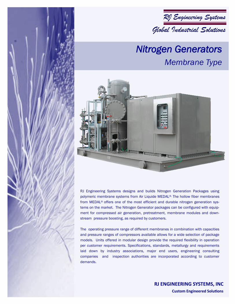
RJ Engineering Systems designs and builds Nitrogen Generation Packages using
polymeric membrane systems from Air Liquide MEDAL®. The hollow fiber membranes
from MEDAL® offers one of the most efficient and durable nitrogen generation sys-
tems on the market. The Nitrogen Generator packages can be configured with equip-
ment for compressed air generation, pretreatment, membrane modules and down-
stream pressure boosting, as required by customers.
The operating pressure range of different membranes in combination with capacities
and pressure ranges of compressors available allows for a wide selection of package
models. Units offered in modular design provide the required flexibility in operation
per customer requirements. Specifications, standards, metallurgy and requirements
laid down by industry associations, major end users, engineering consulting
companies and inspection authorities are incorporated according to customer
demands.
Custom Engineered Solutions
RJ ENGINEERING SYSTEMS, INC
Nitrogen Generators
Membrane Type
MEDAL® hollow fiber nitrogen membranes are the most advanced in the world. The superior
performance of MEDAL® nitrogen membranes is derived from their high selectivity and high
productivity, which are a result of the ability to produce nitrogen membranes with an extremely
thin, defect free separating layer.
The range of MEDAL® membranes available have an output range of 5 to 5000 l/min and purities
of 95 to 99.95%, dry and CO2 free .
Nitrogen Generators using MEDAL membrane separators are typically of the composite type and
are more compact in size than those utilizing alternate technologies. This is a result of higher
nitrogen production per unit volume of membrane module. After aging of the membranes, the
nitrogen recovery ratio remains the same, with drop in production volume per membrane, at the
same time contributing to reduction in pressure drop across the membrane. The packaged units
are always sized to accommodate for the reduction in production volume after aging.
Membranes from MEDAL can tolerate high water content in the feed air. The membrane separator
performance will not decline permanently should water condense on the membrane surface.
Their performance reverts to 100% once the condensed water has dried.
The high H2O and CO2 permeability of the membranes ensures a very dry (-70 °C pressure dew
point) nitrogen product, depleted of CO2.
Membranes separate gases by the principle of selective permeation across the membrane wall.
For polymeric membranes, the rate of permeation of each gas is determined by its solubility in the
membrane material, and the rate of diffusion through the molecular free volume in the membrane
wall. Gases that exhibit high solubility in the membrane and gases that are small in molecular
size, permeate faster than larger, less soluble gases.
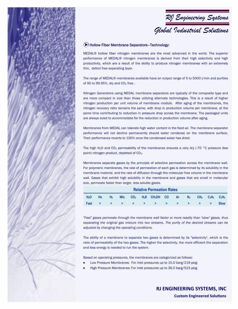
"Fast" gases permeate through the membrane wall faster or more readily than "slow" gases, thus
separating the original gas mixture into two streams. The purity of the desired streams can be
adjusted by changing the operating conditions.
The ability of a membrane to separate two gases is determined by its "selectivity", which is the
ratio of permeability of the two gases. The higher the selectivity, the more efficient the separation
and less energy is needed to run the system.
Based on operating pressures, the membranes are categorized as follows:
Low Pressure Membranes: For inlet pressures up to 15.0 barg/219 psig
High Pressure Membranes: For inlet pressures up to 36.0 barg/523 psig
RJ ENGINEERING SYSTEMS, INC
Custom Engineered Solutions
Relative Permeation Rates
H2O He H2 NH3 CO2 H2S CH3OH CO Ar N2 CH4 C2H6 C3H8
Fast > > > > > > > > > > > Slow
Hollow Fiber Membrane Separators–Technology:
Compressed air supply to the Nitrogen generator is pretreated through a customized train,
depending on the quality of the compressed air. Wet compressed air from Oil flooded or lubricated
compressors go through a bulk coalescing filter to remove free water and oil droplets, followed by
a preheater to stabilize the relative humidity to 90% or less, to avoid wetting of the downstream
equipment. The heater is also designed to maintain an optimum process temperature conducive
to maximum recovery rates and flow capacity. An Activated carbon bed filter removes oil aerosols
and vapor, with a 0.1 micron particulate filter downstream of heater to ensure long uninterrupted
life of the membranes.
Pretreatment systems for compressed air supplied from oil free compressors can be limited to a
coalescing filter and heater. Activated carbon filters are not needed unless ingress of
hydrocarbon vapors are anticipated.
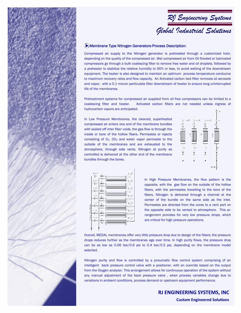
In Low Pressure Membranes, the cleaned, superheated
compressed air enters one end of the membrane bundles
with sealed off inter fiber voids, the gas flow is through the
inside or bore of the hollow fibers. Permeates or rejects
consisting of O2, CO2 and water vapor permeate to the
outside of the membranes and are exhausted to the
atmosphere, through side vents. Nitrogen at purity as
controlled is delivered at the other end of the membrane
bundles through the bores.
In High Pressure Membranes, the flow pattern is the
opposite, with the gas flow on the outside of the hollow
fibers, with the permeates travelling to the bore of the
fibers. Nitrogen is delivered through a channel at the
center of the bundle on the same side as the inlet.
Permeates are directed from the cores to a vent port on
the opposite side to be vented to atmosphere. This ar-
rangement provides for very low pressure drops, which
are critical for high pressure operations.
Overall, MEDAL membranes offer very little pressure drop due to design of the fibers; the pressure
drops reduces further as the membranes age over time. In high purity flows, the pressure drop
can be as low as 0.06 bar/0.9 psi to 0.4 bar/5.5 psi, depending on the membrane model
selected.
Nitrogen purity and flow is controlled by a pneumatic flow control system comprising of an
intelligent back pressure control valve with a positioner, with an override based on the output
from the Oxygen analyzer. This arrangement allows for continuous operation of the system without
any manual adjustment of the back pressure valve , when process variables change due to
variations in ambient conditions, process demand or upstream equipment performance.
RJ ENGINEERING SYSTEMS, INC
Custom Engineered Solutions
Membrane Type Nitrogen Generators-Process Description:
Membrane Type Nitrogen Generators are designed to operate continuously at maximum design
rate but can seamlessly adapt to fluctuating demands across the full range. If the demand goes
down, the system shuts off the inlet gas flow at an adjustable discharge pressure set point until
the demand picks up again; the nitrogen supply resumes immediately on demand.
The modular construction allows modifying the capacity of the system by isolation of one or more
membrane bundles, if needed to adjust the real time size of the unit. This feature allows online
replacement of the bundles as well, without affecting production.
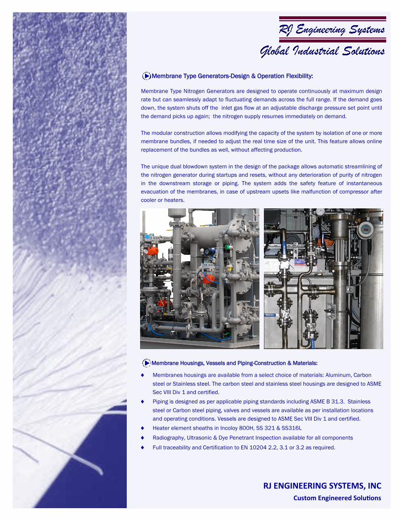
The unique dual blowdown system in the design of the package allows automatic streamlining of
the nitrogen generator during startups and resets, without any deterioration of purity of nitrogen
in the downstream storage or piping. The system adds the safety feature of instantaneous
evacuation of the membranes, in case of upstream upsets like malfunction of compressor after
cooler or heaters.
RJ ENGINEERING SYSTEMS, INC
Custom Engineered Solutions
Membranes housings are available from a select choice of materials: Aluminum, Carbon
steel or Stainless steel. The carbon steel and stainless steel housings are designed to ASME
Sec VIII Div 1 and certified.
Piping is designed as per applicable piping standards including ASME B 31.3. Stainless
steel or Carbon steel piping, valves and vessels are available as per installation locations
and operating conditions. Vessels are designed to ASME Sec VIII Div 1 and certified.
Heater element sheaths in Incoloy 800H, SS 321 & SS316L
Radiography, Ultrasonic & Dye Penetrant Inspection available for all components
Full traceability and Certification to EN 10204 2.2, 3.1 or 3.2 as required.
Membrane Type Generators-Design & Operation Flexibility:
Membrane Housings, Vessels and Piping-Construction & Materials:
Special Features :
RJ ENGINEERING SYSTEMS, INC
Custom Engineered Solutions
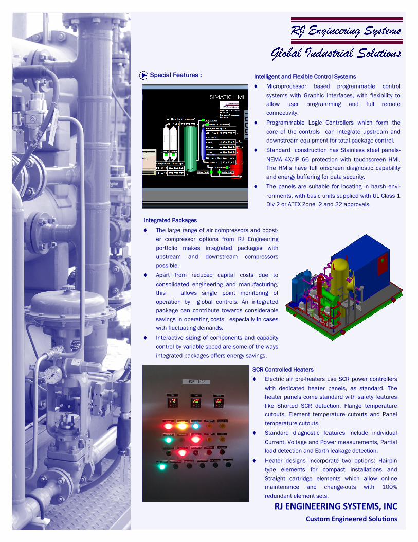
Intelligent and Flexible Control Systems
Microprocessor based programmable control
systems with Graphic interfaces, with flexibility to
allow user programming and full remote
connectivity.
Programmable Logic Controllers which form the
core of the controls can integrate upstream and
downstream equipment for total package control.
Standard construction has Stainless steel panels-
NEMA 4X/IP 66 protection with touchscreen HMI.
The HMIs have full onscreen diagnostic capability
and energy buffering for data security.
The panels are suitable for locating in harsh envi-
ronments, with basic units supplied with UL Class 1
Div 2 or ATEX Zone 2 and 22 approvals.
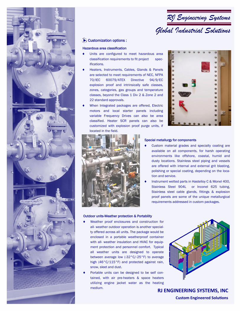
SCR Controlled Heaters
Electric air pre-heaters use SCR power controllers
with dedicated heater panels, as standard. The
heater panels come standard with safety features
like Shorted SCR detection, Flange temperature
cutouts, Element temperature cutouts and Panel
temperature cutouts.
Standard diagnostic features include individual
Current, Voltage and Power measurements, Partial
load detection and Earth leakage detection.
Heater designs incorporate two options: Hairpin
type elements for compact installations and
Straight cartridge elements which allow online
maintenance and change-outs with 100%
redundant element sets.
Integrated Packages
The large range of air compressors and boost-
er compressor options from RJ Engineering
portfolio makes integrated packages with
upstream and downstream compressors
possible.
Apart from reduced capital costs due to
consolidated engineering and manufacturing,
this allows single point monitoring of
operation by global controls. An integrated
package can contribute towards considerable
savings in operating costs, especially in cases
with fluctuating demands.
Interactive sizing of components and capacity
control by variable speed are some of the ways
integrated packages offers energy savings.
Customization options :
RJ ENGINEERING SYSTEMS, INC
Custom Engineered Solutions
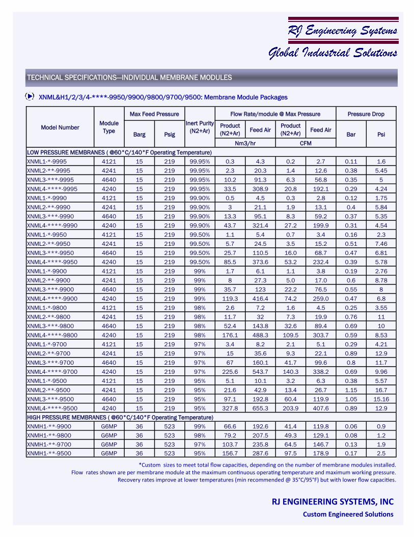
Hazardous area classification
Units are configured to meet hazardous area
classification requirements to fit project spec-
ifications.
Heaters, Instruments, Cables, Glands & Panels
are selected to meet requirements of NEC, NFPA
70/IEC 60079/ATEX Directive 94/9/EC
explosion proof and intrinsically safe classes,
zones, categories, gas groups and temperature
classes, beyond the Class 1 Div 2 & Zone 2 and
22 standard approvals.
When Integrated packages are offered, Electric
motors and local starter panels including
variable Frequency Drives can also be area
classified. Heater SCR panels can also be
customized with explosion proof purge units, if
located in the field.
Outdoor units-Weather protection & Portability
Weather proof enclosures and construction for
all- weather outdoor operation is another special-
ty offered across all units. The package would be
enclosed in a portable weatherproof container
with all- weather insulation and HVAC for equip-
ment protection and personnel comfort. Typical
all weather units are designed to operate
between average low (-32°C/-25°F) to average
high (46°C/115°F) and protected against rain,
snow, sleet and dust.
Portable units can be designed to be self con-
tained, with air pre-heaters & space heaters
utilizing engine jacket water as the heating
medium.
Special metallurgy for components
Custom material grades and specialty coating are
available on all components, for harsh operating
environments like offshore, coastal, humid and
dusty locations. Stainless steel piping and vessels
are offered with internal and external grit blasting,
polishing or special coating, depending on the loca-
tion and service.
Instrument wetted parts in Hastelloy C & Monel 400,
Stainless Steel 904L or Inconel 625 tubing,
Stainless steel cable glands, fittings & explosion
proof panels are some of the unique metallurgical
requirements addressed in custom packages.
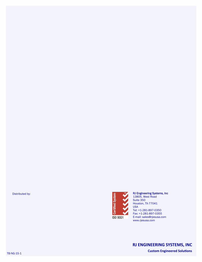
XNML&H1/2/3/4-****-9950/9900/9800/9700/9500: Membrane Module Packages
TECHNICAL SPECIFICATIONS—INDIVIDUAL MEMBRANE MODULES
RJ ENGINEERING SYSTEMS, INC
Custom Engineered Solutions
*Custom sizes to meet total flow capacities, depending on the number of membrane modules installed. Flow rates shown are per membrane module at the maximum continuous operating temperature and maximum working pressure.
Recovery rates improve at lower temperatures (min recommended @ 35°C/95°F) but with lower flow capacities.
Model Number Module
Type
Max Feed Pressure
Inert Purity
(N2+Ar)
Flow Rate/module @ Max Pressure Pressure Drop
Barg Psig
Product
(N2+Ar) Feed Air
Product
(N2+Ar) Feed Air
Bar Psi
Nm3/hr CFM
LOW PRESSURE MEMBRANES ( @60°C/140°F Operating Temperature)
XNML1-*-9995 4121 15 219 99.95% 0.3 4.3 0.2 2.7 0.11 1.6
XNML2-**-9995 4241 15 219 99.95% 2.3 20.3 1.4 12.6 0.38 5.45
XNML3-***-9995 4640 15 219 99.95% 10.2 91.3 6.3 56.8 0.35 5
XNML4-****-9995 4240 15 219 99.95% 33.5 308.9 20.8 192.1 0.29 4.24
XNML1-*-9990 4121 15 219 99.90% 0.5 4.5 0.3 2.8 0.12 1.75
XNML2-**-9990 4241 15 219 99.90% 3 21.1 1.9 13.1 0.4 5.84
XNML3-***-9990 4640 15 219 99.90% 13.3 95.1 8.3 59.2 0.37 5.35
XNML4-****-9990 4240 15 219 99.90% 43.7 321.4 27.2 199.9 0.31 4.54
XNML1-*-9950 4121 15 219 99.50% 1.1 5.4 0.7 3.4 0.16 2.3
XNML2-**-9950 4241 15 219 99.50% 5.7 24.5 3.5 15.2 0.51 7.46
XNML3-***-9950 4640 15 219 99.50% 25.7 110.5 16.0 68.7 0.47 6.81
XNML4-****-9950 4240 15 219 99.50% 85.5 373.6 53.2 232.4 0.39 5.78
XNML1-*-9900 4121 15 219 99% 1.7 6.1 1.1 3.8 0.19 2.76
XNML2-**-9900 4241 15 219 99% 8 27.3 5.0 17.0 0.6 8.78
XNML3-***-9900 4640 15 219 99% 35.7 123 22.2 76.5 0.55 8
XNML4-****-9900 4240 15 219 99% 119.3 416.4 74.2 259.0 0.47 6.8
XNML1-*-9800 4121 15 219 98% 2.6 7.2 1.6 4.5 0.25 3.55
XNML2-**-9800 4241 15 219 98% 11.7 32 7.3 19.9 0.76 11
XNML3-***-9800 4640 15 219 98% 52.4 143.8 32.6 89.4 0.69 10
XNML4-****-9800 4240 15 219 98% 176.1 488.3 109.5 303.7 0.59 8.53
XNML1-*-9700 4121 15 219 97% 3.4 8.2 2.1 5.1 0.29 4.21
XNML2-**-9700 4241 15 219 97% 15 35.6 9.3 22.1 0.89 12.9
XNML3-***-9700 4640 15 219 97% 67 160.1 41.7 99.6 0.8 11.7
XNML4-****-9700 4240 15 219 97% 225.6 543.7 140.3 338.2 0.69 9.96
XNML1-*-9500 4121 15 219 95% 5.1 10.1 3.2 6.3 0.38 5.57
XNML2-**-9500 4241 15 219 95% 21.6 42.9 13.4 26.7 1.15 16.7
XNML3-***-9500 4640 15 219 95% 97.1 192.8 60.4 119.9 1.05 15.16
XNML4-****-9500 4240 15 219 95% 327.8 655.3 203.9 407.6 0.89 12.9
HIGH PRESSURE MEMBRANES ( @60°C/140°F Operating Temperature)
XNMH1-**-9900 G6MP 36 523 99% 66.6 192.6 41.4 119.8 0.06 0.9
XNMH1-**-9800 G6MP 36 523 98% 79.2 207.5 49.3 129.1 0.08 1.2
XNMH1-**-9700 G6MP 36 523 97% 103.7 235.8 64.5 146.7 0.13 1.9
XNMH1-**-9500 G6MP 36 523 95% 156.7 287.6 97.5 178.9 0.17 2.5
RJ Engineering Systems, Inc
13805, West Road
Suite 350
Houston, TX-77041
USA
Tel: +1-281-897-0350
Fax: +1-281-897-0355
E-mail: [email protected]
www.rjesusa.com
RJ ENGINEERING SYSTEMS, INC
Custom Engineered Solutions
Distributed by:
TB-NG-15-1