nitim: a new metrology machine for targets with · pdf filetargets with highly variable...
TRANSCRIPT

NITIM: A NEW METROLOGY MACHINE FOR TARGETS WITH HIGHLY VARIABLE GEOMETRIES
20th Target Fabrication Meeting May 23, 2012
B.L. Lawson, R.C. Montesanti, S. Edson, J. Horner, M. Witte, P. Di Nicola, D. Kalantar, R. Wallace, J. Hughes, N. Antipa (Lawrence Livermore National Laboratory), B.F. Heidl, S. Vonhof, F. Howland (Akima Infrastructure Services, LLC), and S. Ludwick (Aerotech, Inc.)

Outline
• Background and Motivation • Description of Machine • Precision Engineering Design Principles
— Error budget — Lumped mass dynamic model — Robust manual tip-tilt stage
• Measured Performance
• Summary 20th Target Fabrication Meeting – Santa Fe, New Mexico 2

Outline
• Background and Motivation • Description of Machine • Precision Engineering Design Principles
— Error budget — Lumped mass dynamic model — Robust manual tip-tilt stage
• Measured Performance
• Summary 20th Target Fabrication Meeting – Santa Fe, New Mexico 3

4
TARGET: ASSEMBLY WITH TENS μm TOLERANCES
1. PHYSICS PACKAGE Central focus of experiment
e.g. hohlraums, capsules, foams, laser alignment artifacts, etc.
2. PERIPHERALS Components that support experiment
e.g. shields, backlighters
3. MOUNTING BASE Interfaces with the chamber’s target positioner
PURPOSE • Fusion research • High energy density physics research • Basic science (astrophysics and materials science)

Target alignment to the laser is crucial
for experiment success and not
damaging the system
Correct spacing and alignment of the target components relative to one-another is also crucial
Target alignment to the laser is crucial
for experiment success and not
damaging the system
5
EXTREMELY HIGH POWER LASER BEAMS IRRADIATE THE TARGET

CHARACTERIZING TARGETS AS SEEN FROM PORTS ON THE CHAMBER IS NECESSARY
Verify alignment of peripherals to physics package
Verify angle and offset of peripherals from physics package
Verify orientation of components to
diagnostic ports
Verify that shields are correctly positioned to protect sensitive diagnostics

7
Powell Scope was too small for NIF Targets
• Powell Scope is a successful, but small 5-axis optical measuring machine that the NITIM was designed to replace.
• NIF Target Peripherals (e.g backlighters and shields) further from target chamber center (TCC)
— NIF Targets: ±50mm — Powell Scope range: ±12.5mm
from TCC
• NIF target length: — NIF: 170mm from base to TCC — Powell Scope: ≤92mm
20th Target Fabrication Meeting – Santa Fe, New Mexico
8
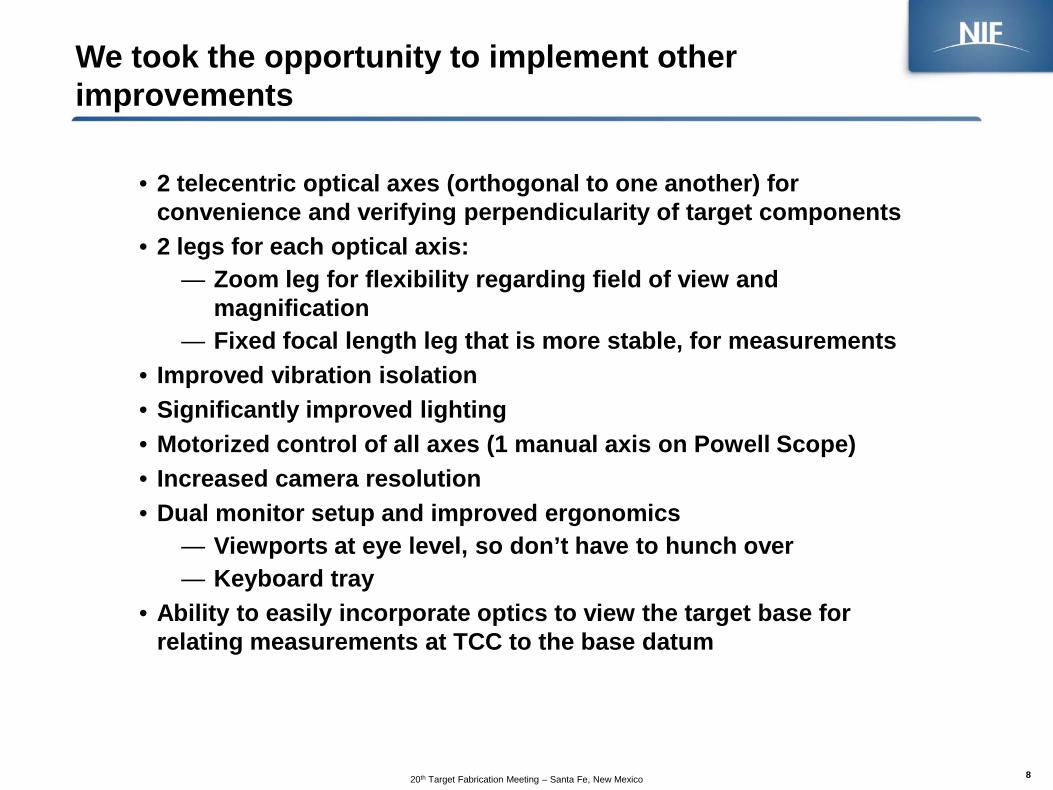
We took the opportunity to implement other improvements
• 2 telecentric optical axes (orthogonal to one another) for convenience and verifying perpendicularity of target components
• 2 legs for each optical axis: — Zoom leg for flexibility regarding field of view and
magnification — Fixed focal length leg that is more stable, for measurements
• Improved vibration isolation • Significantly improved lighting • Motorized control of all axes (1 manual axis on Powell Scope) • Increased camera resolution • Dual monitor setup and improved ergonomics
— Viewports at eye level, so don’t have to hunch over — Keyboard tray
• Ability to easily incorporate optics to view the target base for relating measurements at TCC to the base datum
20th Target Fabrication Meeting – Santa Fe, New Mexico

Outline
• Background and Motivation • Description of Machine • Precision Engineering Design Principles
— Error budget — Lumped mass dynamic model — Robust manual tip-tilt stage
• Measured Performance
• Summary 20th Target Fabrication Meeting – Santa Fe, New Mexico 9
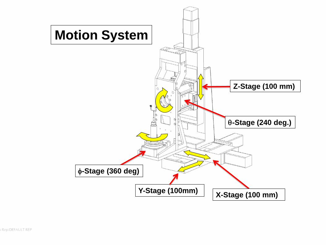
Y-Stage (100mm) X-Stage (100 mm)
φ-Stage (360 deg)
Z-Stage (100 mm)
θ-Stage (240 deg.)
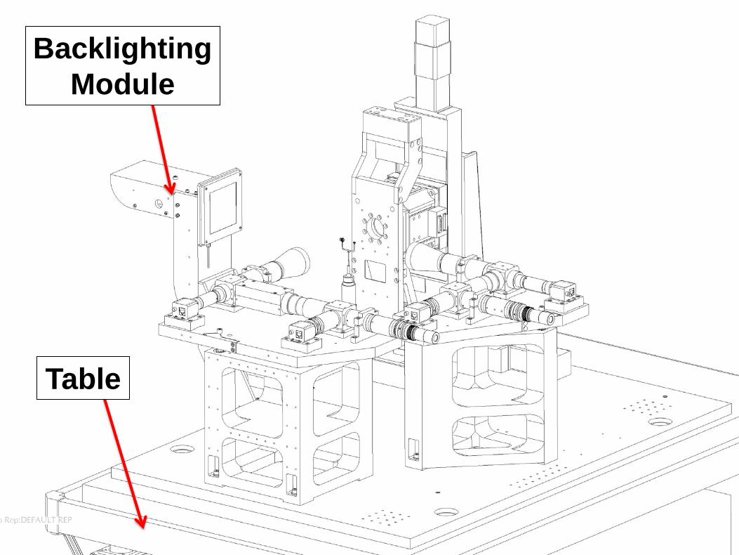
Motion System


Base Plate

Front Optics Support Frame
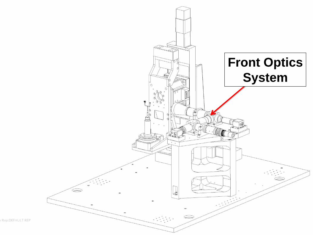
Front Optics System
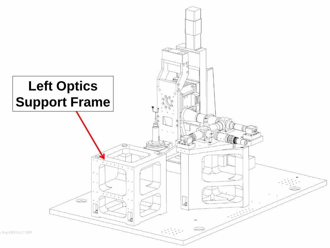
Left Optics Support Frame

Left Optics System
17 26th American Society for Precision Engineering Meeting – Denver, Colorado
Backlighting Module
Table
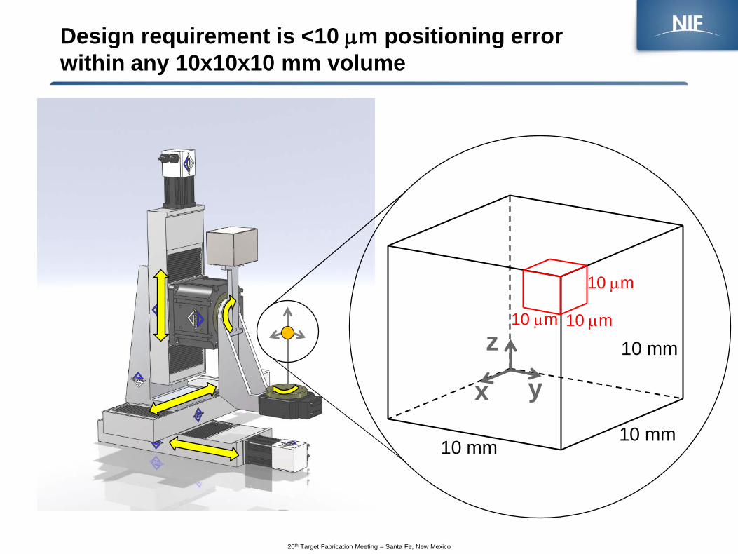
10 µm 10 µm
10 µm
10 mm
10 mm 10 mm
x y
z
Design requirement is <10 µm positioning error within any 10x10x10 mm volume
20th Target Fabrication Meeting – Santa Fe, New Mexico

Each optical axis has a fixed focal length camera, and a zoom leg to a camera and eyepiece
19
• Zoom leg is used for orientation and viewing fine details, but image moves on camera as the zoom is changed
• Fixed leg provides a measurement datum
Telecentric Lens
Fixed Focal Length Leg
Beam Splitter
Zoom Optics
Beam Splitter
Eyepiece Camera
Camera
Front Optical Axis
20th Target Fabrication Meeting – Santa Fe, New Mexico
20
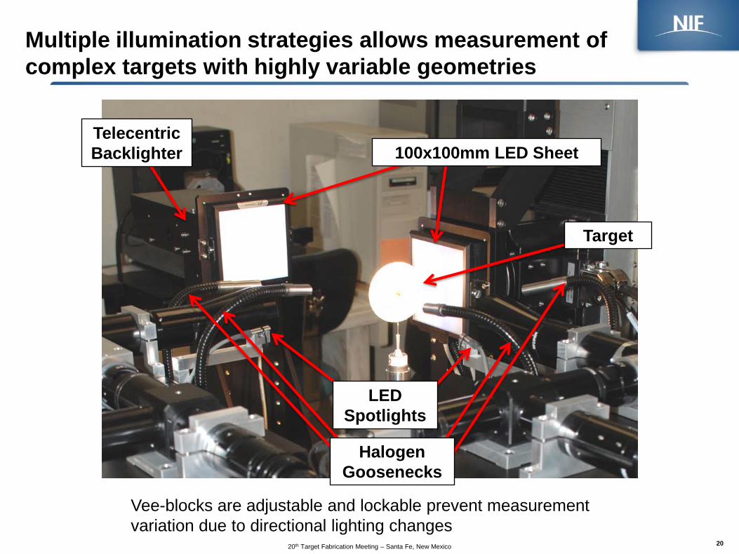
Multiple illumination strategies allows measurement of complex targets with highly variable geometries
20th Target Fabrication Meeting – Santa Fe, New Mexico
100x100mm LED Sheet Telecentric Backlighter
Halogen Goosenecks
Vee-blocks are adjustable and lockable prevent measurement variation due to directional lighting changes
LED Spotlights
Target

Outline
• Background and Motivation • Description of Machine • Precision Engineering Design Principles
— Error budget — Lumped mass dynamic model — Robust manual tip-tilt stage
• Measured Performance
• Summary 20th Target Fabrication Meeting – Santa Fe, New Mexico 21
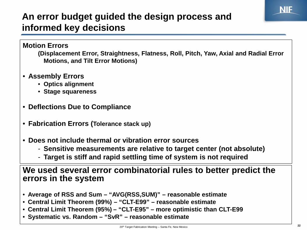
An error budget guided the design process and informed key decisions
22 20th Target Fabrication Meeting – Santa Fe, New Mexico
Motion Errors (Displacement Error, Straightness, Flatness, Roll, Pitch, Yaw, Axial and Radial Error
Motions, and Tilt Error Motions)
• Assembly Errors • Optics alignment • Stage squareness
• Deflections Due to Compliance
• Fabrication Errors (Tolerance stack up)
• Does not include thermal or vibration error sources
- Sensitive measurements are relative to target center (not absolute) - Target is stiff and rapid settling time of system is not required
We used several error combinatorial rules to better predict the errors in the system • Average of RSS and Sum – “AVG(RSS,SUM)” – reasonable estimate • Central Limit Theorem (99%) – “CLT-E99” – reasonable estimate • Central Limit Theorem (95%) – “CLT-E95” – more optimistic than CLT-E99 • Systematic vs. Random – “SvR” – reasonable estimate

The error budget identified the worst error culprits and we used that information to guide design decisions
Predicted error in the X-direction from a 10 mm move in XYZ and 180° move in θ and φ
AVG (RSS,SUM)
CLT –
E99%
CLT –
E95% SvR
δx (µm) 33 28 19 29
δy (µm)
25 25 17 21
δz (µm)
21 22 15 17
Error budget was used to: 1. Define minimum required
stage accuracy
2. Define required tolerances of fabricated parts
3. Predict performance of completed system
20th Target Fabrication Meeting – Santa Fe, New Mexico

24
Z
X Y
X-stage
Z-stage motor
Z-stage
Angle Bracket
Θ-stage
Arm, CB, φ-stage
KT,x KT,z
KT,y
X-stage motor
• Fast and intuitive estimate of the low mode rotational natural frequencies of the system
• Assumes rigid components and connections
• Combines all of the masses and positions into an equivalent mass and moment of inertia
A simple lumped mass dynamic model informed stage selection and predicted expected resonances

25
The lumped mass dynamic model helped guide design decisions and predict the performance of the system
Conservative Estimate (Less Stiff) about x-axis
about y-axis
about z-axis
Natural frequency at θ-stage (Hz) 83 0 227 Natural frequency at Z-stage (Hz) 60 94 89 Natural frequency at X-stage (Hz) 25 27 79 Natural frequency at Y-stage(Hz) 23 24 64
20th Target Fabrication Meeting – Santa Fe, New Mexico
The lumped mass model helped us determine that relatively little dynamic performance was gained by using significantly more expensive stages.
About x-axis About y-axis About z-axis
Y-stage fn (Hz) 54 - -
Lowest natural frequency as measured by the feedback controller:

3 aluminum clamps, each with 3 rounded feet , secure the optics to the frame
26
Manual tip-tilt stages were designed to align vision systems to motion system
Tip-Tilt Actuators (3 Screws):
• Spherical bearing surface • 0.75” Diameter >20 kg
load limit
40TPI
Adjust tip-tilt with wrench or hex driver
440 SST, 55 HRC
SST, 58 HRC, ultrafine grain
3 Bal-Tec V-Grooves
20th Target Fabrication Meeting – Santa Fe, New Mexico

27
The tip-tilt optics alignment stages used precision engineering principles to meet the design requirements.
200 mm
Decoupled tip and tilt motions
• 6 µm optical resolution over 100 mm total travel 60 µrad optics alignment requirement
• 40 TPI pitch, 200 mm distance, and 5° resolution <45 µrad resolution
Flexures lock tip-tilt actuators
“Cookie bite” in plate thread gives 3-jaw chuck clamping
20th Target Fabrication Meeting – Santa Fe, New Mexico
Outline
• Background and Motivation • Description of Machine • Precision Engineering Design Principles
— Error budget — Lumped mass dynamic model — Robust manual tip-tilt stage
• Measured Performance
• Summary 20th Target Fabrication Meeting – Santa Fe, New Mexico 28
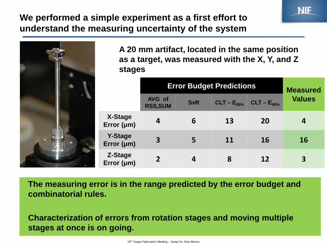
A 20 mm artifact, located in the same position as a target, was measured with the X, Y, and Z stages
We performed a simple experiment as a first effort to understand the measuring uncertainty of the system
20th Target Fabrication Meeting – Santa Fe, New Mexico
The measuring error is in the range predicted by the error budget and combinatorial rules. Characterization of errors from rotation stages and moving multiple stages at once is on going.
Error Budget Predictions Measured Values AVG of
RSS,SUM SvR CLT – E95% CLT – E99%
X-Stage Error (μm) 4 6 13 20 4
Y-Stage Error (μm) 3 5 11 16 16
Z-Stage Error (μm) 2 4 8 12 3

Summary
30
• A new 5-axis machine was designed and built to characterize targets for high-energy lasers
• Precision engineering principles that rely on determinism were used to guide the design
• The performance of the machine is consistent with the predictions of the design tools
20th Target Fabrication Meeting – Santa Fe, New Mexico

Questions?
31 20th Target Fabrication Meeting – Santa Fe, New Mexico