nirs himac cancer treatment by charged particles -...
TRANSCRIPT

HIMAC
NIRS
Cancer Treatment by Charged Particles
- Carbon Ion Radiotherapy – Part 2
HIMAC
NIRS
Takeshi Murakami Research Center of Charged Particle Therapy
National Institute of Radiological Sciences
2012.07.04-5

HIMAC
NIRS
Medical application of accelerators
Requirements
1. Stable, reliable, easy operation and maintenance
• Ion source, injector, main ring, irradiation system etc.
(same way as water from a faucet…)
2. Precise irradiation system
• Patient positioning
• Respiration motion compensation
3. Small inexpensive facility!
• accelerators
• Irradiation system
Satisfied!
???

HIMAC
NIRS
Design Consideration for Compact Facility
What Ion Species? Carbon!
1. Scanning or Broadbeam?
2. How high the Energy ?
3. How large the Irradiation-Field Size?
4. How high the Intensity?
5. Consequently, how large the Facility?
Based on experience at HIMAC, the specification is determined!!

HIMAC
NIRS
How high a beam energy should be?
Residual range of 250 mm covers almost all treatments at HIMAC.
Required energy: 400 MeV/n, with an additional range of 25 mm required for the scatterer etc.
0
100
200
300
400
500
600
700
800
900
~20 80~100 160~180 240~260
Residual Range (mm)
Head&Neck
Brain
Lacrimal gland
Esophagus
Lung
Linver
Pancreas
Bone&SoftTissu
Prostate
Uterus
Digestive duct
Others

HIMAC
NIRS
How large a field size should be?
The field of 200 mm in diameter is large enough to cover almost all treatments in HIMAC.
0
100
200
300
400
500
600
700
800
900
~10 60~70 120~130 180~190
Field Diameter (mm)
Head&Neck
Brain
Lacrimal gland
Esophagus
Lung
Linver
Pancreas
Bone&SoftTissu
Prostate
Uterus
Digestive duct
Others
0
100
200
300
400
500
600
700
800
900
10~20 60~70 110~120
SOBP Size (mm)
Head&Neck
Brain
Lacrimal gland
Esophagus
Lung
Linver
Pancreas
Bone&SoftTissu
Prostate
Uterus
Digestive duct
Others
The SOBP with a depth of 150 mm covers treatments more than 95%.
HIMAC
NIRS
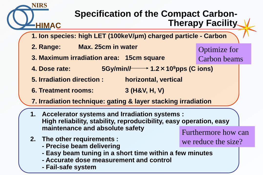
Specification of the Compact Carbon-Therapy Facility
1. Ion species: high LET (100keV/μm) charged particle - Carbon
2. Range: Max. 25cm in water
3. Maximum irradiation area: 15cm square
4. Dose rate: 5Gy/min/l 1.2×10⁹pps (C ions)
5. Irradiation direction : horizontal, vertical
6. Treatment rooms: 3 (H&V, H, V)
7. Irradiation technique: gating & layer stacking irradiation
1. Accelerator systems and Irradiation systems : High reliability, stability, reproducibility, easy operation, easy maintenance and absolute safety
2. The other requirements : - Precise beam delivering - Easy beam tuning in a short time within a few minutes - Accurate dose measurement and control - Fail-safe system
Furthermore how can
we reduce the size?
Optimize for
Carbon beams
HIMAC
NIRS
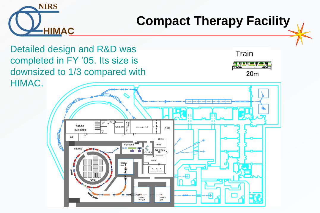
Compact Therapy Facility
Train Detailed design and R&D was
completed in FY ’05. Its size is
downsized to 1/3 compared with
HIMAC.

HIMAC
NIRS
Compact Injector Linac Cascade
An ECR ion source employs permanent magnets. The injector linac cascade consists of RFQ and APF-IH linac. The RFQ accelerates C4+ ions from 10 to 600 keV/n. The IH linac accelerates them to 4 MeV/n. The operation frequency is 200 MHz for both linacs.
APF IH-DTL

HIMAC
NIRS
Development of ECR source
Compact ECR ion source with all permanent magnets
1. Mirror magnetic field was copied from NIRS-ECR
2. Traveling-Wave-Tube amp. was chosen for fixed magnetic field
3. Enough insulation for carbon ion production
• Diameter 300mm
• Mirror field 0.87, 0.25, 0.59 T
• Permanent magnet NdFeB
• Max. surface field 1.1 T
• Microwave 8 - 10 GHz, 300 W
M. Muramatsu will contribute in ICIS05!

HIMAC
NIRS
Beam Test of Compact Injector
RFQ APF-IH
ECR
Analyzer
0
50
100
150
200
250
300
350
400
450
29.5 30 30.5 31 31.5 32 32.5 33
Pick-up voltage for IH-DTL (V)
FCN
2 (
eμ
A)
0
10
20
30
40
50
60
70
80
90
100
Tra
nsm
issi
on
(%
)
FC2
Transmission (%)
Kinetic energy distribution for 12
C4+
0
5
10
15
20
25
30
35
40
45
3.97 3.98 3.99 4 4.01 4.02 4.03
E (MeV/u)
dI/
dE (
arb
. u
nits)
0.44m

HIMAC
NIRS
Synchrotron
SXD
SXD
SXFr1
SXF
BMPf2
BMP1
SXDr1
BMP2
SM1 SM2
QD
ESD
BMPf1
BMP3
V-CR 6
H-CR 6
SXFr2
SXF
SXDr2
RF-KO
RF-Cavity
QF
H-CR 1
H-CR 2
H-CR 3
H-CR 5
V-CR 1
V-CR 2
V-CR 3
V-CR 4
H-CR 4
V-CR 5
ESI
BM
SM
QDS1
QDS2
DCCT
SPRN
FCN
Injection
Extraction
SXD
5m0
Lattice Type FODO
Maximum intensity of C6+ 1.2×10⁹ pps
Cell number 6
Long straight section 3.0m×6
Circumference 61.5m
Injection energy 4 MeV/u
Extraction energy 140 - 400 MeV/u
Revolution frequency 0.450 - 3.483 MHz
Emittance and Δp/p
of injection beam
10 π mm mrad
±0.2%
Acceptance
(after COD correction) 240/30 π mm mrad
Momentum acceptance ±0.4%
Qx /Qy 1.68-1.72/1.23
Maximum β function 11.5/13.4
transition gamma 1.72
ξx/ξy -0.5/-1.5
Shorten the straight line.
Specification

HIMAC
NIRS
Compact RF Cavity
Comparison between HIMAC cavity
HIMAC New cavity
Frequency [MHz] 1 ~ 8 0.4 ~ 7
Voltage [kV] 6 4.5
Power [kW] 15 8
Cavity size [cm] 277×89 150×140
Size of PS etc Amp. with Tetrode
70×40×60
250×150×250
70×70×90
Bias PS
100×100×200
Transister Amp.
60×85×220
Un-tuned RF cavity with Co-based MA

HIMAC
NIRS
Gunma University Heavy-Ion Medical Center

HIMAC
NIRS
Adjacent to Shin-Tosu Station
HIMAT
Shin-Tosu
To Fukuoka
To Kumamoto, Kagoshima
SAGA-HIMAT
To Saga, Nagasaki
Shin-Kansen Railway
near to Tosu high way junction Fukuoka
Tosu
HIMAC
NIRS
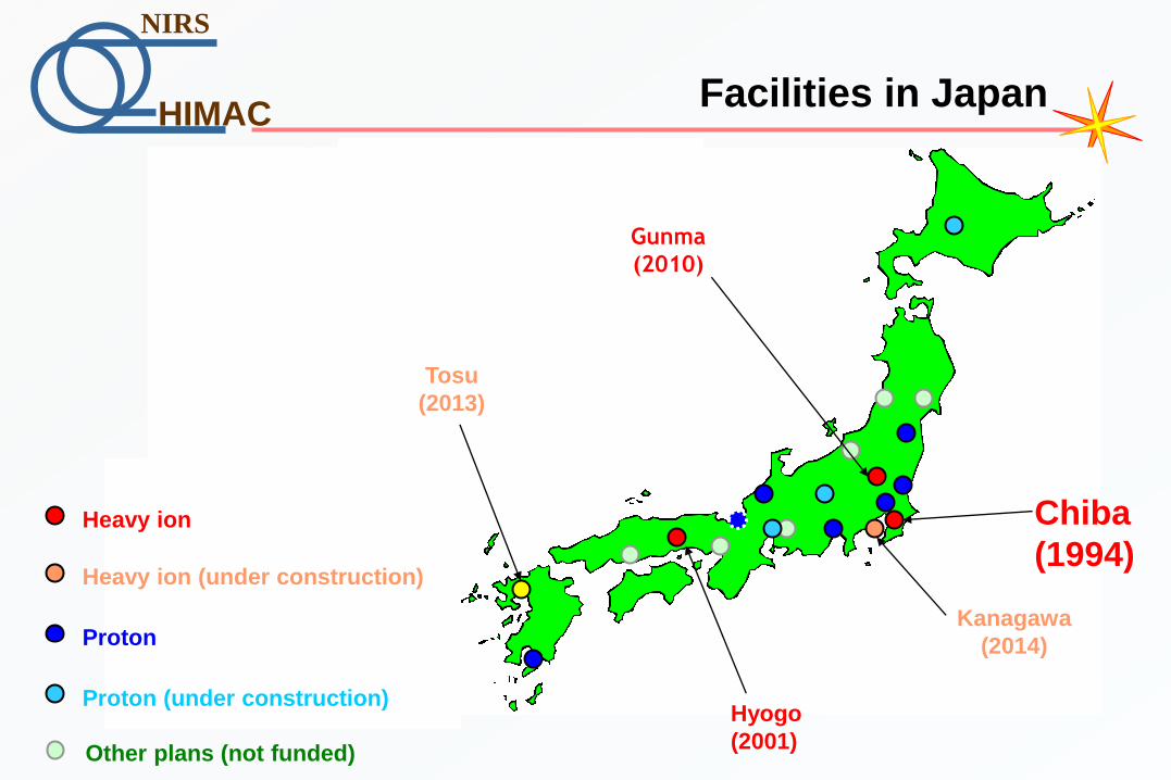
Facilities in Japan
Hyogo
(2001)
Chiba
(1994) Heavy ion
Heavy ion (under construction)
Proton
Proton (under construction)
Other plans (not funded)
Gunma
(2010)
Kanagawa
(2014)
Tosu
(2013)

HIMAC
NIRS
Heavy ion radiotherapy worldwide
Chiba
Gunma
Hyogo
Lanzhou
Busan
Darmstadt
Lyon
Wiener Neustadt
Pavia
Heidelberg
Rochester
Kanagawa Tosu
Shanghai
Heavy ion
Heavy ion (under construction)
Proton
Proton (under construction)
Heavy ion (planning)
Penang
Taipei

HIMAC
NIRS
Quick change of the target
840cc 69cc
(a) (b)
Change of target position and shape @PSI Large change of target size and shape
during the treatment process
Change the treatment planning, and bolus, collimator
-> 4-5 days are necessary for machining, transport, inspection

HIMAC
NIRS
Motivation of New Treatment Facility
1 day!
1 day treatment is possible
Adaptive Cancer Treatment
diagnosis and treatment in a short period

HIMAC
NIRS
scatterer
Patient collimator Bolus Ridge filter
Broad beam
Scanning
Wobbling magnets
Scanning magnets
range shifter
Irradiation Methods

HIMAC
NIRS
Comparison of scanning and broad beam method
Broad beam: matured
technology!
Scanning Broad beam
Dose distribution excellent good
Moving target No Yes
Irradiation time long short
Dose control Elaborate Easy
Bolus, collimator No Yes
Beam position < 0.2mm ~ 2 mm
Beam size Control No control
Intensity Low High
long treatment time
no moving target
sensitive to the device error
scanning
New scanning system must be
developed.

HIMAC
NIRS
100 120 140 160 180 200
-40
-20
0
20
40
Non-gating Gating
Gating with rescanning (8 times)
100 120 140 160 180 200
-40
-20
0
20
40
100 120 140 160 180 200
-40
-20
0
20
40
0
0.1
0.2
0.3
0.4
0.4
0.5
0.6
0.7
0.8
0.9
1.0
1.1
1.1
Motion:7mm in gate
Simulation of moving tumor irradiation
Irradiation on Moving Tumors
In order to avoid hot/cold spot due to
target motion, we decided to employ
“gating method” with rescanning.
Example:
Φ40mm
spherical target
stts 2,3/cos3.317.1)( 4

HIMAC
NIRS
R&S of Fast Scanning System
New control system
HIMAC SB course
Scanning
R&D port
1. Fast scanning system
2. Respiratory motion

HIMAC
NIRS
Fast Scanning
SMx
SMy
Beam
0.0
0.20.4
0.6
0.8
1.0
-50
0
50
0.0
0.2
0.4
0.6
0.8
1.0
0 200
-50
0
50
Example: B&ST
@Extended FT

HIMAC
NIRS
Operation pattern of synchrotron
0 200 400 600 800 1000 1200 1400 1600 1800 20000
10
20
30
40
50
60
nu
m.
of
po
rt
PTV (cc)
Manipulate synchrotron
1 spill (2×10¹⁰ particles) corresponds to 15
GyE on 300cc target!
-> Most of the treatments require 1 spill !
time
time
Fixed period
Extension of the flat-top
First half of 2006
300cc injection
acceleration
extraction
extraction
acceleration
injection

HIMAC
NIRS
Extension of the flat-top
0 10 20 30 40 50
0
2
4
-2
-1
0
1
2
0
1
2
3
4
Inte
nsity
Time (s)
Be
am
po
sitio
n (
mm
)
Horizontal
Vertical
Be
am
siz
e (
mm
)
Horizontal
Vertical
Size Position Intensity
Position, size , intensity -> stable?

HIMAC
NIRS
Scanning with extended Flat-Top
SMx
SMy
Beam
Syn. BM
Fluorescent screen
plan 1. Treatment planning for fast scanning ⇒ ×5
2. Modification of acc. operation ⇒ ×2
3. Fast scanning magnet ⇒ ×10
We can save the dead time of synchrotron operation.

HIMAC
NIRS
11-steps Energy Operation
1400
1200
1000
800
600
400
200
0300025002000150010005000
1150
1100
1050
1000200019001800170016001500
40ms
150ms
40ms
t (ms)
I(B
M)
(A)
11-step Energy: 430, 400, 380, 350, 320, 290, 260, 230, 200, 170 and 140
Tune: (Qh, Qv) = (3.68, 3.11)

HIMAC
NIRS
New Particle Therapy Research Facilities
○3D Scanning with Gating (H&V): 2 rooms
○Rotating Gantry : 1 room
Iso-center0 1 2m
SMxQM SMy
Monitors
RGF
RSF
Wall
PRN1 PRN2
9.0 m3D Scanning
New treatment facility
HIMAC building
Hospital
Research Building for Charged Particle Therapy

HIMAC
NIRS
Rotating Capsule
28 - 32GyE (1 fraction)
03/4 ~ 06/3 54 – 79.2GyE (9 fraction)
97/9 ~ 00/12
52.8 - 60GyE (4 fraction)
00/12 ~ 03/11
59.4 – 95.4GyE (18 fraction)
94/10 ~ 97/8
× burden on patients
× complicated treatment planning due to deformation
of organs
HIMAC
NIRS
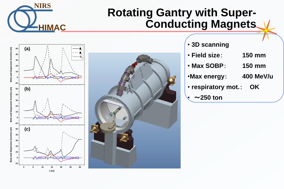
Rotating Gantry with Super-Conducting Magnets
-10
0
10
20
30
40
50
Beta
an
d d
isp
ers
ion
fu
ncti
on
(m
)
x
y
Dx
-10
0
10
20
30
40
50
Beta
an
d d
isp
ers
ion
fu
ncti
on
(m
)
0 5 10 15 20 25 30
-10
0
10
20
30
40
50
Beta
an
d d
isp
ers
ion
fu
ncti
on
(m
)
s (m)
(c)
(b)
(a)• 3D scanning
• Field size: 150 mm
• Max SOBP: 150 mm
•Max energy: 400 MeV/u
• respiratory mot.: OK
• ~250 ton

HIMAC
NIRS
New Particle Therapy Research Facilities
HIMAC
NIRS
New Particle Therapy Research Facilities 1F

HIMAC
NIRS
New Particle Therapy Research Facilities 1F
HIMAC
NIRS
New Particle Therapy Research Facilities 1F
HIMAC
NIRS
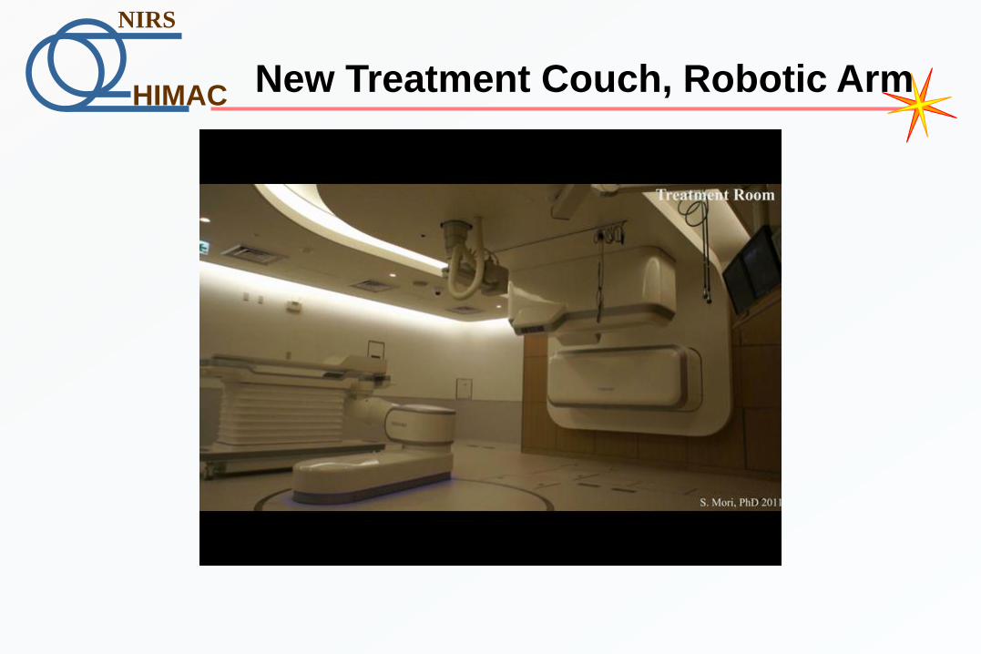
New Treatment Couch, Robotic Arm

HIMAC
NIRS
Requirements for the therapy at HIMAC
- Ion species: high LET (100keV/mm) charged particles
He, C, Ne, Si
- Range: 30cm in soft tissue 430MeV/u (C)
800MeV/u(Si)
- Maximum irradiation area: 22cm in diameter
- Dose rate: 5GyE/min 2×10⁹pps
- Beam direction: horizontal, vertical, etc...
-> “large accelerator”, being rare in the world
HIMAC
NIRS
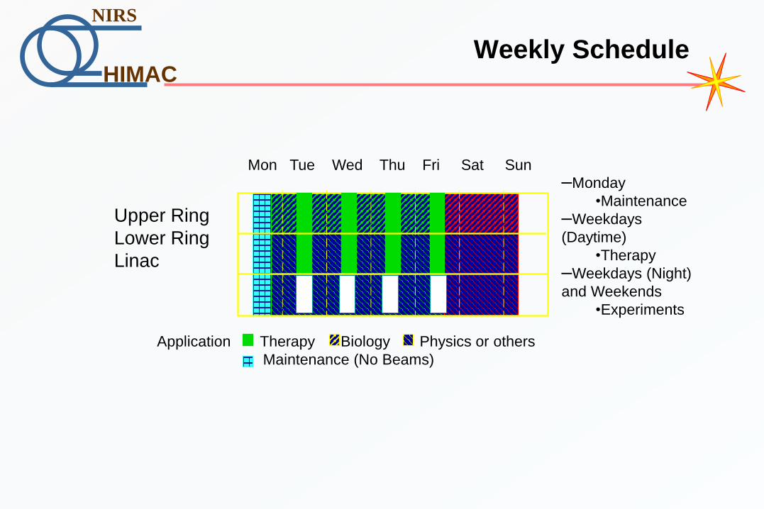
Weekly Schedule
–Monday
•Maintenance
–Weekdays
(Daytime)
•Therapy
–Weekdays (Night)
and Weekends
•Experiments
Mon Tue Wed Thu Fri Sat Sun
Upper Ring
Lower Ring
Linac
Application Therapy Biology Physics or others
Maintenance (No Beams)

HIMAC
NIRS
Specifications of the HIMAC facility
Ion source PIG, 10GHz-ECR, and
18GHz-ECR
8 keV/nucleon
Ion species: p to Xe
Injector RFQ linac (0.6 m f x 7.3 m long) 800 keV/ nucleon
Alvarez linac (2.2 m f x 24 m
long)
6 MeV/ nucleon
Main accelerator Synchrotron (42 m ) 2 rings 100 - 800 MeV / nucleon
repetition rate: 3.3 seconds
Irradiation rooms 3 treatment rooms
4 experiment rooms
Time Sharing Acceleration +
Pulse Magnets
General-physics experiment
room
Secondary beam experiment
room
Biology experiment room
Medium-energy experiment
room
2 experiment rooms
He to Ar
HIMAC
NIRS
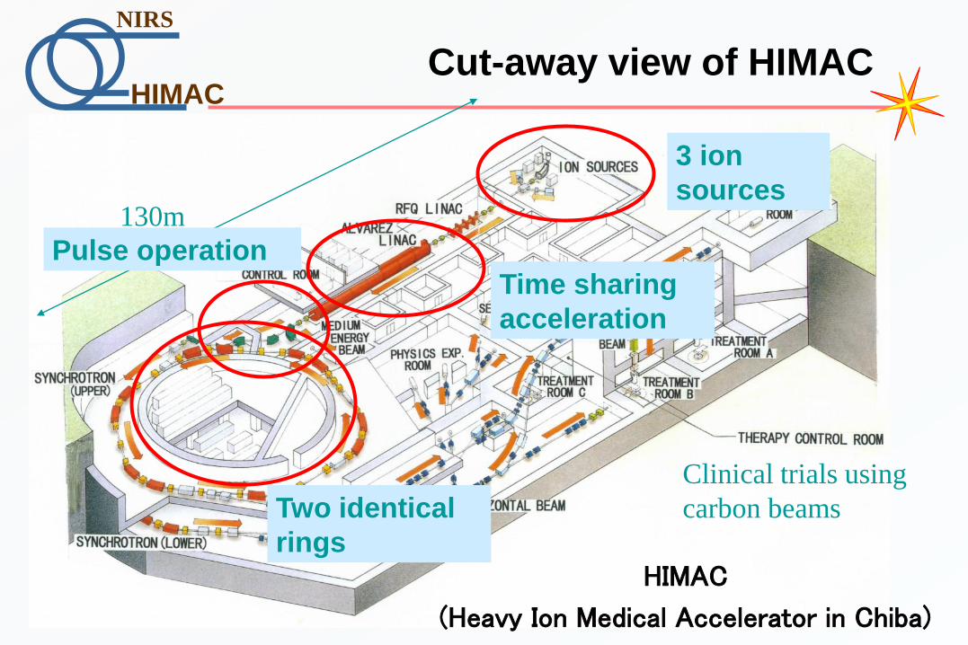
Cut-away view of HIMAC
HIMAC
(Heavy Ion Medical Accelerator in Chiba)
Clinical trials using
carbon beams
130m
3 ion
sources
Pulse operation
Time sharing
acceleration
Two identical
rings

HIMAC
NIRS
Experiment rooms (HIMAC B2F)
Secondary beam
experiment room
Medium-energy
experiment room
General-physics
experiment room
HIMAC
NIRS
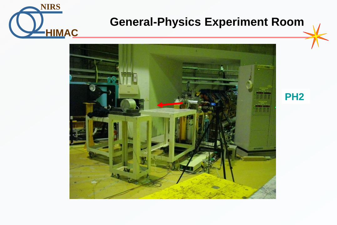
General-Physics Experiment Room
PH2

HIMAC
NIRS
Biology experiment room (HIMAC 2F)
Biology experiment room
HIMAC
NIRS
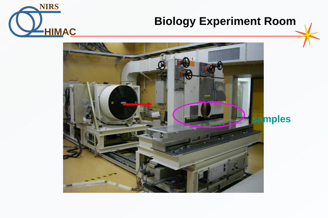
Biology Experiment Room
samples

HIMAC
NIRS
Time Sharing Acceleration
Injector
Upper
Ring
Lower
Ring
C Ar Xe
MEXP
Direct use
3.3sec

HIMAC
NIRS
The hours of operation, FY2011
0
1000
2000
3000
4000
5000
6000H
our
s in
FY20
11
Linac
Upper Ring
Lower Ring

HIMAC
NIRS
Beam Time for Physics and Biology
Cumulative time
0.0
1000.0
2000.0
3000.0
4000.0
5000.0
6000.0
1994 1997 2000 2003 2006 2009
Hours
in o
pera
tion
Year
Biology
Physics
HIMAC
NIRS
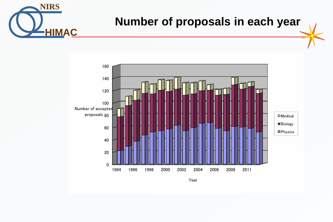
Number of proposals in each year
0
20
40
60
80
100
120
140
160
1994 1996 1998 2000 2002 2004 2006 2008 2011
Number of accepted
proposals
Year
Medical
Biology
Physics

HIMAC
NIRS
Number of Participants in the Basic Science Programs
0
100
200
300
400
500
600
700
800
1990 1995 2000 2005 2010 2015
Num
ber
of P
artici
pant
s
Outside users
Foreigners
Inside users