nirs ds2500 analyzernirs-instruments.com/pdf/manual for nirs ds2500 analyzer.pdfnirs . ds2500...
TRANSCRIPT

NIRS DS2500 Analyzer
Manual 8.922.8001EN


Metrohm AG CH-9100 Herisau Switzerland Phone +41 71 353 85 85 Fax +41 71 353 89 01 [email protected] www.metrohm.com
NIRS DS2500 Analyzer
Manual 8.922.8001EN 03.2013 fpe

Teachware Metrohm AG CH-9100 Herisau [email protected] This documentation is protected by copyright. All rights reserved.
Although all the information given in this documentation has been checked with great care, errors cannot be entirely excluded. Should you notice any mistakes please send us your comments using the address given above.

▪▪▪▪▪▪▪ 3
Change Control
Change control on this document is as follows:
Version Date Summary of Changes
1.0 December 2, 2012
Document first release, initiated change control
4 ▪▪▪▪▪▪▪
Table of contents
1 Introduction ................................................................................................................... 5 1.1 Information Disclaimer ................................................................................. 6
2 Hardware Familiarization .............................................................................................. 7 3 Specifications............................................................................................................... 12
3.1 Safety Certifications: .................................................................................. 12 3.2 Installation Parameters .............................................................................. 12 3.3 Electrical Specification ............................................................................... 13 3.4 Operating Specifications ............................................................................ 13 3.5 Mandatory Safety Notice ........................................................................... 13
4 Mounting Dimensions .................................................................................................. 14 5 Electrical Connection ................................................................................................... 15 6 Ethernet Connection .................................................................................................... 18 7 Connection to Vision Software .................................................................................... 20 8 DS2500 Diagnostics ..................................................................................................... 25
8.1 Performance Test ....................................................................................... 25 8.2 Instrument Calibration ............................................................................... 29 8.3 Wavelength Certification ............................................................................ 32 8.4 IPV Setup ................................................................................................... 35 8.5 Photometric Test ........................................................................................ 38
9 Sampling...................................................................................................................... 42 10 Maintenance .............................................................................................. 43
10.1 Instrument Cleanliness ............................................................................... 43 10.2 Lamp Replacement ..................................................................................... 43 10.3 Fan Filter Replacement ............................................................................... 49 10.4 Fuse Replacement ...................................................................................... 50

▪▪▪▪▪▪▪ 5
1 Introduction The DS2500 is a rugged, dedicated Near-Infrared Reflectance Analyzer, designed for the wavelength range from 400-2500 nanometers. This is an excellent region for sample analysis, containing information on molecular vibrations which can be measured easily with a low-noise, high-quality instrument.
The DS2500 instrument is based upon high-resolution dispersive grating technology. The detector array, composed of both Silicon and Lead Sulfide detectors, covers the full range of scanning. It offers excellent peak shape resolution, and offers comparable spectra to the Metrohm XDS Rapid Content Analyzer.
Common sampling methods are as follows:
• Reflectance cells positioned in the sample holder
• Vials, with proper holder
Housed in a robust cabinet, the analyzer is designed for easy, reliable placement at the desired location in the sampling area. Avoid vibration, drafts, and contaminants, including dust.
The DS2500 NIR Analyzer provides non-destructive analysis of chemical and pharmaceutical products using a reflectance sampling window, with a cover to avoid light contamination of sample spectra. Because most materials can be measured directly, with no need for sample dilution or preparation, the material can be measured as produced, with no loss of end product.
Operation of the DS2500 is through FOSS Vision™ software, which is robust, powerful, and easy to use. This validated software package meets all 21 CFR Part 11 requirements, and comes with a test script to prove compliance for internal regulatory personnel. Combined with normal customer procedures for network and user access, all 21 CFR Part 11 requirements are met.
Vision provides excellent tools by which to develop an analytical model for sample prediction. The NIR sample information is correlated with quantitative lab data from the primary analysis method, and a predictive model is used to report values for ongoing sample analysis.
Communication between instrument and computer is by Ethernet line, using standard connectors. Commands use a proprietary, encrypted language which is not susceptible to hacking, support of viruses, or other means of hacking. Only authorized operators may communicate with the DS2500 instrument, and only by valid entry through Vision.

6 ▪▪▪▪▪▪▪
Measurements may be displayed on the computer screen as they are reported in the Routine Analysis section of Vision. Provision is made for digital electronic transfer to most supported plant controller languages (Optional).
Use of the DS2500 Analyzer helps to optimize the use of raw materials by ongoing measurement in real time. This permits adjustment and correction of the process to target values, eliminating or minimizing waste product. The DS2500 Analyzer fits into Process Analytical Technology (PAT) planning, in support of recent FDA process initiatives.
Precise instrument matching enhances method development, minimizes implementation efforts, and ensures straightforward calibration model transferability between analyzers.
1.1 Information Disclaimer This manual and the information herein are correct as of the time of publication, based upon the best information available at the time. Configuration, options, and software information may change over time, in keeping with the corporate philosophy of continuous improvement.
Metrohm NIRSystems and its distributors cannot be liable for changes to the customer process based upon information contained in this manual which is subject to revision and update. Additionally, the information and steps in this manual are not meant to serve as template standard operating procedures for use in regulation industries. Customers should supply their own procedures for internal users, based upon the specific samples, methods, and needs of the application.
Metrohm offers optional training and field support to assist in the technical aspects of calibration and library development. The final responsibility lies with the user, who has access to calibration samples, lab data, and other information required to build and maintain methods using this instrument.
▪▪▪▪▪▪▪ 7
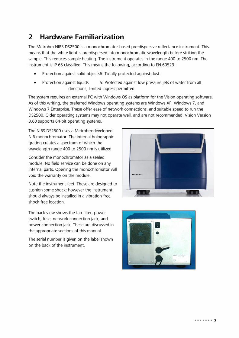
2 Hardware Familiarization The Metrohm NIRS DS2500 is a monochromator based pre-dispersive reflectance instrument. This means that the white light is pre-dispersed into monochromatic wavelength before striking the sample. This reduces sample heating. The instrument operates in the range 400 to 2500 nm. The instrument is IP 65 classified. This means the following, according to EN 60529:
• Protection against solid objects 6: Totally protected against dust.
• Protection against liquids 5: Protected against low pressure jets of water from all directions, limited ingress permitted.
The system requires an external PC with Windows OS as platform for the Vision operating software. As of this writing, the preferred Windows operating systems are Windows XP, Windows 7, and Windows 7 Enterprise. These offer ease of network connections, and suitable speed to run the DS2500. Older operating systems may not operate well, and are not recommended. Vision Version 3.60 supports 64-bit operating systems.
The NIRS DS2500 uses a Metrohm-developed NIR monochromator. The internal holographic grating creates a spectrum of which the wavelength range 400 to 2500 nm is utilized.
Consider the monochromator as a sealed module. No field service can be done on any internal parts. Opening the monochromator will void the warranty on the module.
Note the instrument feet. These are designed to cushion some shock; however the instrument should always be installed in a vibration-free, shock-free location.
The back view shows the fan filter, power switch, fuse, network connection jack, and power connection jack. These are discussed in the appropriate sections of this manual.
The serial number is given on the label shown on the back of the instrument.
8 ▪▪▪▪▪▪▪
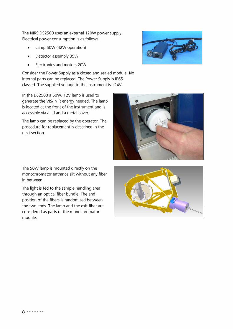
The NIRS DS2500 uses an external 120W power supply. Electrical power consumption is as follows:
• Lamp 50W (42W operation)
• Detector assembly 35W
• Electronics and motors 20W
Consider the Power Supply as a closed and sealed module. No internal parts can be replaced. The Power Supply is IP65 classed. The supplied voltage to the instrument is +24V.
In the DS2500 a 50W, 12V lamp is used to generate the VIS/ NIR energy needed. The lamp is located at the front of the instrument and is accessible via a lid and a metal cover.
The lamp can be replaced by the operator. The procedure for replacement is described in the next section.
The 50W lamp is mounted directly on the monochromator entrance slit without any fiber in between.
The light is fed to the sample handling area through an optical fiber bundle. The end position of the fibers is randomized between the two ends. The lamp and the exit fiber are considered as parts of the monochromator module.

▪▪▪▪▪▪▪ 9
Light is received by an array of detectors, similar to that shown. The light from the monochromator is fed upward through the light tube at the center.
The light impinges on either the instrument reference or the sample, and is reflected back to the detectors. There are four lead sulfide (PbS) and four Silicon (Si) detectors, in an alternating array. They are mounted at a roughly 45-degree angle to the sample, to minimize specular reflection.
The Silicon detectors pick up energy in the 400-1100 nm range. The Lead Sulfide detectors pick up energy in the 1100-2500 nm range.
The reference paddle is situated just below the instrument glass and can be put in three different positions: Sample, reference and wavelength standard. This is controlled by Vision software, based upon the commands sent to the instrument.
• Reference position is shown. The reference paddle covers the sample port.
• Sample position is an open setting, allowing measurement of the sample.
The reference position consists of a fluorilon reflection standard. A window protects the fluorilon standard from the environment and temperature variations.
The wavelength position consists of a wavelength standard (SRM1920A with talc). This is also protected by a window.
The reference paddle is driven by a DC motor and a gear box. It also includes an encoder. The assembly self-finds its home position, so it always repeats its position in front of the light beam.

10 ▪▪▪▪▪▪▪
This shows the reference paddle open (in the sample position) so that the sample can be illuminated, and the light reflected to the detectors can be measured.
The sample cup holder is shown. This must be in position for Vision to allow a sample scan to be taken.
Sample cup adapters contain an RFID (Radio Frequency Identification) device, which tells the instrument what type of sample is in use.
For standards, the cup has a chip. When using the instrument with poly bags or other sample types, no RFID is required.
The sample cup adapter can only be mounted in one orientation – there is a pin which mates to an indentation on the sample rotation assembly, at the very front, to position the adapter correctly.
It is important to keep the sampling window clean at all times, to avoid changes is sample spectra.
The sample cup adapter must be mounted on the DS2500 for the instrument to operate. If no sample cup adapter is present, this message will be displayed.
If this occurs, insert the sample cup adapter and click on “OK” to proceed.

▪▪▪▪▪▪▪ 11
In order not to overheat the lamp, the lamp area is equipped with liquid cooling and a temperature sensor. This assures consistent instrument internal temperature. A fan takes ambient air, passes it through a filter and over the cooling radiator.
If the temperature exceeds 70 °C the lamp will automatically turn off.
A liquid of glycol and water circulates through the system to cool the lamp house. Mix 1:1 glycol (Texaco Havoline XLC PG) with water. If the system has to be refilled the glycol must be found locally. Metrohm will not supply the glycol. The main purpose of using glycol is to avoid corrosion and also to avoid freezing during transportation and storage.
The fan filter is shown. It may be removed for cleaning. It is important to keep the fan filter clean, to allow proper cooling of the instrument.

12 ▪▪▪▪▪▪▪
3 Specifications DS2500 instrument specifications are broken up into categories as follows:
3.1 Safety Certifications: The DS2500 Analyzer is designed and built for safe operation. The instrument is CE labeled and complies with the following safety and quality directives:
• EMC Directive (2004/108/EC)
• Low Voltage Directive (LVD) (2006/95/EC)
• RoHS Directive (2002/95/EC) (Restriction of Hazardous Substances)
• Packaging and packing and waste Directive (94/62/EC)
• WEEE Directive (2002/96/EC) (Waste Electrical and Electronic Equipment)
• REACH Directive (1907/2006/EC) (Registration, Evaluation, Authorization and Restriction of Chemicals)
• Developed and produced according to FOSS ISO approval, ISO 9001
3.2 Installation Parameters The DS2500 Analyzer installation parameters are as shown. Note that the dimensions are in “hard Metric”. The inch conversions are very close, but will be less exact.
Parameter Specification
Width, side to side: 14.8” (375 mm)
Depth, front to back: 19.3” (490 mm)
Height of instrument: 11.8” (300 mm) NOTE: Leave at least 21” (534 mm) height for lid opening
Weight: 59.5 pounds (27kg)
Additional Space Requirements:
Be sure to leave room on all sides for the following:
• Electrical connection
• Ethernet cable connection
• Fan filter access and air flow
• Space in front for sample handling
We suggest a minimum of 4 inches (about 100mm) free space on all sides, including front and back, of the instrument.
Ambient Temperature 41 to 104° F (5 to 40° C) Please note that temperature of samples may affect prediction results.

▪▪▪▪▪▪▪ 13
Ambient Humidity: Less than 93% Relative Humidity, non-condensing
Storage Temperature: -4 degrees F (-20C) to 158 degrees F (70C)
Operating Environment: Stationary when in use, no detectable vibration
EMC Environment: Laboratory use, no abnormal EMC present
3.3 Electrical Specification
Item Specification
AC Mains Electrical Supply: 100-240 VAC, 50-60 Hz, 1.85 A, 120 W AC Mains supply fluctuations not exceeding +/- 10% of rated supply voltage
Network Connections Local Area Network (LAN) – Ethernet, RJ-45 connection
Computer Requirements See Vision computer requirements, or contact your local support office for full information.
3.4 Operating Specifications
Item Specification
Measurement Mode: Reflectance
Wavelength Range: 400-2500 nanometers
Detectors: Silicon (400-1100 nm) and Lead Sulfide (1100-2500 nm)
Optical Bandwidth: 8.75 ±0.1 nm
Spectral resolution: 0.5 nm
Number of data points: 4200
Absorbance Range: Up to 2 AU
Analysis Time: < 1 minute (typical)
Wavelength Accuracy: +/- 0.05 nm (Using Instrument Calibration in Vision)
3.5 Mandatory Safety Notice • Installation of the DS2500 must comply with all applicable local codes.
• Company safety policies must be followed when handling sample materials.
• Proper safety equipment should be worn when handing materials which require protection.
• Any and all site rules are to be followed at all times.

14 ▪▪▪▪▪▪▪
4 Mounting Dimensions The DS2500 Analyzer dimensions are as shown. Note that the dimensions are in “hard Metric”. The inch conversions are very close, but will be less exact.
DS2500 Dimensions and Weight
Width, side to side: 14.8” (375 mm)
Depth, front to back: 19.3” (490 mm)
Height of instrument: 11.8” (300 mm) NOTE: Leave at least 21” (534 mm) height for lid opening
Weight: 59.5 pounds (27kg)
Additional Space Requirements:
Be sure to leave room on all sides for the following:
• Electrical connection
• Ethernet cable connection
• Fan filter access and air flow
• Space in front for sample handling
We suggest a minimum of 4 inches (about 100mm) free space on all sides, including front and back, of the instrument.

▪▪▪▪▪▪▪ 15
5 Electrical Connection Connection of the DS2500 Analyzer is simplified by use of standardized cables which attach to the back of the instrument. The analyzer is shipped with an AC Power Supply with a standard AC molded plug entrance meeting DIN EN 60320-1 specifications. This allows use in each country any custom AC wiring or use of adapter plugs.
Warning: Follow all local safety procedures and codes during installation of the NIR DS2500 Analyzer.
Before starting, verify that the power switch is in the “OFF” position. If it is not, please turn it to off (“O”) as shown.
This photo shows both cable sets. This particular instrument shows a molded plug set as used in North America, at the right side. For other areas, use the correct molded cable to meet local codes.
For communication, an RJ-45 jack is provided. A sealed cable is supplied, which mates to the jack, and provides a connection to the computer or network connection.
The back of the instrument is shown. The fan filter housing is the square assembly on the left side in the photo. Just above and to the right is the AC power switch. The fuse is immediately below the power switch.
Below this, near the bottom, are the AC Mains connection and the RJ-45 cable connection. These are each covered with a protective cap, to prevent entry of contaminants during shipment or storage. Each cap unscrews, and is retained by a flexible attaching cable to prevent loss.

16 ▪▪▪▪▪▪▪
Gently unscrew each molded cover by turning counter-clockwise. Push the cover out of the way as shown.
The upper opening is for AC mains connection, using the cable at the top.
The RJ-45 opening is for the network cable. The locking pin is in the up position then installing the cable.
Each cable has a threaded boot which provides a good splash-proof seal when tightened properly.
With the locking pin up, insert the communications cable into the connector and seat it gently. Next, tighten the rotating ferrule until it is snug, but not so tight than it cannot later be loosened by hand.
Install the AC power cord, taking care that the pins are aligned properly before insertion. The pins can only go in one orientation, and will not allow the plug to be inserted if they are wrong.
Next, tighten the rotating ferrule until it is snug, as above.

▪▪▪▪▪▪▪ 17
Turn the instrument to the ON position as shown. The “I” is pushed inward to turn the instrument on, as with all other equipment following international codes for power switches.
Allow the instrument to warm up and stabilize for approximately one hour to assure consistent operation.
Electrical specifications are as follows:
Electrical Supply 100-240 VAC, 50-60 Hz, 1.8 A, 120 W
Protection IP69k according to IEC 60529 and DIN 40050 part 9, NT ELEC 023

18 ▪▪▪▪▪▪▪
6 Ethernet Connection The DS2500 Analyzer is shipped with a two-meter length of Ethernet communication cable, wired into the instrument and tie-wrapped in place. Do not remove the tie wraps or attempt to change the cable. The cable should last the life of the DS2500 Instrument.
The cable type is as follows:
• Category 5e, SF/UTP Patch 4P
• IEC 61156-6 LSHT
• (or equivalent)
The exposed end of the Ethernet cable has an RJ-45 plug like that shown in the photo at right.
The exposed end should be connected to the LAN, and the connection should be shielded from wash-down, dirt, vibration, and tampering.
It is advisable to place the DS2500 Analyzer within the same “network neighborhood” as the computer on which Vision is installed. They should be under the same network “subnet mask”.
Because network setups vary dramatically from company to company, Metrohm cannot provide troubleshooting for a specific network. That is the responsibility of company IT and Network Support personnel.
As a rule, if the DS2500 Analyzer can communicate locally (whether through a local router or other means) then it is capable of network communication through a Local Area Network (LAN). Wide Area Networks (WAN) may pose problems due to different subnet masks, security issues, or firewalls between different parts of the network. Please consult your local support personnel for help with these issues.
It is very important to know if the connection cable is a “patch” or “crossover” type of cable. While the cables are usually marked in some manner, one way to verify is to view the ends of the cable together.
Patch cable:
When held with both ends as shown, conductors up, both ends of a patch cable will appear identical.
The “solid” orange, blue, green and brown will be in the same positions on each jack.
The striped wires may appear white, as in this photo, or the stripes may appear more clearly.

▪▪▪▪▪▪▪ 19
Crossover Cable:
When held with both ends as shown, conductors up, the wire patterns are different.
Note the left plug – the order of solid wires is orange, blue, green, and brown.
On the right plug, the order of solid wires is green, brown, orange, and blue.
On a crossover cable, the pairs are designed to “cross over” the signal when devices are hooked directly to each other, instead of through a network switch.
Devices area available with can plug into a cable and change the cable type from crossover to patch, or the other direction. In the latest networks, the type of cable may not matter, as the system sense the signal and corrects the pin signals as required. This is called “automatic MDI/MDI-X configuration”.
Because of the many variations in network design, capability, permissions, and administration, a full discussion is not possible in this manual. The field is very dynamic, and we recommend consultation with network personnel on these issues if problems arise.

20 ▪▪▪▪▪▪▪
7 Connection to Vision Software DS2500 is designed to operate with Vision software. Vision requires a User ID and password for entry as a security measure. Each user must operate within a “Project” inside Vision. The procedure for creating a Project will be shown. Inside the Project, Vision uses a Data Collection Method (DCM) to communicate with the DS2500 Analyzer.
Please follow this procedure to connect:
1. Click on the Start icon, then click on Vision in the menu as shown.
Alternatively, if a Vision icon appears on the desktop, double-click it to open Vision.
2. The Vision log-in box is shown. Type in the default User ID “NIRS” and then the default password, “NIRS”.
Click “OK”. Vision will open.
3. Vision prompts the user to create a new Project. Enter the name of the Project, using a logical name such as that shown, or a name related to the product being analyzed.
The name can be up to 16 characters, with no spaces. It may not contain characters like “/”, “+”, “*”, or other such characters. The name will be shown in lower-case.
Location may be left empty, and Vision will place the Project database in the default Vision directory.
Click “OK”.
▪▪▪▪▪▪▪ 21
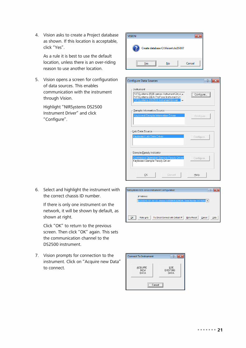
4. Vision asks to create a Project database as shown. If this location is acceptable, click “Yes”.
As a rule it is best to use the default location, unless there is an over-riding reason to use another location.
5. Vision opens a screen for configuration of data sources. This enables communication with the instrument through Vision.
Highlight “NIRSystems DS2500 Instrument Driver” and click “Configure”.
6. Select and highlight the instrument with the correct chassis ID number.
If there is only one instrument on the network, it will be shown by default, as shown at right.
Click “OK” to return to the previous screen. Then click “OK” again. This sets the communication channel to the DS2500 instrument.
7. Vision prompts for connection to the instrument. Click on “Acquire new Data” to connect.

22 ▪▪▪▪▪▪▪
8. The DS2500 instrument runs an automatic self-checking routine upon connection. When this screen is shown, wait a minute or two for the test to complete. No operator input is required.
9. When finished, the screen indicates successful testing. Click on “OK” to proceed.
10. Vision requests a valid Data Collection Method (DCM) in this screen. Since no DCM has been created yet, click on “New”.

▪▪▪▪▪▪▪ 23
11. The DS2500 Analyzer sends its configuration to the Data Collection Method – this is a Reflectance system, as shown in the Sampling system “Module” box.
The wavelength range is 400-2500 nanometers. Reference Standardization is a default for this model, and the box is checked.
The “Method” name is empty when the DCM is displayed. Enter a name for the method. The name used here is “DS2500 Refl”. Spaces are allowed in the DCM name.
Click “OK” when finished.
12. Vision displays the selection box for the DCM. Click on the method just created, then click on “OK”.
You may hear some clicking noises from the DS2500 instrument as it executes internal checks. These noises are normal.
13. Vision checks to verify that the instrument is stable. If the DS2500 was just turned on, this may take some time, depending on ambient temperature.
Once the instrument is stabilized, this box is removed from the screen.

24 ▪▪▪▪▪▪▪
14. Vision displays the instrument configuration, so the user may confirm that this is the correct instrument.
This information is used to create a path in the Diagnostic Database.
Click on “OK”.
15. A series of self-tests is performed on the DS2500. This result will be shown upon completion.
Click on “OK” to close the box.
16. When the system is ready to run, the Diagnostics menu will become active.
17. Please proceed to the section on DS2500 Diagnostics.
▪▪▪▪▪▪▪ 25
8 DS2500 Diagnostics Diagnostics are provided to assure ongoing performance of the DS2500 instrument. Upon each connection to the instrument, Self-Test is performed automatically. The instrument monitors itself for basic diagnostics, and will alert the operator in the event of malfunction.
It is wise to institute ongoing testing to monitor instrument performance and operation. The frequency for this testing depends upon application and usage, and should be set by the System Manager and other personnel who are preparing the system for use. This team of people will have the best information on frequency of use, and the need for ongoing testing.
This manual gives specific directions for each configuration. Tests are described below.
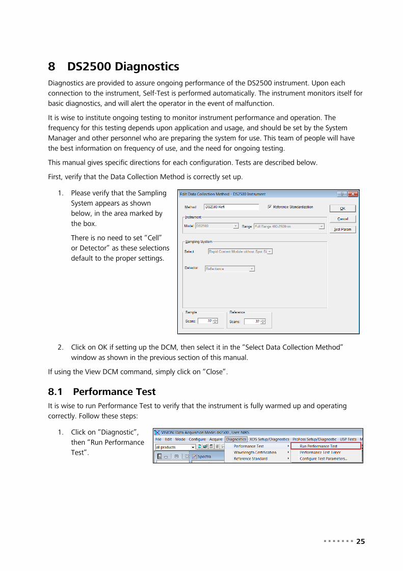
First, verify that the Data Collection Method is correctly set up.
1. Please verify that the Sampling System appears as shown below, in the area marked by the box.
There is no need to set “Cell” or Detector” as these selections default to the proper settings.
2. Click on OK if setting up the DCM, then select it in the “Select Data Collection Method” window as shown in the previous section of this manual.
If using the View DCM command, simply click on “Close”.
8.1 Performance Test It is wise to run Performance Test to verify that the instrument is fully warmed up and operating correctly. Follow these steps:
1. Click on “Diagnostic”, then “Run Performance Test”.

26 ▪▪▪▪▪▪▪
2. If the lid of the DS 2500 is open, this message will be displayed. Gently push the lid down to close it. It will latch when fully closed.
Click “OK” to continue.
NOTE: It is normal to close the DS2500 cover when running tests. Vision may prompt the user to close the cover at certain points during operation.
If the cover is not closed, the test may run normally, as a result of very good light blocking within the instrument. If not, be sure to always close the cover when prompted.
3. Vision displays the Instrument Configuration box upon initial connection. This information is used to set up the Diagnostic Database entries for this instrument.
If correct, click on “OK”.
This box is shown upon each initial connection, and is not shown on subsequent diagnostic tests, as long as the instrument has remained connected to Vision.
4. When running Performance Test on the DS2500, the instrument reference is placed in the correct position. The instrument firmware moves the reference into the correct position.
NOTE: It is normal to close the DS2500 cover when running tests. Vision may prompt the user to close the cover at certain points during operation.
If the cover is not closed, the test may run normally, as a result of very good light blocking within the instrument. If not, be sure to always close the cover when prompted.

▪▪▪▪▪▪▪ 27
5. Vision initiates the test. A split-screen display is shown as the test proceeds.
Scroll the mouse over the center bar, click, and drag left to open the right side of the window larger.
6. This affords the user a better view of the spectra, as well as results as they scroll upward on the lower part of the screen.
This test normally takes about 20 minutes for ten sets of scans.
7. When the test is finished, the split-screen display will appear as shown.
Double-click on the tabs at the bottom of the screen to see the tabulated results.

28 ▪▪▪▪▪▪▪
8. The tabulated results show these items:
• Scan: 10 is the default value.
• EOC: Errors on communication – this will be “0” nearly all the time.
• P-P: Peak to Peak noise
• Minimum: Magnitude of lowest-going noise peak
• Wavelength: Location of negative peak
• Maximum: Magnitude of highest-going noise peak
• Wavelength: Location of positive peak
• Bias: Baseline offset of noise scans
• RMS: Root-mean-square value of P-P
• Gain: Not used on this instrument

▪▪▪▪▪▪▪ 29
9. The “OpQual” tab gives acceptance specifications, along with actual results and a “Yes/No” indicator to test status.
The first page gives information on Peak-to-Peak noise, RMS noise, and Bias.
10. The “OpQual2” page gives information on wavelength performance.
7. If a printed copy is needed, click on “Print Report”.
A copy is automatically saved to the Vision Diagnostic Database. Click on “Close Report” when finished.
8.2 Instrument Calibration Instrument Calibration is a method to set the photometric and wavelength scales of the instrument to known, repeatable values. For DS2500, this function combines the adjustments of two separate XDS functions, Reference Standardization and Instrument Calibration. By so doing, tests are streamlined, and provide optimal results with less effort.

30 ▪▪▪▪▪▪▪
Ideally, the instrument reference scale should be set so that 100% reflectance is equivalent to zero (0) Absorbance. This facilitates transfer of models from one instrument to another of the same optical sampling geometry.
In practice, it is challenging to set the scale exactly, due to issues of cleanliness, temperature, and atmospheric influences. Fortunately, NIR instruments normally use mathematical and chemometric modeling methods that compensate for minor photometric scale differences between instruments.
1. Click on “Diagnostics”, then “Instrument Calibration”.
This test is required to set the photometric scale to a known absorbance value, and the wavelength scale to known peak positions.
2. Vision shows this selection box, marked “Select Standard File”. Insert the CD (or other media) that comes with the standard set into the computer drive. (In this case, D: is used.)
From the CD or DVD drive, highlight the RSS1xxxx file, then click “Open”.
3. Vision prompts the user to place the WSR1xxxx wavelength standard from the standard set into the sample holder.
Be sure the serial number of the standard is the same as that shown on screen. Close the lid and click on “OK”.

▪▪▪▪▪▪▪ 31
4. Click “OK” when the standard is in position.
It is wise to always orient the standard in the same rotational position. In this case, we suggest the label be parallel with the flat spot on the sample chamber wall.
Click on “OK” to proceed.
5. Vision acquires an instrument reference. No action is required.
6. Vision prompts for positioning of the R80 reference, from the same standard set.
7. Place the R80 in position as shown.
Close the lid and click on “OK”.

32 ▪▪▪▪▪▪▪
8. Vision acquires another instrument reference scan. No action is required.
9. Vision reports that Instrument Calibration has passed successfully.
Click on “Print” if a copy is desired. Otherwise, click on “OK” to close the test.
10. The printed report appears as shown.
8.3 Wavelength Certification This test verifies that the wavelength scale of the DS2500 meets parameters specified by the U.S. National Institute of Standards and Technology (N.I.S.T.) for NIR wavelength response using rare-earth standards.
1. 1. Click on “DS2500 Setup/Diagnostic”, then “Run Wavelength Certification”.
2. The default number of scans is 10. The default selection is “Wavelength Standard (SRM-1920 with talc)”.
Click “OK”.

▪▪▪▪▪▪▪ 33
3. The Standards set contains a mini-CD with the standards file on it. Click on this file, then click “Open”.
Vision initiates the test.
4. Vision begins taking an instrument reference spectrum.
5. Vision requests that the user place the wavelength standard onto the sample window.
Do not click “OK” yet.
6. Verify that the serial number of the standard is the same as that shown in the Vision prompt box. Close the lid as directed.
Click “OK” when ready. Vision will start the test.
7. This test runs in about 8-9 minutes. Split-screen results appear as shown.
Double-click on the lower right quadrant to see full tabulated results.

34 ▪▪▪▪▪▪▪
8. There are four wavelength peaks used, which serve to characterize the full wavelength scale of the instrument.
N.I.S.T. uncertainty is applied for rare-earth-type wavelength standards, shown as a tolerance of +/-1.0 nm.
The Pass result is shown on this report for each wavelength peak tested.

▪▪▪▪▪▪▪ 35
9. The tab for Instrument Calibration Verification checks that the fine wavelength tuning performed during Instrument Calibration is still stable.
Instrument Calibration set the wavelength scale, using well-established peaks in the rare-earth materials. This test verifies that those peaks are still within +/- 0.05 nm of the target positions. This assists in model transfer between like instruments.
10. If a printed copy is needed, click on “Print Report”.
A copy is automatically saved to the Vision Diagnostic Database. Click on “Close Report” when finished.
NOTE: We advise removing the standards from the sample window when not in use. The NIR light beam can warm the standards somewhat, which will change their wavelength response. Please place the standards on the window only for current testing, and remove them promptly when finished.
8.4 IPV Setup This setup function stores spectra of photometric standards to document the photometric response of the DS2500 instrument upon initial setup and operation. This stores a file in the C:\Vision directory of that response. The stored file is later used to test against, to verify that the photometric scale of the instrument has not changed beyond allowable limits.
This file may need to be re-run when one of the following conditions has occurred:
• A different set of standards is used with the instrument (standard sets are not interchangeable)

36 ▪▪▪▪▪▪▪
• The standards themselves may have changed in some way, from spills, dropping, scratching, or other damage
• The instrument has undergone service work that could have changed the photometric response in some way.
Follow this procedure to set up the IPV Setup file:
1. Click on “Diagnostics”, then “IPV Setup”.
2. Select the standard file from the mini-CD. Highlight it, then click “Open”.
3. For Number of Replicates, enter “1”. As long as the standards are repeatably positioned, only one replicate should be required.
Click “OK”.
4. Close the lid as prompted. Click on “OK”.

▪▪▪▪▪▪▪ 37
5. Insert the R99 standard as directed. The serial number of the standard should match the serial number shown in this message.
6. Place the R99 standard with the label parallel to the front wall of the instrument, for best repeatability.
After positioning, click on “OK”.
7. After the R99 standard has been scanned, Vision will plot it at the upper right, and will request the operator to position the R40 standard.
8. Remove the R99 standard and place it back into the standards box. Position the R40 standard. Close the lid and click “OK”.
9. Repeat as directed for the R20, R10, and R02 standards.

38 ▪▪▪▪▪▪▪
10. When finished, click on “OK” The standard file will be stored in the C:\Vision directory. It will be named RSSvxxxx, where the last four digits are the same serial number as the standard set.
Click on “Close Report”.
8.5 Photometric Test This test compares currently-acquired spectra to previously-stored spectra of photometric standards to verify that the response of the instrument has not changed appreciably.
When Photometric Test is run, it requires that the same set of standards is used as was originally used, when the IPV Setup was performed. The reason is that standards are not photometrically identical – they are very similar in response, but one set may be different from another, enough to cause a failure during Photometric Test. Therefore, always use the same set for this test.
Follow this procedure to run Photometric Test:
1. Click on “Diagnostics”, then “Photometric Test”.
2. A note is displayed, explaining the location of the RSSvxxxx.da file. It is located in the C:\Vision directory.
Click on “OK” to continue.
3. Select the standard file from C:\Vision as shown. Highlight the file, then click “Open”
Note that the serial number will be the same as that used for IPV Setup.
▪▪▪▪▪▪▪ 39
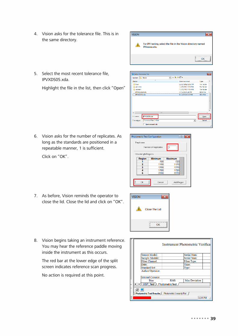
4. Vision asks for the tolerance file. This is in the same directory.
5. Select the most recent tolerance file, IPVXDS05.xda.
Highlight the file in the list, then click “Open”
6. Vision asks for the number of replicates. As long as the standards are positioned in a repeatable manner, 1 is sufficient.
Click on “OK”.
7. As before, Vision reminds the operator to close the lid. Close the lid and click on “OK”.
8. Vision begins taking an instrument reference. You may hear the reference paddle moving inside the instrument as this occurs.
The red bar at the lower edge of the split screen indicates reference scan progress.
No action is required at this point.

40 ▪▪▪▪▪▪▪
9. When the reference scan is complete, Vision prompts the operator to place the R99 standard in position. As before, place the standard in a repeatable manner into the sample holder.
10. Place the R99 into the sample cup adapter as shown, with the edge of the label parallel to the flat wall of the sample chamber. Close the lid.
Click on “OK” to initiate the scan.
11. The results of the R99 scan are shown, along with tabulated results for the applicable wavelength regions.
12. Vision requests the R40 standard. Remove the R99, and insert it into the wooden box for safekeeping.
Place the R40 standard in the holder, then click on “OK”.
13. Continue in this manner as prompted by Vision. Insert standards R20, R10, and R02 as prompted.

▪▪▪▪▪▪▪ 41
14. Vision reports the results of Photometric Test in this format.
Photometric response is averaged across five regions of the spectrum, and compared to the stored spectra created during IPV Setup. The differences are computed. As long as the Average Bias Log(1/R) is within the assigned tolerances, the instrument is presumed to be operating in a stable manner on the photometric scale. This results in “Pass” in the right-hand column.
15. Vision indicates the test has passed. To print the report, clock “Print Report”.
To close the test, click “Close Report”.

42 ▪▪▪▪▪▪▪
9 Sampling Once Vision Diagnostics have been performed, the user may take reference and sample spectra. In Data Acquisition, these actions are performed.
First, click on the Reference icon, which is a white cuvette.
When the Reference spectrum is finished, continue below.
Insert a sample into the holder. Close the lid.
Next, click on the Sample icon, which is a green cuvette.
When the Sample spectrum is shown on screen, it may be saved.
To save the sample spectrum, click on the blue diskette icon. Vision will ask for product and sample names, and other information. Please see the Vision manual for full information on saving spectra.
If the sample cup adapter is not in place, Vision will show this error message. Insert the adapter, click on “OK” and proceed.
The sample cup adapter should be placed so the locating pin is properly inserted into the opening in the rotating sample assembly. If this message appears, it indicates that the sample cup adapter may not be in the correct position.
Check the adapter, correct the position, and click on “OK”.
Further information on sampling, spectral manipulation, and calibration can be found in the Vision software manual.

▪▪▪▪▪▪▪ 43
10 Maintenance Maintenance items are explained as follows:
10.1 Instrument Cleanliness Instrument cleanliness is important, as dust and dirt inside the sampling area can have an adverse effect upon analytical results.
Periodically use a soft cloth, moistened slightly, to wipe any fingerprints or dust off the instrument. If needed, carefully wipe out the sampling area too.
The sample window may be cleaned with a lint-free wipe, such as a Kim-Wipe, then brushed with the sample brush to remove any slight residue.
10.2 Lamp Replacement The lamp may be replaced by the user when the existing lamp has burned out or become otherwise unsuitable for use in analysis. The instrument should be cleaned before replacement of the lamp to prevent dust from damaging the reflector. (Cleaning can be done with a slightly moistened, soft cloth.) Lamp replacement should be performed in a clean environment.
Caution
Do not touch the lamp glass or reflector. The lamp can be damaged by fingerprints and oily residues. Do not let any rough surface come into contact with the lamp glass. A microscopic scratch in the clear glass envelope could cause a lamp explosion later.
1. Turn the power switch to “O”, which is the off position.
2. We recommend unplugging the power supply from AC power. This provides an additional measure of safety.
We also recommend waiting at least 10-15 minutes after power-down before accessing the lamp area. This gives the lamp time to cool, and prevents injury.

44 ▪▪▪▪▪▪▪
3. Open the lower door on the front of the DS2500 as shown.
4. Using the 4mm metric Allen wrench stored in the door, loosen the four screws which hold the lamp door in place.
5. Locate your new lamp. It will be packaged in a Metrohm box.
Remove from box, without touching either the reflector or the clear glass bulb at the center of the reflector.
6. Push the white lamp holder INWARD about 2mm, then rotate the lamp in a counter-clockwise direction, about one-eighth of a turn, and pull outward as shown.
Stated more simply:
• Push inward 2mm.
• Rotate so the top turns to the left, 1/8 turn.
The wires will remain attached. Remove gently.

▪▪▪▪▪▪▪ 45
7. Set the lamp on the instrument door as shown.
Study how the lamp is placed in the lamp holder:
• Note the spring which positions the lamp.
• Note how the wires feed through the while lamp holder.
8. Using a small, flat-bladed screwdriver, loosen the screws which hold the old lamp wires to the white holder. Loosen one turn, which will be enough to remove the wire.
DO NOT loosen the black wires – these are not to be loosened or adjusted under any circumstances.
9. Gently pull the white wires out of the holes where they were secured by the screws.

46 ▪▪▪▪▪▪▪
10. Straighten the white wires upward. Gently lift the lamp holder off the lamp. Do not let the lamp fall – hold it by the rectangular base if needed.
(The lamp was allowed to cool down, and should be safe to touch.)
11. This shows the old lamp removed from the white lamp holder.
Handle gently. Though the lamp is bad, it is still fragile.
Set this lamp aside – do not get confused which is the new, and which is the old lamp. Some technicians twist the wires to indicate that the lamp is used.
12. With the new lamp, straighten the wires so they will fit through the lamp holder.
This view shows the lamp holder – note the rectangular opening, which fits the rectangular base of the lamp.
Prepare to insert the new lamp into the holder.

▪▪▪▪▪▪▪ 47
13. With the wires straight, lower the lamp holder down onto the base of the lamp as shown.
It is fine to let the holder spring rest on the lamp reflector. It is also acceptable to use the ridge on the lamp door as a means of restraining the lamp from moving too far.
14. Insert one wire into the terminal connection in the lamp holder.
This may be easier with needle-nose pliers, as shown. Do not puncture or damage the Teflon wire insulation.
Be sure the wire end is fully inside the screw terminal in the lamp holder.
15. With the wire end fully inside the terminal, tighten the screw to secure the wire end.
48 ▪▪▪▪▪▪▪
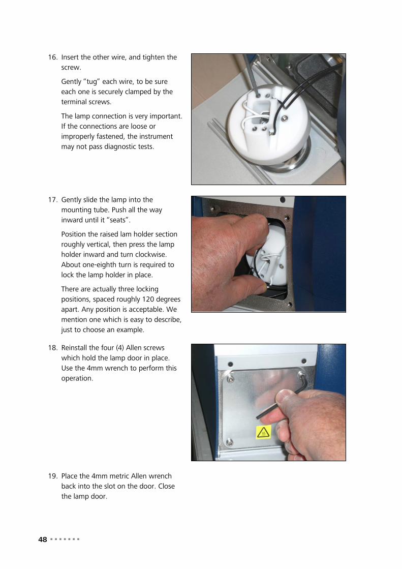
16. Insert the other wire, and tighten the screw.
Gently “tug” each wire, to be sure each one is securely clamped by the terminal screws.
The lamp connection is very important. If the connections are loose or improperly fastened, the instrument may not pass diagnostic tests.
17. Gently slide the lamp into the mounting tube. Push all the way inward until it “seats”.
Position the raised lam holder section roughly vertical, then press the lamp holder inward and turn clockwise. About one-eighth turn is required to lock the lamp holder in place.
There are actually three locking positions, spaced roughly 120 degrees apart. Any position is acceptable. We mention one which is easy to describe, just to choose an example.
18. Reinstall the four (4) Allen screws which hold the lamp door in place. Use the 4mm wrench to perform this operation.
19. Place the 4mm metric Allen wrench back into the slot on the door. Close the lamp door.

▪▪▪▪▪▪▪ 49
20. Plug power cord back in. Turn the instrument “ON” and let it warm for one hour.
21. When the instrument is fully warmed up, perform these tests:
Performance Test
Instrument Calibration
Once these tests have both passed, the instrument is ready to run.
10.3 Fan Filter Replacement The fan filter may become dusty or clogged after operating for some time. It is wise to check it at least monthly, or more often in dusty environments. A clean filter is important in maintaining the internal instrument temperature. When the filter needs cleaning or replacement, follow the instructions given below:
1. The fan filter is located on the back of the DS2500 as shown.

50 ▪▪▪▪▪▪▪
2. Using a small, flat-bladed screwdriver, gently pry the cover off the fan housing.
3. With the cover off, remove the filter material.
Inspect for rips and general condition. If the condition is good, and no rips or tears are present, it may be cleaned.
This may be done by blowing with clean, dry instrument air, or by gently rinsing in clean, clear water. If water is used, be sure the dry the filter before replacing it into the filter frame.
If a replacement filter is needed, please contact your local Metrohm distributor for help.
4. When finished, snap the filter frame, with clean filter material in place, back onto the instrument.
10.4 Fuse Replacement The fuse is located on the back of the instrument, directly below the power switch.
1. Turn instrument power to OFF (O) on the power switch. This switch is highlighted in the photo with a red box.
We recommend the instrument be unplugged after power-down, to avoid accidental power-up.

▪▪▪▪▪▪▪ 51
2. The fuse is highlighted with a red circle in this photo.
3. It may be removed either by use of a small (#1) flat-blade screwdriver, or by unscrewing by hand.
4. After unscrewing the fuse holder, the fuse may be removed from the holder. Discard any blown or damaged fuses.
Place a new fuse into the holder. The fuse type is:
• T5AL250VP
This is a 20mm, 250V, 5A Time delay fuse. Use only the exact equivalent.

52 ▪▪▪▪▪▪▪
5. With the new fuse in the holder, hand-thread the use holder into the instrument. Tighten gently.
We do not advise use of a screwdriver to tighten the fuse. Hand-tight is sufficient.
This photo illustrates why we recommend the instrument be unplugged when replacing the fuse – this technician’s knuckles could inadvertently turn the power switch ON when replacing the fuse.
6. Plug in the instrument, and turn power on. The instrument should power up. The indicator light on the front panel should light up. The instrument will make a few noises as it does an internal test.
Allow the instrument to reach operating temperature before resuming analysis.
7. Assuming no optical changes or failures caused the fuse to blow, there should not be a need to run diagnostic tests. It is wise, however, to determine what caused the fuse to blow. If the condition can be corrected, this should be done before proceeding to use the instrument.