nilan cts602 light, modbus specification
TRANSCRIPT

Protocol description
Nilan CTS602Light Modbus version 20
517210
Created 12.09.2008
Revision 19.03.2019

517210
Nilan CTS602 Light, Modbus specification
Version 20
19.03.2019 FGJ 2 af 18 CTS602Light_Modbus.doc
Table of Contents
1. Revision history ....................................................................................................................... 2 2. Connection ............................................................................................................................... 2 3. Setup ......................................................................................................................................... 4 4. Supported functions.................................................................................................................. 4 5. Register layout ......................................................................................................................... 5
5.1 Register groups .............................................................................................................. 5 5.2 Input registers ................................................................................................................. 6
5.2.1 Diplay ............................................................................................................. 9 5.3 Holding registers .......................................................................................................... 11
5.3.1 Display .......................................................................................................... 15 6. Communication example ........................................................................................................ 18
1. Revision history
Version Software Date Description
20 1.1.19.0 08-03-2019 Breakup from CTS602 1.6.21.0.
This version includes only Modbus registers which are implemented
in CTS602 Light version 1.1.19.0
“Version” refers to the protocol data item named “Bus.Version”.
2. Connection The Modbus is wired to PIN 2,3,6 on connector CN 7 located next to the USB plug on the CTS 602 board.
Pin 1 12 VDC output
Pin 2 COM1 - RS 485 Data+ (A) - Modbus
Pin 3 COM1 - RS 485 Data- (/B) - Modbus
Pin 4 COM2 - RS 485 Data+ (A) - User panel
Pin 5 COM2 - RS 485 Data- (/B) - User panel
Pin 6 Ground
CTS 602 Modbus connector:
Point to point bus wiring:

517210
Nilan CTS602 Light, Modbus specification
Version 20
19.03.2019 FGJ 3 af 18 CTS602Light_Modbus.doc
Modbus
MasterCTS602
Modbus (RTU) via RS485 (2-wire)
120 ohm
Terminat ion
resistor
120 ohm
Termination
resistor
Cable specification:
Tinned twisted-pair, with foil or braided
shield, connected to ground only on the
master side.
Max 200 m cable length.
Characteristic impedance 100 - 130 Ohm.
Shunt capacitance < 100 pF/m.
AWG 24 / 0,25 mm2.
Suggested types: Belden 941/942 or
Multicable LIYCY-P 2*2*0,25 mm2.
Common ground:
All network nodes must share a common
ground connection as the bus signals shall
refer to the same voltage potential.
There is no opto-isolation on the CTS602.
Network termination:
120 Ohm resistors shall be connected
between the two RS485 signal wires at
each end-point of the bus wire.
The resistor value shall match the
characteristic impedance of the cable.
Receiver impedance >= 12 kOhm.
Linear bus wiring:
Modbus
Master
CTS602
CTS602
Modbus (RTU) via RS485 (2-wire)
CTS602
CTS602
120 ohm
Terminat ion
resistor
120 ohm
Terminat ion
resistor
#1
#2
#3
#10
...

517210
Nilan CTS602 Light, Modbus specification
Version 20
19.03.2019 FGJ 4 af 18 CTS602Light_Modbus.doc
3. Setup
Protocol Modbus (RTU mode), see http://www.modbus.org/specs.php
Node address Default 30, Address is selectable between 1 and 247
Device type CTS 602 Light is a Modbus slave
Baud rate 19.200
Databits 8
Stopbits 1
Parity Even
Packet size Max. 255 bytes
Communication speed and parameters cannot be changed, except for the node address.
4. Supported functions Input and holding registers are supported.
Unless otherwise specified, all registers are 16 bit size.
The controller will respond to the below listed Modbus message functions only.
Please note that no other function codes are supported.
Function Name Description
03 Read Holding Registers Read one or more holding registers
04 Read Input Registers Read one or more input registers
16 Preset Multiple Registers Write one or more holding registers
Master Slave
Initiate request
Perform the action.
Initiate the response
Receive the
response
Function code Data Request
Function code Data Response

517210
Nilan CTS602 Light, Modbus specification
Version 20
19.03.2019 FGJ 5 af 18 CTS602Light_Modbus.doc
5. Register layout Register addresses are given in decimal notation.
Input registers are located in the range 30001..39999.
Holding registers are located in the range 40001..49999.
NOTE:
In the tables below we list the register addresses as used in Modbus messages without the global offset.
That means if you read input regsiter 100 with function code 04, you get the global address 30101.
NOTE:
All input registers can also be read as type holding register with function code 03 by adding the offset value 10000
to the register address. No writes will be accepted in this range.
5.1 Register groups
The protocol data is grouped into the following address ranges with 100 registers in each group. This applies to
both input and holding register types:
Name Address Description VPM VPL VP VGU COMF
Device 000 Protocol and controller setup x x x x x
Discrete I/O 100 Input / output bits (on/off) x x x x x
Analog I/O 200 Input / output words x x x x x
Time 300 Clock and calendar x x x x x
Alarm 400 Alarm and message handling x x x x x
Week program 500 Calendar based programming x x x x x
User functions 600 User input function selection x x x x x
Data log 700 Data, alarm and event logging x x x x x
-- 800 --
-- 900 --
Control 1000 System control and status x x x x x
AirFlow 1100 Ventilation control x x x x x
AirTemp 1200 Room temperature control x x x x
AirBypass 1300 Exchanger bypass control x x
AirHeat 1400 Inlet air heater control x x x
Compressor 1500 Compressor operation control x x x x
Defrost 1600 Defrosting control x x x x x
HotWater 1700 Hot water control x x
CentHeat 1800 Central heating control (EK) x x
AirQual 1900 Air quality control (RH, CO2) x x x x x
User panel 2000 Display and keyboard x x x x x
PreHeat 2100 Intake air preheat / earth tube x x
DPT 2200 Difference pressure transducer x
Display – Input reg. 3000..3199 Input registers for display uses -- -- -- -- --
Display – Holding reg. 4000..4199 Holding registers for display uses -- -- -- -- --

517210
Nilan CTS602 Light, Modbus specification
Version 20
19.03.2019 FGJ 6 af 18 CTS602Light_Modbus.doc
5.2 Input registers
Name Address Scale Unit Description
Bus.Version 000 Protocol version number
App.VersionMajor 001 text Software version - major (2 character ascii text)
App.VersionMinor 002 text Software version - minor (2 character ascii text)
App.VersionRelease 003 text Software version - release (2 character ascii text)
Input.UserFunc 100 User function
Input.AirFilter 101 Air filter alarm
Input.Smoke 103 Smoke alarm
Input.Frost_Overht 105 Heating surface frost / overheat
Input.UserFunc_2 113 User function 2
Input.DamperClosed 114 Air damper closed position switch
Input.DamperOpened 115 Air damper opened position switch
Input.T0_Controller 200 100 °C Controller board temperature
Input.T3_Exhaust 203 100 °C Room exhaust temperature
Input.T4_Outlet 204 100 °C Outlet temperature
Input.T7_Inlet 207 100 °C Inlet temperature (after heater)
Input.T8_Outdoor 208 100 °C Outdoor temperature
Input.T9_Heater 209 100 °C Heating surface temperature
AirQual.RH 221 100 % Humidity sensor value
AirQual.CO2 222 ppm Carbon dioxide sensor value

517210
Nilan CTS602 Light, Modbus specification
Version 20
19.03.2019 FGJ 7 af 18 CTS602Light_Modbus.doc
Name Address Scale Unit Description
Alarm.Status 400 Alarm state bit mask
0x80 : Active alarm(s) are present
0x03 : Number of alarms listed
Alarm.List_1_ID 401 Alarm 1 - Code
0x80 : (reserved future use)
0x7F : Display code 1..99
Alarm.List_1_Date 402 Alarm 1 - Date
Bit word packed in DOS date format
Year 0 = 1980 15 8 7 0
YYYYYYYM MMMDDDDD
Alarm.List_1_Time 403 Alarm 1 - Time
Bit word packed in DOS time format
Seconds are in scale 2 (0..29 = 0..58 seconds) 15 8 7 0
HHHHHMMM MMMSSSSS
Alarm.List_2_ID 404 Alarm 2 - Code
Alarm.List_2_Date 405 Alarm 2 - Date
Alarm.List_2_Time 406 Alarm 2 - Time
Alarm.List_3_ID 407 Alarm 3 - Code
Alarm.List_3_Date 408 Alarm 3 - Date
Alarm.List_3_Time 409 Alarm 3 - Time
Control.RunAct 1000 Actual on/off state
0 : Off
1 : On
Control.ModeAct 1001 Actual operation mode
0 : Off
1 : Heat
2 : Cool
3 : Auto
4 : Service
Control.StateDisplay 1002 Actual control state
0 : Off
1 : Shift
2 : Stop
3 : Start
4 : Standby
5 : Ventilation stop
6 : Ventilation
7 : Heating
8 : Cooling
9 : Hot water
10 : Legionella
11 : Cooling + hot water
12 : Central heating
13 : Defrost
14 : Frost sequre
15 : Service
16 : Alarm
17 : Heating + hot water
Control.SecInState 1003 Sec Actual time in state
AirFlow.VentSet 1100 Step Actual ventilation step set point
0 : Off
1..4 : Step number
AirFlow.InletAct 1101 Step Actual inlet fan speed step
0 : Off
1..4 : Step number
AirFlow.ExhaustAct 1102 Step Actual exhaust fan speed step
0 : Off
1..4 : Step number
AirFlow.SinceFiltDay 1103 Days Days since last air filter change alarm
One day is measured as 24 hours of active running time
AirFlow.ToFiltDay 1104 Days Days to next air filter change alarm
One day is measured as 24 hours of active running time
517210
Nilan CTS602 Light, Modbus specification
Version 20
19.03.2019 FGJ 8 af 18 CTS602Light_Modbus.doc
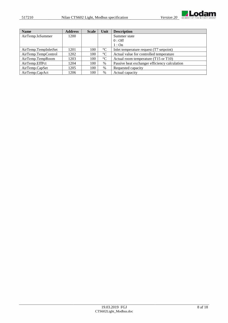
Name Address Scale Unit Description
AirTemp.IsSummer 1200 Summer state
0 : Off
1 : On
AirTemp.TempInletSet 1201 100 °C Inlet temperature request (T7 setpoint)
AirTemp.TempControl 1202 100 °C Actual value for controlled temperature
AirTemp.TempRoom 1203 100 °C Actual room temperature (T15 or T10)
AirTemp.EffPct 1204 100 % Passive heat exchanger efficiency calculation
AirTemp.CapSet 1205 100 % Requested capacity
AirTemp.CapAct 1206 100 % Actual capacity

517210
Nilan CTS602 Light, Modbus specification
Version 20
19.03.2019 FGJ 9 af 18 CTS602Light_Modbus.doc
5.2.1 Diplay
Name Address Scale Unit Description
AirBypass.IsOpen 3000 Bypass damper
0: Closed
1: Open
Output.AirHeatCap 3001 100 % After heating element
0.00 – 100.00%
AirQual.CO2_Enable 3003 CO2 sensor present in the system or not
0: Off
1: On
AirFlow.RoomReduce 3004 Stop at low room temperature
0-4
AirFlow.LastTestDay 3005 Date for last air damper self-test
Runtime hours is counted and formatted to days
0 - 65535
AirFlow.SinceFiltDay 3006 Days since last air filter change
One day is measured as 24 hours of active running time.
0-9999
AirFLow.WinterReduce 3007 Low fan speed at low outdoor temperature
Level 0-4
AirTemp.TempSet 3008 100 °C Actual resulting set-point for room temperature
5.00°C - 50.00°C
AirTemp.TempControl 3009 100 °C Master sensor for the controlled temperature (room / inlet)
-40.00°C – 99.00°C
Alarm.LogEventID 3050 Event log ID (alarm code)
0 – 255
Alarm.LogDate 3051 DATE_DOS Date of actual indexed event log
Alarm.LogTime 3052 TIME_DOS Time of actual indexed event log
Alarm.LogT1 3053 °C Log item temperatures
-127 - 127 Alarm.LogT3 3054
Alarm.LogT4 3055
Alarm.LogT5 3056
Alarm.LogT6 3057
Alarm.LogT7 3058
Alarm.LogT8 3059
Alarm.LogT9 3060
Alarm.LogT10 3061
Alarm.LogT11 3062
Alarm.LogT12 3063
Alarm.LogT13 3064
Alarm.LogT14 3065
Alarm.LogT15 3066

517210
Nilan CTS602 Light, Modbus specification
Version 20
19.03.2019 FGJ 10 af 18 CTS602Light_Modbus.doc
Name Address Scale Unit Description
Alarm.LogDI_1_8i 3067 Log item digital input 1-8:
bit 0 = input 1
bit 8 = input 8
Alarm.LogDI_9_16 3068 Log item digital input 9-16:
bit 0 = input 9
bit 8 = input 16
Alarm.LogDO_1_8 3069 Log item digital output 1-8:
bit 0 = output 1
bit 8 = output 8
Alarm.LogDO_9_16 3070 Log item digital output 9-16:
bit 0 = output 9
bit 8 = output 16
Alarm.LogAO_1 3071 % Log item analoge output 1
0 - 100
Alarm.LogAO_2 3072 % Log item analoge output 2
0 – 100
Alarm.LogAO_3 3073 % Log item analoge output 3
0 – 100
Alarm.LogAO_4 3074 % Log item analoge output 4
0 - 100
Alarm.LogCtrState 3075 Operation states for Control module
0: OFF
1: SHIFTING
2: STOPPING
3: STARTING
4: STANDBY
5: VENT_STOP
6: AIR_EXCH
7: AIR_HEAT
8: AIR_COOL
9: HOTWATER
10: LEGIONELLA
11: AIR_COOL_HOT_WATER
12: CENT_HEAT
13: DEFROST
14: FROST
15: SERVICE
16: ALARM_SHUTDOWN
17: AIR_HEAT_HOT_WATER
AirQual.RH_Avg 3100 100 % Humidity average value.
Range: 0..100.00
Opt9_1.BoardId 3101 If expansion I/O board is present the value must be 12.
AirFlow.VentState 3102 Ventilation state
0: OFF
1: NORMAL
2: LOW_HUMIDITY
3: HIGH_HUMIDITY
4: HIGH_CO2
5: LOW_ROOM_TEMP
6: LOW_OUTDOOR_TEMP

517210
Nilan CTS602 Light, Modbus specification
Version 20
19.03.2019 FGJ 11 af 18 CTS602Light_Modbus.doc
5.3 Holding registers
Name Address Scale Unit Description
Bus.Address 0 Protocol node address (default = 30)
Output.AirFlap 100 Air flap
Output.SmokeFlap 101 Smoke flap
Output.BypassOpen 102 Bypass flap open
Output.BypassClose 103 Bypass flap close
Output.AirCircPump 104 Air heat circulation pump
Output.AirHeatAllow 105 Air heating selected
Output.CenHeatExt 122 External radiator heat
Output.AlarmRelay 126 Alarm relay state
Output.ExhaustSpeed 200 100 % Exhaust fan speed
Output.InletSpeed 201 100 % Inlet fan speed
Output.AirHeatCap 202 100 % Air heater capacity
517210
Nilan CTS602 Light, Modbus specification
Version 20
19.03.2019 FGJ 12 af 18 CTS602Light_Modbus.doc
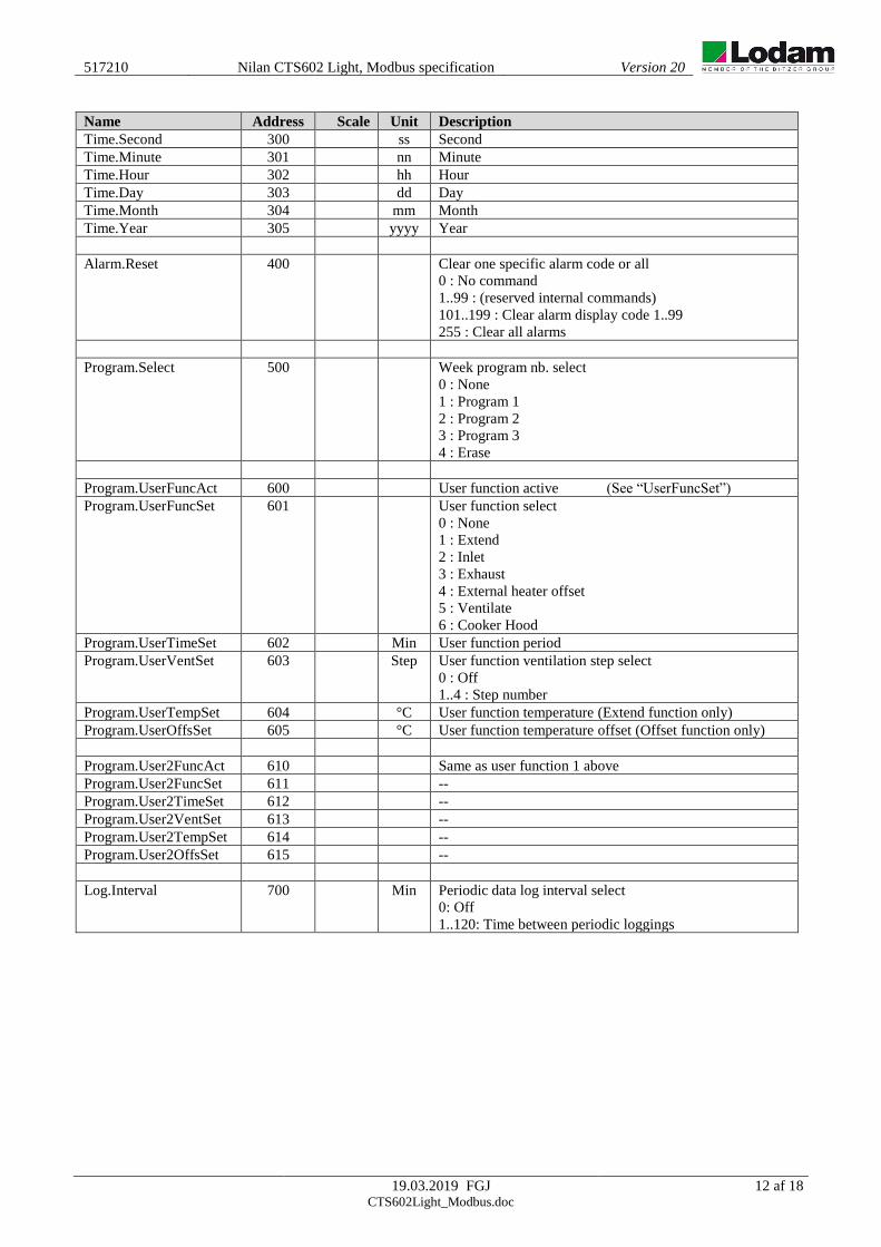
Name Address Scale Unit Description
Time.Second 300 ss Second
Time.Minute 301 nn Minute
Time.Hour 302 hh Hour
Time.Day 303 dd Day
Time.Month 304 mm Month
Time.Year 305 yyyy Year
Alarm.Reset 400 Clear one specific alarm code or all
0 : No command
1..99 : (reserved internal commands)
101..199 : Clear alarm display code 1..99
255 : Clear all alarms
Program.Select 500 Week program nb. select
0 : None
1 : Program 1
2 : Program 2
3 : Program 3
4 : Erase
Program.UserFuncAct 600 User function active (See “UserFuncSet”)
Program.UserFuncSet 601 User function select
0 : None
1 : Extend
2 : Inlet
3 : Exhaust
4 : External heater offset
5 : Ventilate
6 : Cooker Hood
Program.UserTimeSet 602 Min User function period
Program.UserVentSet 603 Step User function ventilation step select
0 : Off
1..4 : Step number
Program.UserTempSet 604 °C User function temperature (Extend function only)
Program.UserOffsSet 605 °C User function temperature offset (Offset function only)
Program.User2FuncAct 610 Same as user function 1 above
Program.User2FuncSet 611 --
Program.User2TimeSet 612 --
Program.User2VentSet 613 --
Program.User2TempSet 614 --
Program.User2OffsSet 615 --
Log.Interval 700 Min Periodic data log interval select
0: Off
1..120: Time between periodic loggings

517210
Nilan CTS602 Light, Modbus specification
Version 20
19.03.2019 FGJ 13 af 18 CTS602Light_Modbus.doc
Name Address Scale Unit Description
Control.Type 1000 Machine type select (factory setting)
Control.RunSet 1001 User on / off select (equal to ON/OFF keys)
0 : Off (user input functions can still activate operation)
1 : On
Control.ModeSet 1002 User operation mode select
0 : Off
1 : Heat (no cooling active)
2 : Cool (no heating active)
3 : Auto
4 : Service (readonly - write to register 1005)
Control.VentSet 1003 Step User ventilation step select
0 : Off
1..4 : Step number
Control.TempSet 1004 100 °C User temperature setpoint
Control.ServiceMode 1005 Service mode select
0 : Off
1 : Defrost
2 : Flaps
3 : Inlet
4 : Exhaust
5 : Compressor
6 : Heating
7 : Hot water
8 : Central heat
Control.ServicePct 1006 100 % Service mode capacity setpoint
Control.Preset 1007 Request preset to default settings
0 : Ready
1 : Standard (to factory defaults)
2 : Backup (to user file)
3 : Restore (from user file)
AirFlow.TestSelect 1102 Select a day for weekly air damper position self-test
The test runs at 10 in the morning on the selected day
Once enabled, the function cannot be deactivated
0: Off
1: Monday
2: Tuesday
3: Wednesday
4: Thursday
5: Friday
6: Saturday
7: Sunday
AirFlow.LastTestDay 1103 Date of last air damper position test
Bit word packed in DOS date format
(see IR 402 format)
AirFlow.TestState 1104 Actual air damper position test state
0: Off
1: Standby
2: Start (Set to Start to run manual test)
3: Closing
4: Opening
5: OK
6: Error

517210
Nilan CTS602 Light, Modbus specification
Version 20
19.03.2019 FGJ 14 af 18 CTS602Light_Modbus.doc
Name Address Scale Unit Description
AirFlow.FiltAlmType 1105 Air filter monitoring alarm type and period select
0: Pressure guard (input)
1: 30 days
2: 90 days
3: 180 days
4: 360 days
5: 70 days and pressure guard
AirTemp.CoolSet 1200 Cooling temperature setpoint select
0 : Off (No cooling allowed)
1 : Set + 0 °C (User setpoint plus 0 degrees)
2 : Set + 1 °C
3 : Set + 2 °C
4 : Set + 3 °C
5 : Set + 4 °C
6 : Set + 5 °C
7 : Set + 7 °C
8 : Set + 10 °C
AirTemp.TempMinSum 1201 100 °C Inlet temp. min. summer
AirTemp.TempMinWin 1202 100 °C Inlet temp. min. winter
AirTemp.TempMaxSum 1203 100 °C Inlet temp. max. summer
AirTemp.TempMaxWin 1204 100 °C Inlet temp. max. winter
AirTemp.TempSummer 1205 100 °C Summer/winter limit
AirTemp.NightDayLim 1206 100 °C Outdoor day temperature for night cooling activation
[0:Off, 20..40]
AirTemp.NightSet 1207 100 °C Free energy night cooling room setpoint
[10..30]
CentralHeat.HeatExtern 1800 100 °C External heating offset from room temperature setpoint
AirQual.RH_VentLo 1910 Step Humidity low winter step select
AirQual.RH_VentHi 1911 Step Humidity high step select
AirQual.RH_LimLo 1912 100 % Humidity limit for low ventilation
AirQual.RH_TimeOut 1913 min Humidity max. time on high ventilation
AirQual.CO2_VentHi 1920 Step CO2 high step select
AirQual.CO2_LimLo 1921 ppm CO2 limit for normal ventilation
AirQual.CO2_LimHi 1922 ppm CO2 limit for high ventilation
Name Address Scale Unit Description
User. UserMenuOpen 2002 Menu is open:
0=Closed, 1=Open, 2=No OFF key
DPT.DoCalibrate 2200 0,1 Calibrate DPT.
1: Start calibration

517210
Nilan CTS602 Light, Modbus specification
Version 20
19.03.2019 FGJ 15 af 18 CTS602Light_Modbus.doc
5.3.1 Display
Name Address Scale Unit Description
CentralHeat.HeatExtern 4000 100 °C Regulation deadband external room heating
-5.00°C – 5.00°C
AirFlow.WinterTemp 4002 °C Low outdoor temperature
-20°C - 10°C
AirFlow.WinerVent 4003 Fan speed at low outdoor temperature
0: OFF
1 - 3: Level
AirFlow.TestSelect 4004 Day for automatic test
0: OFF
1: Mo
2: Tu
3: We
4: Th
5: Fr
6: Sa
7: Su
AirHeat.Type 4005 After heating type
0: No additional heat
1: Electrical
2: Electric on binary relays
3: Water
AirHeat.Delay 4006 min Delay timer for after-heat activation
0-60 min.
AirTemp.TempMinSum 4007 100 °C Summer minimum supply air temperature
MinSum: 5.00-14.00
AirTemp.TempMaxSum 4008 100 °C Summer maximum supply air temperature
MaxSum: 5.00-25.00
AirTemp.TempMinWin 4009 100 °C Winter minimum supply air temperature
MinWin: 5.00-16.00
AirTemp.TempMaxWin 4010 100 °C Winter maximum supply air temperature
MaxWin: 5.00-35.00
AirTemp.RoomNZ 4011 100 Room temperature regulation deadband
0.20 – 10.00
AirTemp.TempRoomLow 4012 100 °C Low room temperature for stepwise reduced ventilation
0: OFF
1.00°C – 20.00°C
AirHeat.SelectSet 4013 After heating activation:
0: Off
1: On (No effect is AirHeat.Type (H4005) is 0.)

517210
Nilan CTS602 Light, Modbus specification
Version 20
19.03.2019 FGJ 16 af 18 CTS602Light_Modbus.doc
Name Address Scale Unit Description
Program.EditIndex 4030 Week program
Index: 0-41 (7 days multiply by 6 functions each day)
Program.EditPeriod 4031 Week program
Day index: 0-6 (0=Monday..)
Program.EditPeriodNx 4032 Week program
Next day index: 0-6 (0=Monday..)
Program.EditFunc 4033 Week program
Day function 0-5.
Program.EditTimeStar 4034 Week program
Start time: 0000 – 2345:
0800 = 8:00, 1215 = 12:15
Program.EditVent 4035 Week program
Fan settings: 0-4
0=Off,
1-4 Level
Program.EditTemp 4036 °C Week program
Temperature: 5°C - 50°C
Control.RestartMode 4040 External fire alarm auto reset
0: OFF
1: HPLP
2: CONTINUE
3: SELF_CLEAR
Control.PowerSave 4041 Enable power saving features
0: OFF
1: ON
Alarm.LogIndex 4050 Alarm log index
0 - 15
AirFlow.InletScale 4098 % Scaling of inlet fan control voltage for max. air volume
Range: 50..100
AirFlow.ExhaustScale 4099 % Scaling of exhaust fan control voltage for max. air volume
Range: 50..100

517210
Nilan CTS602 Light, Modbus specification
Version 20
19.03.2019 FGJ 17 af 18 CTS602Light_Modbus.doc
Name Address Scale Unit Description
AirFlow.InletSpd_1 4100 Inlet step 1 speed setup
Range: 20..100
AirFlow.InletSpd_2 4101 Inlet step 2 speed setup
Range: 20..100
AirFlow.InletSpd_3 4102 Inlet step 3 speed setup
Range: 20..100
AirFlow.InletSpd_4 4103 Inlet step 4 speed setup
Range: 20..100
AirFlow.ExhaustSpd_1 4104 Exhaust step 1 speed setup
Range: 20..100
AirFlow.ExhaustSpd_2 4105 Exhaust step 2 speed setup
Range: 20..100
AirFlow.ExhaustSpd_3 4106 Exhaust step 3 speed setup
Range: 20..100
AirFlow.ExhaustSpd_4 4107 Exhaust step 4 speed setup
Range: 20..100
AirQual.Type 4108 Enable Indoor Air Quality (IAQ) control function
Range: 0..2
0: OFF,
1: HUMIDITY,
2: HUM+CO2
Control.AnaOutType 4109 Heater output signal type (if not air channel type)
Range: 0..4
0: PERIOD
1: 0-10 V
2: 0/5/10 V
3: RELAY 3
4: RELAY 7
AirTemp.RoomResponse 4110 Room temperature controller response type
Select predefined or user adjustable parameters
Range: 0..3
0: SLOW,
1: NORMAL,
2: FAST,
3: USER

517210
Nilan CTS602 Light, Modbus specification
Version 20
19.03.2019 FGJ 18 af 18 CTS602Light_Modbus.doc
6. Communication example The sample shown below is a general Modbus communication example, and is not specific for this device.
Request: 0b041000000e75a4
Response: 0b041cffff0000095008b0e4a80014000b000108e108f1ffff000f0002fff39f8e
Request (Input register)
0x0b Slave addr 1 byte
0x04 Function code 1 byte
0x1000 Start addr 2 bytes
0x000e Quantity 2 bytes
0x75a4 CRC 2 bytes
Response
0x0b Addr 1 byte
0x04 Function code 1 byte
0x1c NB bytes of data 1 byte
0xffff Value1 2 bytes
0x0000 Value2 2 bytes
0x0950 Value3 2 bytes
0x08b0 Value4 2 bytes
0xe4a8 Value5 2 bytes
0x0014 Value6 2 bytes
0x000b Value7 2 bytes
0x0001 Value8 2 bytes
0x08e1 Value9 2 bytes
0x08f1 Value10 2 bytes
0xffff Value11 2 bytes
0x000f Value12 2 bytes
0x0002 Value13 2 bytes
0xfff3 Value14 2 bytes
0x9f8e CRC 2 bytes
Request: 0b03200000018f60
Response: 0b030200002045
Request (Holding register)
0x0b Slave addr 1 byte
0x03 Function code 1 byte
0x2000 Address 2 bytes
0x0001 Quantity 2 bytes
0x8f60 CRC 2 bytes
Response
0x0b Slave addr 1 byte
0x03 Function code 1 byte
0x02 Quantity 1 byte
0x0000 Value1 2 bytes
0x2045 CRC 2 bytes