nikolai nefedov, markku pukkila, raphael visoz, and...
TRANSCRIPT

1
Chapter 3
Radio aspectsInterference suppression by joint demodulation of cochannelsignals
PEKKA A. RANTA, MARKKU PUKKILANokia Research Center
Key words: Joint detection, channel estimation, training sequences, interference
Abstract: Inter-cell cochannel interference (ICCI) is an inherent problem in all cellularsystems due the necessity to reuse the same frequencies after a certain reusedistance. In GSM, the fact that the number of nearby cochannel interferers isrelatively small leads to a high probability of a dominant interferer (DI).Hence, suppression of DI alone provides substantial capacity improvement forGSM. The paper summarises different aspects of interference suppression byjoint demodulation of cochannel signals in the GSM system. The probabilityof DI is investigated by network simulations. Moreover, receiver algorithmsare described and receiver performance analysis is provided. In addition,requirements that the application of the technique poses for the GSM systemsare explained.
1. INTRODUCTION
Availability of the radio spectrum will be one of the main concerns in thefuture mobile radio systems as the number of mobile users is rapidlyincreasing and new data services are taken into use. In GSM, one of themost important factors limiting the cellular capacity is the cochannelinterference (CCI) originating from the surrounding cells using the samecarrier frequencies. Current GSM has already introduced a number ofadvanced radio access techniques such Discontinuous Transmission (DTx)and power control (PC) to minimise the problem of cochannel interference.In addition, GSM supports slow frequency hopping (FH) to overcome fastfading and provide interference diversity. [Mou92]

2 Pekka A. Ranta, Markku Pukkila
To improve the capacity of GSM even further it is a natural choice totake advantage of rapid development of digital signal processing techniquesand consider cochannel interference (CCI) suppression techniquesimplemented in receivers. The receivers’ improved susceptibility to CCIprovides means for lowering the frequency reuse distance in the network,that is, increase in the network spectrum efficiency. Alternatively, data ratescan be improved by reducing channel coding or just take the gain to increasequality of service. For example, in GSM packet radio (GPRS) and AdaptiveMultirate Codec (AMR) several channel coding rates are suggested allowingan individual terminal to benefit from higher data rate whenever it ispossible [ETSa,ETSb]. Another advantage of the IC-receiver is that it easesfrequency planning as the system becomes more robust against interference.This aspect may be important especially when implementing high capacitylow reuse cellular systems.
Interference cancellation techniques applicable in GSM can be dividedinto three categories: interference cancellation by joint (or multiuser)detection of cochannel signals, blind or semi-blind methods and adaptiveantennas. The first category of interest in this paper has been earlier studied,e.g., in [Gir93, Yos94, Wal95, Ran95a, Ran95b, Ran96, Edw96, Ran97a,Ran97b]. Most of the papers concentrate on the receiver techniques, but in[Ran95b, Ran96] capacity estimates are given showing potential capacitygain up to 60% in macrocells. A blind approach for GSM CCI reduction ispresented in [Ber96] using the knowledge of the constant envelope propertyof GMSK modulated signals. Another blind method has been introduced in[Ant97] based on usage of Hidden Markov Models. Application of neuralnetworks for CCI cancellation is proposed in several papers, e.g., [Che92,Che94, How93]. The last category of IC-techniques is probably the mostpowerful against interference and is based on the digital antenna arrayprocessing techniques with interference rejection combining (IRC) in thereceiver [Bot95, Win84, Fal93, Karl96, Esc97, Ran97c]. However, digitalantenna array processing techniques require multiple RF receivers for whichreason they are primarily applicable in the base station receivers. Theinterference cancellation by joint detection (JD/IC) requires only a singleantenna receiver making it an attractive alternative especially in the mobilereceivers.
In the conventional GSM receivers CCI is treated as additive Gaussiannoise. The fact that CCI is deterministic in nature and partly known, e.g.,modulation type and possible training sequence codes, makes multiuserdetection (MUD) or joint detection (JD) techniques feasible in GSMreceivers. In CDMA systems, MUD techniques are well-investigated for therejection of intra-cell interference which is the primary source of cochannelinterference in CDMA systems [Mos96]. In GSM, as the users areorthogonal within a cell, the problem is purely to combat inter-cell

#. Radio aspects 3
cochannel interference. In this case the number of cochannel signals is muchfewer and often a dominant interference (DI) exists which allows to reducethe baseband receiver complexity with only a reasonable performance loss.
In this paper different aspects of application of the JD/IC technique inthe GSM network will be summarised. First the problem of cochannelinterference is introduced in more detail and it is shown that the probabilityof DI can be relatively high in GSM networks. The receiver algorithm isdescribed based on the earlier contributions including detection algorithmand channel estimator with DI identification. The receiver complexity isdiscussed and complexity reduction methods are suggested. Theperformance of the technique is evaluated using a novel link simulatorintroduced in [Ran97b] using interference distribution information from anetwork simulator. The requirements of the JD/IC receiver from the systemspoint of view are considered in detail and the potential applications for thetechnique are enlightened. Finally, conclusions are drawn.
2. COCHANNEL INTERFERENCE
In mobile networks, the desire to maximise the number of availabletraffic channels in a given geographical area results to cochannelinterference (CCI) and adjacent channel interference (ACI) problems. In thispaper, we are interested in the removal of CCI only although in principle theremoval of ACI could be possible as well.
2.1 Frequency reuse
Cellular systems exploit the concept of frequency reuse meaning that thesame frequencies are repeated according to a certain reuse pattern or reusedistance. To maximise the network capacity [users/MHz/cell] we wish tominimise the number of cells in the reuse pattern. However, frequency re-usage causes inherent cochannel interference (CCI) problems in receivers.Hence, reuse pattern cannot be reduced without loss in the quality ofservice. Evidently, cellular capacity can be improved if receivers'susceptibility to the interference can be enhanced.
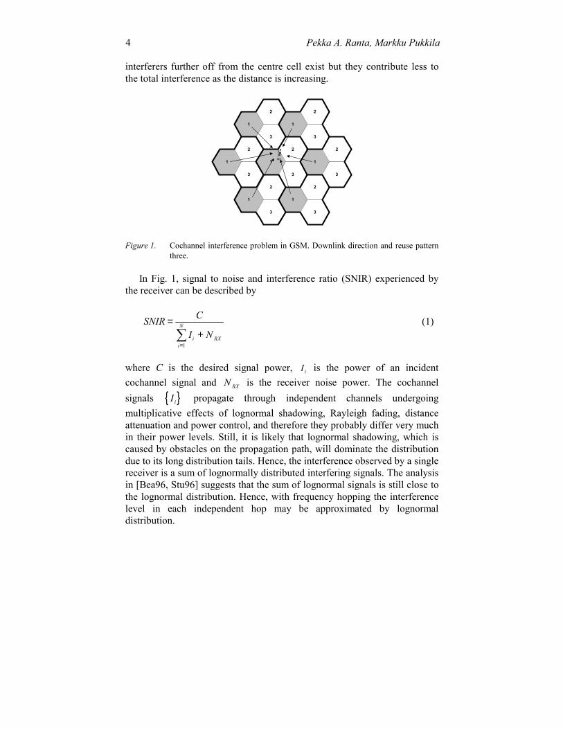
Fig. 1 below illustrates a co-channel communications situation in anidealised cellular network with hexagonal cells. In this case, the problem isdescribed in the downlink direction, that is, the mobile (MS) is the receivingend. In GSM, users are orthogonal within a cell, thereby the cochannelinterference purely originates from the surrounding cells and the number ofCCI sources is rather low, i.e. six in this case. In a real network, more
4 Pekka A. Ranta, Markku Pukkila
interferers further off from the centre cell exist but they contribute less tothe total interference as the distance is increasing.
3
3
2
1
3
2
2
1
1
3
3
2
1
1
2
1 1
22
3 3
3
MS
Figure 1. Cochannel interference problem in GSM. Downlink direction and reuse patternthree.
In Fig. 1, signal to noise and interference ratio (SNIR) experienced bythe receiver can be described by
SNIR C
I Ni RXi
N=+
=�
1
(1)
where C is the desired signal power, Ii is the power of an incidentcochannel signal and N RX is the receiver noise power. The cochannelsignals { }Ii propagate through independent channels undergoingmultiplicative effects of lognormal shadowing, Rayleigh fading, distanceattenuation and power control, and therefore they probably differ very muchin their power levels. Still, it is likely that lognormal shadowing, which iscaused by obstacles on the propagation path, will dominate the distributiondue to its long distribution tails. Hence, the interference observed by a singlereceiver is a sum of lognormally distributed interfering signals. The analysisin [Bea96, Stu96] suggests that the sum of lognormal signals is still close tothe lognormal distribution. Hence, with frequency hopping the interferencelevel in each independent hop may be approximated by lognormaldistribution.
#. Radio aspects 5
2.2 Existence of dominant interferer
In GSM, a dominant interferer (DI) likely exists since the number ofnearby cochannel interferers is rather small, for example, in the case ofomnidirectional cells the nearest cochannel tier includes six cells (see Fig.1). This number is further limited to two or three by cell sectorisation orusage of adaptive antennas. In addition, discontinuous transmission (DTx)as well as fractional loading cause that the interferers do not likely transmitsimultaneously. Furthermore, independent distance attenuation, shadowing,Rayleigh fading and power control make the power levels of the receivedsignals probably very much different from each other.
Obviously, cancellation of DI alone can improve the receiverperformance significantly with the advantage of remarkably lowercomplexity than suppressing more interfering signals. When channelintersymbol interference (ISI) is moderate, it is also practical to considerjoint demodulation of more than two cochannel signals. The efficiency ofthe DI cancellation is naturally dependent on the dominant to rest ofinterference ratio (DIR) in addition to the signal to noise and interferenceratio (SNIR). In mathematical terms DIR can be expressed as
DIRI
I I N
dom
i dom RXi
K=− +
=�
1
(2)
where Idom is the dominant among all the interfering signals, i.e.,I I I Idom N= max( , ,..., )1 2 and N RX the receiver noise power. In the furtheranalysis it is assumed that noise power is negligible compared to the rest ofinterference.
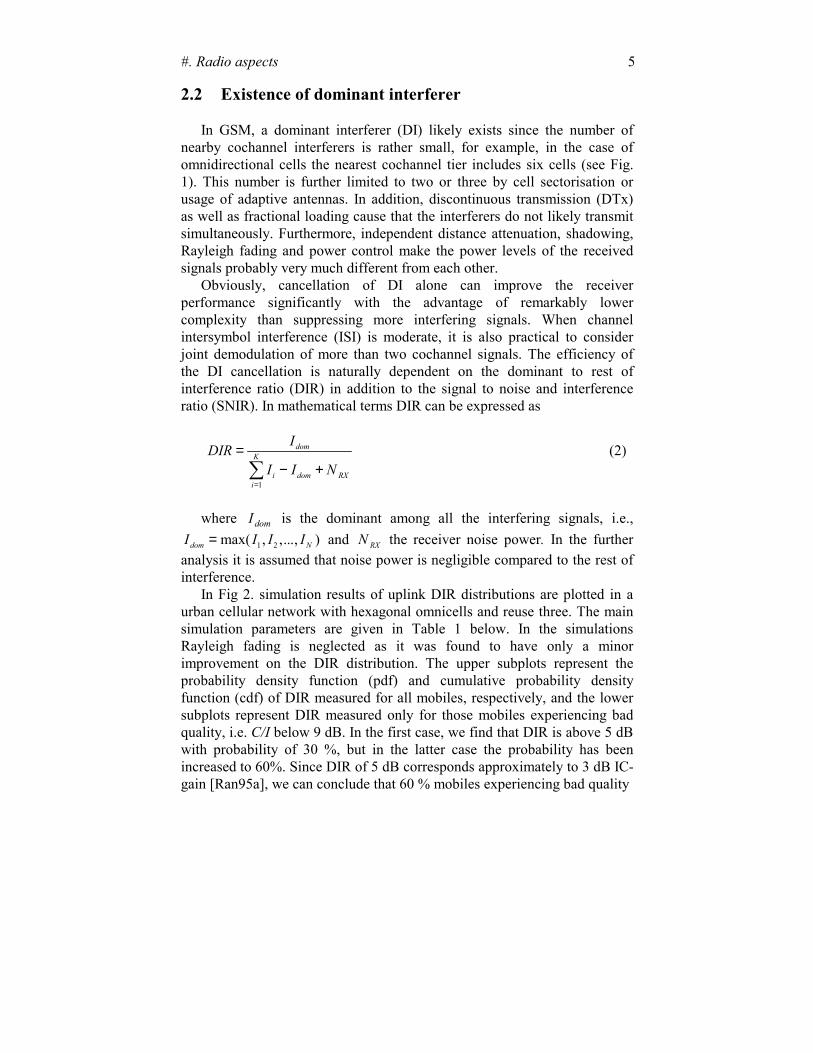
In Fig 2. simulation results of uplink DIR distributions are plotted in aurban cellular network with hexagonal omnicells and reuse three. The mainsimulation parameters are given in Table 1 below. In the simulationsRayleigh fading is neglected as it was found to have only a minorimprovement on the DIR distribution. The upper subplots represent theprobability density function (pdf) and cumulative probability densityfunction (cdf) of DIR measured for all mobiles, respectively, and the lowersubplots represent DIR measured only for those mobiles experiencing badquality, i.e. C/I below 9 dB. In the first case, we find that DIR is above 5 dBwith probability of 30 %, but in the latter case the probability has beenincreased to 60%. Since DIR of 5 dB corresponds approximately to 3 dB IC-gain [Ran95a], we can conclude that 60 % mobiles experiencing bad quality
6 Pekka A. Ranta, Markku Pukkila
−20 0 20 400
0.01
0.02
0.03
0.04
0.05
0.06PDF of DIR
DIR [dB]−20 0 20 400
20
40
60
80
100CDF of DIR
DIR [dB]
−20 0 20 400
0.01
0.02
0.03
0.04
0.05PDF of DIR (C/I<9 dB)
DIR [dB]−20 0 20 400
20
40
60
80
100CDF of DIR (C/I<9 dB)
DIR [dB]
Figure 2. DIR distributions (pdf and cdf) for all mobiles (up) and for mobiles withC/I<9dB (down).
can achieve more than 3 dB IC-gain. Note that the DIR distribution wouldbecome even more favourable in case of sectorised cells.
In addition to chosen radio access techniques (DTx, PC, etc. ), the DIRratio depends on the environmental parameters such as the propagationindex and shadow parameter. In practical network planning, different longterm propagation characteristics for each of the cochannel signals andirregularly placed cell sites often leads to the presence of a dominantinterfering signal. In microcellular environment, street crossings are knownto be the most difficult places from the interference point of view. In[Ran97a] it is shown that the DI cancellation is a very powerful method tosolve the interference problem in microcell street crossings.
Table 1. Parameter values used in the simulation of a GSM mobile network.
reuse 3number of interferers 18duplex direction uplinkpropagation index 4std of lognormal shadowing 8 dBpower control dynamicity 30 dBpower control error lognormal with std 5 dBhandover margin 3 dBbase station activity 50%

#. Radio aspects 7
3. RECEIVER ALGORITHMS
Fig. 3 above depicts the cochannel communications system modelconsidered in this section. It consist of N transmitters with independent timevarying channels, additive white Gaussian noise source, receiver filter, jointchannel estimator (JCE) and joint detector (JD). As shown by the figure,joint detector (JD) employs directly the channel estimates provided by thejoint channel estimator (JCE). The joint detector can provide, although it isnot necessary, symbol estimates of the each cochannel bit stream in theprocess. In case of DI cancellation there are only two signals in the processi.e. N=2. In the following sections we explain the JCE and JD blocks indetail, but we start explaining the format of the received signal that isnecessary for understanding the basis of joint signal detection.
3.1 Signal format
3.1.1 Burst structure
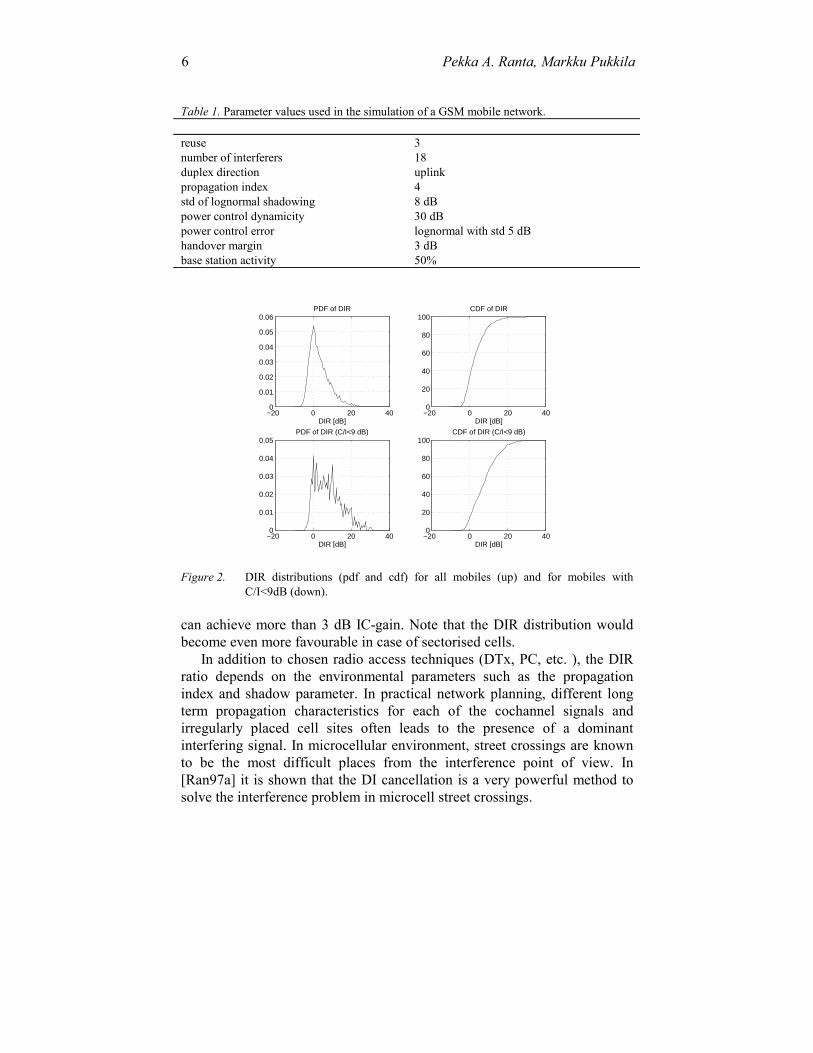
In Fig. 4. the GSM TCH burst is described containing three zero symboltail bits in the beginning and end, training sequence of 26 bits in the middleand two data blocks of 58 bits around the training sequence. One bit in theboth sides of training sequence (two bits in total) is reserved for signallingpurposes. The tail bits are used by the demodulator to initialise and finishthe detection process. The training sequence is used for channel estimationenabling signal equalisation and coherent detection. [ETSc]
TRX 1 c1(t)s1(t-kT)
n(t)
NOISE
RXFILTER
JOINTCHANNEL
ESTIMATOR
JOINTDETECTORrK
rK
hL,N
aK;NTRX 2 c2(t)s2(t-kT)
TRX N cN(t)sN(t-kT)
Figure 3. Cochannel communications system and receiver model
8 Pekka A. Ranta, Markku Pukkila
The training sequence consists of a reference sequence of length 16 bits,five guard symbols in the both sides of the reference sequence or,equivalently, ten guard bits before the reference sequence. The purpose ofthe guard bits is to cover the time of intersymbol interference and timesynchronisation errors. In GSM, eight distinct training sequences arespecified from which four sequences have seven zeros in their periodicautocorrelation function in both sides of the main peak and the other foursequences have six zeros around the main autocorrelation peak. Thisproperty enables estimation of at least five channel taps just based on thestrict correlation of the known and received training sequence. [ETSc]
3.1.2 Modulation and channel
GSM system employs non-linear GMSK modulation which is a constantenvelope modulation and thereby does not pose as tight requirement poweramplifier linearity as its linear PSK and QAM correspondents. Nevertheless,GMSK can be approximated as a linear modulation method since themodulator pulse can be constructed as a sum of finite number of amplitudemodulated pulses [Lau86]. From this point of view GMSK can been seen asBinary Offset QAM, i.e. Offset QPSK, with a different pulse shape. In thefollowing presentation we use this approximation of GMSK and take it as alinear modulation method with binary modulation alphabets {-1,+1}.Although the presentation is limited to binary transmission, the sameequations can be easily extended to higher level modulations.
The transmitted waveform can be expressed in the complex basebandform as
( )s t a g t kTkk
K
( ) = −=�
1
(1)
1 1 1 00 0 0 1 0 1 1 0 1 1 1 0 1 1 1 1 0
taildata training data
guard bits reference bits
tail
Figure 4. An example of GSM burst
#. Radio aspects 9
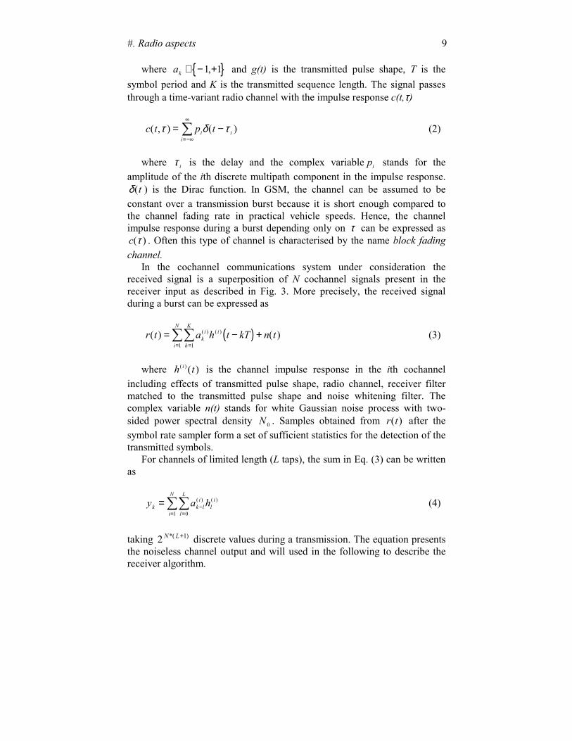
where { }ak ∈ − +1 1, and g(t) is the transmitted pulse shape, T is thesymbol period and K is the transmitted sequence length. The signal passesthrough a time-variant radio channel with the impulse response c(t,τ)
c t p ti ii
( , ) ( )τ δ τ= −=−∞
∞
� (2)
where τ i is the delay and the complex variable pi stands for theamplitude of the ith discrete multipath component in the impulse response.δ(t ) is the Dirac function. In GSM, the channel can be assumed to beconstant over a transmission burst because it is short enough compared tothe channel fading rate in practical vehicle speeds. Hence, the channelimpulse response during a burst depending only on τ can be expressed asc( )τ . Often this type of channel is characterised by the name block fadingchannel.
In the cochannel communications system under consideration thereceived signal is a superposition of N cochannel signals present in thereceiver input as described in Fig. 3. More precisely, the received signalduring a burst can be expressed as
( )r t a h t kT n tki i
k
K
i
N
( ) ( )( ) ( )= − +==��
11(3)
where h ti( ) ( ) is the channel impulse response in the ith cochannelincluding effects of transmitted pulse shape, radio channel, receiver filtermatched to the transmitted pulse shape and noise whitening filter. Thecomplex variable n(t) stands for white Gaussian noise process with two-sided power spectral density N 0 . Samples obtained from r t( ) after thesymbol rate sampler form a set of sufficient statistics for the detection of thetransmitted symbols.
For channels of limited length (L taps), the sum in Eq. (3) can be writtenas
y a hk k li
li
l
L
i
N
= −==��
( ) ( )
01
(4)
taking 2 1N L*( )+ discrete values during a transmission. The equation presentsthe noiseless channel output and will used in the following to describe thereceiver algorithm.
10 Pekka A. Ranta, Markku Pukkila
3.2 Joint detection
3.2.1 Joint MLSE Detection
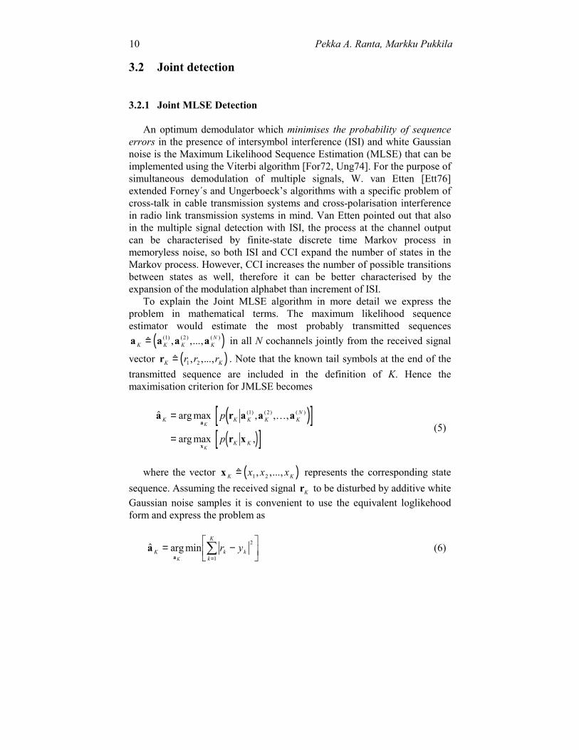
An optimum demodulator which minimises the probability of sequenceerrors in the presence of intersymbol interference (ISI) and white Gaussiannoise is the Maximum Likelihood Sequence Estimation (MLSE) that can beimplemented using the Viterbi algorithm [For72, Ung74]. For the purpose ofsimultaneous demodulation of multiple signals, W. van Etten [Ett76]extended Forney´s and Ungerboeck’s algorithms with a specific problem ofcross-talk in cable transmission systems and cross-polarisation interferencein radio link transmission systems in mind. Van Etten pointed out that alsoin the multiple signal detection with ISI, the process at the channel outputcan be characterised by finite-state discrete time Markov process inmemoryless noise, so both ISI and CCI expand the number of states in theMarkov process. However, CCI increases the number of possible transitionsbetween states as well, therefore it can be better characterised by theexpansion of the modulation alphabet than increment of ISI.
To explain the Joint MLSE algorithm in more detail we express theproblem in mathematical terms. The maximum likelihood sequenceestimator would estimate the most probably transmitted sequences
( )a a a aK K K KN
� , ,...,( ) ( ) ( )= 1 2 in all N cochannels jointly from the received signal
vector ( )rK Kr r r� , ,...,= 1 2 . Note that the known tail symbols at the end of thetransmitted sequence are included in the definition of K. Hence themaximisation criterion for JMLSE becomes
( )[ ]( )[ ]
� arg max , , ,
arg max ,
( ) ( ) ( )a r a a a
r x
a
x
K K K K KN
K K
K
K
p
p
=
=
1 2�
(5)
where the vector ( )x K Kx x x� , ,...,= 1 2 represents the corresponding statesequence. Assuming the received signal rK to be disturbed by additive whiteGaussian noise samples it is convenient to use the equivalent loglikehoodform and express the problem as
� arg minaa
K k kk
K
K
r y= −�
��
�
��
=�
2
1
(6)

#. Radio aspects 11
where yk is defined by Eq. (4). The equation returns the minimum sum ofEuclidean distances over all possible sequences. It is well known that thisminimisation problem can be solved by the Viterbi algorithm using therecursion
J J r yk kn
k kn
k k( ) ( )( ) ( )a a= + −− −1 12 (7)
where the term J n Nk kn
− − =1 1 1 2( ), , , ,( )a � presents the survivor path metric atthe previous stage in the trellis. In fact, the path metrics of the single signaldetection is identical to Eq. (7) using yk in Eq. (4) with N equal to 1. Inother words, the difference is that in every symbol period JMLSE weightsthe symbols ( )a a ak k k
N( ) ( ) ( ), , ,1 2� jointly instead of ak
( )1 alone.
3.2.2 Joint symbol-by-symbol MAP detection
In difference to MLSE detection minimising the sequence errorprobability, the objective of the Maximum a Posteriori (MAP) algorithm isto minimise the probability of a single symbol error by estimating aPosteriori probabilities (APP) of states and transitions of the Markov sourcefrom the received signal sequence. Type-I MAP algorithm introduced byChang and Hancock [Cha66] uses the information of the whole receivedsequence to estimate a single symbol probability. In other words, type-IMAP algorithm selects the symbol { }ak
i( ) ,∈ − +1 1 at time instant k whichmaximises the following APP
( )[ ]� arg max( ) ( )( )
a p aki
aki
Kki
= r (8)
where �( )aki is the symbol estimate in the cochannel i of interest. Type-II
MAP algorithm introduced by Abend and Fritchman [Abe70] instead usesall the information from the previous samples but only a limited amount ofthe future samples determined by a fixed lag decision delay. MAP type-IIalgorithm maximises the following a posteriori probability
( )[ ]� arg max( ) ( )( )
a p aki
aki
k Dk
i= + r (9)
where ( )rk D k k k Dr r r+ + +=� , ,...,1 and D stands for the decision delay. When thedecision delay is increased, the performance of the type-II MAP algorithmapproaches to that of the type-I MAP algorithm [Li95].

12 Pekka A. Ranta, Markku Pukkila
The MAP algorithms require multiplicative accumulation of thetransition probabilities which is not desirable in ASIC implementation whilein DSP implementation the cost of multiplication is much less significant.Nevertheless, this problem can be avoided with only a minor performanceloss by computing the metric of the MAP algorithm in log-domain leading toadditive accumulation of path metrics [Li95, Rob95]. The complexity ofthese algorithms approaches to that of Viterbi algorithm. The mainadvantage of MAP algorithms over the Viterbi algorithm is more reliabletransfer of soft information for the channel decoder.
3.3 Joint channel estimation
The estimation of the channel impulse response for both desired anddominant interfering signals is a crucial matter for joint detection. To beable to compute yk in Eq. (7) or the probabilities in (8) and (9), knowledgeof the channel impulse response of all jointly demodulated cochannels isrequired. In the conventional GSM receiver, channel estimation is based ona priori known training sequences as explained in Sec. 3.1. Evidently, JCEcan also exploit the knowledge of training sequences carried by cochannelsignals. However, the cross-channel interference between cochannel signalsmakes the task very challenging.
A most straightforward method to solve the channel estimates fastly,reliably and accurately is to use a one-shot channel estimation based on asolution of a system of linear equations [Ste94, Ran95a, Puk97] posing twoadditional constraints for the system:
1. Training sequences in each cochannel should be receivedsimultaneously (Fig. 5) to be able to remove the cross-channelinterference.
2. Training sequences should be unique with good cross-correlationproperties at least in the closest cochannels.
The first requirement is not fully strict in the sense that some asynchronismcan be allowed depending on the reference and guard period lengths of thetraining sequence. The second requirement implies some sort of codesequence planning and selection of best training sequences among theexisting ones or totally new sequence sets for GSM. These requirements aremore thoroughly discussed in Sec. 5.

#. Radio aspects 13
Asynchronous system
To perform joint channel estimation in the asynchronous system it isnecessary to use semi-blind channel estimation methods which means thatthe available training sequence information is also utilised. In this case itwould be beneficial to maximise the training sequence length to get a betterprotection for cross-channel interference. In any case, the performance inthe asynchronous case will be worse than in the synchronous mode not onlybecause of the blind channel estimation but since the interference maychange during a transmission burst.
3.3.1 Basic algorithm
Suppose there are N synchronous co-channels, i.e., the primary user andN-1 interferers each having a different training sequence and a differentchannel. Denote the N radio channels by
h L n n n L nTh h h n N, , , ,� ( , , , ) , , ,..., ,= =0 1 1 2�
each of length (L+1) with complex channel tap weights. Collect the channelimpulse responses into the vector h as follows
h h h h� ( , , , ), , ,= LT
LT
L NT T
1 2 � .
The number of parameters above is thus N L× +( )1 . The training sequenceof the nth channel consisting of the guard and reference sequence bits isdenoted by
data data
data training
guard reference
interference
desired signal
data
training data
data
Figure 5. Two cochannel bursts received simultaneously

14 Pekka A. Ranta, Markku Pukkila
m n n n P L nTm m m n N� ( , , , ) , , , ,, , ,= =+ −0 1 1 1 2� �
with L+P elements { }mp n, ,∈ − 1 1 , where L is the number of the guard bitsimplying that maximum of L+1 taps can be estimated and P is the length ofthe reference sequence.
The received signal corresponding to the reference bits is then
y Mh n= + (10)
where n represents Gaussian noise samples with the covariance matrix R ,and the matrix M M M M= ( , ,..., )1 2 N includes the transmitted trainingsequences organised to the matrices M n , n=1,2...,N, as follows:
M n
L n n n
L n n n
P L n P n P n
m m m
m m m
m m m
�
, , ,
, , ,
, , ,
=
�
�
�������
�
�
�������
+
+ − −
�
�
�
�
� �
1 0
1 2 1
1 1
.
The maximum likelihood channel estimate is given by
� ( )h M R M M R yMLH H= − − −1 1 1 , (11)
and assuming that the noise in Eq. (10) is white it reduces to
� ( )h M M M yMLH H= −1 . (12)
The result is the well-known solution of Wiener-Hopf equation in matrixform. Note that the Eq. (12) is equivalent to the conventional channelestimator if N is equal to 1.
3.3.2 Training sequences
The product M MH in Eq. (12) is the correlation matrix of all sequencesincluding both auto- and cross-correlation terms. Unfortunately, theinversion of the product M MH leads to the noise enhancement which limitsthe performance of a particular sequence set. The SNR degradation dce can
#. Radio aspects 15
be directly obtained from the diagonal elements of the matrix ( )M MH −1 andis given by [Stei94]
( ){ }d dBceH/ log= ⋅ +�
�����
−10 110
1tr M M . (13)
In the current GSM, the training sequences have ideal periodic auto-correlation functions over six or seven symbol shifts depending on thesequence which means that the noise enhancement is avoided in case ofsingle signal channel estimation. For JCE, the noise enhancement cannot betotally avoided, as the cross-correlation properties are also counted. In theGSM training sequence set, the cross-correlation performance of the pairfour and five from [ETSc] is very poor. A reason for this is that thesequences turn out to be reciprocal of each other.
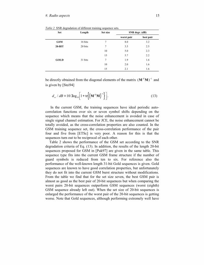
Table 2 shows the performance of the GSM set according to the SNRdegradation criteria of Eq. (13). In addition, the results of the length 20-bitsequences proposed for GSM in [Puk97] are given in the same table. Thissequence type fits into the current GSM frame structure if the number ofguard symbols is reduced from ten to six. For reference also theperformance of the well-known length 31-bit Gold sequences is given. Goldsequences are known to have good correlation properties, but unfortunatelythey do not fit into the current GSM burst structure without modifications.From the table we find that for the set size seven, the best GSM pair isalmost as good as the best pair of 20-bit sequences but when comparing theworst pairs 20-bit sequences outperform GSM sequences (worst (eighth)GSM sequence already left out). When the set size of 20-bit sequences isenlarged the performance of the worst pair of the 20-bit sequences is gettingworse. Note that Gold sequences, although performing extremely well have
Table 2. SNR degradation of different training sequence sets.Set Length Set size SNR degr. (dB)
worst pair best pair
GSM 16 bits 7 8.0 3.2
20-BIT 20 bits 7 3.5 2.5
10 5.0 2.3
15 5.7 2.2
GOLD 31 bits 7 1.9 1.6
10 2.0 1.6
15 2.1 1.6
16 Pekka A. Ranta, Markku Pukkila
the relative advantage of the longer sequence length as well as the largerbasic set.
3.3.3 Identification of the dominant interferer
Identification of the dominant interfering signal on a burst-by-burst basisis mandatory in the DI cancellation especially with frequency hopping as theinterference source will change from burst to burst. The identification canbe accomplished as an integral part of the channel estimation process takingadvantage of the different training sequences allocated to cochannels. Anoptimum DI identification method would estimate all the cochannels jointlyusing Eq. (12) and select the most powerful interfering signal. However, dueto the fact that single valued solutions for Eq. (12) do not exist when thenumber of estimated channel parameters exceeds reference sequence length,this approach may not be feasible in GSM. For example, in case of fourestimated channel taps, only four or five cochannels can be estimatedsimultaneously for reference sequence lengths of 16 and 20, respectively.
The most straightforward suboptimum method for DI identification is tomeasure the signal power after a filter bank matched to transmitted trainingsequences and select the one with the largest output power. However, due tothe still rather strong cross-correlation values and relatively high powerdynamics of the cochannel signals this approach may not provide asatisfactory performance. A more efficient method described in [Puk97]called pairwise channel estimation (PCE) method considers only twosequences at a time in computing Eq. (12) with the first sequence beingalways the desired signal training sequence, which is known a priori, whilethe second sequence is a candidate DI training sequence. All the interferencetraining sequences are scanned and finally the best pair is selected eitherbased on direct power estimation from the impulse responses or MSEcriterion, i.e. the pair which minimises the residual signal
ε = −y Mh�2
(14)
where M and �h include information of two sequences at a time. Theadvantage of the PCE method is that the cross-channel interference can beremoved between two sequences.
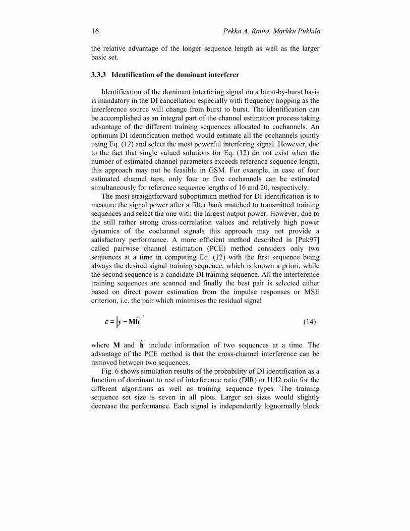
Fig. 6 shows simulation results of the probability of DI identification as afunction of dominant to rest of interference ratio (DIR) or I1/I2 ratio for thedifferent algorithms as well as training sequence types. The trainingsequence set size is seven in all plots. Larger set sizes would slightlydecrease the performance. Each signal is independently lognormally block

#. Radio aspects 17
fading and experiences fixed ISI in each block. Channel taps are (0.7479,0.2441, 0.008) one symbol from each other. A lognormal power distributionhas been used for interfering signals I1 and I2 and they are varyingindependently burst-by-burst basis modelling the frequency hopping (seeSec. 2).
It turns out that the PCE method performs significantly better than theother methods. The reason for this may be that the signals excluded in thechannel estimation act as a coloured noise which can be better combated bythe MSE criterion using also the phase information of channel taps. WithMSE criterion DI can be identified with 90-100% probability if DIR isgreater than 5 dB. The performance somewhat varies with differentsequence sets. The performance of the matched filter method is quite stablefor all sequence types, unlike the performance of the PCE method dependsvery much on the used sequence set. Note that the curves present theaverage performance of all sequences in a subset, modelling the case offrequency hopping. It should be remembered that for different sequencepairs the performance may vary, which may be of interest, e.g., in non-frequency hopping cases.
0 5 10 15 200
0.2
0.4
0.6
0.8
120−BIT subset 7
prob
abili
ty
I1 / I20 5 10 15 20
0
0.2
0.4
0.6
0.8
1GOLD subset 7
prob
abili
ty
I1 / I2
pair / residual pair / power est.matched filter
0 5 10 15 200
0.2
0.4
0.6
0.8
1GSM subset 7
prob
abili
ty
I1 / I2
Figure 6. The probability of DI identification as a function of DIR i.e. I1/I2
18 Pekka A. Ranta, Markku Pukkila
3.4 Receiver complexity
3.4.1 Joint Detector
For joint detector, the main computational burden comes from theincrease in the trellis size and transitions per state in the Viterbi algorithm.The number of trellis states is increasing exponentially by 2 NL and numberof transitions per state is increasing as 2N , where N is the number ofcochannel signals in process and L is the channel memory length. To keepthe complexity of the receiver tolerable, the advantage of suppression of DIalone is clear as N=2.
Compared to the conventional receiver, the trellis size of the Viterbialgorithm expands from 8 to 64 states or 16 states to 256 states in case of DIcancellation. The trellis size of 64 (4 channel taps per signal) is sufficient inurban areas and in rural, micro and indoor areas even a lower number oftrellis states may suffice. In addition, the number of transitions per trellisstate is increased from two to four compared to the current GSM receiver.The impact of this is that 1) number of compare-select operations per state isincreased from one to three and 2) number of branch metric computations isdoubled. Fortunately, the computation of a single branch metric value do notrequire extra processing power thanks to the block fading channel whichallows us to precompute a look-up table of the possible channel outputvalues (Eq. (4)) for a burst. Nevertheless, factor of eight to ten increase incomplexity may be expected when updating the current GSM 16-stateMLSE equaliser with 64-state JMLSE receiver implying that ASIC may bethe most feasible approach for implementation.
In the literature a number of proposals have been made to reduce thecomplexity of the Viterbi equaliser. The most straightforward is to use thedelayed decision feedback sequence estimation (DDFSE) truncating thechannel impulse response and using only the truncated part to construct theViterbi trellis [Duel88, Eyu88]. The feedback part is used in the branchmetrics computation. The complexity increase of this algorithm is onlymoderate with increasing number of channel taps. However, DFE structureis known to have difficulties in non-minimum phase channels, for whichreason a prefilter turning the channel into minimum phase might be required[Mou94]. A method to reduce trellis states is to combine those states closeto each other [Wal95]. Another method used in [Clar78] proposes to excludethe paths with low probability and keep only a fixed amount of paths forfurther processing.

#. Radio aspects 19
3.4.2 Joint channel estimation
JCE increases the complexity of the receiver, but it can be reducedsignificantly when the product of the first three terms in Eq. (12) are kept inthe receiver memory. In addition, the fact that the product consists of realvalued terms can exploited when computing the complex algebra. Roughly,JCE doubles the computational burden compared to the single channelestimation. However, DI identification process increases the complexity bythe factor number of training sequences minus one since the channelestimation has to be repeated for each desired signal and interference signalpair.
3.5 Other receiver issues
The problem of frequency offset between cochannel carriers may causedegradation in the receiver performance. The accuracy of BS frequencyreference are 45 Hz for GSM and 90 Hz for DCS1800. In addition theDoppler shift might be in opposite directions for the interference and desiredsignal. This may result to maximum of 200-300 Hz frequency offset in theworst case which can be compensated by standard channel trackingalgorithms, if necessary.
4. PERFORMANCE ANALYSIS
4.1 Simulation model
The DIR distribution has a major effect on the performance of the DIcancellation, therefore we have designed a novel link simulator in theperformance analysis introduced in [Ran97b]. As shown in Fig. 7, thesimulator includes a large number of interfering signals and each of themundergoes independently the multiplicative effects of multipath channel(fast fading) and lognormal fading. Both fading types are assumed to beindependent from burst to burst modelling behaviour of ideal frequencyhopping. The link simulator allows to evaluate and test following aspectsimportant for joint detection:– IC-gain relative to the conventional receiver– DI identification algorithm– required size of training sequence– effect of the DIR distribution on IC-gain– effect of frequency hopping

20 Pekka A. Ranta, Markku Pukkila
In case of hexagonal omnicell layout, the mean value of the lognormaldistribution is defined by the average distance attenuation from interferingmobiles to the centre cell or vice versa. The standard deviation of thelognormal shadowing is obtained from the network simulator introduced inSec. 2.2 with parameters introduced in Table 1 except no DTX is used. To justify our assumption of lognormal interference, Fig. 8 plots theinterference distributions originating from a single cochannel cell for tiers 1,2 and 3. It can be seen that the distributions look fairly Gaussian with someasymmetricity. The standard deviations of all interfering signals are ca. 11dB and the mean value is proportional to the distance from the centre cell.
CHANNELTRX
AWGN
RX
I1
CH1
TRX1 I2
CH2
TRX2 IN
CHN
TRXN
COCHANNEL INTERFERENCE
Figure 7.Lognormal fading simulation model
−70 −60 −50 −40 −30 −20 −10 0 10 200
0.02
0.04
0.06
0.08
0.1
0.12
0.14
tier 1tier 2tier 3
Distribution of a signal originating from a cochannel
Power [dB]
Pro
babi
lity
reuse = 3slope = 4std = 8 dB
mean 2 =−28.8mean 1 =−19.2mean 2 =−28.8mean 3 =−31.2std 1 =11.13std 2 =10.83std 3 =10.81
Figure 8. Interference distribution of a single cochannel interferer in tiers 1, 2,and 3.
#. Radio aspects 21
Accordingly, these values are adopted in the link simulator. Note that alower base station activity (DTX, load) will increase the standard deviationwhich can be controlled in the link simulator by randomly switching on/offinterference bursts. The wideband channel model is Typical Urban and theGSM transmission parameters are used in all simulations [ETSc].
4.2 Results
In this section we compare the performance of different trainingsequence sets and the PCE DI identification algorithm. In addition, weinvestigate the effect of base station activity factor and cochannelasynchronism as well as the gain of suppressing two interferers. In allsimulations uncoded BER is evaluated.
4.2.1 Training sequence performance
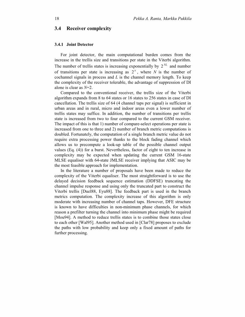
The performance of different training sequence sets is shown in Fig. 9.Seven different training sequences are allocated for 18 interferers such thatthe closest cochannel tier has different training sequence codes. As DI ischanging randomly, the shown curve is an average performance of allsequences. We can see that the GSM sequences are 1.3 dB worse than 20-bitsequences, and furthermore, the Gold sequences do not seem to improve theperformance very much. Results also indicate that training sequence set sizeof seven is sufficient in the omnicell case. In case of sectorised cells, even alower number of training sequences might suffice.
Figure 9. Performance of different training sequences
22 Pekka A. Ranta, Markku Pukkila
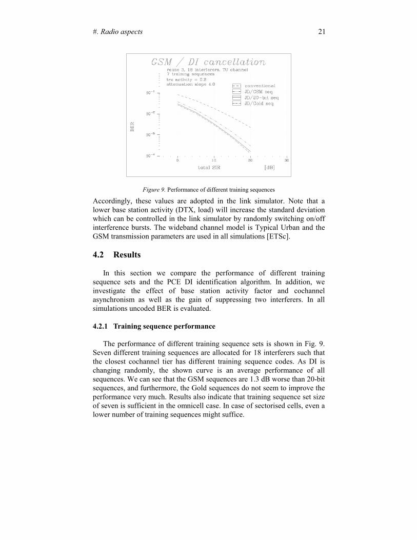
4.2.2 Performance of the DI identification algorithm
The performance of the PCE algorithm (see Sec. 3.3.3) is compared tothe perfect DI identification in Fig. 10. We can see that there is negligibleperformance loss because of the estimation of DI. An explanation for thisextremely good performance is that DI is very probably found when DIR > 5dB and for lower values of DIR the IC-gain would be small anyway.
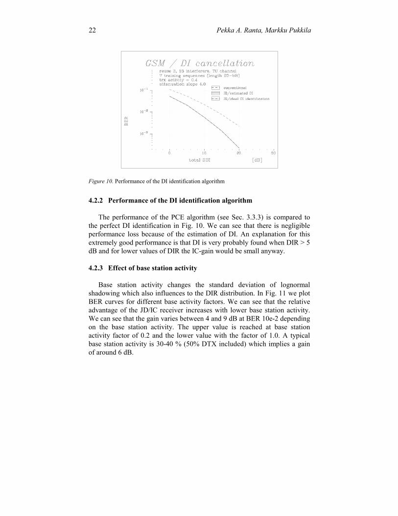
4.2.3 Effect of base station activity
Base station activity changes the standard deviation of lognormalshadowing which also influences to the DIR distribution. In Fig. 11 we plotBER curves for different base activity factors. We can see that the relativeadvantage of the JD/IC receiver increases with lower base station activity.We can see that the gain varies between 4 and 9 dB at BER 10e-2 dependingon the base station activity. The upper value is reached at base stationactivity factor of 0.2 and the lower value with the factor of 1.0. A typicalbase station activity is 30-40 % (50% DTX included) which implies a gainof around 6 dB.
Figure 10. Performance of the DI identification algorithm
#. Radio aspects 23
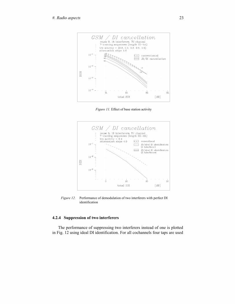
4.2.4 Suppression of two interferers
The performance of suppressing two interferers instead of one is plottedin Fig. 12 using ideal DI identification. For all cochannels four taps are used
Figure 11. Effect of base station activity
Figure 12. Performance of demodulation of two interferers with perfect DIidentification
24 Pekka A. Ranta, Markku Pukkila
in the detector corresponding to 512 trellis states. We can see that the gain isonly 1 dB indicating that the second largest interferer is often with muchlower power than the largest one. Thus, the gain will be relatively small.
4.2.5 Effect of cochannel asynchronism
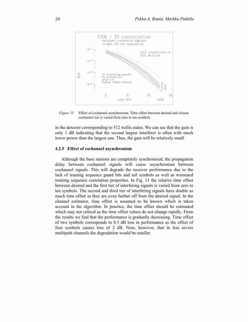
Although the base stations are completely synchronised, the propagationdelay between cochannel signals will cause asynchronism betweencochannel signals. This will degrade the receiver performance due to thelack of training sequence guard bits and tail symbols as well as worsenedtraining sequence correlation properties. In Fig. 13 the relative time offsetbetween desired and the first tier of interfering signals is varied from zero toten symbols. The second and third tier of interfering signals have double asmuch time offset as they are even further off from the desired signal. In thechannel estimator, time offset is assumed to be known which is takenaccount in the algorithm. In practice, the time offset should be estimatedwhich may not critical as the time offset values do not change rapidly. Fromthe results we find that the performance is gradually decreasing. Time offsetof two symbols corresponds to 0.3 dB loss in performance as the offset offour symbols causes loss of 2 dB. Note, however, that in less severemultipath channels the degradation would be smaller.
Figure 13 Effect of cochannel asynchronism. Time offset between desired and closestcochannel tier is varied from zero to ten symbols.
#. Radio aspects 25
5. SYSTEM REQUIREMENTS
5.1 Base station synchronisation
As indicated in Sec. 3.3, to support the proposed channel estimationmethod base station synchronisation is required enabling training sequencesfrom different cochannels being received overlapping in time. The amountof tolerated asynchronism will depend on the training sequence design aswell as maximum multipath delay. Synchronous systems also guarantee thatthe interference source is not different at the both ends of the burst whichwould make the interference suppression even more difficult.
There are several options how the base station synchronisation can beachieved. GPS (Global Positioning System) is a well known solution foroutdoor cells and is also used by the IS-95 standard. The price of GPSreceivers is nowadays reasonable but GPS has an disadvantage of notproviding very good indoor coverage. GPS offers very accuratesynchronisation, which on the other hand is not necessarily required by thisapplication. Another method is to obtain base station synchronisation is tomonitor the neighbour cell beacon signal, i.e. the BCCH carriersynchronisation sequence. If the cell sizes are small, the propagation delaycauses only a small error in synchronisation accuracy and synchronisationcan be obtained directly. For larger cell sizes and to obtain bettersynchronisation accuracy the propagation delay can be eliminated if 1. the distance between base stations is known or 2. base stations measure the time offsets between their own and the
neighbour base station synchronisation sequences and report the resultsto a common node, e.g., to a Base Station Controller (BSC) or MobileSwitching Centre (MSC). The common node can compute the requiredtime correction in the BSs’ reference clocks.
5.2 Cell sizes and reuse factors
Although the base stations are synchronised, the cochannel signalsexperience different propagation delays which will cause asynchronism. Torestrict the maximum propagation delay the reuse factors and cell sizes arelimited. This is not a major problem since interference suppression is mostlyneeded in high capacity urban areas which inherently apply rather small cellsizes due to the requirement of high capacity and rather steep signalattenuation. Also usage of frequency hopping and DI cancellationthemselves manifests a lower reuse in the network.
26 Pekka A. Ranta, Markku Pukkila
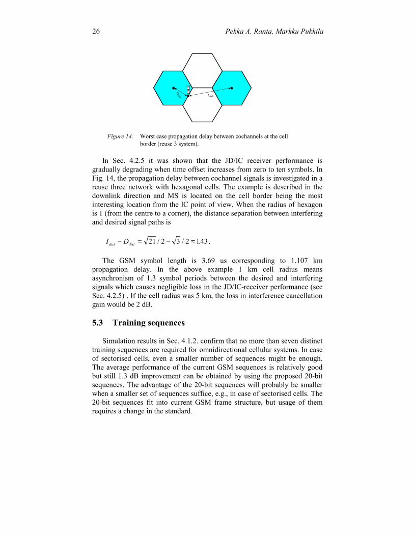
In Sec. 4.2.5 it was shown that the JD/IC receiver performance isgradually degrading when time offset increases from zero to ten symbols. InFig. 14, the propagation delay between cochannel signals is investigated in areuse three network with hexagonal cells. The example is described in thedownlink direction and MS is located on the cell border being the mostinteresting location from the IC point of view. When the radius of hexagonis 1 (from the centre to a corner), the distance separation between interferingand desired signal paths is
I Ddist dist− = − ≈21 2 3 2 143/ / . .
The GSM symbol length is 3.69 us corresponding to 1.107 kmpropagation delay. In the above example 1 km cell radius meansasynchronism of 1.3 symbol periods between the desired and interferingsignals which causes negligible loss in the JD/IC-receiver performance (seeSec. 4.2.5) . If the cell radius was 5 km, the loss in interference cancellationgain would be 2 dB.
5.3 Training sequences
Simulation results in Sec. 4.1.2. confirm that no more than seven distincttraining sequences are required for omnidirectional cellular systems. In caseof sectorised cells, even a smaller number of sequences might be enough.The average performance of the current GSM sequences is relatively goodbut still 1.3 dB improvement can be obtained by using the proposed 20-bitsequences. The advantage of the 20-bit sequences will probably be smallerwhen a smaller set of sequences suffice, e.g., in case of sectorised cells. The20-bit sequences fit into current GSM frame structure, but usage of themrequires a change in the standard.
IdistD
dist
Figure 14. Worst case propagation delay between cochannels at the cellborder (reuse 3 system).
#. Radio aspects 27
The allocation of different training sequences can be done manually onthe cell basis but it can be made automatically according to themeasurements done in base stations. It is possible even consider automaticchange of training sequences on the call basis or even during a call.
5.4 Control channels
If the performance of traffic channels can be improved with CCI, it isnecessary to be able improve the performance of control channelsaccordingly. This is not a problem in those GSM control channels using thesame training sequences as the traffic channels, e.g., SACCH, FACCH etc.,since they can gain from JD/IC in a manner similar TCH channels. On thecontrary, RACH and FCCH and SCH do not use the GSM trainingsequences and may require algorithm redesign in the receivers or in theworst case algorithm redesign of the standard. One way to avoid the problemis to guarantee lower interference level for BCCH and RACH timeslots bynetwork planning which can be accomplished rather easily thanks to the BSssynchronisation.
6. APPLICATIONS
From the capacity point of view, due to the lack of antenna diversityreception in the downlink, it is clear that JD/IC technique should be usedespecially in the mobile receivers. When considering the application JD/ICtechnique in a current GSM network, it is evident that most of the mobileswill not be able to support JD/IC technique. Thus the reuse need to beadjusted according to performance of conventional receivers. Anyhow, thereare at least five ways to gain from interference cancellation:1. provide lower transmission powers for JD/IC mobiles and thereby
generate less interference for the others.2. enlarge the cell sizes of JD/IC mobiles3. allocated dedicated carriers or timeslots for JD/IC mobiles and do
separate frequency planning for them with a lower reuse4. give enhanced quality or a higher bit rate for mobiles supporting JD/IC
technique.If new networks are designed supporting only JD/IC mobiles right from
the beginning, an advantage of JD/IC technique is that the frequencyplanning will be less critical as JD/IC can reduce the interference problem.In microcells, JD/IC technique can be used to solve the street crossinginterference problem [Ran97a] and potentially to alleviate the problem ofstreet corner quality drop. In any case, the provision of BS synchronisation

28 Pekka A. Ranta, Markku Pukkila
is much easier in small cells such as indoor and microcell systems. Aninteresting alternative is to comply SDMA systems with the JD/IC receivertechnique.
7. CONCLUSIONS
In this Section an overview of CCI cancellation by joint detection inGSM systems has been presented. It has been shown that CCI cancellation isfeasible in the GSM system to enhance the performance of the future GSMnetworks. The presented network simulations confirm that in the GSMnetwork there is a high probability of a dominant interfering signal whichgives significant computational advantage with only a minor loss inperformance.
The receiver performance is analysed with a novel simulation systemincluding 18 interferers each representing an interferer from a hexagonalomnicell layout. The results show that GSM training sequences performsatisfactorily although performance can be improved by 1.3 dB using analternative training sequence set. The training sequence set size of sevensequences seem to be enough in the omnicell system, and the set size mightbe further decreased in case of sectorised cells. If a smaller set size is used,the penalty of using current GSM sequences becomes smaller. The effect ofbase station activity was investigated with respect to receiver performance.Depending on the BS activity factor the relative IC-gain varies between 4and 9 dB at BER 10e-2. It was also demonstrated that JD of the twostrongest interfering signals gives only 1 dB improvement compared to DIcancellation alone.
In addition to new receiver algorithms, the main requirement which theJD/IC technique poses to the system is the base station synchronisationenabling joint channel estimation. In addition, some limitations are set alsofor cell sizes and reuse factors due to the asynchronism caused by thepropagation delay between cochannel signals. Moreover, either manual orautomatic allocation of distinct training sequences for the nearestcochannels is necessary. As a conclusion, the GSM standard as suchsupports rather well the application of JD/IC technique, but some changesmaybe favoured e.g. in the training sequence or control channel side.
REFERENCES
[Abe70] K. Abend and B.D. Fritchman, “Statistical Detection for CommunicationChannels with Intersymbol Interference”, Proc. of IEEE, Vol. 58, No. 5,pp.779-785, May 1970.
#. Radio aspects 29
[Ant97] C. Antón-Haro, J.A.R. Fonollosa and J.R. Fonollosa, “Blind ChannelEstimation and Data Detection Using Hidden Markov Models”, IEEETrans. on Signal Proc., Vol. 45, No. 1, January, 1997, pp. 241-246.
[Bea95] N. C. Beaulieu et. al, “Estimating the Distribution of a Sum ofIndependent Lognormal Random Variables”, IEEE Trans. on Comm.,Vol. 43, No. 12, December, 1995, pp.2869-2873.
[Ber96] R. Berangi, P. Leung, and M. Faulkner, “Cochannel interferencecancellation for mobile communications systems”, Proc. IEEEInternational Conference on Universal Personal Communications(ICUPC), Sep. 29th- Oct. 2nd , Boston, 1995, pp. 443-447.
[Bot95] G. Bottomley, K. Jamal, “Adaptive arrays and MLSE equalisation” 45thIEEE Vehicular Technology Conference , Chigaco, 1995.
[Cha66] R.W. Chang and J.C. Hancock, “On Receiver Structures for ChannelsHaving Memory”, IEEE Trans. on Inf. Theory, Vol. 12, No. 3, pp. 463-468, Oct. 1996.
[Che92] S. Chen and B. Mulgrew, "Overcoming co-channel interference using anadaptive radial basis function equaliser", Signal Processing, Vol. 28,1992, Elsevier Science Publishers B.V., pp.91-107.
[Clar78] A.P. Clark, J.D. Harvey and J.P. Driscoll, “Near- maximum likelihooddetection processes for distorted signals”, The Radio and ElectronicEngineer, Vol. 48. No. 6. pp. 301-309, June 1978.
[Due88] Alexandra Duel-Hallen and Chris Hegaard, “Delayed Decision-FeedbackSequence Estimation”, IEEE Transactions on Communications, Vol. 37,No. 5, pp.428-436, May 1989.
[Edw96] N. Edwardsson, “Studies of Joint Detection-MLSE in the GSM System”,Master’s Thesis, Royal Institute of Technology, IR-SB-EX-9607,Stockholm, Jan. 1996.
[Esc97] Marko Escartin and Pekka A. Ranta, “Interference Rejection with a SmallAntenna Array at the Mobile Scattering Environment”, proceedings ofFirst IEEE Signal Processing Workshop on Signal Processing Advancesin Wireless Communications (SPAWC), La Bastille, Paris, April 16-18th.
[ETSa] ETSI STC-SMG11, “AMR - Working assumptions”, Draft 0.0.4.,Meeting #2, Sophia Antipolis, April 21-25, 1997.
[ETSb] ETSI TC-SMG, “Overall description of the GPRS radio interface; Stage2”, GSM Recommendations 03.64, v.5.0.0, July 1997.
[ETSc] ETSI TC-SMG, GSM Recommendations, Series 5, March 1997.[Ett76] W. van Etten, "Maximum-Likelihood Receiver for Multiple Channel
Transmission Systems", IEEE Trans. on Comm., February 1976, pp. 276-283.
[Eyu86]. M. Vedat Eyuboglu amd Shadid U.H. Dureshi, “Reduced-State SequenceEstimation with Set partitioning and Decision Feedback”, IEEETransactions on Communications, Vol. 36, No. 1, pp.13-20, Jan. 1988.
[Fal93] D. D. Falconer, M. Abdulrahman, W. K. Lo, B. R. Petersen and A. U. H.Sheikh, "Advances in Equalization and Diversity fpr Portable WirelessSystems", Digital Signal Processing, No. 3, pp. 148-162, 1993.
[For72] G. David Forney Jr., "Maximum-Likelihood Sequence Estimation ofDigital Sequences in the Presence of Intersymbol Interference", IEEETrans. on Inf. Theory, Vol. IT-18, No. 3, pp. 363-378, May 1972.
30 Pekka A. Ranta, Markku Pukkila
[Gir93] K. Giridhar et. al., "Joint Estimation Algorithms for Co-channel SignalDemodulation", in Proc. IEEE Int. Conf. on Commun. (ICC), Geneva,1993, pp. 1497-1501.
[How93] I. Howitt, "Recent Developments in Applying Neural Nets to Equalizationand Interference Rejection", Virginia Tech’s 3rd Symposium on WirelessPersonal Communications, Blacksburg, June 9-11, 1993.
[Karl96] J. Karlsson, J. Heinegård, "Interference rejection combining for GSM", inproc. of 5th IEEE International Conference Universal PersonalCommunications, Boston, MA, Sept. 29- Oct. 2, pp.433-437.
[Lau86] Piere A. Laurent, “Exact and Approximate Construction of Digital PhaseModulations by Superposition of Amplitude Modulated Pulses (AMP),IEEE Transactions on Communications, Vol. 34, No. 2, pp.150-160, Feb.1986.
[Li95] Y. Li, B. Vucetic, and Y. Sato, “Optimum Soft-Output Detection forChannels with Intersymbol Interference”, IEEE Trans. on Inf. Theory,Vol. IT-41, No. 3, pp. 704-713, May 1995.
[Mos96] Shimon Moshavi, “Multi-user Detection for DS-CDMACommunications”, IEEE Communications Magazine, Vol. 34, No. 10,Oct. 1996, pp. 124-136.
[Mou92] Michel Mouly, Marie-B. Pautet, “The GSM System for MobileCommunications”, 1992.
[Mou94] C. Mourot, J. De Vile, R. Hopper, P. Ranta, "The ATDMA equaliserdesign and implementation", in proceedings of RACE MobileTelecommunications Workshop, Amsterdam, May 17-19,1994.
[Puk97] Markku Pukkila and Pekka A. Ranta, “Channel Estimator for MultipleCo-channel Demodulation in TDMA Mobile Systems”, 2nd EuropeanMobile Communications Conference (EMPCC'97), Bonn, Sept 30 -Oct 2,1997.
[Ran95a] P.A. Ranta, A Hottinen, Z.C. Honkasalo, “Co-channel interferencecancelling receiver for TDMA mobile systems”, in proceedings of IEEEInternational Conference on Communications (ICC’95), Seattle, 1995,pp.17-21.
[Ran95b] P.A. Ranta, Z.Honkasalo and J.Tapaninen, “TDMA Cellular NetworkApplication of an Interference Cancellation Technique”, in proceedings of1995 IEEE Vehicular Technology Conference (VTC’95), July 25-28Chicago, Illinois, USA, pp.296-300.
[Ran96] P.A. Ranta, A. Lappeteläinen, Z.C. Honkasalo, “Interference cancellationby Joint Detection in Random Frequency Hopping TDMA networks”, inproceedings of IEEE International Conference on Universal Personalcommunications (ICUPC’96), Sept. 29- Oct. 2, 1996, Cambridge, MA.
[Ran97a] Pekka A. Ranta and Antti Lappeteläinen, “Application of dominantinterference cancellation in street microcells”, IEEE InternationalConference on Communications (ICC’97), Montreal, 8-12th June, 1997,pp.17-21.
[Ran97b] Pekka A. Ranta, Markku Pukkila, “Recent results of Co-channelInterference Suppression by Joint Detection in GSM”, to be published in6th International Conference on Advances in Communications andControl, Corfu, Greece, 23-27 June 1997.
[Ran97c] Pekka A. Ranta and Marko Escartin, “Dominant interferencecancellation by adaptive antennas in GSM”, in proceedings of IEEE
#. Radio aspects 31
International Conference on Personal, Indoor, Mobile RadioCommunications, Helsinki, Sept. 1-4, 1997.
[Rob95] P. Robertson, E. Villebrun, and P. Hoeher, “A Comparison of Optimaland Sub-Optimal MAP Decoding Algorithms Operating in the LogDomain”, in proceedings of Internatiol Conference on Communications(ICC’95), Seattle, WA, June 18-22, 1995, pp. 1009-1013.
[Ste94] B. Steiner and P. Jung, "Optimum and Suboptimum Channel Estimationfor the Uplink CDMA Mobile Radio Systems with Joint Detection",European Transactions on Telecommunications, Vol. 5, No. 1, Jan.-Feb.,1994, pp. 39-50.
[Stu96] Gordon Stüber, “Principles of mobile communications”, KluwerAcademic Publishers, p. 665, 1996.
[Ung74] Gottfried Ungerboeck, "Adaptive Maximum Likelihood Receiver forCarrier Modulated Data-Transmission Systems", IEEE Trans. onCommun., Vol. COM-22, No. 5, pp. 624-636, May 1974.
[Wal95] S. W. Wales, "Technique for cochannel interference suppression inTDMA mobile systems", IEE Proc. Commun., Vol. 142, No.2, April,1995, pp.106-114.
[Win84] J. Winters, “Optimum Combining in Digital Mobile Radio withCochannel Interference”, IEEE Journal on Selected Areas inCommunications, Vol. SAC-2, No. 4, pp. 528-539, July 1984.
[Yos94] H. Yoshino, K. Fukawa, H. Suzuki, "Interference Cancelling Equalizer(ICE) for Mobile Communications", Proc. IEEE Int. Conf. on Commun.(ICC), New Orleans, 1994, pp. 1427-1432.