nih spill prevention, control and countermeasure plan bethesda spcc... · the purpose of this spill...
TRANSCRIPT
Spill Prevention, Control and Countermeasure Plan
National Institutes of Health Bethesda Campus
9000 Rockville Pike
Bethesda, MD 20892
13 September 2017
Prepared by
EnDyna
7926 Jones Branch Drive, Suite 620; McLean, VA 22102
and
Tellevate, LLC One West Court Square, Suite 750; Decatur, GA 30303

BLANK PAGE
NATIONAL INSTITUTES OF HEALTH
Spill Prevention, Control and Countermeasure Plan | 13 September 2017
i
TABLE OF CONTENTS
INTRODUCTION ..................................................................................................................................................... iii
PART 1: Plan Administration .................................................................................................................. 1-1
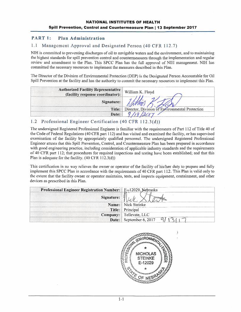
1.1 Management Approval and Designated Person (40 CFR 112.7) .............................................................. 1-1 1.2 Professional Engineer Certification (40 CFR 112.3(d)) ............................................................................. 1-1 1.3 Location of SPCC Plan (40 CFR 112.3(e)) ............................................................................................... 1-2 1.4 Plan Review (40 CFR 112.3 and 112.5) ................................................................................................... 1-2
1.4.1 Changes in Facility Configuration ............................................................................................... 1-2 1.4.2 Scheduled Plan Reviews ............................................................................................................ 1-2 1.4.3 Record of Plan Reviews ............................................................................................................. 1-2
1.5 Facilities, Procedures, Methods of Equipment Not Yet Fully Operational (40 CFR 112.7) ....................... 1-3 1.6 Cross Reference with SPCC Provisions (40 CFR 112.7) ......................................................................... 1-3
PART 2: General Facility Information .................................................................................................... 2-1
2.1 Facility Description (40 CFR 112.7(a)(3)) ................................................................................................. 2-1 2.1.1 Location and Activities ................................................................................................................ 2-1 2.1.2 Oil Storage.................................................................................................................................. 2-1
2.2 Evaluation of Discharge Potential ............................................................................................................. 2-4 2.2.1 Distance to Navigable Waters and Adjoining Shorelines and Flow Paths .................................. 2-4 2.2.2 Discharge History ....................................................................................................................... 2-4
PART 3: Discharge Prevention – General SPCC Provisions ............................................................... 3-1
3.1 Compliance with Applicable Requirements (40 CFR 112.7(a)(2)) ............................................................ 3-1 3.2 Facility Layout Diagram (40 CFR 112.7(a)(3)) .......................................................................................... 3-1 3.3 Spill Reporting (40 CFR 112.7(a)(4)) ........................................................................................................ 3-1 3.4 Potential Discharge Volumes and Direction of Flow (40 CFR 112.7(b)) ................................................... 3-1 3.5 Containment and Diversionary Structures (40 CFR 112.7(c)) .................................................................. 3-3 3.6 Practicability of Secondary Containment (40 CFR 112.7(d)) .................................................................... 3-4 3.7 Inspections, Tests and Records (40 CFR 112.7(e)).................................................................................. 3-4
3.7.1 Daily Inspection .......................................................................................................................... 3-5 3.7.2 Monthly Inspection ...................................................................................................................... 3-5 3.7.3 Annual Inspection ....................................................................................................................... 3-5 3.7.4 Periodic Integrity Testing ............................................................................................................ 3-6
3.8 Personnel, Training and Discharge Prevention Procedures (40 CFR 112.7(f)) ........................................ 3-6 3.9 Security (40 CFR 112.7(g)) ....................................................................................................................... 3-6 3.10 Tank Truck Loading/Unloading Requirements (40 CFR 112.7(c)) ............................................................ 3-7
3.10.1 Secondary Containment ............................................................................................................. 3-7 3.10.2 Loading/Unloading Procedures .................................................................................................. 3-7
3.11 Brittle Fracture Evaluation (40 CFR 112.7(i)) ............................................................................................ 3-8 3.12 Conformance with State and Local Applicable Requirements (40 CFR 112.7(j)) ..................................... 3-8
PART 4: Discharge Prevention – SPCC Provisions for Onshore Facilities (Excluding Production Facilities) ................................................................................................................................... 4-1
4.1 Facility Drainage (40 CFR 112.8(b)) ......................................................................................................... 4-1 4.2 Bulk Storage Containers (40 CFR 112.8(c)) ............................................................................................. 4-1
4.2.1 Construction (40 CFR 112.8(c)(1)) ............................................................................................. 4-9 4.2.2 Secondary Containment (40 CFR 112.8(c)(2)) ........................................................................... 4-9 4.2.3 Drainage of Diked Areas (40 CFR 112.8(c)(3)) ........................................................................ 4-10
NATIONAL INSTITUTES OF HEALTH
Spill Prevention, Control and Countermeasure Plan | 13 September 2017
ii
4.2.4 Corrosion Protection (40 CFR 112.8(c)(4)) ............................................................................... 4-11 4.2.5 Partially Buried and Bunkered Storage Tanks (40 CFR 112.8(c)(5)) ........................................ 4-11 4.2.6 Inspections and Tests (40 CFR 112.8(c)(6)) ............................................................................ 4-11 4.2.7 Heating Coils (40 CFR 112.8(c)(7)) .......................................................................................... 4-11 4.2.8 Overfill Prevention Systems (40 CFR 112.8(c)(8)) ................................................................... 4-11 4.2.9 Effluent Treatment Facilities (40 CFR 112.8(c)(9)) ................................................................... 4-11 4.2.10 Visible Discharges (40 CFR 112.8(c)(10)) ................................................................................ 4-11 4.2.11 Mobile and Portable Containers (40 CFR 112.8(c)(11)) ........................................................... 4-12 4.2.12 Oil-Filled Equipment ................................................................................................................. 4-14
4.3 Transfer Operations, Pumping and In-Plant Processes (40 CFR 112.8(d)) ............................................ 4-18
PART 5: Discharge Response ................................................................................................................ 5-1
5.1 Response to a Minor Discharge ................................................................................................................ 5-1 5.2 Response to a Major Discharge ................................................................................................................ 5-2 5.3 Waste Disposal ......................................................................................................................................... 5-3 5.4 Discharge Notification ............................................................................................................................... 5-3 5.5 Cleanup Contractors and Equipment Suppliers ........................................................................................ 5-4
PART 6: APPENDICES ............................................................................................................................ 6-1
APPENDIX A: Site Plan/Facility Diagrams .......................................................................................................... 6-3 APPENDIX B: Substantial Harm Determination .................................................................................................. 6-9 APPENDIX C: Facility Inspection Checklists ..................................................................................................... 6-11 APPENDIX D: Record of Containment Dike Drainage ...................................................................................... 6-15 APPENDIX E: Record of Annual Discharge Prevention Briefings and Training ................................................ 6-17 APPENDIX F: Emergency Contacts .................................................................................................................. 6-19 APPENDIX G: Discharge Notification Form ...................................................................................................... 6-21 APPENDIX H: Discharge Response Equipment Inventory ................................................................................ 6-23 APPENDIX I: Agency Notification Standard Report .......................................................................................... 6-37 APPENDIX J: Compliance Plan ........................................................................................................................ 6-39 APPENDIX K: Incident Reporting Form ............................................................................................................. 6-41

NATIONAL INSTITUTES OF HEALTH
Spill Prevention, Control and Countermeasure Plan | 13 September 2017
iii
INTRODUCTION
The purpose of this Spill Prevention, Control, and Countermeasure (SPCC) Plan is to describe measures
implemented by the National Institutes of Health (NIH) to prevent oil discharges from occurring, and to prepare
NIH to respond in a safe, effective, and timely manner to mitigate the impacts of a discharge.
This Plan has been prepared to meet the requirements of Title 40, Code of Federal Regulations, Part 112 (40
CFR part 112), and supersedes the earlier Plan developed to meet provisions in effect since 1974.
In addition to fulfilling requirements of 40 CFR part 112, this SPCC Plan is used as a reference for oil storage
information and testing records, as a tool to communicate practices on preventing and responding to discharges
with employees, as a guide to facility inspections, and as a resource during emergency response.
NIH management has determined that the NIH Bethesda Campus does not pose a risk of substantial harm under
40 CFR part 112, as recorded in the “Substantial Harm Determination” included in Appendix B of this Plan.
Therefore, a Facility Response Plan (FRP) is not required for inclusion into this Plan.
This Plan provides guidance on key actions that NIH must perform to comply with the SPCC rule:
Complete monthly and annual site inspections as outlined in the Inspection, Tests, and Records section of
this Plan (Section 3.7) using the inspection checklists included in Appendix C.
Perform preventive maintenance of equipment, secondary containment systems, and discharge prevention
systems described in this Plan as needed to keep them in proper operating conditions.
Conduct annual employee training as outlined in the Personnel, Training, and Spill Prevention Procedures
section of this Plan (Section 3.8) and utilize the log in Appendix E to document the training.
If either of the following occurs, submit the SPCC Plan to the U.S. Environmental Protection Agency (EPA)
Region 3 and the Maryland Department of Environment (MDE), along with other information as detailed
in Section 5.4 of this Plan:
o The facility discharges more than 1,000 gallons of oil into or upon the navigable waters of the U.S. or
adjoining shorelines in a single spill event; or
o The facility discharges oil in quantity greater than 42 gallons in each of two spill events within any 12-
month period.
Amend the SPCC Plan within six (6) months whenever there is a change in facility design, construction,
operation, or maintenance that materially affects the facility’s spill potential. The revised Plan must be
recertified by a PE.
Review the Plan on an annual basis. Update the Plan to reflect any “administrative changes” that are
applicable, such as personnel changes or revisions to contact information, such as phone numbers.
Administrative changes must be documented in the Plan review log of Section 1.4 of this Plan, but do not
have to be certified by a PE.
Review the SPCC Plan at least once every five years and amend it to include more effective prevention and
control technology, if such technology will significantly reduce the likelihood of a spill event and has been
proven effective in the field at the time of the review. Plan amendments, other than administrative changes
discussed above, must be recertified by a Professional Engineer (PE) on the certification page in Section
1.2 of this Plan.

NATIONAL INSTITUTES OF HEALTH
Spill Prevention, Control and Countermeasure Plan | 13 September 2017
iv
BLANK PAGE
NATIONAL INSTITUTES OF HEALTH
Spill Prevention, Control and Countermeasure Plan | 13 September 2017
1-2
1.3 Location of SPCC Plan (40 CFR 112.3(e))
In accordance with 40 CFR 112.3(e), complete copies of this SPCC Plan are maintained in the Division of
Environmental Protection (DEP) in Room 2S11 in Building 13, Division of Facilities, Operations and
Maintenance (DFOM) in Room 1416 in Building 13, Division of Technical Resources (DTR) in the first floor
office in the Central Utility Plant and Division of Fire and Rescue Services in Building 51. The DEP Offices
are attended from 7:00 AM to 5:00 PM Monday through Friday.
1.4 Plan Review (40 CFR 112.3 and 112.5)
1.4.1 Changes in Facil i ty Configuration
In accordance with 40 CFR 112.5(a), NIH periodically reviews and evaluates this SPCC Plan for any change
in the facility design, construction, operation, or maintenance that materially affects the facility’s potential for
an oil discharge, including, but not limited to:
Commissioning or decommissioning of containers;
Reconstruction, replacement, or installation of piping systems;
Construction or demolition that might alter secondary containment structures; or
Changes of product or service, revisions to standard operation, modification of testing/inspection
procedures, and use of new or modified industry standards or maintenance procedures.
Amendments to the Plan made to address changes of this nature are referred to as technical amendments, and
must be certified by a PE. Non-technical amendments can be done (and must be documented in this section) by
the facility owner and/or operator. Non-technical amendments include the following:
Change in the name or contact information (i.e., telephone numbers) of individuals responsible for the
implementation of this Plan; or
Change in the name or contact information of spill response or cleanup contractors.
NIH will make the needed revisions to the SPCC Plan as soon as possible, but no later than six months after the
change occurs. The Plan must be implemented as soon as possible following any technical amendment, but no
later than six months from the date of the amendment. The DEP Director is responsible for initiating and
coordinating revisions to the SPCC Plan.
1.4.2 Scheduled Plan Reviews
In accordance with 40 CFR 112.5(b), NIH reviews this SPCC Plan at least once every five years. Revisions to
the Plan, if needed, are made within six months of the five-year review. A registered PE certifies any technical
amendment to the Plan, as described above, in accordance with 40 CFR 112.3(d). This Plan is dated September
6, 2017. The next plan review is therefore scheduled to take place on or prior to September 13, 2022.
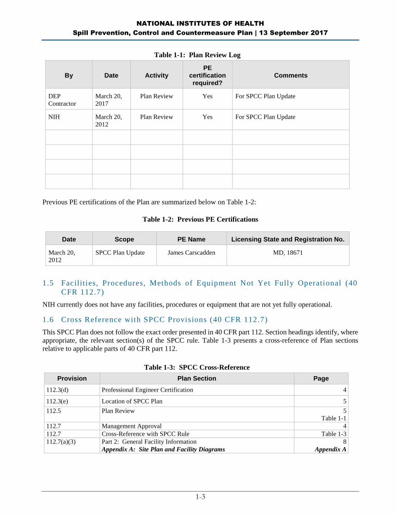
1.4.3 Record of Plan Reviews
Scheduled five-year reviews and Plan amendments are recorded in the Plan Review Log (Table 1-1). This log
will be completed even if no amendment is made to the Plan as a result of the review. Unless a technical or
administrative change prompts an earlier review of the Plan, the next scheduled review of this Plan will occur
by September 13, 2022.
NATIONAL INSTITUTES OF HEALTH
Spill Prevention, Control and Countermeasure Plan | 13 September 2017
1-3
Table 1-1: Plan Review Log
By Date Activity PE
certification required?
Comments
DEP
Contractor
March 20,
2017
Plan Review Yes For SPCC Plan Update
NIH March 20,
2012
Plan Review Yes For SPCC Plan Update
Previous PE certifications of the Plan are summarized below on Table 1-2:
Table 1-2: Previous PE Certifications
Date Scope PE Name Licensing State and Registration No.
March 20,
2012
SPCC Plan Update James Carscadden MD, 18671
1.5 Facilities, Procedures, Methods of Equipment Not Yet Fully Operational (40
CFR 112.7)
NIH currently does not have any facilities, procedures or equipment that are not yet fully operational.
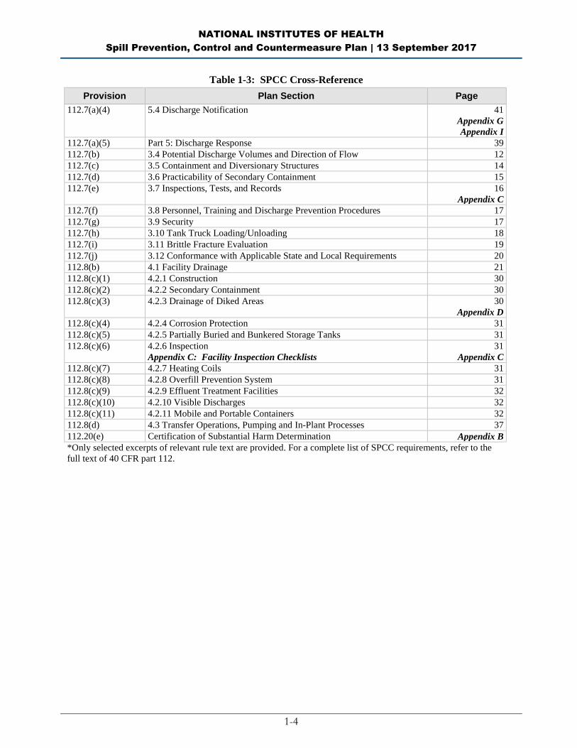
1.6 Cross Reference with SPCC Provisions (40 CFR 112.7)
This SPCC Plan does not follow the exact order presented in 40 CFR part 112. Section headings identify, where
appropriate, the relevant section(s) of the SPCC rule. Table 1-3 presents a cross-reference of Plan sections
relative to applicable parts of 40 CFR part 112.
Table 1-3: SPCC Cross-Reference
Provision Plan Section Page
112.3(d) Professional Engineer Certification 4
112.3(e) Location of SPCC Plan 5
112.5 Plan Review 5
Table 1-1
112.7 Management Approval 4
112.7 Cross-Reference with SPCC Rule Table 1-3
112.7(a)(3) Part 2: General Facility Information
Appendix A: Site Plan and Facility Diagrams
8
Appendix A
NATIONAL INSTITUTES OF HEALTH
Spill Prevention, Control and Countermeasure Plan | 13 September 2017
1-4
Table 1-3: SPCC Cross-Reference
Provision Plan Section Page
112.7(a)(4) 5.4 Discharge Notification 41
Appendix G
Appendix I
112.7(a)(5) Part 5: Discharge Response 39
112.7(b) 3.4 Potential Discharge Volumes and Direction of Flow 12
112.7(c) 3.5 Containment and Diversionary Structures 14
112.7(d) 3.6 Practicability of Secondary Containment 15
112.7(e) 3.7 Inspections, Tests, and Records
16
Appendix C
112.7(f) 3.8 Personnel, Training and Discharge Prevention Procedures 17
112.7(g) 3.9 Security 17
112.7(h) 3.10 Tank Truck Loading/Unloading 18
112.7(i) 3.11 Brittle Fracture Evaluation 19
112.7(j) 3.12 Conformance with Applicable State and Local Requirements 20
112.8(b) 4.1 Facility Drainage 21
112.8(c)(1) 4.2.1 Construction 30
112.8(c)(2) 4.2.2 Secondary Containment 30
112.8(c)(3) 4.2.3 Drainage of Diked Areas 30
Appendix D
112.8(c)(4) 4.2.4 Corrosion Protection 31
112.8(c)(5) 4.2.5 Partially Buried and Bunkered Storage Tanks 31
112.8(c)(6) 4.2.6 Inspection
Appendix C: Facility Inspection Checklists
31
Appendix C
112.8(c)(7) 4.2.7 Heating Coils 31
112.8(c)(8) 4.2.8 Overfill Prevention System 31
112.8(c)(9) 4.2.9 Effluent Treatment Facilities 32
112.8(c)(10) 4.2.10 Visible Discharges 32
112.8(c)(11) 4.2.11 Mobile and Portable Containers 32
112.8(d) 4.3 Transfer Operations, Pumping and In-Plant Processes 37
112.20(e) Certification of Substantial Harm Determination Appendix B
*Only selected excerpts of relevant rule text are provided. For a complete list of SPCC requirements, refer to the
full text of 40 CFR part 112.
NATIONAL INSTITUTES OF HEALTH
Spill Prevention, Control and Countermeasure Plan | 13 September 2017
2-1
PART 2: General Facility Information
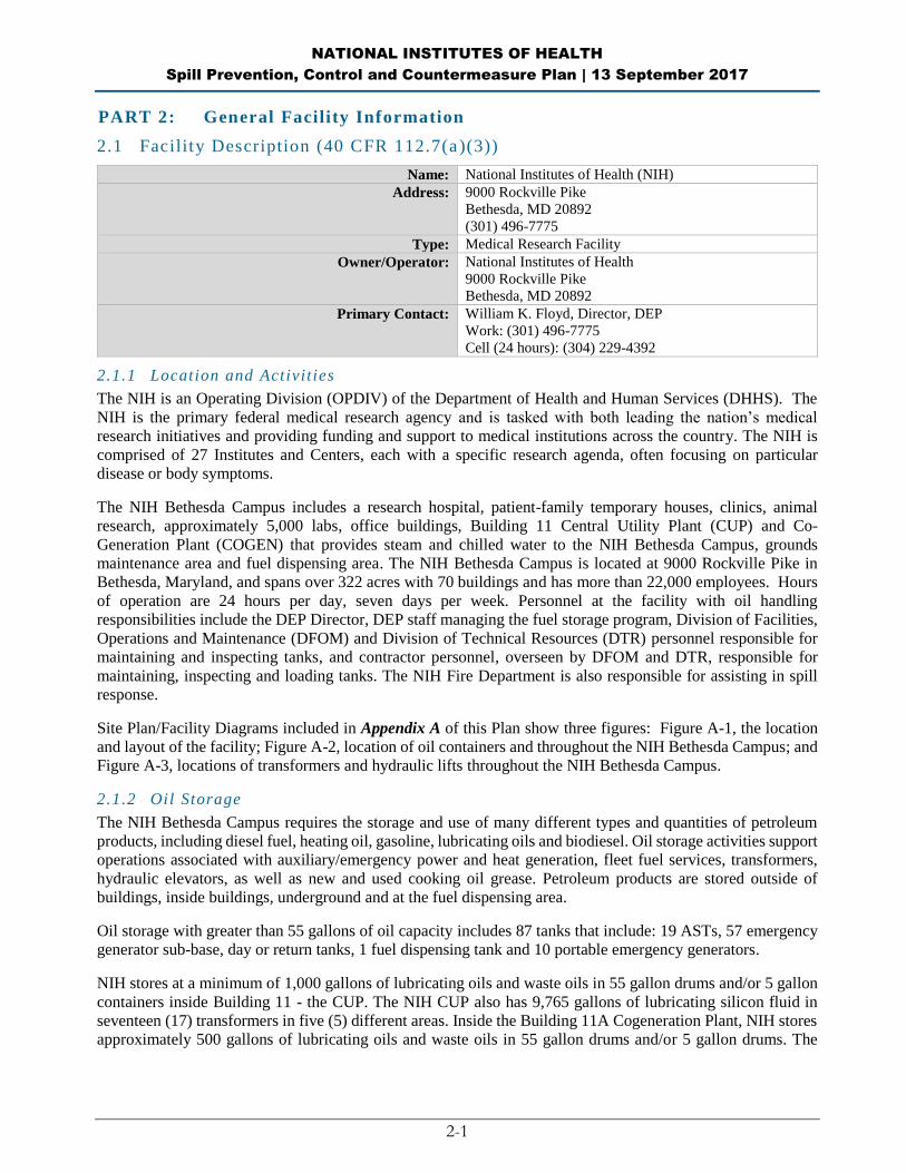
2.1 Facility Description (40 CFR 112.7(a )(3))
Name: National Institutes of Health (NIH)
Address: 9000 Rockville Pike
Bethesda, MD 20892
(301) 496-7775
Type: Medical Research Facility
Owner/Operator: National Institutes of Health
9000 Rockville Pike
Bethesda, MD 20892
Primary Contact: William K. Floyd, Director, DEP
Work: (301) 496-7775
Cell (24 hours): (304) 229-4392
2.1.1 Location and Activit ies
The NIH is an Operating Division (OPDIV) of the Department of Health and Human Services (DHHS). The
NIH is the primary federal medical research agency and is tasked with both leading the nation’s medical
research initiatives and providing funding and support to medical institutions across the country. The NIH is
comprised of 27 Institutes and Centers, each with a specific research agenda, often focusing on particular
disease or body symptoms.
The NIH Bethesda Campus includes a research hospital, patient-family temporary houses, clinics, animal
research, approximately 5,000 labs, office buildings, Building 11 Central Utility Plant (CUP) and Co-
Generation Plant (COGEN) that provides steam and chilled water to the NIH Bethesda Campus, grounds
maintenance area and fuel dispensing area. The NIH Bethesda Campus is located at 9000 Rockville Pike in
Bethesda, Maryland, and spans over 322 acres with 70 buildings and has more than 22,000 employees. Hours
of operation are 24 hours per day, seven days per week. Personnel at the facility with oil handling
responsibilities include the DEP Director, DEP staff managing the fuel storage program, Division of Facilities,
Operations and Maintenance (DFOM) and Division of Technical Resources (DTR) personnel responsible for
maintaining and inspecting tanks, and contractor personnel, overseen by DFOM and DTR, responsible for
maintaining, inspecting and loading tanks. The NIH Fire Department is also responsible for assisting in spill
response.
Site Plan/Facility Diagrams included in Appendix A of this Plan show three figures: Figure A-1, the location
and layout of the facility; Figure A-2, location of oil containers and throughout the NIH Bethesda Campus; and
Figure A-3, locations of transformers and hydraulic lifts throughout the NIH Bethesda Campus.
2.1.2 Oil Storage
The NIH Bethesda Campus requires the storage and use of many different types and quantities of petroleum
products, including diesel fuel, heating oil, gasoline, lubricating oils and biodiesel. Oil storage activities support
operations associated with auxiliary/emergency power and heat generation, fleet fuel services, transformers,
hydraulic elevators, as well as new and used cooking oil grease. Petroleum products are stored outside of
buildings, inside buildings, underground and at the fuel dispensing area.
Oil storage with greater than 55 gallons of oil capacity includes 87 tanks that include: 19 ASTs, 57 emergency
generator sub-base, day or return tanks, 1 fuel dispensing tank and 10 portable emergency generators.
NIH stores at a minimum of 1,000 gallons of lubricating oils and waste oils in 55 gallon drums and/or 5 gallon
containers inside Building 11 - the CUP. The NIH CUP also has 9,765 gallons of lubricating silicon fluid in
seventeen (17) transformers in five (5) different areas. Inside the Building 11A Cogeneration Plant, NIH stores
approximately 500 gallons of lubricating oils and waste oils in 55 gallon drums and/or 5 gallon drums. The

NATIONAL INSTITUTES OF HEALTH
Spill Prevention, Control and Countermeasure Plan | 13 September 2017
2-2
Cogeneration Plant has 850 gallons of R-Temp fluid in two (2) transformers in two (2) different areas. In
addition, NIH stores an estimated 5500 gallons in 100 55-gallon drums in other areas of the NIH Bethesda
Campus that are managed by DFOM. NIH Bethesda Campus has 117 network transformers with oil capacity
above 55 gallons and a total transformer oil capacity of 47,608 gallons. NIH Bethesda Campus also has 43
hydraulic elevator reservoirs above 55-gallons and a total oil capacity of 14,832 gallons.
There are 18 underground storage tanks (USTs) located at the site that are exempt from this SPCC Plan. The
USTs are exempt from this SPCC Plan because they are subject to, and meet, all the technical requirements of
40 CFR Part 280 and Maryland’s more stringent UST Program at COMAR 26.10.02-.11, as approved under 40
CFR part 281, State Program Approval (SPA). Thus, they are neither counted in the storage capacity for this
facility nor are subject to the requirements of 40 CFR 112 (exempt under 40 CFR 112.1(d)(4)). These USTs
include two 567,000 gallon tanks and four 10,000 gallon tank for CUP boilers and three 10,000 gallon tanks at
the fuel dispensing area.
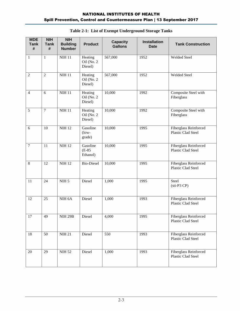
The capacities of exempt USTs present at the site are listed in Table 2-1; the locations are indicated on Figure
A-2, Appendix A. All other containers with a capacity of 55 gallons or more are included in this Plan. The
capacity for the USTs are not included in the total capacity because they are exempt as described below. There
is oil-filled equipment owned and operated by the utility, Pepco, and not part of the NIH “facility”. This oil-
filled equipment is also exempt from this SPCC Plan.
As shown in Appendix B, NIH has determined that the NIH Bethesda Campus does not have the potential to
cause substantial harm to the environment in the event of a discharge into or on navigable waters or adjoining
shorelines and thus is not required to prepare and submit a Facility Response Plan. The underground storage
capacity does not count towards the facility’s total oil storage and thus the total oil storage at NIH Bethesda
Campus does not exceed the total oil storage threshold for developing a Facility Response Plan.
Total Oil Storage: 176,994 gallons*
*NOTE: This includes all non-exempt ASTs, emergency generators, and oil drums in the Central Utility
Plant and other areas of the NIH Bethesda Campus that have storage capacity greater than 55 gallons. This
does not include the exempt USTs located at the NIH Bethesda Campus.
Note: The USTs are subject to, and meet, all the technical requirements of 40 CFR Part 280 and Maryland’s
more stringent UST Program at COMAR 26.10.02-.11, as approved under 40 CFR part 281, and are therefore
neither counted in the storage capacity for this facility nor are subject to the requirements of 40 CFR 112
(exempt under 40 CFR 112.1(d)(4)). Their locations are indicated on the Facility Diagram in Appendix A.
NATIONAL INSTITUTES OF HEALTH
Spill Prevention, Control and Countermeasure Plan | 13 September 2017
2-3
Table 2-1: List of Exempt Underground Storage Tanks
MDE Tank
#
NIH Tank
#
NIH Building Number
Product Capacity Gallons
Installation Date
Tank Construction
1 1 NIH 11 Heating
Oil (No. 2
Diesel)
567,000 1952 Welded Steel
2 2 NIH 11 Heating
Oil (No. 2
Diesel)
567,000 1952 Welded Steel
4 6 NIH 11 Heating
Oil (No. 2
Diesel)
10,000 1992 Composite Steel with
Fiberglass
5 7 NIH 11 Heating
Oil (No. 2
Diesel)
10,000 1992 Composite Steel with
Fiberglass
6 10 NIH 12 Gasoline
(low-
grade)
10,000 1995 Fiberglass Reinforced
Plastic Clad Steel
7 11 NIH 12 Gasoline
(E-85
Ethanol)
10,000 1995 Fiberglass Reinforced
Plastic Clad Steel
8 12 NIH 12 Bio-Diesel 10,000 1995 Fiberglass Reinforced
Plastic Clad Steel
11 24 NIH 5 Diesel 1,000 1995 Steel
(sti-P3 CP)
12 25 NIH 6A Diesel 1,000 1993 Fiberglass Reinforced
Plastic Clad Steel
17 49 NIH 29B Diesel 4,000 1995 Fiberglass Reinforced
Plastic Clad Steel
18 50 NIH 21 Diesel 550 1993 Fiberglass Reinforced
Plastic Clad Steel
20 29 NIH 52 Diesel 1,000 1993 Fiberglass Reinforced
Plastic Clad Steel
NATIONAL INSTITUTES OF HEALTH
Spill Prevention, Control and Countermeasure Plan | 13 September 2017
2-4
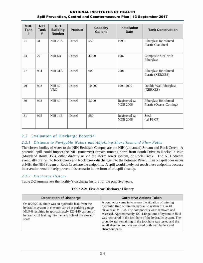
MDE Tank
#
NIH Tank
#
NIH Building Number
Product Capacity Gallons
Installation Date
Tank Construction
21 31 NIH 29A Diesel 550 1995 Fiberglass Reinforced
Plastic Clad Steel
24 27 NIH 6B Diesel 4,000 1987 Composite Steel with
Fiberglass
27 994 NIH 31A Diesel 600 2001 Fiberglass Reinforced
Plastic (XERXES)
29 993 NIH 40 -
VRC
Diesel 10,000 1999-2000 Double Wall Fiberglass
(XERXES)
30 992 NIH 49 Diesel 5,000 Registered w/
MDE 2006
Fiberglass Reinforced
Plastic (Owens-Corning)
31 995 NIH 14E Diesel 550 Registered w/
MDE 2006
Steel
(sti-P3 CP)
2.2 Evaluation of Discharge Potential
2.2.1 Distance to Navigable Waters and Adjoining Shorelines and Flow Paths
The closest bodies of water to the NIH Bethesda Campus are the NIH (unnamed) Stream and Rock Creek. A
potential spill could impact the NIH (unnamed) Stream running north from South Drive to Rockville Pike
(Maryland Route 355), either directly or via the storm sewer system, or Rock Creek. The NIH Stream
eventually drains into Rock Creek and Rock Creek discharges into the Potomac River. If an oil spill does occur
at NIH, the NIH Stream or Rock Creek are the endpoints. A spill would likely not reach these endpoints because
intervention would likely prevent this scenario in the form of oil spill cleanup.
2.2.2 Discharge History
Table 2-2 summarizes the facility’s discharge history for the past five years.
Table 2-2: Five-Year Discharge History
Description of Discharge Corrective Actions Taken
On 8/26/2016, there was an hydraulic leak from the
hydraulic system in elevator car #4 at parking garage
MLP-8 resulting in approximately 120-140 gallons of
hydraulic oil leaking into the jack hole of the elevator
shaft.
A contractor came in to assess the situation of missing
hydraulic fluid within the hydraulic system of Car #4
elevator at MLP-8. The components were removed and
assessed. Approximately 120-140 gallons of hydraulic fluid
was recovered in the jack hole of the hydraulic system. The
groundwater remaining in the jack hole was tested and the
small sheen on top was removed both with bailers and
absorbent pads.

NATIONAL INSTITUTES OF HEALTH
Spill Prevention, Control and Countermeasure Plan | 13 September 2017
2-5
Description of Discharge Corrective Actions Taken
On 6/13/2016, approximately 25 gallons of diesel
leaked onto the pavement between Bldg. 34 and the
bulk fuel tank secondary containment from a rupture in
the underbelly tank of a dump truck at the demolition
site at Bldg. 34.
Contractors and NIH Fire Department immediately put
absorbent pads and kitty litter absorbent on the diesel spill
path on the roadway from Bldg. 34 to the secondary
containment. The construction crew immediately directed
the driver to the known secondary containment area to
ensure minimal damage from the leak. All diesel was
thoroughly cleaned from the roadways and there was no
release into the environment.
On 12/23/2015, fuel oil was detected in the Bldg. 11
(CUP) Basement in the Steam Side. The fuel oil source
originated from the door post to stair well 2.
In order to rectify the issue, oil containment booms were
placed to surround the door post to stair well 2. The oil leak
appears to have ceased and it being monitored to see if any
further action is needed. No oil has reached the drain
troughs located in the basement steam side.
On 12/9/2015, a 5-gallon container of hydraulic fluid
was spilled onto the pavement at MLP-8 when the
contractor was off-loading a pallet of 5-gallon
containers of hydraulic fluid while performing
maintenance on the elevators.
Absorbent materials were delivered by Clean Ventures to
the contractor who was performing maintenance on the
hydraulic elevators. This contractor thoroughly removed
the spilled granulated material with absorbent material and
pads and cleaned the area. There was no oil released into
the environment as a result of this spill.
On 5/19/2015, the Bldg. 5 Emergency Generator Day
tank pump was found continually running because the
high level alarm for the pump was disabled.
Initially, 10 gallons was cleaned up at the scene and on
5/25/2015, the oil/water separator (OWS) downgradient
was cleaned out.
On 5/17/2015, the NIH Fire Department discovered a
diesel fuel smell in the OWS Containment system area
upon arrival.
Fire Department personnel deployed big booms and pads
from the adjacent shed at containment area. This further
decreased downstream contamination. NIH Fire
Department and DEP personnel checked upstream areas at
Bldgs. 11 and 12 to assess source and never found
anything.
On May 10, 2015, the Cogen’s gas turbine cooler failed,
which resulted in chilled water and oil to collect in the
turbine enclosure.
The turbine drains to a wastewater drain tank and then is
pumped into an oil water separator. The water is sent the
blowdown flash tank while the oil is collected in a waste oil
storage tank. The oily waste water was contained within
the Cogen drain system. Clean Harbors was called on
5/11/2015 to pump out the oily waste water, which was
contained in the Cogen drain system.
On 6/12/2012, there was a 200-300 gallon container of
kitchen grease that leaked an unknown quantity in the
Cafeteria Loading Dock approximately 100 feet towards
South Drive. When DEP arrived at the scene, there was
a stain on the pavement near the AST of kitchen grease
and tire path down the road.
Clay absorbent material was repeatedly applied and
removed throughout the day several times followed by a
wash-down of the pavement.
On 1/25/2012, there was a hydraulic oil leak from a
truck
The plug was replaced.

NATIONAL INSTITUTES OF HEALTH
Spill Prevention, Control and Countermeasure Plan | 13 September 2017
2-6
BLANK PAGE
NATIONAL INSTITUTES OF HEALTH
Spill Prevention, Control and Countermeasure Plan | 13 September 2017
3-1
PART 3: Discharge Prevention – General SPCC Provisions
The following measures are implemented to prevent oil discharges during the handling, use, or transfer of oil
products at the facility. Oil-handling employees have received annual training in the proper implementation of
these measures.
3.1 Compliance with Applicable Requirements (40 CFR 112.7(a)(2))
40 CFR 112 requires compliance with all applicable requirements, as described in this plan. All tanks and drums
located at NIH Bethesda Campus have adequate secondary containment. Inspections of tanks are conducted
and personnel are trained in spill response.
3.2 Facility Layout Diagram (40 CFR 112.7(a)(3))
Appendix A, Figure A-1, shows the general location of the facility on a U.S. Geological Survey topographic
map. Appendix A, Figure A-2, presents a layout of the facility and the location of storage tanks and 55-gallon
drums. As required under 40 CFR 112.7(a)(3), the facility diagram indicates the location and content of ASTs,
USTs, and transfer stations and connecting piping. The facility diagram also identifies the location of and mark
as “exempt” underground tanks that are exempted from the requirements of this part under §112.1(d)(4).
3.3 Spill Reporting (40 CFR 112.7(a)(4) )
The discharge notification form included in Appendix G will be completed upon immediate detection of a
discharge and prior to reporting a spill to the proper notification contacts.
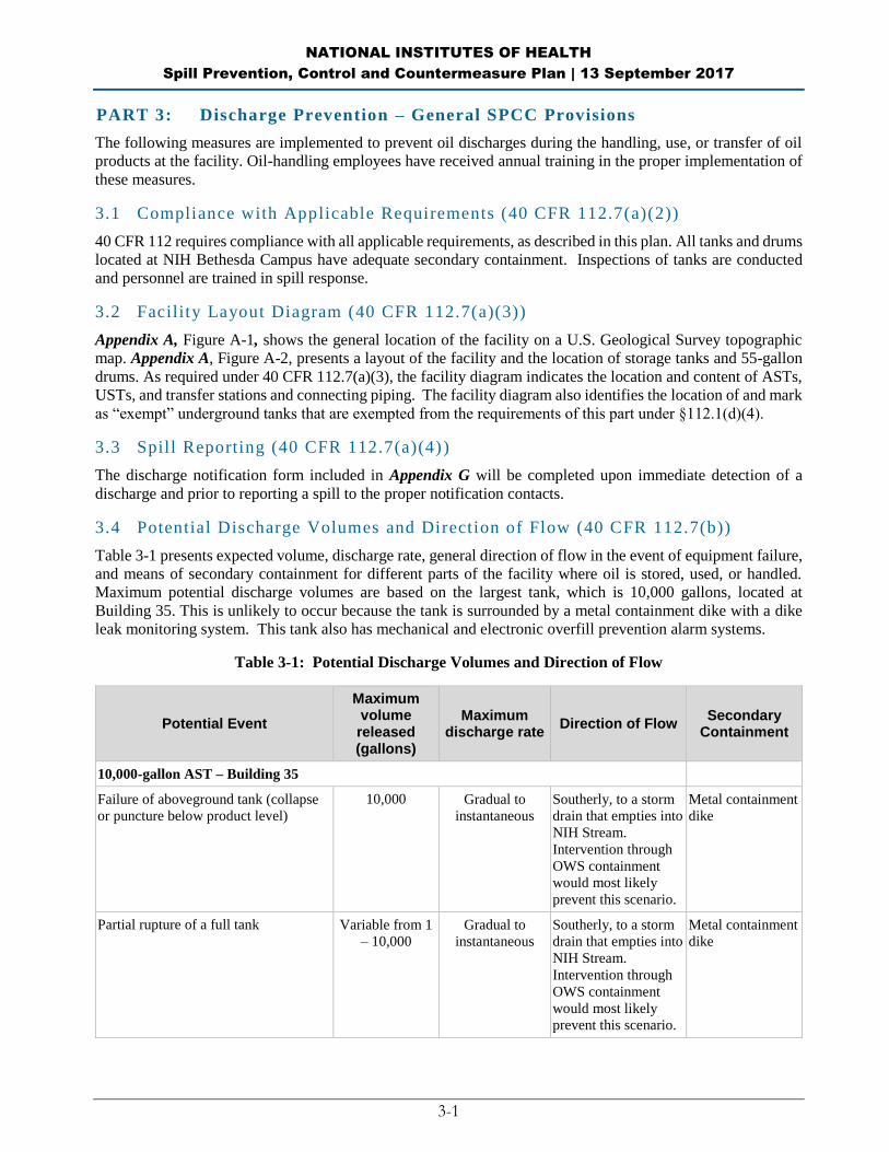
3.4 Potential Discharge Volumes and Direction of Flow (40 CFR 112.7(b))
Table 3-1 presents expected volume, discharge rate, general direction of flow in the event of equipment failure,
and means of secondary containment for different parts of the facility where oil is stored, used, or handled.
Maximum potential discharge volumes are based on the largest tank, which is 10,000 gallons, located at
Building 35. This is unlikely to occur because the tank is surrounded by a metal containment dike with a dike
leak monitoring system. This tank also has mechanical and electronic overfill prevention alarm systems.
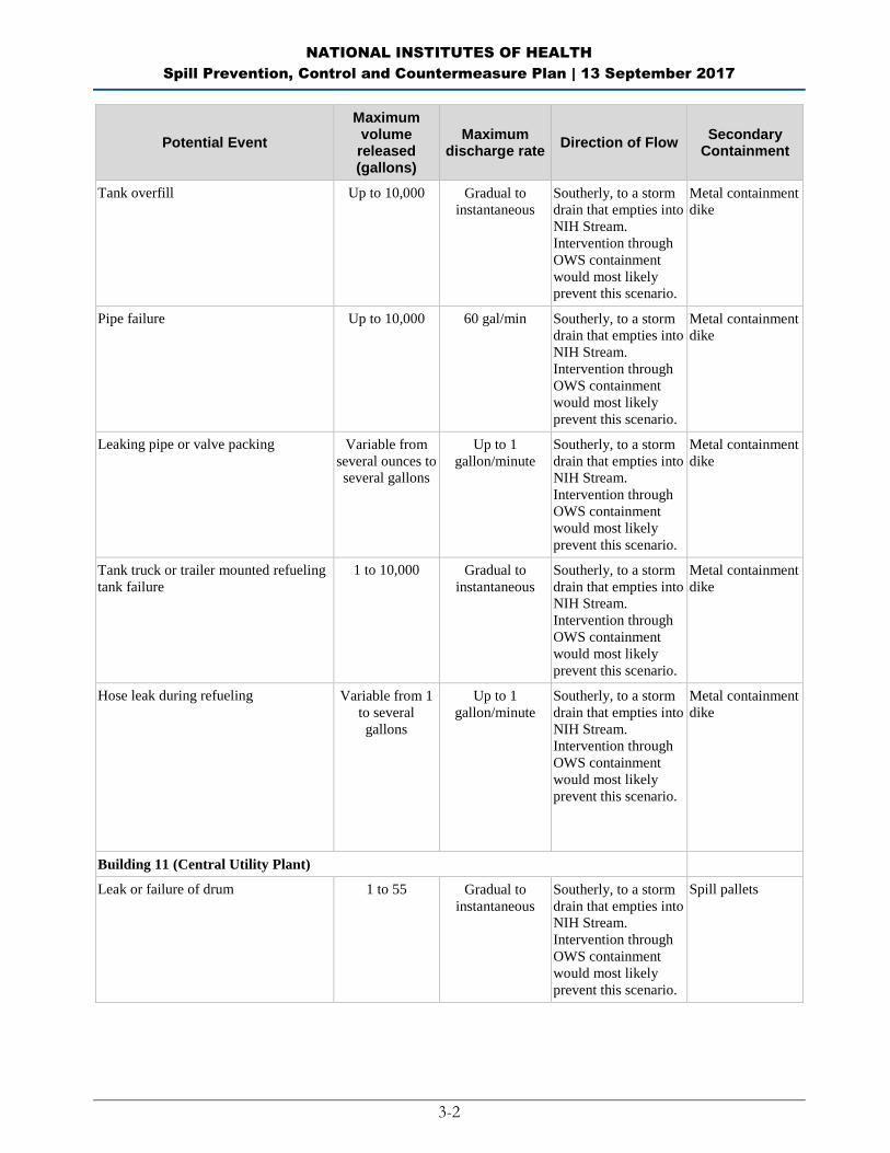
Table 3-1: Potential Discharge Volumes and Direction of Flow
Potential Event
Maximum volume released (gallons)
Maximum discharge rate
Direction of Flow Secondary
Containment
10,000-gallon AST – Building 35
Failure of aboveground tank (collapse
or puncture below product level)
10,000 Gradual to
instantaneous
Southerly, to a storm
drain that empties into
NIH Stream.
Intervention through
OWS containment
would most likely
prevent this scenario.
Metal containment
dike
Partial rupture of a full tank Variable from 1
– 10,000
Gradual to
instantaneous
Southerly, to a storm
drain that empties into
NIH Stream.
Intervention through
OWS containment
would most likely
prevent this scenario.
Metal containment
dike
NATIONAL INSTITUTES OF HEALTH
Spill Prevention, Control and Countermeasure Plan | 13 September 2017
3-2
Potential Event
Maximum volume released (gallons)
Maximum discharge rate
Direction of Flow Secondary
Containment
Tank overfill Up to 10,000 Gradual to
instantaneous
Southerly, to a storm
drain that empties into
NIH Stream.
Intervention through
OWS containment
would most likely
prevent this scenario.
Metal containment
dike
Pipe failure Up to 10,000 60 gal/min Southerly, to a storm
drain that empties into
NIH Stream.
Intervention through
OWS containment
would most likely
prevent this scenario.
Metal containment
dike
Leaking pipe or valve packing Variable from
several ounces to
several gallons
Up to 1
gallon/minute
Southerly, to a storm
drain that empties into
NIH Stream.
Intervention through
OWS containment
would most likely
prevent this scenario.
Metal containment
dike
Tank truck or trailer mounted refueling
tank failure
1 to 10,000 Gradual to
instantaneous
Southerly, to a storm
drain that empties into
NIH Stream.
Intervention through
OWS containment
would most likely
prevent this scenario.
Metal containment
dike
Hose leak during refueling Variable from 1
to several
gallons
Up to 1
gallon/minute
Southerly, to a storm
drain that empties into
NIH Stream.
Intervention through
OWS containment
would most likely
prevent this scenario.
Metal containment
dike
Building 11 (Central Utility Plant)
Leak or failure of drum 1 to 55 Gradual to
instantaneous
Southerly, to a storm
drain that empties into
NIH Stream.
Intervention through
OWS containment
would most likely
prevent this scenario.
Spill pallets
NATIONAL INSTITUTES OF HEALTH
Spill Prevention, Control and Countermeasure Plan | 13 September 2017
3-3
Potential Event
Maximum volume released (gallons)
Maximum discharge rate
Direction of Flow Secondary
Containment
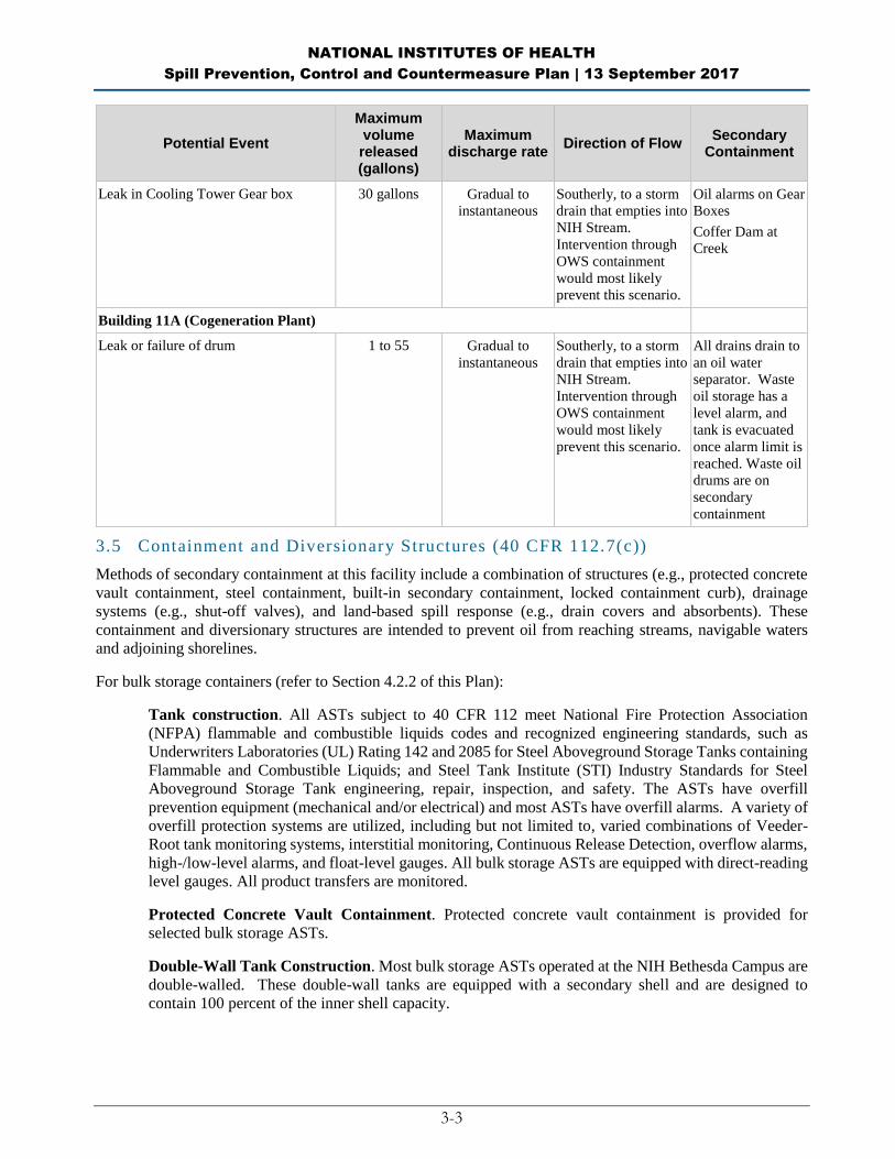
Leak in Cooling Tower Gear box 30 gallons Gradual to
instantaneous
Southerly, to a storm
drain that empties into
NIH Stream.
Intervention through
OWS containment
would most likely
prevent this scenario.
Oil alarms on Gear
Boxes
Coffer Dam at
Creek
Building 11A (Cogeneration Plant)
Leak or failure of drum 1 to 55 Gradual to
instantaneous
Southerly, to a storm
drain that empties into
NIH Stream.
Intervention through
OWS containment
would most likely
prevent this scenario.
All drains drain to
an oil water
separator. Waste
oil storage has a
level alarm, and
tank is evacuated
once alarm limit is
reached. Waste oil
drums are on
secondary
containment
3.5 Containment and Diversionary Structures (40 CFR 112.7(c))
Methods of secondary containment at this facility include a combination of structures (e.g., protected concrete
vault containment, steel containment, built-in secondary containment, locked containment curb), drainage
systems (e.g., shut-off valves), and land-based spill response (e.g., drain covers and absorbents). These
containment and diversionary structures are intended to prevent oil from reaching streams, navigable waters
and adjoining shorelines.
For bulk storage containers (refer to Section 4.2.2 of this Plan):
Tank construction. All ASTs subject to 40 CFR 112 meet National Fire Protection Association
(NFPA) flammable and combustible liquids codes and recognized engineering standards, such as
Underwriters Laboratories (UL) Rating 142 and 2085 for Steel Aboveground Storage Tanks containing
Flammable and Combustible Liquids; and Steel Tank Institute (STI) Industry Standards for Steel
Aboveground Storage Tank engineering, repair, inspection, and safety. The ASTs have overfill
prevention equipment (mechanical and/or electrical) and most ASTs have overfill alarms. A variety of
overfill protection systems are utilized, including but not limited to, varied combinations of Veeder-
Root tank monitoring systems, interstitial monitoring, Continuous Release Detection, overflow alarms,
high-/low-level alarms, and float-level gauges. All bulk storage ASTs are equipped with direct-reading
level gauges. All product transfers are monitored.
Protected Concrete Vault Containment. Protected concrete vault containment is provided for
selected bulk storage ASTs.
Double-Wall Tank Construction. Most bulk storage ASTs operated at the NIH Bethesda Campus are
double-walled. These double-wall tanks are equipped with a secondary shell and are designed to
contain 100 percent of the inner shell capacity.

NATIONAL INSTITUTES OF HEALTH
Spill Prevention, Control and Countermeasure Plan | 13 September 2017
3-4
Containment Dikes/Berms/Curbs. Most single-wall bulk storage ASTs are surrounded by metal
containment dikes with dike leak monitoring systems or containment berms. Some double-walled ASTs
are surrounded by spill containment curbs, which serves as a tertiary spill containment system.
In transfer areas and other parts of a facility where a discharge could occur:
Spill pallets. Spill pallets are used for secondary containment for the 55-gallon oil drums stored
throughout the NIH Bethesda Campus.
Spill Containers. Fill ports for all ASTs are equipped with spill buckets to contain residual fuel from
the piping/hose connections. Drip pans are drained from the bottom to a bucket for disposal or manually
returned to the tank.
Absorbent materials. Spill cleanup kits that include absorbent materials, booms, and other portable
barriers are available on NIH contractor servicing vehicles. Gloves, trash bags, absorbent materials,
buckets, a wet vacuum or a pump are available and constantly resupplied.
Temporary Berms. There are 9 portable emergency generators located on the NIH Bethesda Campus
and six of those generators have single-walled tanks. When the single-walled portable generators are
not in use and parked at their designated location, NIH has set up temporary berms for secondary
containment. When portable generators are in use throughout the NIH Bethesda Campus, temporary
berms are placed around the single-walled tanks for secondary containment.
Some single-walled ASTs do not have adequate secondary containment and secondary containment
will be provided for those tanks according to the Compliance Plan in Appendix J.
The NIH Discharge Response Equipment Inventory is listed in Appendix H of this plan. The Inventory
is checked routinely to ensure it is properly replenished.
3.6 Practicabili ty of Secondary Containment (40 CFR 112.7(d))
NIH has determined that secondary containment is practicable at the facility.
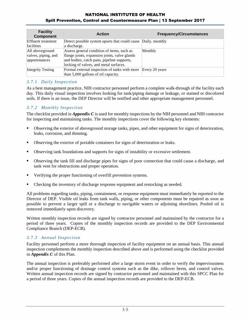
3.7 Inspections, Tests and Records (40 CFR 112.7(e))
As required by the SPCC rule, NIH performs the inspections, tests, and evaluations listed in the following table.
Table 3-2 summarizes the various types of inspections and tests performed at the facility. The inspections and
tests are described later in this section, and in the respective sections that describe different parts of the facility.
Table 3-2: Inspection and Testing Program
Facility Component
Action Frequency/Circumstances
Aboveground
container
Conduct visual inspections. Inspect outside of
container for signs of deterioration and
discharges.
Following a regular schedule (monthly, annual,
and during scheduled inspections) and whenever
material repairs are made.
Container supports
and foundation
Inspect container’s supports and foundations. Following a regular schedule (monthly, annual,
and during scheduled inspections) and whenever
material repairs are made.
Liquid level sensing
devices (overfill)
Check for proper operation. Monthly
Lowermost drain and
all outlets of tank
truck
Visually inspect. Prior to filling and departure
NATIONAL INSTITUTES OF HEALTH
Spill Prevention, Control and Countermeasure Plan | 13 September 2017
3-5
Facility Component
Action Frequency/Circumstances
Effluent treatment
facilities
Detect possible system upsets that could cause
a discharge.
Daily, monthly
All aboveground
valves, piping, and
appurtenances
Assess general condition of items, such as
flange joints, expansion joints, valve glands
and bodies, catch pans, pipeline supports,
locking of valves, and metal surfaces.
Monthly
Integrity Testing Formal external inspection of tanks with more
than 5,000 gallons of oil capacity.
Every 20 years
3.7.1 Daily Inspection
As a best management practice, NIH contractor personnel perform a complete walk-through of the facility each
day. This daily visual inspection involves looking for tank/piping damage or leakage, or stained or discolored
soils. If there is an issue, the DEP Director will be notified and other appropriate management personnel.
3.7.2 Monthly Inspection
The checklist provided in Appendix C is used for monthly inspections by the NIH personnel and NIH contractor
for inspecting and maintaining tanks. The monthly inspections cover the following key elements:
Observing the exterior of aboveground storage tanks, pipes, and other equipment for signs of deterioration,
leaks, corrosion, and thinning.
Observing the exterior of portable containers for signs of deterioration or leaks.
Observing tank foundations and supports for signs of instability or excessive settlement.
Observing the tank fill and discharge pipes for signs of poor connection that could cause a discharge, and
tank vent for obstructions and proper operation.
Verifying the proper functioning of overfill prevention systems.
Checking the inventory of discharge response equipment and restocking as needed.
All problems regarding tanks, piping, containment, or response equipment must immediately be reported to the
Director of DEP. Visible oil leaks from tank walls, piping, or other components must be repaired as soon as
possible to prevent a larger spill or a discharge to navigable waters or adjoining shorelines. Pooled oil is
removed immediately upon discovery.
Written monthly inspection records are signed by contractor personnel and maintained by the contractor for a
period of three years. Copies of the monthly inspection records are provided to the DEP Environmental
Compliance Branch (DEP-ECB).
3.7.3 Annual Inspection
Facility personnel perform a more thorough inspection of facility equipment on an annual basis. This annual
inspection complements the monthly inspection described above and is performed using the checklist provided
in Appendix C of this Plan.
The annual inspection is preferably performed after a large storm event in order to verify the imperviousness
and/or proper functioning of drainage control systems such as the dike, rollover berm, and control valves.
Written annual inspection records are signed by contractor personnel and maintained with this SPCC Plan for
a period of three years. Copies of the annual inspection records are provided to the DEP-ECB.
NATIONAL INSTITUTES OF HEALTH
Spill Prevention, Control and Countermeasure Plan | 13 September 2017
3-6
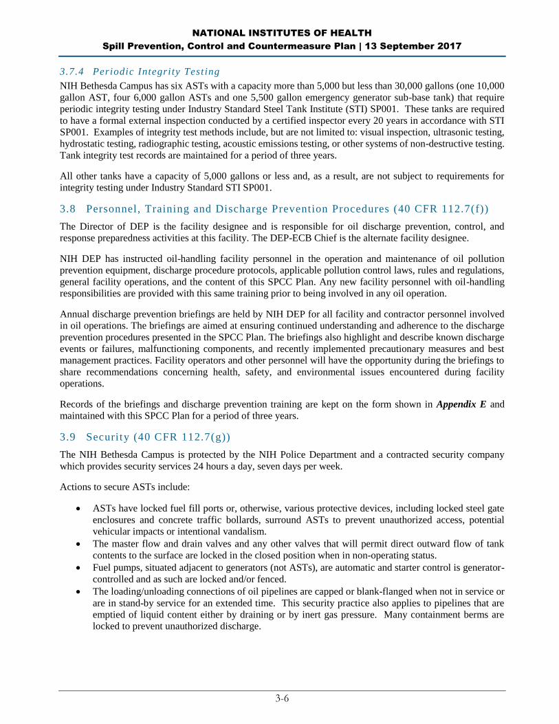
3.7.4 Periodic Integrity Test ing
NIH Bethesda Campus has six ASTs with a capacity more than 5,000 but less than 30,000 gallons (one 10,000
gallon AST, four 6,000 gallon ASTs and one 5,500 gallon emergency generator sub-base tank) that require
periodic integrity testing under Industry Standard Steel Tank Institute (STI) SP001. These tanks are required
to have a formal external inspection conducted by a certified inspector every 20 years in accordance with STI
SP001. Examples of integrity test methods include, but are not limited to: visual inspection, ultrasonic testing,
hydrostatic testing, radiographic testing, acoustic emissions testing, or other systems of non-destructive testing.
Tank integrity test records are maintained for a period of three years.
All other tanks have a capacity of 5,000 gallons or less and, as a result, are not subject to requirements for
integrity testing under Industry Standard STI SP001.
3.8 Personnel, Training and Discharge Prevention Procedures (40 CFR 112.7(f))
The Director of DEP is the facility designee and is responsible for oil discharge prevention, control, and
response preparedness activities at this facility. The DEP-ECB Chief is the alternate facility designee.
NIH DEP has instructed oil-handling facility personnel in the operation and maintenance of oil pollution
prevention equipment, discharge procedure protocols, applicable pollution control laws, rules and regulations,
general facility operations, and the content of this SPCC Plan. Any new facility personnel with oil-handling
responsibilities are provided with this same training prior to being involved in any oil operation.
Annual discharge prevention briefings are held by NIH DEP for all facility and contractor personnel involved
in oil operations. The briefings are aimed at ensuring continued understanding and adherence to the discharge
prevention procedures presented in the SPCC Plan. The briefings also highlight and describe known discharge
events or failures, malfunctioning components, and recently implemented precautionary measures and best
management practices. Facility operators and other personnel will have the opportunity during the briefings to
share recommendations concerning health, safety, and environmental issues encountered during facility
operations.
Records of the briefings and discharge prevention training are kept on the form shown in Appendix E and
maintained with this SPCC Plan for a period of three years.
3.9 Security (40 CFR 112.7(g))
The NIH Bethesda Campus is protected by the NIH Police Department and a contracted security company
which provides security services 24 hours a day, seven days per week.
Actions to secure ASTs include:
ASTs have locked fuel fill ports or, otherwise, various protective devices, including locked steel gate
enclosures and concrete traffic bollards, surround ASTs to prevent unauthorized access, potential
vehicular impacts or intentional vandalism.
The master flow and drain valves and any other valves that will permit direct outward flow of tank
contents to the surface are locked in the closed position when in non-operating status.
Fuel pumps, situated adjacent to generators (not ASTs), are automatic and starter control is generator-
controlled and as such are locked and/or fenced.
The loading/unloading connections of oil pipelines are capped or blank-flanged when not in service or
are in stand-by service for an extended time. This security practice also applies to pipelines that are
emptied of liquid content either by draining or by inert gas pressure. Many containment berms are
locked to prevent unauthorized discharge.
NATIONAL INSTITUTES OF HEALTH
Spill Prevention, Control and Countermeasure Plan | 13 September 2017
3-7
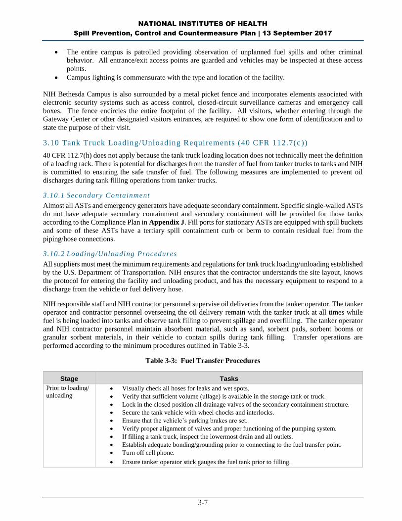
The entire campus is patrolled providing observation of unplanned fuel spills and other criminal
behavior. All entrance/exit access points are guarded and vehicles may be inspected at these access
points.
Campus lighting is commensurate with the type and location of the facility.
NIH Bethesda Campus is also surrounded by a metal picket fence and incorporates elements associated with
electronic security systems such as access control, closed-circuit surveillance cameras and emergency call
boxes. The fence encircles the entire footprint of the facility. All visitors, whether entering through the
Gateway Center or other designated visitors entrances, are required to show one form of identification and to
state the purpose of their visit.
3.10 Tank Truck Loading/Unloading Requirements (40 CFR 112.7(c ))
40 CFR 112.7(h) does not apply because the tank truck loading location does not technically meet the definition
of a loading rack. There is potential for discharges from the transfer of fuel from tanker trucks to tanks and NIH
is committed to ensuring the safe transfer of fuel. The following measures are implemented to prevent oil
discharges during tank filling operations from tanker trucks.
3.10.1 Secondary Containment
Almost all ASTs and emergency generators have adequate secondary containment. Specific single-walled ASTs
do not have adequate secondary containment and secondary containment will be provided for those tanks
according to the Compliance Plan in Appendix J. Fill ports for stationary ASTs are equipped with spill buckets
and some of these ASTs have a tertiary spill containment curb or berm to contain residual fuel from the
piping/hose connections.
3.10.2 Loading/Unloading Procedures
All suppliers must meet the minimum requirements and regulations for tank truck loading/unloading established
by the U.S. Department of Transportation. NIH ensures that the contractor understands the site layout, knows
the protocol for entering the facility and unloading product, and has the necessary equipment to respond to a
discharge from the vehicle or fuel delivery hose.
NIH responsible staff and NIH contractor personnel supervise oil deliveries from the tanker operator. The tanker
operator and contractor personnel overseeing the oil delivery remain with the tanker truck at all times while
fuel is being loaded into tanks and observe tank filling to prevent spillage and overfilling. The tanker operator
and NIH contractor personnel maintain absorbent material, such as sand, sorbent pads, sorbent booms or
granular sorbent materials, in their vehicle to contain spills during tank filling. Transfer operations are
performed according to the minimum procedures outlined in Table 3-3.
Table 3-3: Fuel Transfer Procedures
Stage Tasks
Prior to loading/
unloading Visually check all hoses for leaks and wet spots.
Verify that sufficient volume (ullage) is available in the storage tank or truck.
Lock in the closed position all drainage valves of the secondary containment structure.
Secure the tank vehicle with wheel chocks and interlocks.
Ensure that the vehicle’s parking brakes are set.
Verify proper alignment of valves and proper functioning of the pumping system.
If filling a tank truck, inspect the lowermost drain and all outlets.
Establish adequate bonding/grounding prior to connecting to the fuel transfer point.
Turn off cell phone.
Ensure tanker operator stick gauges the fuel tank prior to filling.

NATIONAL INSTITUTES OF HEALTH
Spill Prevention, Control and Countermeasure Plan | 13 September 2017
3-8
Stage Tasks
During loading/
unloading
Driver must stay with the vehicle at all times during loading/unloading activities.
Periodically inspect all systems, hoses and connections.
When loading, keep internal and external valves on the receiving tank open along with
the pressure relief valves.
When making a connection, shut off the vehicle engine. When transferring Class 3
materials, shut off the vehicle engine unless it is used to operate a pump.
Maintain communication with the pumping and receiving stations.
Monitor the liquid level in the tanker and receiving tank to prevent overflow.
Monitor flow meters to determine rate of flow.
When topping off the tank, reduce flow rate to prevent overflow.
After loading/
unloading Make sure the transfer operation is completed.
Close all tank and loading valves before disconnecting.
Securely close all vehicle internal, external, and dome cover valves before disconnecting.
Secure all hatches and fill caps (lock).
Disconnect grounding/bonding wires.
Make sure the hoses are drained to remove the remaining oil before moving them away
from the connection. Use a drip pan.
Cap the end of the hose and other connecting devices before moving them to prevent
uncontrolled leakage.
Remove wheel chocks and interlocks.
Inspect the lowermost drain and all outlets on tank truck prior to departure. If necessary,
tighten, adjust, or replace caps, valves, or other equipment to prevent oil leaking while in
transit.
3.11 Brittle Fracture Evaluation (40 CFR 112.7(i))
40 CFR 112.7(i) states that if a field-constructed aboveground container undergoes a repair, alteration,
reconstruction, or a change in service that might affect the risk of a discharge or failure due to brittle fracture
or other catastrophe, or has discharged oil or failed due to brittle fracture failure or other catastrophe, we must
evaluate the container for risk of discharge or failure due to brittle fracture or other catastrophe, and as
necessary, take appropriate action.
No tanks at NIH Bethesda Campus fall into the criteria of the above requirement because all ASTs and
emergency generators are shop-built.
3.12 Conformance with State and Local Applicable Requirements (40 CFR 112.7(j))
All ASTs are permitted by the facility’s Oil Operations Permit issued by MDE Oil Control Program. The Oil
Operations Permit requires NIH to do the following:
Measure and record in writing the liquid levels of oil storage systems prior to filling;
Manage the drainage of the emergency containment areas;
Provide MDE annually with an updated listing of ASTs;
Submit a “Plan for Notification, Containment and Clean-Up of Oil Spills” to MDE;
Immediately report any oil discharges to MDE; and
Submit a written report on removal and cleanup of spilled oil within 10 days after completion of the
control, containment, removal and restoration operations.
NATIONAL INSTITUTES OF HEALTH
Spill Prevention, Control and Countermeasure Plan | 13 September 2017
3-9
All USTs at NIH are registered with MDE and they meet the requirements of Maryland’s more stringent UST
regulations. USTs are exempt from this SPCC Plan under 40 CFR 112.1(d)(4) because Maryland’s UST
program has SPA under 40 CFR 281.
Per COMAR 26.10.01.03, Maryland has more stringent spill response requirements. The SPCC Plan
Designated Person or designee will remain on site after an oil discharge until granted permission to depart by a
representative of either MDE or any non-NIH Maryland emergency fire or rescue service or any non-NIH state,
county or local police officer on the scene. If the oil spill is less than 250 gallons, the aforementioned authorities
may grant permission to depart the spill site without notifying and receiving approval from the Maryland Waste
Management Administration. However, these requirements do not apply to this SPCC Plan because NIH will
always be the first responders for any spill on the NIH Bethesda Campus.
Per COMAR 26.10.01.05, MDE can also require further remedial action after a spill if it is determined that
there is a threat to public health and welfare or the environment; the discharge recurs as free phase oil product;
a letter issued was obtained through fraud or misinterpretation; or a new or previously undiscovered discharge
of oil is found that would require corrective action.
NATIONAL INSTITUTES OF HEALTH
Spill Prevention, Control and Countermeasure Plan | 13 September 2017
3-10
BLANK PAGE
NATIONAL INSTITUTES OF HEALTH
Spill Prevention, Control and Countermeasure Plan | 13 September 2017
4-1
PART 4: Discharge Prevention – SPCC Provisions for Onshore Facilities
(Excluding Production Facilities)
4.1 Facility Drainage (40 CFR 112.8(b))
Any potential discharge from ASTs will be restrained by secondary containment structures. NIH utilizes a
variety of discharge and pollutant prevention measures to prevent oil discharge from AST areas to storm drains
or sewer manholes. These onsite source measures include the use of concrete-vaulted and steel-contained
double-walled tanks, spill curbing, automatic tank gauge, leak detection monitoring and spill/overfill protection
systems, typically Veeder-Root automatic tank gauge and leak detection monitoring systems with
audible/visible alarm capabilities; or Pneumercator monitoring system with high/low level visible/audible
alarm.
NIH also employs various discharge prevention measures at drainage areas including Stormcepter oil/water
separators and Vortechnic oil/sediment separators, an underground surface water management structure, frog
ponding, absorbent booms, direct discharge via outfall, OWS containment or combination thereof.
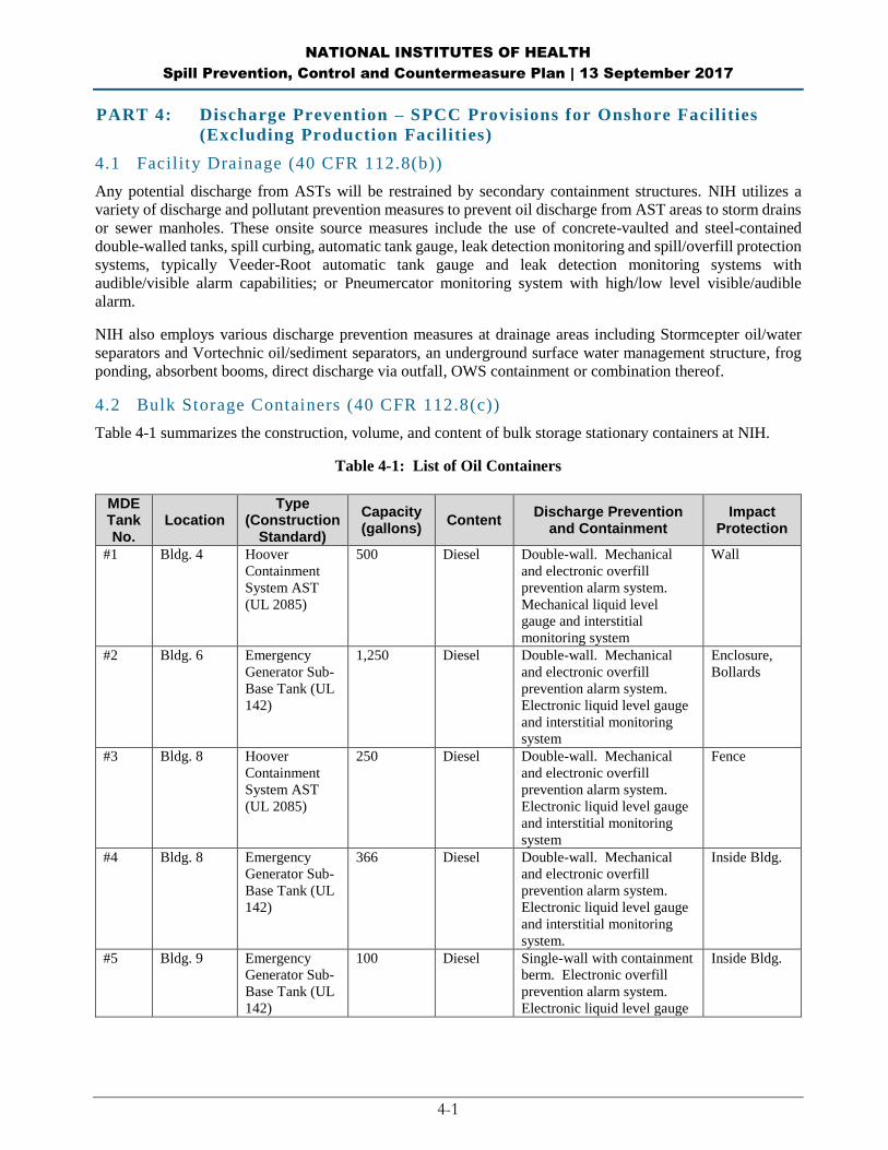
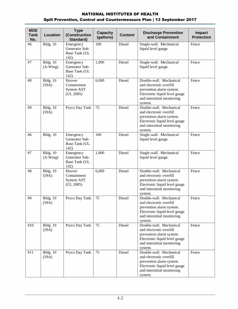
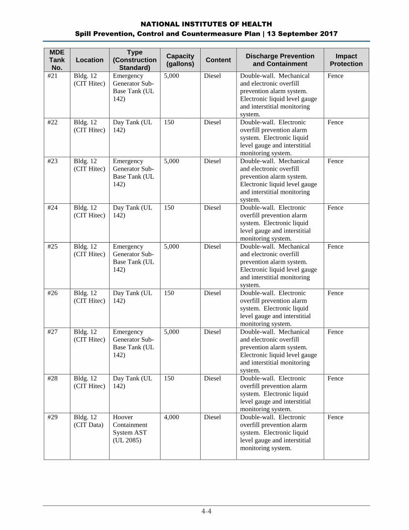
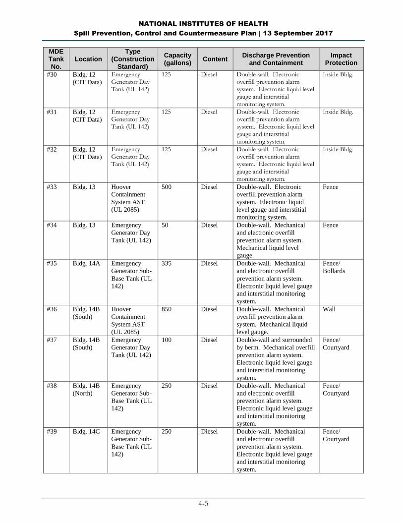
4.2 Bulk Storage Containers (40 CFR 112.8(c))
Table 4-1 summarizes the construction, volume, and content of bulk storage stationary containers at NIH.
Table 4-1: List of Oil Containers
MDE Tank No.
Location Type
(Construction Standard)
Capacity (gallons)
Content Discharge Prevention
and Containment Impact
Protection
#1 Bldg. 4 Hoover
Containment
System AST
(UL 2085)
500 Diesel Double-wall. Mechanical
and electronic overfill
prevention alarm system.
Mechanical liquid level
gauge and interstitial
monitoring system
Wall
#2 Bldg. 6 Emergency
Generator Sub-
Base Tank (UL
142)
1,250 Diesel Double-wall. Mechanical
and electronic overfill
prevention alarm system.
Electronic liquid level gauge
and interstitial monitoring
system
Enclosure,
Bollards
#3 Bldg. 8 Hoover
Containment
System AST
(UL 2085)
250 Diesel Double-wall. Mechanical
and electronic overfill
prevention alarm system.
Electronic liquid level gauge
and interstitial monitoring
system
Fence
#4 Bldg. 8 Emergency
Generator Sub-
Base Tank (UL
142)
366 Diesel Double-wall. Mechanical
and electronic overfill
prevention alarm system.
Electronic liquid level gauge
and interstitial monitoring
system.
Inside Bldg.
#5 Bldg. 9 Emergency
Generator Sub-
Base Tank (UL
142)
100 Diesel Single-wall with containment
berm. Electronic overfill
prevention alarm system.
Electronic liquid level gauge
Inside Bldg.
NATIONAL INSTITUTES OF HEALTH
Spill Prevention, Control and Countermeasure Plan | 13 September 2017
4-2
MDE Tank No.
Location Type
(Construction Standard)
Capacity (gallons)
Content Discharge Prevention
and Containment Impact
Protection
#6 Bldg. 10 Emergency
Generator Sub-
Base Tank (UL
142)
100 Diesel Single-wall. Mechanical
liquid level gauge.
Fence
#7 Bldg. 10
(A-Wing)
Emergency
Generator Sub-
Base Tank (UL
142)
1,000 Diesel Single-wall. Mechanical
liquid level gauge.
Fence
#8 Bldg. 10
(59A)
Hoover
Containment
System AST
(UL 2085)
6,000 Diesel Double-wall. Mechanical
and electronic overfill
prevention alarm system.
Electronic liquid level gauge
and interstitial monitoring
system.
Fence
#9 Bldg. 10
(59A)
Pryco Day Tank 75 Diesel Double-wall. Mechanical
and electronic overfill
prevention alarm system.
Electronic liquid level gauge
and interstitial monitoring
system.
Fence
#10 Bldg. 10
(59A)
Pryco Day Tank 75 Diesel Double-wall. Mechanical
and electronic overfill
prevention alarm system.
Electronic liquid level gauge
and interstitial monitoring
system.
Fence
#11 Bldg. 10
(59A)
Pryco Day Tank 75 Diesel Double-wall. Mechanical
and electronic overfill
prevention alarm system.
Electronic liquid level gauge
and interstitial monitoring
system.
Fence

NATIONAL INSTITUTES OF HEALTH
Spill Prevention, Control and Countermeasure Plan | 13 September 2017
4-3
MDE Tank No.
Location Type
(Construction Standard)
Capacity (gallons)
Content Discharge Prevention
and Containment Impact
Protection
#12 Bldg. 10A Hoover
Containment
System AST
(UL 2085)
1,000 Diesel Double-wall. Mechanical
and electronic overfill
prevention alarm system.
Electronic liquid level gauge
and interstitial monitoring
system.
Fence
#13 Bldg. 10A
(B1-19
Generator
Room)
Pryco Day Tank
(UL 142)
50 Diesel Single-wall. Mechanical
liquid level gauge.
Inside Bldg.
#14 Bldg. 10A
(B1-19
Generator
Room)
Pryco Return
Tank (UL 142)
50 Diesel Single-wall. Inside Bldg.
#15 Bldg. 10B
(ACRF)
Ultra Cube (UL
142)
1,500 Diesel Double-wall. Mechanical
and electronic overfill
prevention alarm system.
Mechanical liquid level
gauge and interstitial
monitoring system.
None
#16 Bldg. 10B
(ACRF)
Hoover
Containment
System AST
(UL 2085)
4,000 Diesel Double-wall. Mechanical
and electronic overfill
prevention alarm system.
Electronic liquid level gauge
and interstitial monitoring
system.
Vault
#17 Bldg. 10B
(ACRF P2
Garage)
Day Tank (UL
142)
240 Diesel Double-wall with metal dike
containment structure.
Electronic overfill prevention
equipment. Electronic liquid
level gauge and interstitial
monitoring system.
Inside Bldg.
#18 Bldg. 10B
(ICU) (P3
Garage)
Hoover
Containment
System AST
(UL 2085)
1,500 Diesel Double-wall. Mechanical
and electronic overfill
prevention equipment.
Electronic liquid level gauge
and interstitial monitoring
system.
Inside Bldg.
#19 Building 10
Data
Emergency
Generator Sub-
Base Tank (UL
142)
2,650 Diesel Double-wall. Mechanical
and electronic overfill
prevention alarm system.
Electronic liquid level gauge
and interstitial monitoring
system.
Fence
#20 Bldg. 11
(CUP)
Simplex STS
Series System
AST (UL 142)
275 Diesel Double-wall. Mechanical
and electronic overfill
prevention alarm system.
Electronic liquid level gauge
and interstitial monitoring
system.
Fence
NATIONAL INSTITUTES OF HEALTH
Spill Prevention, Control and Countermeasure Plan | 13 September 2017
4-4
MDE Tank No.
Location Type
(Construction Standard)
Capacity (gallons)
Content Discharge Prevention
and Containment Impact
Protection
#21 Bldg. 12
(CIT Hitec)
Emergency
Generator Sub-
Base Tank (UL
142)
5,000 Diesel Double-wall. Mechanical
and electronic overfill
prevention alarm system.
Electronic liquid level gauge
and interstitial monitoring
system.
Fence
#22 Bldg. 12
(CIT Hitec)
Day Tank (UL
142)
150 Diesel Double-wall. Electronic
overfill prevention alarm
system. Electronic liquid
level gauge and interstitial
monitoring system.
Fence
#23 Bldg. 12
(CIT Hitec)
Emergency
Generator Sub-
Base Tank (UL
142)
5,000 Diesel Double-wall. Mechanical
and electronic overfill
prevention alarm system.
Electronic liquid level gauge
and interstitial monitoring
system.
Fence
#24 Bldg. 12
(CIT Hitec)
Day Tank (UL
142)
150 Diesel Double-wall. Electronic
overfill prevention alarm
system. Electronic liquid
level gauge and interstitial
monitoring system.
Fence
#25 Bldg. 12
(CIT Hitec)
Emergency
Generator Sub-
Base Tank (UL
142)
5,000 Diesel Double-wall. Mechanical
and electronic overfill
prevention alarm system.
Electronic liquid level gauge
and interstitial monitoring
system.
Fence
#26 Bldg. 12
(CIT Hitec)
Day Tank (UL
142)
150 Diesel Double-wall. Electronic
overfill prevention alarm
system. Electronic liquid
level gauge and interstitial
monitoring system.
Fence
#27 Bldg. 12
(CIT Hitec)
Emergency
Generator Sub-
Base Tank (UL
142)
5,000 Diesel Double-wall. Mechanical
and electronic overfill
prevention alarm system.
Electronic liquid level gauge
and interstitial monitoring
system.
Fence
#28 Bldg. 12
(CIT Hitec)
Day Tank (UL
142)
150 Diesel Double-wall. Electronic
overfill prevention alarm
system. Electronic liquid
level gauge and interstitial
monitoring system.
Fence
#29 Bldg. 12
(CIT Data)
Hoover
Containment
System AST
(UL 2085)
4,000 Diesel Double-wall. Electronic
overfill prevention alarm
system. Electronic liquid
level gauge and interstitial
monitoring system.
Fence
NATIONAL INSTITUTES OF HEALTH
Spill Prevention, Control and Countermeasure Plan | 13 September 2017
4-5
MDE Tank No.
Location Type
(Construction Standard)
Capacity (gallons)
Content Discharge Prevention
and Containment Impact
Protection
#30 Bldg. 12
(CIT Data)
Emergency Generator Day Tank (UL 142)
125 Diesel Double-wall. Electronic overfill prevention alarm system. Electronic liquid level gauge and interstitial monitoring system.
Inside Bldg.
#31 Bldg. 12
(CIT Data)
Emergency Generator Day Tank (UL 142)
125 Diesel Double-wall. Electronic overfill prevention alarm system. Electronic liquid level gauge and interstitial monitoring system.
Inside Bldg.
#32 Bldg. 12
(CIT Data)
Emergency Generator Day Tank (UL 142)
125 Diesel Double-wall. Electronic overfill prevention alarm system. Electronic liquid level gauge and interstitial monitoring system.
Inside Bldg.
#33 Bldg. 13 Hoover
Containment
System AST
(UL 2085)
500 Diesel Double-wall. Electronic
overfill prevention alarm
system. Electronic liquid
level gauge and interstitial
monitoring system.
Fence
#34 Bldg. 13 Emergency
Generator Day
Tank (UL 142)
50 Diesel Double-wall. Mechanical
and electronic overfill
prevention alarm system.
Mechanical liquid level
gauge.
Fence
#35 Bldg. 14A Emergency
Generator Sub-
Base Tank (UL
142)
335 Diesel Double-wall. Mechanical
and electronic overfill
prevention alarm system.
Electronic liquid level gauge
and interstitial monitoring
system.
Fence/
Bollards
#36 Bldg. 14B
(South)
Hoover
Containment
System AST
(UL 2085)
850 Diesel Double-wall. Mechanical
overfill prevention alarm
system. Mechanical liquid
level gauge.
Wall
#37 Bldg. 14B
(South)
Emergency
Generator Day
Tank (UL 142)
100 Diesel Double-wall and surrounded
by berm. Mechanical overfill
prevention alarm system.
Electronic liquid level gauge
and interstitial monitoring
system.
Fence/
Courtyard
#38 Bldg. 14B
(North)
Emergency
Generator Sub-
Base Tank (UL
142)
250 Diesel Double-wall. Mechanical
and electronic overfill
prevention alarm system.
Electronic liquid level gauge
and interstitial monitoring
system.
Fence/
Courtyard
#39 Bldg. 14C Emergency
Generator Sub-
Base Tank (UL
142)
250 Diesel Double-wall. Mechanical
and electronic overfill
prevention alarm system.
Electronic liquid level gauge
and interstitial monitoring
system.
Fence/
Courtyard

NATIONAL INSTITUTES OF HEALTH
Spill Prevention, Control and Countermeasure Plan | 13 September 2017
4-6
MDE Tank No.
Location Type
(Construction Standard)
Capacity (gallons)
Content Discharge Prevention
and Containment Impact
Protection
#41 Bldg. 14E Emergency
Generator Day
Tank (UL 142)
50 Diesel Double-wall. Mechanical
and electronic liquid level
gauge. Electrical basin
alarm.
Fence
#42 Bldg. 14G Residential
AST (UL 142)
275 Diesel Double-wall. Mechanical
liquid level gauge and
mechanical interstitial float.
Metal
Protection
Bar
#43 Bldg. 28A Emergency
Generator Day
Tank (UL 142)
50 Diesel Double-wall. Mechanical
and electronic overfill
prevention alarm system.
Electronic liquid level gauge
and interstitial monitoring.
Fence
#44 Bldg. 29B Emergency
Generator Sub-
Base Tank (UL
142)
150 Diesel Double-wall. Mechanical
and electronic overfill
prevention alarm system.
Electronic liquid level gauge
and interstitial monitoring
system.
Pad/
Bollards
#45 Bldg. 30 Emergency
Generator Sub-
Base Tank (UL
142)
948 Diesel Double-wall. Mechanical
and electronic overfill
prevention alarm system.
Electronic liquid level gauge
and interstitial monitoring
system.
Wall
#46 Bldg. 31 Emergency
Generator Sub-
Base Tank (UL
142)
1,813 Diesel Double-wall. Mechanical
and electronic overfill
prevention alarm system.
Electronic liquid level gauge
and interstitial monitoring
system.
Fence
#47 Bldg. 32T Emergency
Generator Sub-
Base Tank (UL
142)
150 Diesel Double-wall. Mechanical
and electronic overfill
prevention alarm system.
Electronic liquid level gauge
and interstitial monitoring
system.
Fence
#48 Bldg. 33 Emergency
Generator Sub-
Base Tank (UL
142)
3,300 Diesel Double-wall. Mechanical
and electronic overfill
prevention alarm system.
Electronic liquid level gauge
and interstitial monitoring
system.
Bollards
#49 Bldg. 35 Single-Wall
Steel (UL 142)
10,000 Diesel Single-wall with metal
containment dike.
Mechanical and electronic
overfill prevention alarm
system. Electronic liquid
level gauge and interstitial
monitoring system.
Fence/
Bollards

NATIONAL INSTITUTES OF HEALTH
Spill Prevention, Control and Countermeasure Plan | 13 September 2017
4-7
MDE Tank No.
Location Type
(Construction Standard)
Capacity (gallons)
Content Discharge Prevention
and Containment Impact
Protection
#50 Bldg. 35
(GA-1012
Generator
Room)
Emergency
Generator Day
Tank (UL 142)
200 Diesel Double-wall. Electronic
overfill protection system.
Electronic liquid level gauge
and interstitial monitoring
system.
Inside Bldg.
#51 Bldg. 35
(GA-1012
Generator
Room)
Emergency
Generator Day
Tank (UL 142)
200 Diesel Double-wall. Electronic
overfill protection system.
Electronic liquid level gauge
and interstitial monitoring
system.
Inside Bldg.
#52 Bldg. 35
(GA-1012
Generator
Room)
Emergency
Generator Day
Tank (UL 142)
200 Diesel Double-wall. Electronic
overfill protection system.
Electronic liquid level gauge
and interstitial monitoring
system.
Inside Bldg.
#53 Bldg. 38 Emergency
Generator Sub-
Base Tank (UL
142)
864 Diesel Double-wall. Mechanical
and electronic overfill
prevention alarm system.
Electronic liquid level gauge
and interstitial monitoring
system.
Concrete Pit
#54 Bldg. 38A Emergency
Generator Sub-
Base Tank (UL
142)
472 Diesel Double-wall. Mechanical
and electronic overfill
prevention alarm system.
Electronic liquid level gauge
and interstitial monitoring
system.
Fence/
Bollards
#55 Bldg. 40/37
(Bldg. 40
B1072
Generator
Room)
Emergency
Generator Day
Tank (UL 142)
600 Diesel Single-wall with metal
containment dike. Electronic
overfill prevention alarm
system. Mechanical liquid
level gauge and dike leak
monitoring system.
Inside Bldg.
#56 Bldg. 41 Hoover
Containment
System AST
(UL 2085)
500 Diesel Double-wall. Mechanical
and electronic overfill
prevention alarm system.
Electronic liquid level gauge
and interstitial monitoring
system.
Fence
#57 Bldg. 45 Hoover
Containment
System AST
(UL 2085)
4,000 Diesel Double-wall. Mechanical
and electronic overfill
prevention alarm system.
Electronic liquid level gauge
and interstitial monitoring
system.
Vault
#58 Bldg. 45
(P2AN.04C
Generator
Room)
Emergency
Generator Day
Tank (UL 142)
275 Diesel Single-wall. Mechanical and
electronic overfill prevention
alarm system. Electronic
liquid level gauge.
Inside Bldg.

NATIONAL INSTITUTES OF HEALTH
Spill Prevention, Control and Countermeasure Plan | 13 September 2017
4-8
MDE Tank No.
Location Type
(Construction Standard)
Capacity (gallons)
Content Discharge Prevention
and Containment Impact
Protection
#59 Bldg. 45
(P2AN.04C
Generator
Room)
Emergency
Generator
Return Tank
(UL 142)
275 Diesel Single-wall. Mechanical and
electronic overfill prevention
alarm system. Electronic
liquid level gauge.
Inside Bldg.
#60 Bldg. 49
(B-2A01
Generator
Room)
Emergency
Generator Day
Tank (UL 142)
275 Diesel Single-wall with containment
dike. Electronic overfill
prevention alarm system.
Electronic liquid level gauge
with dike leak monitoring
system.
Inside Bldg.
#61 Bldg. 50 Emergency
Generator Sub-
Base Tank (UL
142)
5,500 Diesel Double-wall. Mechanical
and electronic overfill
prevention alarm system.
Electronic liquid level gauge
and interstitial monitoring
system.
Open Air
Wall
#62 Bldg. 57
(Electrical
Sub-
Station)
Temporary
Emergency
Generator Sub-
Base Tank (UL
142)
1,349 Diesel Double-wall. Electronic
overfill prevention alarm
system. Electronic liquid
level gauge and interstitial
monitoring system.
None
#63 Bldg. 62
(Children’s
Inn)
Emergency
Generator Sub-
Base Tank (UL
142)
500 Diesel Double-wall. Electronic
overfill prevention alarm
system. Electronic liquid
level gauge and interstitial
monitoring system.
None (Jersey
Barriers
proposed)
#64 Bldg. 65
(Family
Lodge)
Emergency
Generator Sub-
Base Tank (UL
142)
500 Diesel Double-wall. Electronic
overfill prevention alarm
system. Electronic liquid
level gauge and interstitial
monitoring system.
Enclosure/
Fence/
Bollards
#65 Bldg. 66
(Gateway
Center)
Emergency
Generator Sub-
Base Tank (UL
142)
700 Diesel Double-wall. Electronic
overfill prevention alarm
system. Mechanical and
electronic liquid level gauge
and interstitial monitoring
system.
Open Air
Wall
#66 Bldg. 67
(CVIF)
Hoover
Containment
AST (UL 2085)
3,000 Diesel Double-wall. Mechanical
liquid level gauge and
interstitial monitoring
system.
Fence
#67 Bldg. 67
(CVIF)
Emergency
Generator Sub-
Base Tank (UL
142)
325 Diesel Double-wall. Mechanical
and electronic overfill
prevention alarm system.
Electronic liquid level gauge
and interstitial monitoring
system.
Fence

NATIONAL INSTITUTES OF HEALTH
Spill Prevention, Control and Countermeasure Plan | 13 September 2017
4-9
MDE Tank No.
Location Type
(Construction Standard)
Capacity (gallons)
Content Discharge Prevention
and Containment Impact
Protection
#68 Bldg.
MLP-9
Hoover
Containment
System AST
(UL 2085)
6,000 Diesel Double-wall. Mechanical
and electronic overfill
prevention alarm system.
Electronic liquid level gauge
and interstitial monitoring
system.
Inside Bldg.
#69 Bldg.
MLP-9
Hoover
Containment
System AST
(UL 2085)
6,000 Diesel Double-wall. Electronic
overfill prevention alarm
system. Electronic liquid
level gauge and interstitial
monitoring system.
Inside Bldg.
#70 Bldg.
MLP-9
Emergency
Generator Day
Tank (UL 142)
150 Diesel Double-wall. Mechanical
liquid level gauge and
interstitial monitoring
system.
Inside Bldg.
#71 Bldg.
MLP-9
Hoover
Containment
System AST
(UL 2085)
6,000 Diesel Double-wall. Electronic
overfill prevention alarm
system. Electronic liquid
level gauge and interstitial
monitoring system.
Inside Bldg.
#73 Bldg.
MLP-9
Emergency
Generator Day
Tank (UL 142)
400 Diesel Double-wall. Electronic
overfill prevention alarm
system. Electronic liquid
level gauge and interstitial
monitoring system.
Inside Bldg.
#74 Bldg.
MLP-9
Emergency
Generator Sub-
Base Tank
125 Diesel Double-wall. Electronic
overfill prevention alarm
system. Electronic liquid
level gauge and interstitial
monitoring system.
Inside Bldg.
#75 Bldg.
MLP-10
Emergency
Generator Sub-
Base Tank (UL
142)
500 Diesel Double-wall. Mechanical
and electronic overfill
prevention alarm system.
Electronic liquid level gauge
and interstitial monitoring
system.
Fence
4.2.1 Construction (40 CFR 112.8(c)(1))
All oil tanks used at this facility are constructed of steel, in accordance with NFPA 30 Codes, and UL
engineering and Industry Standard Rating specifications as described above. The design and construction of all
bulk storage containers are compatible with the characteristics of the flammable and combustible liquids they
contain, and with temperature and pressure conditions.
Piping between stationary aboveground bulk storage tanks and generator equipment is made of steel and placed
aboveground on appropriate supports designed to minimize erosion and stress. Underground piping between
ASTs and generator equipment must comply with UST piping compliance requirements.
4.2.2 Secondary Containment (40 CFR 112.8(c)(2))
Most ASTs are of double-wall construction and provide intrinsic secondary containment for 100 percent of the
primary tank capacity. Some single-walled ASTs are surrounded by a metal containment dike or containment

NATIONAL INSTITUTES OF HEALTH
Spill Prevention, Control and Countermeasure Plan | 13 September 2017
4-10
berm with leak monitoring and provide secondary containment for 110% of the primary tank. Almost all ASTs
and emergency generators at the NIH Bethesda Campus comply with the secondary containment requirements
due to the following:
ASTs and emergency generators are shop-built;
UL-Rated steel tanks (venting and leak detection);
Tanks are constructed in accordance with nationally accepted engineering and industry standards;
ASTs and emergency generators are equipped with overfill protection measures; and
All product transfers are constantly monitored.
Since the secondary containment of the double-walled ASTs and emergency generators is not open to
precipitation, the volume is sufficient to fully contain the product in the event of a leak from the primary
container. The interstitial space between the primary and secondary containers of these ASTs and emergency
generators are inspected on a monthly basis to detect any leak of product from the primary container. Some
single-walled tanks are surrounded by metal containment dikes or containment berms, which provide adequate
secondary containment. The remaining single-walled ASTs do not have adequate secondary containment and
secondary containment will be provided for those tanks according to the Compliance Plan in Appendix J.
The 55-gallon steel drums located in Building 11 (CUP and COGEN Plant) and other buildings are stored on
spill containment pallets. Each spill pallet provides at least 60 gallons of containment capacity, which is more
than the required 55 gallons for any single drum since the drums are not exposed to precipitation. When the
single-walled portable generators are not in use and parked at their designated location, NIH has set up
temporary berms for secondary containment. When the portable generators are in use throughout the NIH
Bethesda Campus, temporary berms are placed around the single-walled tanks for secondary containment. The
portable fuel dispensing tank also uses a temporary berm.
Stationary ASTs are designed with spill buckets that surround the fill pipe when filling a tank to catch and
contain any small leaks, drips, and spills from the delivery hose disconnection that may occur during the fuel
delivery process. Spill buckets are kept clean and dry at all times. The portable generators and fuel dispensing
tank utilize a portable spill containment berm, which is kept clean and dry.
4.2.3 Drainage of Diked Areas (40 CFR 112.8(c)(3))
Concrete containment berm and portable spill containment areas are drained by NIH contractor personnel.
Accumulated water is observed for signs of oil prior to drainage. Ball valves are normally maintained in a closed
and locked position except during containment drainage operations. If no oil/sheen is observed in retained water
in the containment area, it is drained and logged. If significant drainage is not encountered, it is collected and
transferred for temporary storage prior to offsite recycling or disposal. Containment drainage events are
recorded on the form included in Appendix D of this Plan; facility personnel log drainage date, drainage volume
and water quality; records are maintained at the facility for at least three years. NIH contractor personnel inspect
individual containment devices for integrity prior to drainage. Some bulk ASTs have tertiary spill containment
that must be periodically drained and logged.
Discharges outside the containment areas, such as those occurring in the fuel dispensing area or while unloading
heating oil, will flow by gravity into the drainage collection area and into the drainage system which can be
manually closed to contain any spills having the potential to reach navigable waterways.
NATIONAL INSTITUTES OF HEALTH
Spill Prevention, Control and Countermeasure Plan | 13 September 2017
4-11
4.2.4 Corrosion Protection (40 CFR 112.8(c)(4))
All USTs at NIH are exempt under 40 CFR 112(d)(4) from the requirements of 40 CFR part 112 because USTs
are subject to 40 CFR 280 and the more stringent Maryland requirements at COMAR 26.10.02.01-.11 and the
Maryland UST program is approved under 40 CFR 281, SPA.
4.2.5 Partially Buried and Bunkered Storage Tanks (40 CFR 112.8(c)(5))
This section is not applicable because there are no partially buried or bunkered storage tanks at NIH Bethesda
Campus.
4.2.6 Inspections and Tests (40 CFR 112.8(c)(6))
NIH conducts inspections of all tanks in accordance with STI SP001. NIH Bethesda Campus has six ASTs
with a capacity more than 5,000 but less than 30,000 gallons (one 10,000 gallon AST, four 6,000 gallon ASTs
and one 5,500 gallon emergency generator sub-base tank) that require periodic integrity testing under Industry
Standard STI SP001. These tanks are required to have a formal external inspection conducted by a certified
inspector every 20 years in accordance with STI SP001. Examples of integrity test methods include, but are not
limited to: visual inspection, ultrasonic testing, hydrostatic testing, radiographic testing, acoustic emissions
testing, or other systems of non-destructive testing. Tank integrity test records are maintained for a period of
three years. NIH conducts visual inspections of all other tanks in accordance with STI SP001.
4.2.7 Heating Coils (40 CFR 112.8(c)(7))
This section is not applicable because NIH currently does not have ASTS with internal heating coils.
4.2.8 Overfi l l Prevention Systems (40 CFR 112.8(c)(8))
A variety of overfill prevention systems are utilized through NIH Bethesda Campus, including, but not limited
to varied combinations of Veeder-Root tank monitoring systems, interstitial monitoring, continuous leak
detection, overflow alarms, high-/low-level alarms, and mechanical float-level gauge.
All ASTs are equipped with direct-reading level gauges and high-level alarms set at 90 percent volume of the
rated tank capacity. General secondary containment is provided in the event of overfills, as described in this
Plan. Liquid level overfill prevention devices are regularly checked to ensure proper operation.
Liquid level audible and visual high-level alarms are checked on a monthly basis during the monthly inspection
of the facility, following manufacturer recommendations. Venting capacity is suitable for the fill and withdrawal
rates.
Facility personnel are present throughout the filling operations to monitor the product level in the tanks.
4.2.9 Effluent Treatment Facil i t ies (40 CFR 112.8(c)(9))
NIH storm water effluent discharged into the NIH Stream is observed to detect possible system upsets and
ensure that a release would not affect municipal/regional surface waterways. Records are maintained according
to the frequency required by NPDES Permit MD0025496.
4.2.10 Visible Discharges (40 CFR 112.8(c)(10))
Visible discharges from any container or appurtenance – including seams, gaskets, piping, pumps, valves, rivets,
and bolts – are enclosed within containment areas and quickly corrected upon discovery.
Oil is promptly removed and disposed of according to the waste disposal method described in Part 5 of this
Plan.

NATIONAL INSTITUTES OF HEALTH
Spill Prevention, Control and Countermeasure Plan | 13 September 2017
4-12
4.2.11 Mobile and Portable Containers (40 CFR 112.8(c)(11))
NIH owns nine portable emergency generators and one fuel dispenser tank (diesel) with oil capacity greater
than 55 gallons for use throughout the NIH Bethesda Campus. Six of the portable emergency generators are
double-walled and, as a result, have adequate secondary containment. When the single-walled portable
generators are not in use and parked at their designated location, NIH has set up temporary berms for secondary
containment. When the single-walled portable generators are in use throughout the NIH Bethesda Campus,
temporary berms are placed around the single-walled tanks for secondary containment.
The CUP and COGEN Plant stores at a minimum of 1,000 gallons of lubricating oils and waste oils in 55-gallon
drums and/or 5-gallon containers. Additionally, there are an estimated 5,500 gallons of oil contained in 55-
gallon drums that are managed by DFOM stored throughout the NIH Bethesda Campus. Any discharged
material is quickly contained and cleaned up using sorbent pads and appropriate cleaning products.
Contractor oil trucks only operate at NIH when tanks need to be refilled.
Table 4-2 summarizes the volume and discharge prevention/containment of mobile and portable containers at
NIH.
Table 4-2: List of Mobile and Portable Containers
MDE Tank No.
Location Type Capacity (gallons)
Content Discharge
Prevention and Containment
Impact Protection
#40 Bldg. 14D Portable
Emergency
Generator Trailer-
Mounted Tank
(UL 142)
150 Diesel Single-wall.
Electronic overfill
prevention alarm
system. Electronic
liquid level gauge.
Fence/Bollards
#76 Bldg. T-23 Portable Trailer-
Mounted Fuel
Dispenser Tank
(UL 142)
250 Diesel Double-wall.
Mechanical liquid
level gauge.
None
#77 Bldg. 13
(Platform B
Dock) (Fac.
#6077)
Portable
Emergency
Generator Trailer-
Mounted Tank
(UL 142)
100 Diesel Double wall.
Electronic overfill
prevention alarm
system. Mechanical
liquid level gauge
and interstitial
monitoring system.
None
#78 Bldg. 13
(Platform B
Dock) (Fac.
#5858)
Portable
Emergency
Generator Trailer-
Mounted Tank
(UL 142)
150 Diesel Single-wall.
Electronic overfill
prevention alarm
system. Electronic
liquid level gauge.
None
#79 Bldg. 13
(Platform B
Dock) (Fac.
#05517)
Portable
Emergency
Generator Trailer-
Mounted Tank
(UL 142)
150 Diesel Single-wall.
Mechanical liquid
level gauge.
None
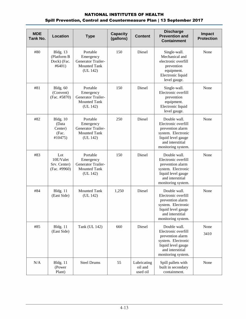
NATIONAL INSTITUTES OF HEALTH
Spill Prevention, Control and Countermeasure Plan | 13 September 2017
4-13
MDE Tank No.
Location Type Capacity (gallons)
Content Discharge
Prevention and Containment
Impact Protection
#80 Bldg. 13
(Platform B
Dock) (Fac.
#6401)
Portable
Emergency
Generator Trailer-
Mounted Tank
(UL 142)
150 Diesel Single-wall.
Mechanical and
electronic overfill
prevention
equipment.
Electronic liquid
level gauge.
None
#81 Bldg. 60
(Convent)
(Fac. #5870)
Portable
Emergency
Generator Trailer-
Mounted Tank
(UL 142)
150 Diesel Single-wall.
Electronic overfill
prevention
equipment.
Electronic liquid
level gauge.
None
#82 Bldg. 10
(Data
Center)
(Fac.
#10475)
Portable
Emergency
Generator Trailer-
Mounted Tank
(UL 142)
250 Diesel Double wall.
Electronic overfill
prevention alarm
system. Electronic
liquid level gauge
and interstitial
monitoring system.
None
#83 Lot
10E/Valet
Srv. Center)
(Fac. #9960)
Portable
Emergency
Generator Trailer-
Mounted Tank
(UL 142)
150 Diesel Double wall.
Electronic overfill
prevention alarm
system. Electronic
liquid level gauge
and interstitial
monitoring system.
None
#84 Bldg. 11
(East Side) Mounted Tank
(UL 142) 1,250 Diesel Double wall.
Electronic overfill
prevention alarm
system. Electronic
liquid level gauge
and interstitial
monitoring system.
None
#85 Bldg. 11
(East Side) Tank (UL 142) 660 Diesel Double wall.
Electronic overfill
prevention alarm
system. Electronic
liquid level gauge
and interstitial
monitoring system.
None
3410
N/A Bldg. 11
(Power
Plant)
Steel Drums 55 Lubricating
oil and
used oil
Spill pallets with
built in secondary
containment.
None
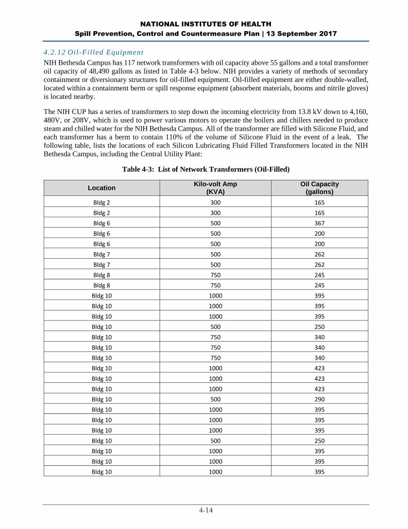
NATIONAL INSTITUTES OF HEALTH
Spill Prevention, Control and Countermeasure Plan | 13 September 2017
4-14
4.2.12 Oil-Filled Equipment
NIH Bethesda Campus has 117 network transformers with oil capacity above 55 gallons and a total transformer
oil capacity of 48,490 gallons as listed in Table 4-3 below. NIH provides a variety of methods of secondary
containment or diversionary structures for oil-filled equipment. Oil-filled equipment are either double-walled,
located within a containment berm or spill response equipment (absorbent materials, booms and nitrile gloves)
is located nearby.
The NIH CUP has a series of transformers to step down the incoming electricity from 13.8 kV down to 4,160,
480V, or 208V, which is used to power various motors to operate the boilers and chillers needed to produce
steam and chilled water for the NIH Bethesda Campus. All of the transformer are filled with Silicone Fluid, and
each transformer has a berm to contain 110% of the volume of Silicone Fluid in the event of a leak. The
following table, lists the locations of each Silicon Lubricating Fluid Filled Transformers located in the NIH
Bethesda Campus, including the Central Utility Plant:
Table 4-3: List of Network Transformers (Oil-Filled)
Location Kilo-volt Amp
(KVA) Oil Capacity
(gallons)
Bldg 2 300 165
Bldg 2 300 165
Bldg 6 500 367
Bldg 6 500 200
Bldg 6 500 200
Bldg 7 500 262
Bldg 7 500 262
Bldg 8 750 245
Bldg 8 750 245
Bldg 10 1000 395
Bldg 10 1000 395
Bldg 10 1000 395
Bldg 10 500 250
Bldg 10 750 340
Bldg 10 750 340
Bldg 10 750 340
Bldg 10 1000 423
Bldg 10 1000 423
Bldg 10 1000 423
Bldg 10 500 290
Bldg 10 1000 395
Bldg 10 1000 395
Bldg 10 1000 395
Bldg 10 500 250
Bldg 10 1000 395
Bldg 10 1000 395
Bldg 10 1000 395
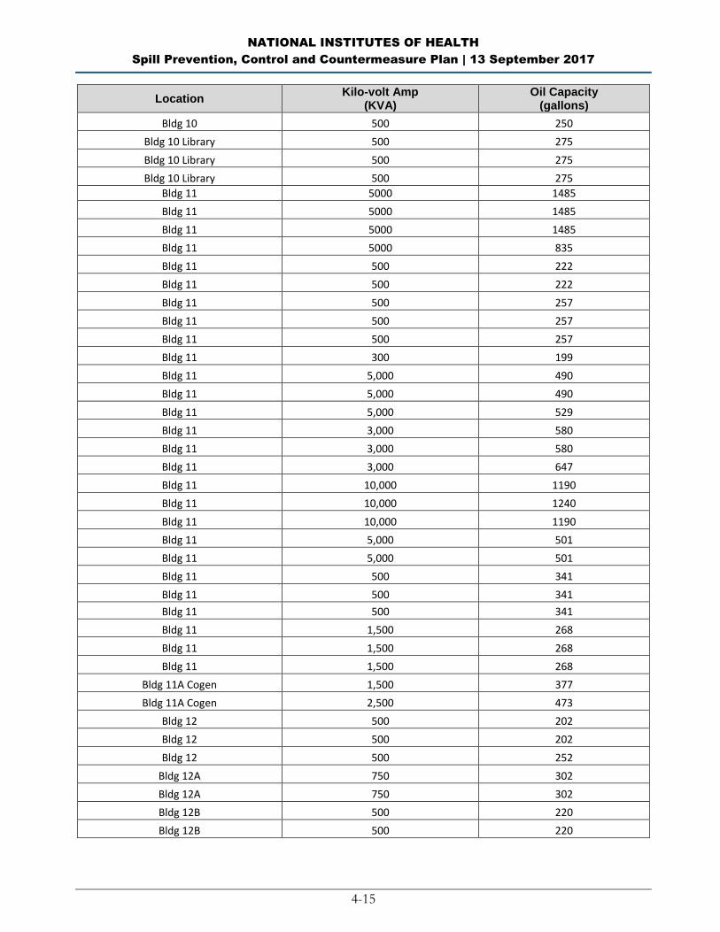
NATIONAL INSTITUTES OF HEALTH
Spill Prevention, Control and Countermeasure Plan | 13 September 2017
4-15
Location Kilo-volt Amp
(KVA) Oil Capacity
(gallons)
Bldg 10 500 250
Bldg 10 Library 500 275
Bldg 10 Library 500 275
Bldg 10 Library 500 275
Bldg 11 5000 1485
Bldg 11 5000 1485
Bldg 11 5000 1485
Bldg 11 5000 835
Bldg 11 500 222
Bldg 11 500 222
Bldg 11 500 257
Bldg 11 500 257
Bldg 11 500 257
Bldg 11 300 199
Bldg 11 5,000 490
Bldg 11 5,000 490
Bldg 11 5,000 529
Bldg 11 3,000 580
Bldg 11 3,000 580
Bldg 11 3,000 647
Bldg 11 10,000 1190
Bldg 11 10,000 1240
Bldg 11 10,000 1190
Bldg 11 5,000 501
Bldg 11 5,000 501
Bldg 11 500 341
Bldg 11 500 341
Bldg 11 500 341
Bldg 11 1,500 268
Bldg 11 1,500 268
Bldg 11 1,500 268
Bldg 11A Cogen 1,500 377
Bldg 11A Cogen 2,500 473
Bldg 12 500 202
Bldg 12 500 202
Bldg 12 500 252
Bldg 12A 750 302
Bldg 12A 750 302
Bldg 12B 500 220
Bldg 12B 500 220
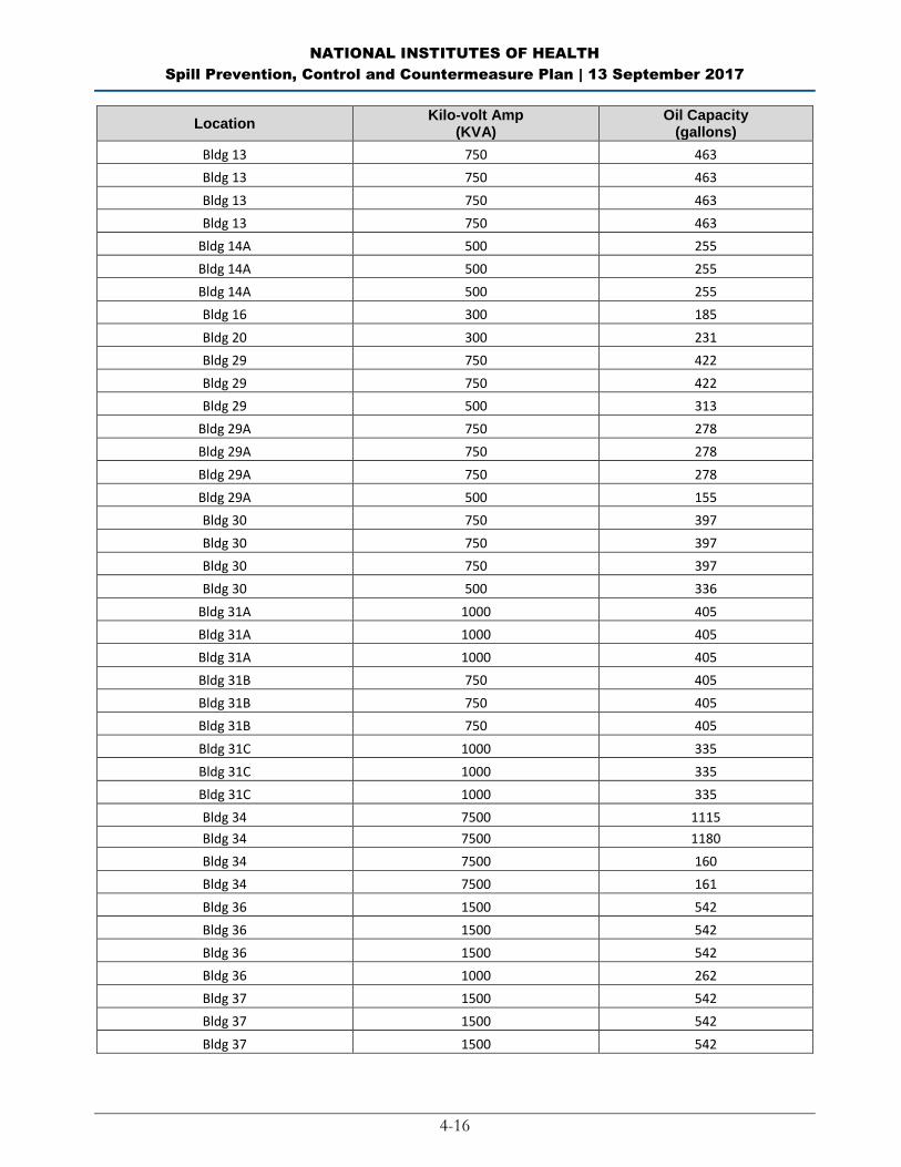
NATIONAL INSTITUTES OF HEALTH
Spill Prevention, Control and Countermeasure Plan | 13 September 2017
4-16
Location Kilo-volt Amp
(KVA) Oil Capacity
(gallons)
Bldg 13 750 463
Bldg 13 750 463
Bldg 13 750 463
Bldg 13 750 463
Bldg 14A 500 255
Bldg 14A 500 255
Bldg 14A 500 255
Bldg 16 300 185
Bldg 20 300 231
Bldg 29 750 422
Bldg 29 750 422
Bldg 29 500 313
Bldg 29A 750 278
Bldg 29A 750 278
Bldg 29A 750 278
Bldg 29A 500 155
Bldg 30 750 397
Bldg 30 750 397
Bldg 30 750 397
Bldg 30 500 336
Bldg 31A 1000 405
Bldg 31A 1000 405
Bldg 31A 1000 405
Bldg 31B 750 405
Bldg 31B 750 405
Bldg 31B 750 405
Bldg 31C 1000 335
Bldg 31C 1000 335
Bldg 31C 1000 335
Bldg 34 7500 1115
Bldg 34 7500 1180
Bldg 34 7500 160
Bldg 34 7500 161
Bldg 36 1500 542
Bldg 36 1500 542
Bldg 36 1500 542
Bldg 36 1000 262
Bldg 37 1500 542
Bldg 37 1500 542
Bldg 37 1500 542

NATIONAL INSTITUTES OF HEALTH
Spill Prevention, Control and Countermeasure Plan | 13 September 2017
4-17
Location Kilo-volt Amp
(KVA) Oil Capacity
(gallons)
Bldg 37 1000 542
Bldg 38 750 255
Bldg 38 750 255
Bldg 38 750 255
MLP6 750 275
Bldg 41 750 256
Bldg 41 750 256
Bldg 41 750 256
Bldg 46 225 85
Bldg 52 750 349
Bldg 52 750 355
Bldg 54 225 241
NIH Bethesda Campus has hydraulic elevator reservoirs exceeding 55-gallons of oil capacity. The total oil
capacity of hydraulic elevator reservoirs is 14,832 gallons. Table 4-4 lists the locations of all hydraulic
elevator reservoirs at the NIH Bethesda Campus:
Table 4-4: List of Hydraulic Elevator Reservoirs
Location Hydraulic Oil Capacity
(gallons)
Bldg 2 199
Bldg 2 281
Bldg 10 635
Bldg 10 310
Bldg 10 336
Bldg 10 148
Bldg 10 207
Bldg 10 232
Bldg 10 268
Bldg 13 258
Bldg 13 326
Bldg 35 890
Bldg 38 981
Bldg 38 794
Bldg 38 340
Bldg 41 222
Bldg 45 751
Bldg 45 240
Bldg 50 358
Bldg 51 216

NATIONAL INSTITUTES OF HEALTH
Spill Prevention, Control and Countermeasure Plan | 13 September 2017
4-18
Location Hydraulic Oil Capacity
(gallons)
Bldg 60 164
Bldg 62 172
Bldg 65 233
Bldg 66 453
Bldg 66 453
Bldg 82 182
Bldg 15K 241
Bldg 31A 189
Bldg 31C 213
Bldg 62A 237
Bldg 6B 180
Bldg 6B 420
Bldg 6B 420
Bldg 6B 349
Bldg 6B 469
MLP-11 303
MLP-8 684
MLP-9 387
MLP-9 387
MLP-9 387
MLP-9 387
4.3 Transfer Operations, Pumping and In-Plant Processes (40 CFR 112.8(d))
Transfer operations at this facility include:
The transfer of oil through aboveground and buried piping from ASTs to buildings.
The transfer of oil from tanker trucks to the ASTs and emergency generators.
The transfer of oil from portable trailer-mounted fuel dispenser tank to emergency generators
The filling of vehicle tanks from the exempt USTs at the fuel dispensing area.
All aboveground piping and valves are examined monthly to assess their condition. Inspection includes
aboveground valves, piping, appurtenances, expansion joints, valve glands and bodies, catch pans, pipeline
supports, locking of valves, and metal surfaces. Observations are noted on the monthly inspection checklist
provided in this Plan. AST with underground piping are tested annually for precision tightness, in accordance
with Maryland requirements at COMAR 26.10.02.01-.11.
Warning signs are posted at appropriate locations throughout the facility to prevent vehicles from damaging
aboveground piping and related appurtenances (40 CFR 112.8(d)(5)). Most of the aboveground piping is
located within areas that are not accessible to vehicular traffic (e.g., inside a diked area). Brightly painted
bollards are placed where needed to prevent vehicular collisions with AST-related equipment.

NATIONAL INSTITUTES OF HEALTH
Spill Prevention, Control and Countermeasure Plan | 13 September 2017
4-19
All buried piping at NIH is cathodically protected against corrosion and provided with a protective wrapping
and coating. When a section of buried lined is exposed, it is carefully examined for deterioration. If corrosion
damage is found, additional examination and corrective action is taken as deemed appropriate considering the
magnitude of the damage. Additionally, NIH conducts integrity and leak testing of buried piping at the time of
installation, modification, construction, relocation or replacement. Records of all tests are maintained at the
facility for at least three years.
All pipe supports are designed to minimize abrasion and corrosion and to allow for expansion and contraction.
Pipe supports are visually inspected during the monthly inspection.
Lines that are not in service or are on standby for an extended prior of time are capped or blank-flanged and
marked as to their origin.

NATIONAL INSTITUTES OF HEALTH
Spill Prevention, Control and Countermeasure Plan | 13 September 2017
4-20
BLANK PAGE
NATIONAL INSTITUTES OF HEALTH
Spill Prevention, Control and Countermeasure Plan | 13 September 2017
5-1
PART 5: Discharge Response
This section describes the response and cleanup procedures in the event of an oil discharge. The uncontrolled
discharge of oil to groundwater, surface water, or soil is prohibited by state and federal laws. Immediate action
must be taken to control, contain, and recover discharged product.
In general, the following steps are taken:
Eliminate potential spark sources;
If possible and safe to do so, identify and shut down source of the discharge to stop the flow;
Contain the discharge with sorbents, berms, fences, trenches, sandbags, or other material;
Contact immediate supervisor/management of the spill and/or release;
Contact William Floyd, Director of DEP, Mark Miller, Chief of DEP-ECB or designee;
Contact the NIH Fire Department for assistance in containing oil discharges;
Contact the spill response and cleanup contractor listed in Emergency Contacts in Appendix F;
Contact the Maryland Department of Environment and the response organization; and
Collect and dispose of recovered products according to regulation.
For the purpose of establishing appropriate response procedures, this SPCC Plan classifies discharges as either
“minor” or “major,” depending on the volume and characteristics of the material released.
William Floyd, Director of DEP, is the Designated Person and responsible for coordinating spill response
measures. If William Floyd is not available, Mark Miller, Chief of DEP-ECB, is the alternate Designated
Person responsible for coordinating spill response measures. The NIH Fire Department provides assistance in
responding to and cleaning up oil spills.
A list of Emergency Contacts is provided in Appendix F. The list is also posted at prominent locations
throughout the facility. A list of discharge response material kept at the facility is included in Appendix H.
NIH personnel will complete the Incident Reporting Form provided in Appendix K to document the spill and
spill response and submit to DEP.
5.1 Response to a Minor Discharge
A “minor” discharge is defined as one that poses no significant harm (or threat) to human health and safety or
to the environment. Minor discharges are generally those where:
The quantity of product discharged is small (e.g., may involve less than 10 gallons of oil);
Discharged material is easily stopped and controlled at the time of the discharge;
Discharge is localized near the source;
Discharged material is not likely to reach water;
There is little risk to human health or safety; and
There is little risk of fire or explosion.

NATIONAL INSTITUTES OF HEALTH
Spill Prevention, Control and Countermeasure Plan | 13 September 2017
5-2
Minor discharges can usually be cleaned up by NIH personnel or NIH contractor personnel. The following
guidelines apply:
Immediately notify the Director of DEP. If not available, notify the Chief of DEP-ECB or a designee.
Under the direction of the Director of DEP, Chief of DEP-ECB or a designee, contain the discharge
with discharge response materials and equipment. Place discharge debris in properly labeled waste
containers.
The Director of DEP, Chief of DEP-ECB or a designee will complete the discharge notification form
(Appendix G) and attach a copy to this SPCC Plan.
5.2 Response to a Major Discharge
A “major” discharge is defined as one that cannot be safely controlled or cleaned up by facility personnel, such
as when:
The discharge is large enough to spread beyond the immediate discharge area;
The discharged material enters the storm drain and potentially reaches water;
The discharge requires special equipment or training to clean up;
The discharged material poses a hazard to human health, safety or the environment; or
There is a danger of fire or explosion.
In the event of a major discharge, the following guidelines apply:
All workers must immediately evacuate the discharge site via the designated exit routes and move to
the designated staging areas at a safe distance from the discharge. Exit routes are included on the facility
diagram and posted in the maintenance building, in the office building, and on the outside wall of the
outside shed that contains the spill response equipment.
Notify the Director of DEP. If the Director of DEP is not present at the facility, the Chief of DEP-ECB
or a designee must be notified of the discharge and has authority to initiate notification and response.
Certain notifications are dependent on the circumstances and type of discharge. For example, if oil
reaches a sanitary sewer, the Washington Suburban Sanitary Commission should be notified
immediately. A discharge that threatens Rock Creek or the Potomac River may require immediate
notification to downstream users.
The Director of DEP, Chief of DEP-ECB or a designee must call for medical assistance if workers are
injured.
The Director of DEP, Chief of DEP-ECB or a designee must notify the NIH Fire Department or NIH
Police Department.
The Director of DEP, Chief of DEP-ECB or a designee must coordinate with DFOM to call the spill
response and cleanup contractor listed in the Emergency Contacts list in Appendix F.
If spill responses is associated with the CUP, then the DEP Director, Branch Chief, Compliance Branch
or a designee must coordinate with the NIH DTR Utilities Generation Chief to call the spill response
and cleanup contractors listed in the Emergency Contacts list in Appendix F.
NATIONAL INSTITUTES OF HEALTH
Spill Prevention, Control and Countermeasure Plan | 13 September 2017
5-3
The Director of DEP, Chief of DEP-ECB or a designee must immediately contact the Maryland
Department of Environment (866-633-4686) and the National Response Center (888-424-8802).
The Director of DEP, Chief of DEP-ECB or a designee must record the call on the Discharge
Notification form in Appendix G and attach a copy to this SPCC Plan.
The Director of DEP, Chief of DEP-ECB or a designee coordinates cleanup and obtains assistance from
a cleanup contractor or other response organization as necessary.
5.3 Waste Disposal
Wastes resulting from a minor discharge response will be containerized in impervious bags, drums, or buckets.
The Waste Resource and Recovery Branch (WRRB) of DEP will characterize the waste and ensure its proper
disposal so that it is removed from NIH Bethesda Campus properly. All contractor-associated paperwork (e.g.,
non-hazardous waste manifest) will be signed by the DEP designee prior to waste removal off the NIH property.
Wastes resulting from a major discharge response will be removed and disposed of by WRRB’s Chemical
Waste Contractor.
5.4 Discharge Notification
Any size discharge (i.e., one that creates a sheen, emulsion, or sludge) that affects or threatens to affect
navigable waters or adjoining shorelines must be reported immediately to the National Response Center (1-
800-424-8802). The Center is staffed 24 hours a day. MDE must be notified within two hours of discovery of
release or spill.
A summary sheet is included in Appendix G to facilitate reporting. The person reporting the discharge must
provide the following information to the National Response Center and MDE Oil Control Program:
Name, location, organization, and telephone number
Name and address of the party responsible for the incident
Date and time of the incident
Location of the incident
Source and cause of the release or discharge
Types of material(s) released or discharged
Quantity of materials released or discharged
Danger or threat posed by the release or discharge
Number and types of injuries (if any)
Media affected or threatened by the discharge (i.e., water, land, air)
Weather conditions at the incident location
Any other information that may help emergency personnel respond to the incident
Contact information for reporting a discharge to the appropriate authorities is listed in Appendix F and is also
posted in prominent locations throughout the facility (e.g., in the office building, in the maintenance building,
and at the loading rack/unloading area).

NATIONAL INSTITUTES OF HEALTH
Spill Prevention, Control and Countermeasure Plan | 13 September 2017
5-4
In addition to the above reporting, 40 CFR 112.4 requires that information be submitted to the United States
Environmental Protection Agency (EPA) Regional Administrator in charge of oil pollution control activities
(see contact information in Appendix G) whenever the facility discharges (as defined in 40 CFR 112.1(b)) more
than 1,000 gallons of oil in a single event, or discharges more than 42 gallons of oil in each of two discharge
incidents within a 12-month period. The following information must be submitted to the EPA Region 3
Administrator and MDE within 60 days:
Name of the facility;
Name of the owner/operator;
Location of the facility;
Maximum storage or handling capacity and normal daily throughput;
Corrective action and countermeasures taken, including a description of equipment repairs and
replacements;
Description of facility, including maps, flow diagrams, and topographical maps;
Cause of the discharge(s) to navigable waters and adjoining shorelines, including a failure analysis of
the system and subsystem in which the failure occurred;
Additional preventive measures taken or contemplated to minimize possibility of recurrence; and
Other pertinent information requested by the Regional Administrator.
A standard report for submitting the information to the EPA Regional Administrator is included in Appendix I
of this Plan.
5.5 Cleanup Contractors and Equipment Suppliers
Contact information for specialized spill response and cleanup contractors are provided in Appendix F. The
inventory of discharge response supplies and equipment, including spill kits, is provided in Appendix H of this
Plan. The inventory is verified on a monthly basis. Additional cleanup is conducted by DEP Chemical Service
Contractor. Additional supplies and equipment may be ordered from the DEP Chemical Service Contractor.

NATIONAL INSTITUTES OF HEALTH
Spill Prevention, Control and Countermeasure Plan | 13 September 2017
6-1
PART 6: APPENDICES
APPENDIX A: Site Plan/Facility Diagrams
Figure A-1: NIH Bethesda Campus and Surrounding Area
Figure A-2: Oil Filled Storage Tanks
Figure A-3: Hydraulic Lifts and Transformers
APPENDIX B: Substantial Harm Determination APPENDIX C: Facility Inspection Checklists
Monthly Inspection Checklist
Annual Facility Inspection Checklist
APPENDIX D: Record of Containment Dike Drainage APPENDIX E: Record of Annual Discharge Prevention Briefings and Training APPENDIX F: Emergency Contacts APPENDIX G: Discharge Notification Form APPENDIX H: Discharge Response Equipment Inventory
Table 1: Hazardous Waste Storage Units
(4)
Table2: Emergency Equipment within
Building 21
Table 3: Building 26T Emergency
Equipment
Table 4: Building 21 Radioactive Waste
Management Facility Emergency
Equipment
Table 5: NIH Fire Department Hazardous
Materials Unit – Cab
Table 6: NIH Fire Department Hazardous
Materials Unit - Drivers Side
Table 7: NIH Fire Department Hazardous
Materials Unit - Rear Compartment
Table 8: NIH Fire Department Hazardous
Materials Unit - Officers Side
Compartment
Table 9: NIH Fire Department Hazardous
Materials Unit - Driver Side Compartment
#1 and #2
Table 10: NIH Fire Department
Hazardous Materials Unit - Driver Side
Compartment Decon Tub
Table 11: NIH Fire Department
Hazardous Materials Unit - Driver Side
Compartment #3
Table 12: NIH Fire Department
Hazardous Materials Unit - Driver Side
Compartment #4 (D-4)
Table 13: NIH Fire Department
Hazardous Materials Unit - Drivers Side
Compartment #5 (D-5)
Table 14: NIH Fire Department
Hazardous Materials Unit - Drivers Side
Compartment #6 (D-6)
Table 15: NIH Fire Department
Hazardous Materials Unit - Driver Side
Belly Compartment #7
Table 16: NIH Fire Department
Hazardous Materials Unit - Driver Side
Belly Compartment #8
Table 17: NIH Fire Department
Hazardous Materials Unit - Rear
Compartment
Table 18: NIH Fire Department
Hazardous Materials Unit - Officers Side
Compartment #1 (O-1)
Table 19: NIH Fire Department
Hazardous Materials Unit - Officers Side
Compartment #2 (O-2)
Table 20: NIH Fire Department
Hazardous Materials Unit - Officers Side
Compartment #3 (O-3)
Table 21: NIH Fire Department
Hazardous Materials Unit - Officers Side
Compartment #4 (O-4)
Table 22: NIH Fire Department
Hazardous Materials Unit - Officers Side
Compartment #5 (O-5)

NATIONAL INSTITUTES OF HEALTH
Spill Prevention, Control and Countermeasure Plan | 13 September 2017
6-2
Table 23: NIH Fire Department
Hazardous Materials Unit - Officers Side
Compartment #6 (O-6)
Table 24: NIH Fire Department
Hazardous Materials Unit - Officers Side
Belly Compartment #7 (O-7)
Table 25: NIH Fire Department
Hazardous Materials Unit - Officers Side
Belly Compartment #8 (O-8)
Table 26: NIH Fire Department
Hazardous Materials Unit - Inside Cab
Table 27: NIH Fire Department
Hazardous Materials Unit - Front Off.
Side Coffin Comp. #1 (C-1)
Table 28: NIH Fire Department
Hazardous Materials Unit - Rear Off. Side
Coffin Comp. #2 (C-2)
Table 29: NIH Fire Department
Hazardous Materials Unit - Middle Coffin
Comp. #3 (C-3)
Table 30: NIH Fire Department
Hazardous Materials Unit - Front Dr. Side
Coffin Comp. #1 (C-4)
Table 31: NIH Fire Department
Hazardous Materials Unit - Rear Dr. Side
Coffin Comp. #2 (C-5)
APPENDIX I: Agency Notification Standard Report APPENDIX J: Compliance Plan APPENDIX K: Incident Reporting Form

NATIONAL INSTITUTES OF HEALTH
Spill Prevention, Control and Countermeasure Plan | 13 September 2017
6-3
APPENDIX A: Site Plan/Facility Diagrams
Figure A-1: NIH Bethesda Campus and Surrounding Area
N

NATIONAL INSTITUTES OF HEALTH
Spill Prevention, Control and Countermeasure Plan | 13 September 2017
6-4
BLANK PAGE

NATIONAL INSTITUTES OF HEALTH
Spill Prevention, Control and Countermeasure Plan | 13 September 2017
6-5
Figure A-2: Oil Filled Storage Tanks
CLICK ONTO HYPERLINK BELOW TO ACCESS FULL-SIZE MAP at
https://orfweb.od.nih.gov/sites/dep/Documents%20and%20Records/NIH%20_Tanks_0906%202.pdf

NATIONAL INSTITUTES OF HEALTH
Spill Prevention, Control and Countermeasure Plan | 13 September 2017
6-6
BLANK PAGE
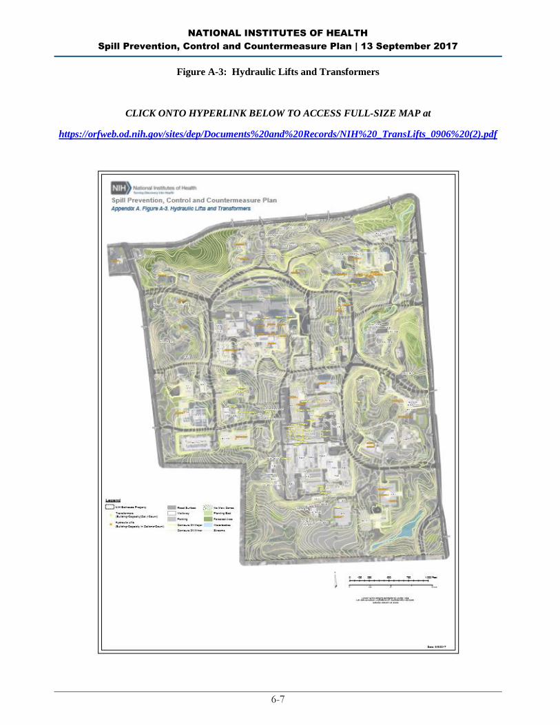
NATIONAL INSTITUTES OF HEALTH
Spill Prevention, Control and Countermeasure Plan | 13 September 2017
6-7
Figure A-3: Hydraulic Lifts and Transformers
CLICK ONTO HYPERLINK BELOW TO ACCESS FULL-SIZE MAP at
https://orfweb.od.nih.gov/sites/dep/Documents%20and%20Records/NIH%20_TransLifts_0906%20(2).pdf

NATIONAL INSTITUTES OF HEALTH
Spill Prevention, Control and Countermeasure Plan | 13 September 2017
6-8
BLANK PAGE
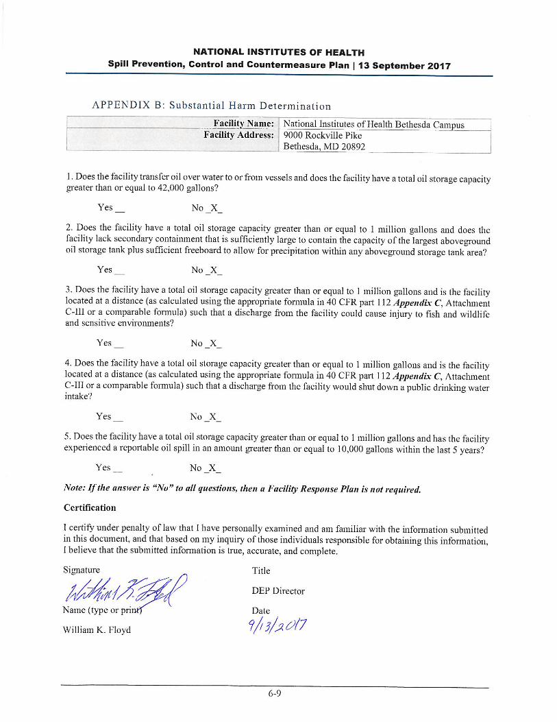

NATIONAL INSTITUTES OF HEALTH
Spill Prevention, Control and Countermeasure Plan | 13 September 2017
6-10
BLANK PAGE

NATIONAL INSTITUTES OF HEALTH
Spill Prevention, Control and Countermeasure Plan | 13 September 2017
6-11
APPENDIX C: Facili ty Inspection Checklists
The following checklists are to be used for monthly and annual inspections. Completed checklists must be
signed by the inspector and maintained at the facility, with this SPCC Plan, for at least three years.
Monthly Inspection Checklist
Annual Facility Inspection Checklist
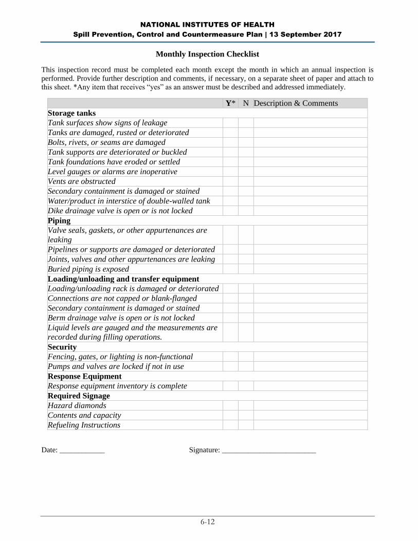
NATIONAL INSTITUTES OF HEALTH
Spill Prevention, Control and Countermeasure Plan | 13 September 2017
6-12
Monthly Inspection Checklist
This inspection record must be completed each month except the month in which an annual inspection is
performed. Provide further description and comments, if necessary, on a separate sheet of paper and attach to
this sheet. *Any item that receives “yes” as an answer must be described and addressed immediately.
Y* N Description & Comments
Storage tanks
Tank surfaces show signs of leakage
Tanks are damaged, rusted or deteriorated
Bolts, rivets, or seams are damaged
Tank supports are deteriorated or buckled
Tank foundations have eroded or settled
Level gauges or alarms are inoperative
Vents are obstructed
Secondary containment is damaged or stained
Water/product in interstice of double-walled tank
Dike drainage valve is open or is not locked
Piping
Valve seals, gaskets, or other appurtenances are
leaking
Pipelines or supports are damaged or deteriorated
Joints, valves and other appurtenances are leaking
Buried piping is exposed
Loading/unloading and transfer equipment
Loading/unloading rack is damaged or deteriorated
Connections are not capped or blank-flanged
Secondary containment is damaged or stained
Berm drainage valve is open or is not locked
Liquid levels are gauged and the measurements are
recorded during filling operations.
Security
Fencing, gates, or lighting is non-functional
Pumps and valves are locked if not in use
Response Equipment
Response equipment inventory is complete
Required Signage
Hazard diamonds
Contents and capacity
Refueling Instructions
Date: ____________ Signature: _________________________

NATIONAL INSTITUTES OF HEALTH
Spill Prevention, Control and Countermeasure Plan | 13 September 2017
6-13
Annual Facility Inspection Checklist
This inspection record must be completed each year. If any response requires further elaboration, provide
comments in Description & Comments space provided. Further description and comments, if necessary, must
be provided on a separate sheet of paper and attached to this sheet. *Any item that receives “yes” as an answer
must be described and addressed immediately.
Y* N Description & Comments
Storage tanks
Tank surfaces show signs of leakage
Tank is damaged, rusted or deteriorated
Bolts, rivets or seams are damaged
Tank supports are deteriorated or buckled
Tank foundations have eroded or settled
Level gauges or alarms are inoperative
Vents are obstructed
Concrete dike
Secondary containment is stained
Dike drainage valve is open or is not locked
Dike walls or floors are cracked or are
separating
Dike is not retaining water (following large
rainfall)
Piping
Valve seals or gaskets are leaking
Pipelines or supports are damaged or
deteriorated
Joints, valves and other appurtenances are
leaking
Buried piping is exposed
Out-of-service pipes are not capped
Warning signs are missing or damaged
Loading/unloading and transfer equipment
Loading/unloading rack is damaged or
deteriorated
Connections are not capped or blank-flanged
Rollover berm is damaged or stained
Berm drainage valve is open or is not locked
Drip pans have accumulated oil or are leaking
Security
Fencing, gates, or lighting is non-functional
Pumps and valves are not locked (and not in use)
Response equipment
Response equipment inventory is incomplete

NATIONAL INSTITUTES OF HEALTH
Spill Prevention, Control and Countermeasure Plan | 13 September 2017
6-14
Annual reminders:
Hold SPCC Briefing for all oil-handling personnel (and update briefing log in the Plan); and
Check contact information for key employees and response/cleanup contractors and update them in the Plan
as needed;
Additional Remarks:
Date: _______________ Signature: _____________________
NATIONAL INSTITUTES OF HEALTH
Spill Prevention, Control and Countermeasure Plan | 13 September 2017
6-15
APPENDIX D: Record of Containment Dike Drainage
This record must be completed when rainwater from diked areas is drained into a storm drain or into an open
watercourse, lake, or pond, and bypasses the water treatment system. The bypass valve must normally be sealed
in closed position. It must be opened and resealed following drainage under responsible supervision.
Date Diked Area Presence of Oil Time Started Time Finished Signature

NATIONAL INSTITUTES OF HEALTH
Spill Prevention, Control and Countermeasure Plan | 13 September 2017
6-16
BLANK PAGE
NATIONAL INSTITUTES OF HEALTH
Spill Prevention, Control and Countermeasure Plan | 13 September 2017
6-17
APPENDIX E: Record of Annual Discharge Prevention Briefings and Training
Briefings will be scheduled and conducted by the facility owner or operator for operating personnel at regular
intervals to ensure adequate understanding of this SPCC Plan. The briefings will also highlight and describe
known discharge events or failures, malfunctioning components, and recently implemented precautionary
measures and best practices. Personnel will also be instructed in operation and maintenance of equipment to
prevent the discharge of oil, and in applicable pollution laws, rules, and regulations. Facility operators and other
personnel will have an opportunity during the briefings to share recommendations concerning health, safety,
and environmental issues encountered during facility operations.
Date Subjects Covered Employees in Attendance Instructor(s)
NATIONAL INSTITUTES OF HEALTH
Spill Prevention, Control and Countermeasure Plan | 13 September 2017
6-18
BLANK PAGE
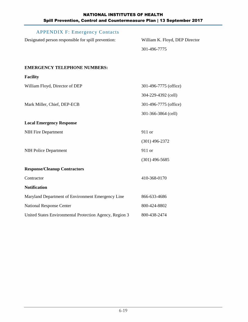
NATIONAL INSTITUTES OF HEALTH
Spill Prevention, Control and Countermeasure Plan | 13 September 2017
6-19
APPENDIX F: Emergency Contacts
Designated person responsible for spill prevention: William K. Floyd, DEP Director
301-496-7775
EMERGENCY TELEPHONE NUMBERS:
Facility
William Floyd, Director of DEP 301-496-7775 (office)
304-229-4392 (cell)
Mark Miller, Chief, DEP-ECB 301-496-7775 (office)
301-366-3864 (cell)
Local Emergency Response
NIH Fire Department 911 or
(301) 496-2372
NIH Police Department 911 or
(301) 496-5685
Response/Cleanup Contractors
Contractor 410-368-0170
Notification
Maryland Department of Environment Emergency Line 866-633-4686
National Response Center 800-424-8802
United States Environmental Protection Agency, Region 3 800-438-2474

NATIONAL INSTITUTES OF HEALTH
Spill Prevention, Control and Countermeasure Plan | 13 September 2017
6-20
BLANK PAGE

NATIONAL INSTITUTES OF HEALTH
Spill Prevention, Control and Countermeasure Plan | 13 September 2017
6-21
APPENDIX G: Discharge Notification Form
Part A: Discharge Information
General information when reporting a spill to outside authorities:
Name: National Institutes of Health Bethesda Campus
Address: 9000 Rockville Pike
Bethesda, MD 20892
Telephone: (301) 496-7775
Primary Contact: William K. Floyd, Director, Division of Environmental Protection
Work: (301) 496-7775
Cell (24 hrs): (304) 229-4392
Type of oil: Discharge Date and Time:
Quantity released: Discovery Date and Time:
Quantity released to a waterbody: Discharge Duration:
Location/Source:
Actions taken to stop, remove, and mitigate impacts of the discharge:
Affected media:
__ air
__ water
__ soil
__ storm water sewer/POTW
__ dike/berm/oil-water separator
__ other: _________________________
Notification person: Telephone contact:
Business:
24-hr:
Nature of discharges, environmental/health effects, and damages:
Injuries, fatalities or evacuation required?

NATIONAL INSTITUTES OF HEALTH
Spill Prevention, Control and Countermeasure Plan | 13 September 2017
6-22
Part B: Notification Checklist
Date and time Name of person receiving call
Discharge in any amount
William Floyd, DEP Director and
Response Coordinator
(301) 496-7775 (office)
(304) 229-4392 (cell)
Mark Miller, Branch Chief, Compliance
Branch and Alternate Response
Coordinator
(301) 496-2372 (office)
(301) 366-3864 (cell)
Discharge in any amount and affecting (or threatening to affect) a waterbody
NIH Fire Department
(301) 496-2372 or 911
Maryland Department of Environment
(410) 537-3000 (daytime)
(866) 633-4686 (nights/weekends)
National Response Center
(800) 424-8802
NIH Police Department
(301) 496-5685 or 911
Maryland State Fire Marshal
Brian Geraci, Fire Marshal
(410) 653-8980
State Emergency Response Commission
(410) 517-3600

NATIONAL INSTITUTES OF HEALTH
Spill Prevention, Control and Countermeasure Plan | 13 September 2017
6-23
APPENDIX H: Discharge Response Equipment Inventory
The discharge response equipment inventory is verified during the monthly inspection and must be replenished
as needed.
The following is a current list of discharge response equipment:
Table 1
Hazardous Waste Storage Units (4)
Type Quantity
Dry Chemical Fire Extinguisher Systems 1 System per Unit
Sump Basins for Containing Spills with Liquid Sensing Alarms which Activate an External Audible Alarm and Flashing White Light
3 Sump Basins per Unit 3 Sensors per Unit 1 Alarm per Unit
Explosive Blow-out Panels on Rear Wall 3 per Unit
Spill absorbents (booms, pads) Various quantities
Table2
Emergency Equipment within Building 21
Type Quantity
Fire Extinguishers for Metal Fires 2
ABC Fire Extinguishers 5
Chemical Fume Hoods 8
Carcinogen Handling Box 1
Walk-In Solvent Pouring 1 Hood
Walk-In Solvent Glass Crusher 1
Mercury Vacuum 1
Self-Contained Breathing Devices 2 Apparatus
Acid Base Neutralizing Agents Various quantities
Whole face respirators with supply of various cartridges
1 per Employee
Saranex and Tyvek Chemical Contamination Suits (Disposable)
Minimum of 12
Chemical Resistant Gloves (Nitrile) 4 cases
Industrial Vacuum Cleaner with HEPA Filter 2

NATIONAL INSTITUTES OF HEALTH
Spill Prevention, Control and Countermeasure Plan | 13 September 2017
6-24
Table2
Emergency Equipment within Building 21
Room Temperature and Refrigerator Temperature Sensors and Alarms for the
Explosives Holding Room
See Attachment E for Details
Foam Extinguishing System for the Solvent Room (Activated only with Fire Department
Hook-Up) and Class I Electrical Wiring
1
Safety Goggles 1 Per Employee
Electrical Drum Pump 2
Automatic Water sprinkler system for areas other than Solvent and Explosives Handling
Room
Every Room and Hall
Service Area Spill Containment Trenches 2
Eyewash Stations 5
Large Portable Ventilation Fan 1
First Aid Kit 1
Supplied air compressor with air hoses and breathing masks
1 compressor with varying number of hoses and masks
Table 3
Building 26T Emergency Equipment
Type Quantity
ABC Fire Extinguishers 2
Spill Absorbing Material 400 lbs. Minimum 8 Bags
Emergency Shower/Eyewash Station 2
General First Aid Kit 1
Saranex and Tyvek Chemical
Contamination Suits (Disposable)
Minimum of 3
Chemical Resistant Gloves (Nitrile) 1 case
Safety Goggles Minimum 1 per employee
Chemical Fume Hood 4
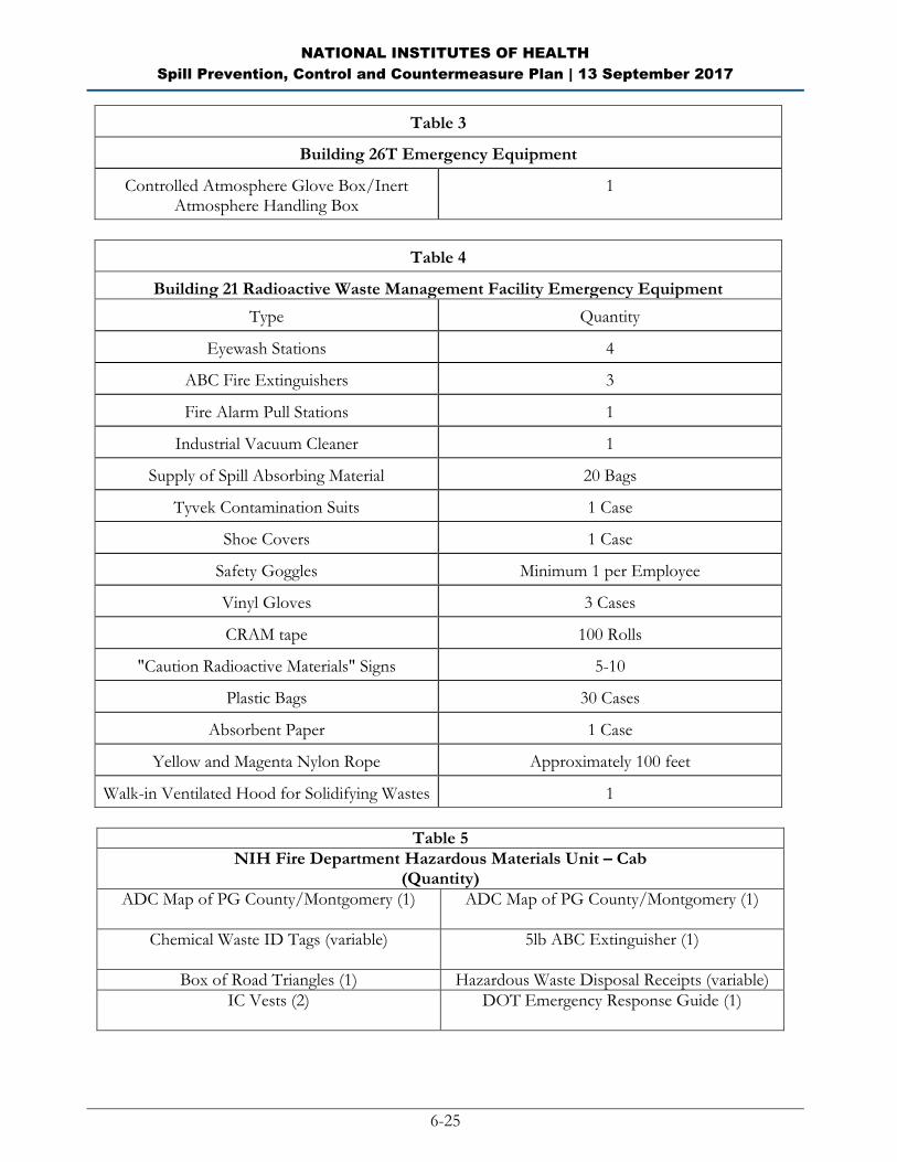
NATIONAL INSTITUTES OF HEALTH
Spill Prevention, Control and Countermeasure Plan | 13 September 2017
6-25
Table 3
Building 26T Emergency Equipment
Controlled Atmosphere Glove Box/Inert Atmosphere Handling Box
1
Table 4
Building 21 Radioactive Waste Management Facility Emergency Equipment
Type Quantity
Eyewash Stations 4
ABC Fire Extinguishers 3
Fire Alarm Pull Stations 1
Industrial Vacuum Cleaner 1
Supply of Spill Absorbing Material 20 Bags
Tyvek Contamination Suits 1 Case
Shoe Covers 1 Case
Safety Goggles Minimum 1 per Employee
Vinyl Gloves 3 Cases
CRAM tape 100 Rolls
"Caution Radioactive Materials" Signs 5-10
Plastic Bags 30 Cases
Absorbent Paper 1 Case
Yellow and Magenta Nylon Rope Approximately 100 feet
Walk-in Ventilated Hood for Solidifying Wastes 1
Table 5
NIH Fire Department Hazardous Materials Unit – Cab (Quantity)
ADC Map of PG County/Montgomery (1)
ADC Map of PG County/Montgomery (1)
Chemical Waste ID Tags (variable)
5lb ABC Extinguisher (1)
Box of Road Triangles (1) Hazardous Waste Disposal Receipts (variable)
IC Vests (2)
DOT Emergency Response Guide (1)
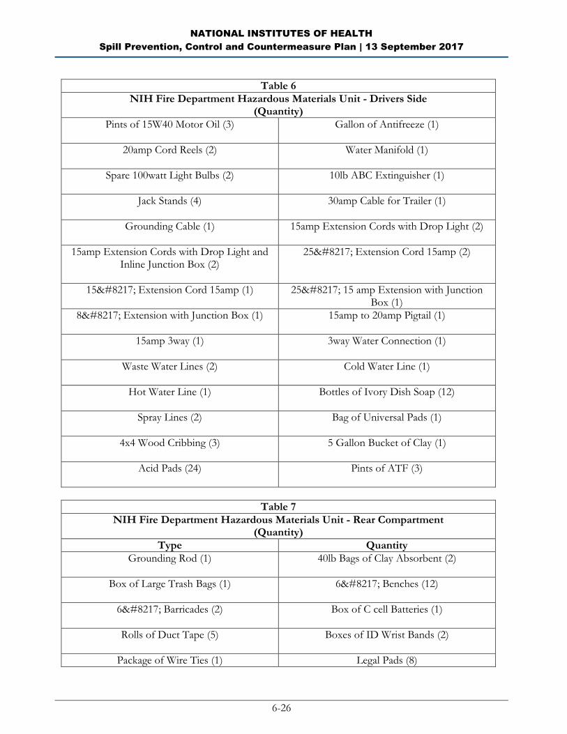
NATIONAL INSTITUTES OF HEALTH
Spill Prevention, Control and Countermeasure Plan | 13 September 2017
6-26
Table 6
NIH Fire Department Hazardous Materials Unit - Drivers Side (Quantity)
Pints of 15W40 Motor Oil (3)
Gallon of Antifreeze (1)
20amp Cord Reels (2)
Water Manifold (1)
Spare 100watt Light Bulbs (2)
10lb ABC Extinguisher (1)
Jack Stands (4)
30amp Cable for Trailer (1)
Grounding Cable (1)
15amp Extension Cords with Drop Light (2)
15amp Extension Cords with Drop Light and Inline Junction Box (2)
25’ Extension Cord 15amp (2)
15’ Extension Cord 15amp (1)
25’ 15 amp Extension with Junction Box (1)
8’ Extension with Junction Box (1)
15amp to 20amp Pigtail (1)
15amp 3way (1)
3way Water Connection (1)
Waste Water Lines (2)
Cold Water Line (1)
Hot Water Line (1)
Bottles of Ivory Dish Soap (12)
Spray Lines (2)
Bag of Universal Pads (1)
4x4 Wood Cribbing (3)
5 Gallon Bucket of Clay (1)
Acid Pads (24)
Pints of ATF (3)
Table 7
NIH Fire Department Hazardous Materials Unit - Rear Compartment (Quantity)
Type Quantity
Grounding Rod (1)
40lb Bags of Clay Absorbent (2)
Box of Large Trash Bags (1)
6’ Benches (12)
6’ Barricades (2)
Box of C cell Batteries (1)
Rolls of Duct Tape (5) Boxes of ID Wrist Bands (2)
Package of Wire Ties (1) Legal Pads (8)
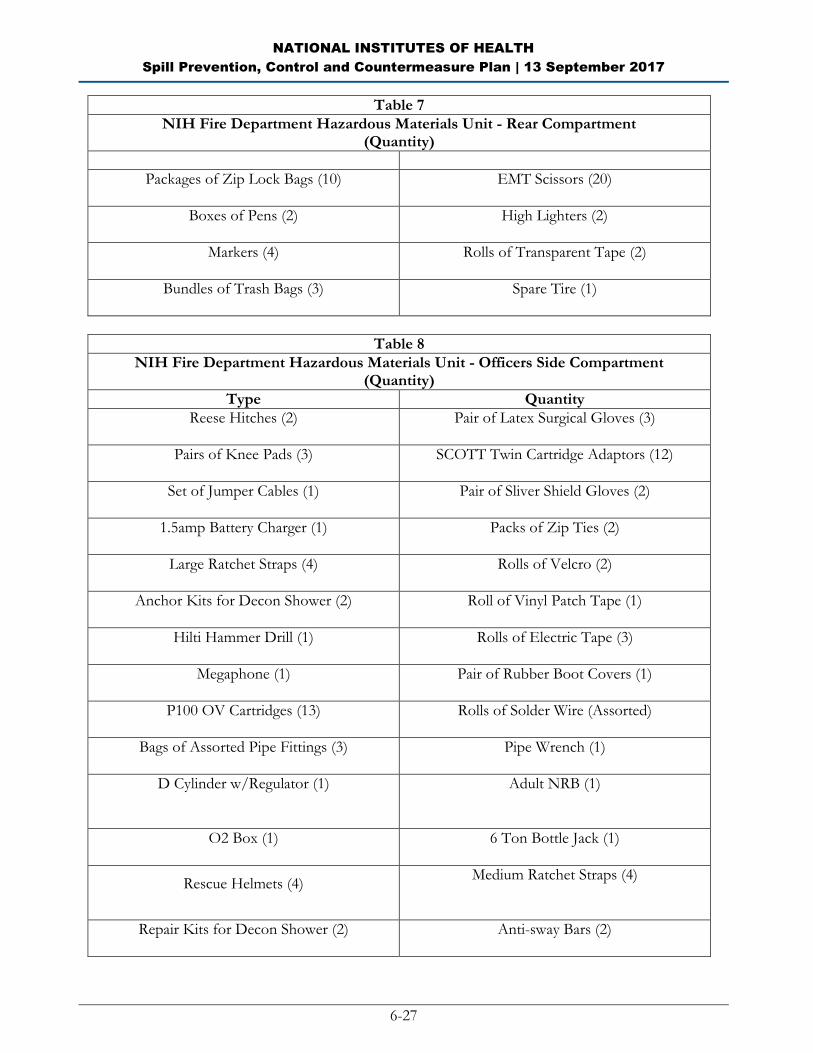
NATIONAL INSTITUTES OF HEALTH
Spill Prevention, Control and Countermeasure Plan | 13 September 2017
6-27
Table 7
NIH Fire Department Hazardous Materials Unit - Rear Compartment (Quantity)
Packages of Zip Lock Bags (10)
EMT Scissors (20)
Boxes of Pens (2)
High Lighters (2)
Markers (4)
Rolls of Transparent Tape (2)
Bundles of Trash Bags (3)
Spare Tire (1)
Table 8
NIH Fire Department Hazardous Materials Unit - Officers Side Compartment (Quantity)
Type Quantity
Reese Hitches (2)
Pair of Latex Surgical Gloves (3)
Pairs of Knee Pads (3)
SCOTT Twin Cartridge Adaptors (12)
Set of Jumper Cables (1)
Pair of Sliver Shield Gloves (2)
1.5amp Battery Charger (1)
Packs of Zip Ties (2)
Large Ratchet Straps (4)
Rolls of Velcro (2)
Anchor Kits for Decon Shower (2)
Roll of Vinyl Patch Tape (1)
Hilti Hammer Drill (1)
Rolls of Electric Tape (3)
Megaphone (1)
Pair of Rubber Boot Covers (1)
P100 OV Cartridges (13)
Rolls of Solder Wire (Assorted)
Bags of Assorted Pipe Fittings (3)
Pipe Wrench (1)
D Cylinder w/Regulator (1)
Adult NRB (1)
O2 Box (1)
6 Ton Bottle Jack (1)
Rescue Helmets (4)
Medium Ratchet Straps (4)
Repair Kits for Decon Shower (2)
Anti-sway Bars (2)
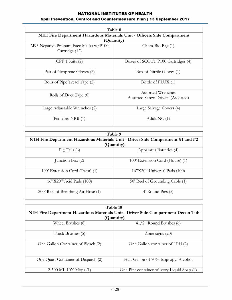
NATIONAL INSTITUTES OF HEALTH
Spill Prevention, Control and Countermeasure Plan | 13 September 2017
6-28
Table 8
NIH Fire Department Hazardous Materials Unit - Officers Side Compartment (Quantity)
M95 Negative Pressure Face Masks w/P100 Cartridge (12)
Chem-Bio Bag (1)
CPF 1 Suits (2)
Boxes of SCOTT P100 Cartridges (4)
Pair of Neoprene Gloves (2)
Box of Nitrile Gloves (1)
Rolls of Pipe Tread Tape (2)
Bottle of FLUX (1)
Rolls of Duct Tape (6)
Assorted Wrenches Assorted Screw Drivers (Assorted)
Large Adjustable Wrenches (2)
Large Salvage Covers (4)
Pediatric NRB (1)
Adult NC (1)
Table 9
NIH Fire Department Hazardous Materials Unit - Driver Side Compartment #1 and #2 (Quantity)
Pig Tails (6)
Apparatus Batteries (4)
Junction Box (2)
100’ Extension Cord (House) (1)
100’ Extension Cord (Twist) (1)
16”X20” Universal Pads (100)
16”X20” Acid Pads (100)
50’ Reel of Grounding Cable (1)
200’ Reel of Breathing Air Hose (1)
4’ Round Pigs (5)
Table 10
NIH Fire Department Hazardous Materials Unit - Driver Side Compartment Decon Tub (Quantity)
Wheel Brushes (8)
41/2” Round Brushes (6)
Truck Brushes (5)
Zone signs (20)
One Gallon Container of Bleach (2)
One Gallon container of LPH (2)
One Quart Container of Dispatch (2)
Half Gallon of 70% Isopropyl Alcohol
2-500 ML 10X Mops (1) One Pint container of ivory Liquid Soap (4)
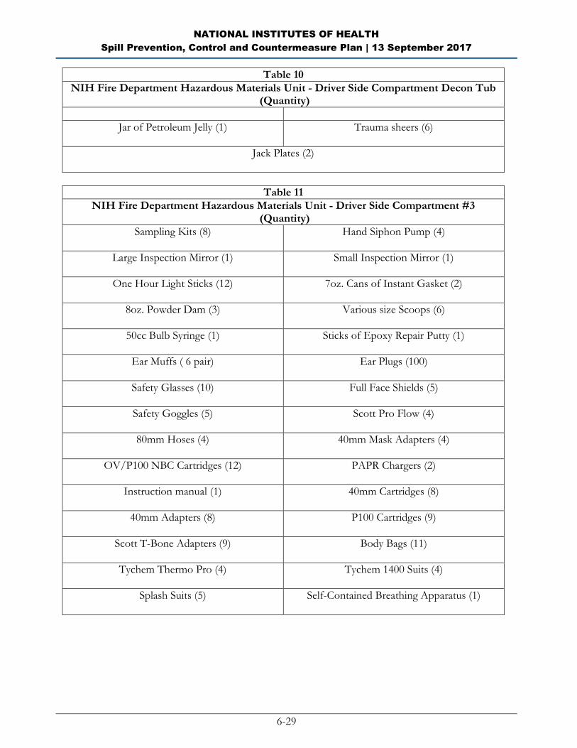
NATIONAL INSTITUTES OF HEALTH
Spill Prevention, Control and Countermeasure Plan | 13 September 2017
6-29
Table 10
NIH Fire Department Hazardous Materials Unit - Driver Side Compartment Decon Tub (Quantity)
Jar of Petroleum Jelly (1)
Trauma sheers (6)
Jack Plates (2)
Table 11
NIH Fire Department Hazardous Materials Unit - Driver Side Compartment #3 (Quantity)
Sampling Kits (8)
Hand Siphon Pump (4)
Large Inspection Mirror (1)
Small Inspection Mirror (1)
One Hour Light Sticks (12)
7oz. Cans of Instant Gasket (2)
8oz. Powder Dam (3)
Various size Scoops (6)
50cc Bulb Syringe (1)
Sticks of Epoxy Repair Putty (1)
Ear Muffs ( 6 pair)
Ear Plugs (100)
Safety Glasses (10)
Full Face Shields (5)
Safety Goggles (5)
Scott Pro Flow (4)
80mm Hoses (4)
40mm Mask Adapters (4)
OV/P100 NBC Cartridges (12)
PAPR Chargers (2)
Instruction manual (1)
40mm Cartridges (8)
40mm Adapters (8)
P100 Cartridges (9)
Scott T-Bone Adapters (9)
Body Bags (11)
Tychem Thermo Pro (4)
Tychem 1400 Suits (4)
Splash Suits (5)
Self-Contained Breathing Apparatus (1)

NATIONAL INSTITUTES OF HEALTH
Spill Prevention, Control and Countermeasure Plan | 13 September 2017
6-30
Table 12
NIH Fire Department Hazardous Materials Unit Driver Side Compartment #4 (D-4)
Type Quantity
Trash Bags (100) Boxes of 6oz Sqwincher Mix (50 packets/box) (3)
Five Gallon Sqwincher Drink Mix Packets (4)
Towels (25)
Blankets (4)
Chlorine “A” Kit (1)
Chlorine “B” Kit (1)
Dome Clamps (4)
Large Tool Box (Various wrenches, sockets, Etc) (1)
Pneumatic Tool Box (1) containing: 3/8” Drill (1)
Reciprocating Saw (1) Air Chisel (1)
Hole Saw Kit (1) Non-Sparking Tool (1)
Edward Cromwell pipe Wrap Kit (1) Edward Cromwell Drum Kit (1)
Edward Cromwell Internal Plug kit (1) Edward Cromwell Large Tank Kit (1)
Drum Kit Box (1) containing: HazGard Neutralizing System (1)
Drum Pumps (2) Short Grounding Cables (2) 10’ Grounding Cables (2)
Drum Hoist (1) Small Hand Pumps (4)
Drum Roll (1) Storm Drain Magnets (7)
Table 13
NIH Fire Department Hazardous Materials Unit - Drivers Side Compartment #5 (D-5) (Quantity)
Stokes Basket with Back Board (1) Portable Breathing Air Hoses (290’ of Hose) (4)
Little Giant Ladder (1)
3500 watt Honda Generator (1)
100’ Fall Protection Winch (1)
100’ Working Winch (1)
Hazmat SKED (2)
Table 14
NIH Fire Department Hazardous Materials Unit - Drivers Side Compartment #6 (D-6) (Quantity)
Type Quantity
300’X1/2” Rope (4) 306’X1/2” Rope (1)
297’X1/2 Rope (1) 150’X1/2” Rope (3)
150’X1/2” Utility Rope (1) Bags of Orange Flags (2)
Class III Harness (8) LSP Harness (1)
SKED Stretcher (1) Edge Protector Roller (2)
Pickets (10) Windless Pickets (5)
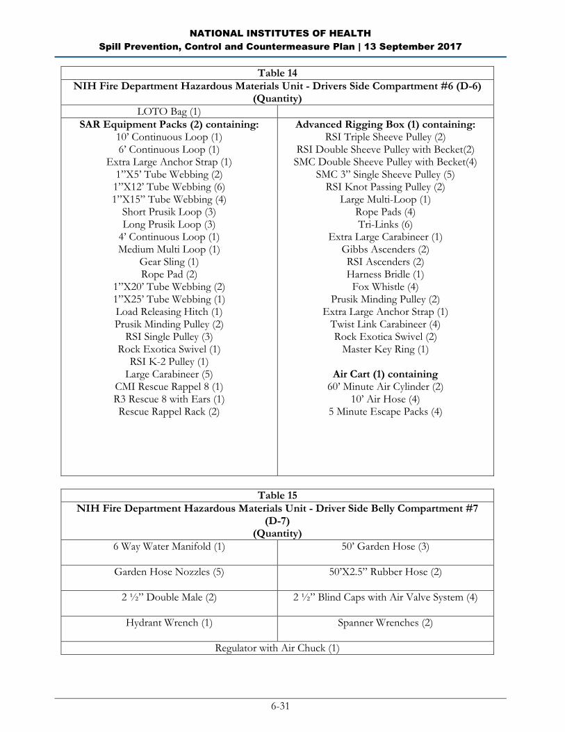
NATIONAL INSTITUTES OF HEALTH
Spill Prevention, Control and Countermeasure Plan | 13 September 2017
6-31
Table 14
NIH Fire Department Hazardous Materials Unit - Drivers Side Compartment #6 (D-6) (Quantity)
LOTO Bag (1)
SAR Equipment Packs (2) containing: 10’ Continuous Loop (1) 6’ Continuous Loop (1)
Extra Large Anchor Strap (1) 1”X5’ Tube Webbing (2) 1”X12’ Tube Webbing (6) 1”X15” Tube Webbing (4)
Short Prusik Loop (3) Long Prusik Loop (3)
4’ Continuous Loop (1) Medium Multi Loop (1)
Gear Sling (1) Rope Pad (2)
1”X20’ Tube Webbing (2) 1”X25’ Tube Webbing (1) Load Releasing Hitch (1) Prusik Minding Pulley (2)
RSI Single Pulley (3) Rock Exotica Swivel (1)
RSI K-2 Pulley (1) Large Carabineer (5)
CMI Rescue Rappel 8 (1) R3 Rescue 8 with Ears (1) Rescue Rappel Rack (2)
Advanced Rigging Box (1) containing: RSI Triple Sheeve Pulley (2)
RSI Double Sheeve Pulley with Becket(2) SMC Double Sheeve Pulley with Becket(4)
SMC 3” Single Sheeve Pulley (5) RSI Knot Passing Pulley (2)
Large Multi-Loop (1) Rope Pads (4) Tri-Links (6)
Extra Large Carabineer (1) Gibbs Ascenders (2) RSI Ascenders (2) Harness Bridle (1)
Fox Whistle (4) Prusik Minding Pulley (2)
Extra Large Anchor Strap (1) Twist Link Carabineer (4) Rock Exotica Swivel (2)
Master Key Ring (1)
Air Cart (1) containing 60’ Minute Air Cylinder (2)
10’ Air Hose (4) 5 Minute Escape Packs (4)
Table 15
NIH Fire Department Hazardous Materials Unit - Driver Side Belly Compartment #7 (D-7)
(Quantity)
6 Way Water Manifold (1)
50’ Garden Hose (3)
Garden Hose Nozzles (5)
50’X2.5” Rubber Hose (2)
2 ½” Double Male (2)
2 ½” Blind Caps with Air Valve System (4)
Hydrant Wrench (1)
Spanner Wrenches (2)
Regulator with Air Chuck (1)
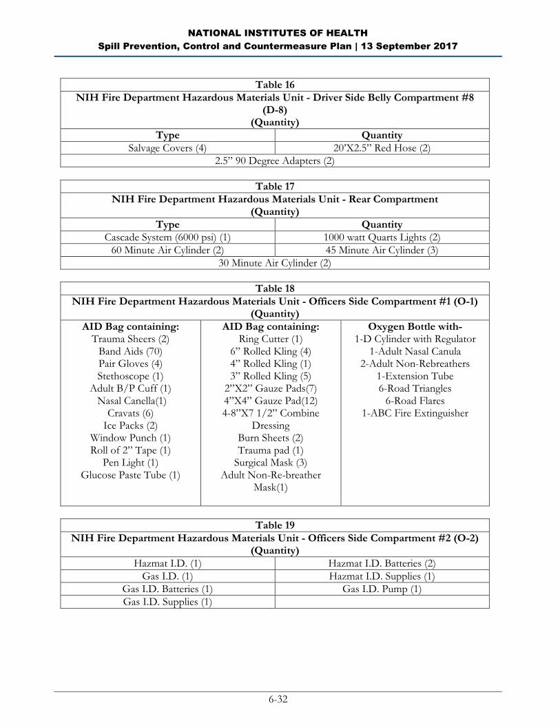
NATIONAL INSTITUTES OF HEALTH
Spill Prevention, Control and Countermeasure Plan | 13 September 2017
6-32
Table 16
NIH Fire Department Hazardous Materials Unit - Driver Side Belly Compartment #8 (D-8)
(Quantity)
Type Quantity
Salvage Covers (4) 20’X2.5” Red Hose (2)
2.5” 90 Degree Adapters (2)
Table 17
NIH Fire Department Hazardous Materials Unit - Rear Compartment (Quantity)
Type Quantity
Cascade System (6000 psi) (1) 1000 watt Quarts Lights (2)
60 Minute Air Cylinder (2) 45 Minute Air Cylinder (3)
30 Minute Air Cylinder (2)
Table 18
NIH Fire Department Hazardous Materials Unit - Officers Side Compartment #1 (O-1) (Quantity)
AID Bag containing: Trauma Sheers (2)
Band Aids (70) Pair Gloves (4) Stethoscope (1)
Adult B/P Cuff (1) Nasal Canella(1)
Cravats (6) Ice Packs (2)
Window Punch (1) Roll of 2” Tape (1)
Pen Light (1) Glucose Paste Tube (1)
AID Bag containing: Ring Cutter (1)
6” Rolled Kling (4) 4” Rolled Kling (1) 3” Rolled Kling (5)
2”X2” Gauze Pads(7) 4”X4” Gauze Pad(12) 4-8”X7 1/2” Combine
Dressing Burn Sheets (2) Trauma pad (1)
Surgical Mask (3) Adult Non-Re-breather
Mask(1)
Oxygen Bottle with- 1-D Cylinder with Regulator
1-Adult Nasal Canula 2-Adult Non-Rebreathers
1-Extension Tube 6-Road Triangles
6-Road Flares 1-ABC Fire Extinguisher
Table 19
NIH Fire Department Hazardous Materials Unit - Officers Side Compartment #2 (O-2) (Quantity)
Hazmat I.D. (1) Hazmat I.D. Batteries (2)
Gas I.D. (1) Hazmat I.D. Supplies (1)
Gas I.D. Batteries (1) Gas I.D. Pump (1)
Gas I.D. Supplies (1)
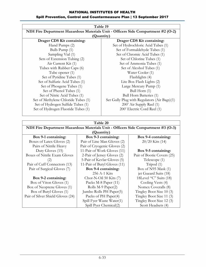
NATIONAL INSTITUTES OF HEALTH
Spill Prevention, Control and Countermeasure Plan | 13 September 2017
6-33
Table 19
NIH Fire Department Hazardous Materials Unit - Officers Side Compartment #2 (O-2) (Quantity)
Drager CDS Kit containing: Hand Pumps (2) Bulb Pump (1)
Sampling Vial (1) Sets of Extension Tubing (2)
Air Current Kit (1) Tubes with Rubber Caps (6)
Tube opener (1) Set of Pyridine Tubes (1)
Set of Sulfuric Acid Tubes (1) Set of Phosgene Tubes (1) Set of Phenol Tubes (1)
Set of Nitric Acid Tubes (1) Set of Methylene Chloride Tubes (1) Set of Hydrogen Sulfide Tubes (1)
Set of Hydrogen Fluoride Tubes (1)
Drager CDS Kit containing: Set of Hydrochloric Acid Tubes (1)
Set of Formaldehyde Tubes (1) Set of Chromic Acid Tubes (1)
Set of Chlorine Tubes (1) Set of Ammonia Tubes (1) Set of Alcohol Tubes (1)
Water Cooler (1) Flashlights (4)
Lite Box Flash Lights (2) Large Mercury Pump (1)
Bull Horn (1) Bull Horn Batteries (1)
Set Gully Plug with Regulators (Air Bags)(1) 200’ Air Supply Reel (1)
200’ Electric Cord Reel (1)
Table 20
NIH Fire Department Hazardous Materials Unit - Officers Side Compartment #3 (O-3) (Quantity)
Box 9-1 containing: Boxes of Latex Gloves (2)
Pairs of Nitrile Heavy Duty Gloves (15)
Boxes of Nitrile Exam Gloves (2)
Pair of Cuff Connectors (13) Pair of Surgical Gloves (7)
Box 9-2 containing:
Box of Viton Gloves (1) Box of Neoprene Gloves (1)
Box of Butyl Gloves (1) Pair of Silver Shield Gloves (24)
Box 9-3 containing: Pair of Line Man Gloves (2) Pair of Cryogenic Gloves (2) 11-Pair of Work Gloves (11) 2-Pair of Jersey Gloves (2) 5-Pair of Kevlar Gloves (5) 11-Pair of Butyl Gloves (11)
Box 9-4 containing: 256 A-1 Kits
Chor-N-Oil 50 Kits (7) Packs M-8 Paper (11) Rolls M-9 Paper(2)
Jumbo Rolls PH Paper(5) Packs of PH Paper(4)
Spill Fyer Waste Water(1) Spill Pyer Chemical(2)
Box 9-4 containing: 20/20 Kits (14)
Box 9-5 containing:
Pair of Bootie Covers (25) Telescope (1)
Tripod (1) Box of N95 Mask (1) jet Gueard Suits (18)
18Level “C” Suits (18) Cooling Vests (4)
Nomex Coveralls (8) Tingley Boot Size 10 (3) Tingley Boot Size 11 (3) Tingley Boot Size 12 (3)
Scott Headsets (4)
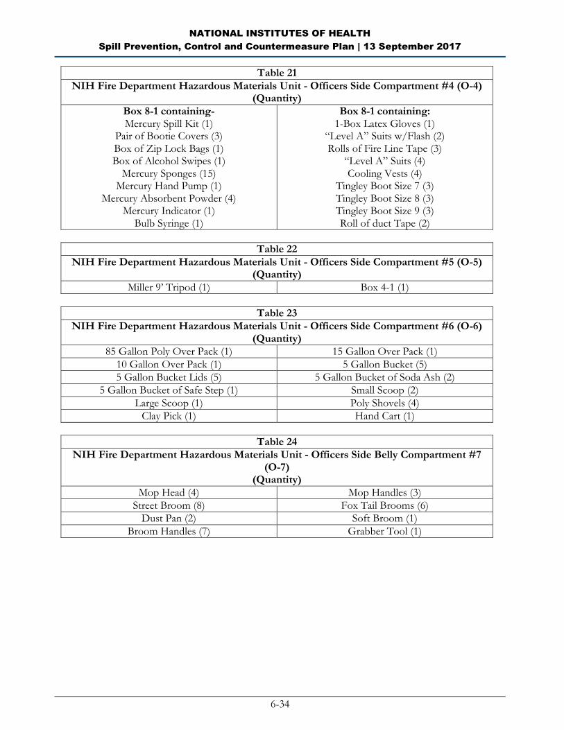
NATIONAL INSTITUTES OF HEALTH
Spill Prevention, Control and Countermeasure Plan | 13 September 2017
6-34
Table 21
NIH Fire Department Hazardous Materials Unit - Officers Side Compartment #4 (O-4) (Quantity)
Box 8-1 containing- Mercury Spill Kit (1)
Pair of Bootie Covers (3) Box of Zip Lock Bags (1) Box of Alcohol Swipes (1)
Mercury Sponges (15) Mercury Hand Pump (1)
Mercury Absorbent Powder (4) Mercury Indicator (1)
Bulb Syringe (1)
Box 8-1 containing: 1-Box Latex Gloves (1)
“Level A” Suits w/Flash (2) Rolls of Fire Line Tape (3)
“Level A” Suits (4) Cooling Vests (4)
Tingley Boot Size 7 (3) Tingley Boot Size 8 (3) Tingley Boot Size 9 (3) Roll of duct Tape (2)
Table 22
NIH Fire Department Hazardous Materials Unit - Officers Side Compartment #5 (O-5) (Quantity)
Miller 9’ Tripod (1) Box 4-1 (1)
Table 23
NIH Fire Department Hazardous Materials Unit - Officers Side Compartment #6 (O-6) (Quantity)
85 Gallon Poly Over Pack (1) 15 Gallon Over Pack (1)
10 Gallon Over Pack (1) 5 Gallon Bucket (5)
5 Gallon Bucket Lids (5) 5 Gallon Bucket of Soda Ash (2)
5 Gallon Bucket of Safe Step (1) Small Scoop (2)
Large Scoop (1) Poly Shovels (4)
Clay Pick (1) Hand Cart (1)
Table 24
NIH Fire Department Hazardous Materials Unit - Officers Side Belly Compartment #7 (O-7)
(Quantity)
Mop Head (4) Mop Handles (3)
Street Broom (8) Fox Tail Brooms (6)
Dust Pan (2) Soft Broom (1)
Broom Handles (7) Grabber Tool (1)
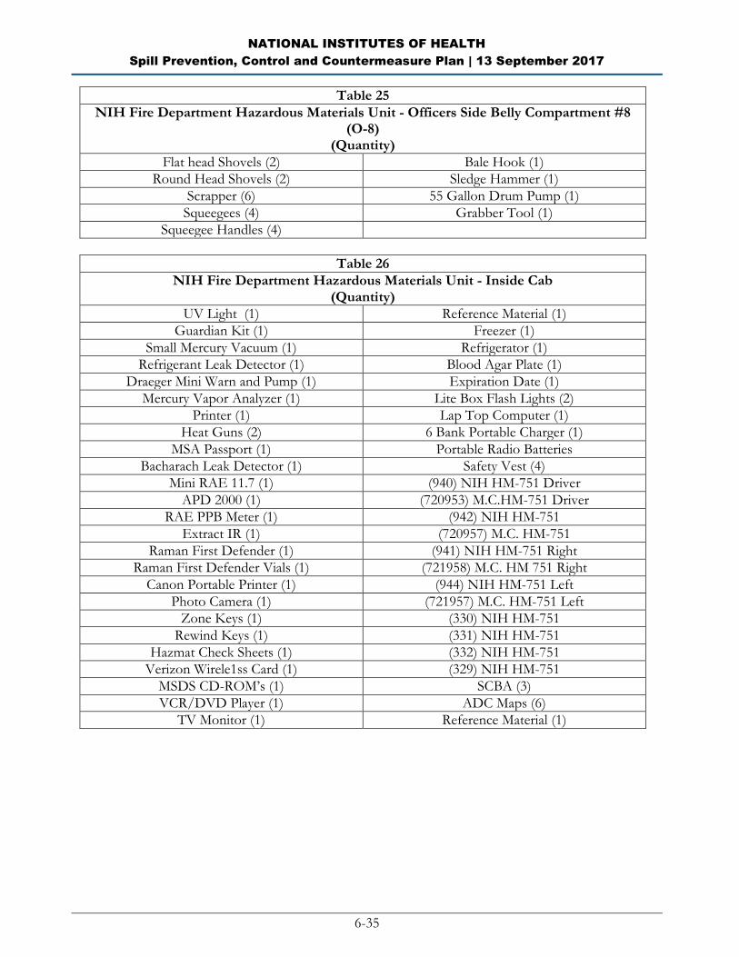
NATIONAL INSTITUTES OF HEALTH
Spill Prevention, Control and Countermeasure Plan | 13 September 2017
6-35
Table 25
NIH Fire Department Hazardous Materials Unit - Officers Side Belly Compartment #8 (O-8)
(Quantity)
Flat head Shovels (2) Bale Hook (1)
Round Head Shovels (2) Sledge Hammer (1)
Scrapper (6) 55 Gallon Drum Pump (1)
Squeegees (4) Grabber Tool (1)
Squeegee Handles (4)
Table 26
NIH Fire Department Hazardous Materials Unit - Inside Cab (Quantity)
UV Light (1) Reference Material (1)
Guardian Kit (1) Freezer (1)
Small Mercury Vacuum (1) Refrigerator (1)
Refrigerant Leak Detector (1) Blood Agar Plate (1)
Draeger Mini Warn and Pump (1) Expiration Date (1)
Mercury Vapor Analyzer (1) Lite Box Flash Lights (2)
Printer (1) Lap Top Computer (1)
Heat Guns (2) 6 Bank Portable Charger (1)
MSA Passport (1) Portable Radio Batteries
Bacharach Leak Detector (1) Safety Vest (4)
Mini RAE 11.7 (1) (940) NIH HM-751 Driver
APD 2000 (1) (720953) M.C.HM-751 Driver
RAE PPB Meter (1) (942) NIH HM-751
Extract IR (1) (720957) M.C. HM-751
Raman First Defender (1) (941) NIH HM-751 Right
Raman First Defender Vials (1) (721958) M.C. HM 751 Right
Canon Portable Printer (1) (944) NIH HM-751 Left
Photo Camera (1) (721957) M.C. HM-751 Left
Zone Keys (1) (330) NIH HM-751
Rewind Keys (1) (331) NIH HM-751
Hazmat Check Sheets (1) (332) NIH HM-751
Verizon Wirele1ss Card (1) (329) NIH HM-751
MSDS CD-ROM’s (1) SCBA (3)
VCR/DVD Player (1) ADC Maps (6)
TV Monitor (1) Reference Material (1)

NATIONAL INSTITUTES OF HEALTH
Spill Prevention, Control and Countermeasure Plan | 13 September 2017
6-36
Table 27
NIH Fire Department Hazardous Materials Unit - Front Off. Side Coffin Comp. #1 (C-1) (Quantity)
Pump Sprayer (2) Transfer Pump Box (1)
Roll Plastic (2) Box of Oil Only Socks (1)
Betts Valve (1) Oil Only Socks (Loose) (13)
Betts Valve Wrench (1) Grounding Rod (1)
Mop Bucket (1) 10’ Pike pole (1)
Mop Ringer (1) Hazmet SKED (1)
Hose Pump (1) Weather Station Head (1)
Table 28
NIH Fire Department Hazardous Materials Unit - Rear Off. Side Coffin Comp. #2 (C-2) (Quantity)
Pack of Oil Only Pads (1) Pig Pillows (10)
Pack of Acid Only Pads (1) Large Oil Only Socks/Booms (5)
Pack of universal (1)
Table 29
NIH Fire Department Hazardous Materials Unit - Middle Coffin Comp. #3 (C-3) (Quantity)
Utility Rope 300’ (Black) (1) 300’X5/8” Rope (Black) (2)
Vouel Lube (1)
Table 30
NIH Fire Department Hazardous Materials Unit - Front Dr. Side Coffin Comp. #1 (C-4) (Quantity)
Saddle Vent (1) Submersible Pump (1)
Drum Thief Box (1) Drum Sampler Box (1)
Hand Pump (1) Drum Cart (1)
Garden Hose (1) Stinger (1)
Decon Shower (1) Decon Pools (4)
Confine Space Ventilator (1) Confine Space Ventilator Hose (1)
Table 31
NIH Fire Department Hazardous Materials Unit - Rear Dr. Side Coffin Comp. #2 (C-5) (Quantity)
Folding Chairs (6) Bundle of Stakes (1)
Stinger Hose Couplers (1) Large Oil Only Socks/Booms (3)
Orange Snow Fence (1) 5 Gallon Bucket Safe Step (1)
Black Snow Fence (1) 5 Gallon Bucket Soda Ash (1)
4’PVC Pipe (4) Adsorbent Level (1)

NATIONAL INSTITUTES OF HEALTH
Spill Prevention, Control and Countermeasure Plan | 13 September 2017
6-37
APPENDIX I: Agency Notification Standard Report
Information contained in this report, and any supporting documentation, must be submitted to the EPA
Region 3 Regional Administrator, and to MDE, within 60 days of the qualifying discharge incident.
Facility: National Institutes of Health Bethesda Campus
Name of person filing report:
Location: 9000 Rockville Pike
Bethesda, MD 20892
Maximum storage capacity: 176,994 gallons
Daily throughput:
Nature of qualifying incident(s):
__ Discharge to navigable waters or adjoining shorelines exceeding 1,000 gallons
__ Second discharge exceeding 42 gallons within a 12-month period.
Description of facility (attach maps, flow diagrams, and topographical maps): The NIH is an Operating Division (OPDIV) of the Department of Health and Human Services (DHHS).
The NIH is the primary federal medical research agency and is tasked with both leading the nation’s
medical research initiatives and providing funding and support to medical institutions across the country.
The NIH is comprised of 27 institutes, each with a specific research agenda, often focusing on particular
disease or body symptoms.
The NIH Bethesda Campus includes a research hospital, patient-family temporary houses, clinics, animal
research, approximately 5,000 labs, office buildings, a power plant that provides steam and electricity to
the NIH Bethesda Campus (Building 11), grounds maintenance area and fuel dispensing area. The NIH
Bethesda Campus is located at 9000 Rockville Pike in Bethesda, Maryland, and spans over 322 acres with
70 buildings and has more than 22,000 employees. Hours of operation are 24 hours per day, seven days
per week. Personnel at the facility with oil handling responsibilities include the DEP Director, DEP staff
managing the fuel storage program and contractor personnel responsible for maintaining, inspecting and
loading tanks.

NATIONAL INSTITUTES OF HEALTH
Spill Prevention, Control and Countermeasure Plan | 13 September 2017
6-38
Agency Notification Standard Report (cont’d)
Cause of the discharge(s), including a failure analysis of the system and subsystems in
which the failure occurred:
Corrective actions and countermeasures taken, including a description of equipment
repairs and replacements:
Additional preventive measures taken or contemplated to minimize possibility of
recurrence:
Other pertinent information:

NATIONAL INSTITUTES OF HEALTH
Spill Prevention, Control and Countermeasure Plan | 13 September 2017
6-39
APPENDIX J: Compliance Plan
As mentioned in this SPCC Plan, some single-walled bulk ASTs do not have adequate secondary containment.
Secondary containment will be provided for these tanks as specified in Table J-1 below:
Table J-1: ASTs without Adequate Secondary Containment
Location Issue Tank Compliance Plan Compliance
Deadline
Building 10 Secondary
containment for
single-wall AST
MDE Tank #6
(100-gallon
emergency
generator sub-
base tank)
NIH will construct a
concrete berm
surrounding the AST to
provide sufficient
secondary containment
NIH will provide
secondary
containment within
90 days of plan
signature
Building 10
(A-Wing)
Secondary
containment for
single-wall AST
MDE Tank #7
(1,000 gallon
emergency
generator sub-
base tank)
NIH will construct a
concrete berm
surrounding the AST to
provide sufficient
secondary containment
NIH will provide
secondary
containment within
90 days of plan
signature
Building 45
(P2AN.04C
Generator
Room)
Secondary
containment for
single-wall AST
MDE Tank #58
(275 gallon
emergency
generator day
tank)
NIH will construct a
concrete berm
surrounding the AST to
provide sufficient
secondary containment
NIH will provide
secondary
containment within
90 days of plan
signature
Building 45
(P2AN.04C
Generator
Room)
Secondary
containment for
single-wall AST
MDE Tank #58
(275 gallon
emergency
generator return
tank)
NIH will construct a
concrete berm
surrounding the AST to
provide sufficient
secondary containment
NIH will provide
secondary
containment within
90 days of plan
signature
NATIONAL INSTITUTES OF HEALTH
Spill Prevention, Control and Countermeasure Plan | 13 September 2017
6-40
BLANK PAGE

NATIONAL INSTITUTES OF HEALTH
Spill Prevention, Control and Countermeasure Plan | 13 September 2017
6-41
APPENDIX K: Incident Reporting Form
Completed by: ____________________________
Title: ____________________________
Date: ____________________________
Instructions: In the event of a spill or other hazardous materials incident, provide the following information to
the NIH SPCC Designated Person.
Facility Name:
Facility Address:
Facility Phone Number:
Date of Incident:
Time Incident Occurred
Type of Material Discharged
Source of the Discharge
Cause of the Discharge
Estimate of the Total
Quantity Discharged
Estimate of the Quantity
Discharged into Navigable
Waters
Estimate of Area/Volume
Soil Affected
Description of Affected
Media
Health Hazards Encountered
Damage or Injuries Caused
by Discharge
Actions Implemented to
Stop, Remove or Mitigate
Effects of the Discharge
Response Time and
Effectiveness
Outside Agencies &
Resources Contacted and/or
Employed
Names of Individuals and/or
Organizations who have
been Contacted
Evacuation Required
Note: Attach photographic documentation, written eye-witness accounts and map of affected area.

NATIONAL INSTITUTES OF HEALTH
Spill Prevention, Control and Countermeasure Plan | 13 September 2017
6-42
BLANK PAGE