nickel alloys and stainless steels for elevated .../media/files/technicalliterature/... · nickel...
TRANSCRIPT
Nickel alloys and stainless steelsfor elevated temperature service:
weldability considerations
Reprinted with permission fromProceedings from Materials Solutions '97 on
Joining and Repair of Gas Turbine ComponentsASM International, September 1997, Indianapolis, Indiana
NiDINICKEL DEVELOPMENT INSTITUTE
NiDI Reprint Series NQ 14 053
D.J. Tillack

The material presented inthis publication has beenprepared for the generalinformation of the readerand should not be used orrelied on for specificapplications without firstsecuring competent advice.
The Nickel DevelopmentInstitute, its members, staffand consultants do notrepresent or warrant itssuitability for any general orspecific use and assume noliability or responsibility ofany kind in connection withthe information herein.

Proceedings from Materials Solutions '97 on Joining and Repair of Gas Turbine Components15 -18 September 1997, Indianapolis, Indiana
Nickel Alloys & Stainless Steels for Elevated Temperature Service:Weldability Considerations
D. J. TillackTillack Metallurgical Consulting, Inc.
Huntington, WV
ABSTRACT:The gas turbine is one of the most demandingapplications for materials, particularly the hot sectionsof the turbine. The welds that join the variouscomponents of the turbine must withstand the samehigh pressures and temperatures. Complicating thisrequirement is the fact that gas turbine materials canbe metallurgically complex and can be a challenge toweld. The actual welding of these materials is notparticularly difficult as long as established guidelinesare followed, but microfissuring and strain-agecracking can be a problem. By being aware of therole of residual elements and the effect of stress onthe weld area, many of these materials can bewelded successfully.
A MODERN GAS TURBINE ENGINE relies heavily onaustenitic materials, primarily nickel-base alloys, towithstand the aggressive conditions encounteredduring operation of the turbine. Not only do thesematerials need to be strong at elevated temperatures,they also need to be able to withstand the corrosiveenvironment of the combustion gas stream. There isalso a need for metallurgical stability and reliability,since these components will be expected to providetrouble-free service for thousands of hours.
While these austenitic materials do possess veryattractive properties, the expected design life of thecomponents fabricated from these alloys can only beachieved if the welds used in their construction are ofsuitable quality. Not only must the design of thecomponents be optimized to resist the stressesimposed during service, but the welds themselvesneed to be deposited and positioned properly toachieve desired results.
There are two main categories of weldassociated defects. The first group include those that
29
occur during the welding operation, such as undercut,porosity, slag inclusions, lack of fusion and insufficientpenetration. These are associated with the weldingprocess but are also influenced by the material beingwelded and the filler metal material. An examplewould be the relatively sluggish nature of a nickel alloyweld puddle, which necessitates opening up of theweld joint to allow proper manipulation of the fillermetal. The second group of weld-associated defectsare metallurgical in nature, such as microfissuring inthe HAl or weld metal. There are times when a welddefect involves both categories, such as the centerlinecracking of a weld which can be part weldingprocedure (improper weld bead contour, for example)and part metallurgical (high levels of deleterious traceelements, for example).
Austenitic Materials Used inGas Turbines
The modern gas turbine engine has madetremendous strides since Sir Frank Whittle developedthe first gas turbine in the late 1930s. Temperatures,pressures and stresses have increased steadily; theseadvancements have been made possible by improveddesign, new alloy developments and advances inmetal processing/fabrication. An example of theinfluence of processing innovations is theimprovements in alloy 718 properties created by triplemelting.
Table 1 lists many of the alloys used in thecompressor, combustor and turbine sections of amodern gas turbine engine. Included are designationsas to whether the alloys are usually used in thewrought or cast condition and whether thecompositions are solid solution or precipitationhardenable.

Table 1a Compositions of precipitation-hardenable nickel and iron alloys for gas turbines
wo
Alloy UNS Composition - Weight %Name No.
Ni Co Cr Fe Mo Nb AI Ti W Zr B Other
706 N09706 42 16 40 2.9 .2 1.8
718 N07718 52 19 3 5.2 .5 .9
X-750 N07750 73 15.5 7 1 .7 2.5
MA754 N07754 78 20 .3 .5 .6 VP3
Re 41 N07041 55 11 19 10 1.5 3.1 .005
Re 95 61 8 14 3.5 3.5 2.5 3.5 .05 .010 .15C
U-500 N07500 54 18 18 4 2.9 2.9 .05 .006
U-700 53 18.5 15 5.2 4.3 3.5 .030
Waspaloy N07001 58 13.5 19.5 4.3 1.3 3 .06 .006
214 N07214 75 16 3 4.5 .1- .01-
N-155 R30155 20 20 21 30 3 1 .8 2.5 1.5Mn•.15N
80A N07080 76 19.5 1.4 2.4 .06 .003
90 N07090 59 16.5 19.5 1.4 2.4 .06 .005
105 53 20 15 5 4.7 1.2 .10 .005
115 60 13 14 3.3 4.9 3.7 .04 .160
Discaloy K66220 26 14 54 2.7 .1 1.7 .005 .9Mn•.8Si
901 N09901 43 12 36 6 .2 2.8 .015
903 N19903 38 15 41 3 .7 1.4
909 N19909 38 13 42 4.7 1.5 .001 .4Si
783 R30783 29 34 3 26 3 5.4 .1
A-286 S66286 26 15 54 1.3 .2 2 .015 1.3Mn..5Si
17-4PH S17400 4 17 75 .3 4Cu
\Iote: all cart on levels are U.1 UUfo or below_urlless otherwise noted - maximum

Table 1b Compositions of wrought solid solution nickel, cobalt, and iron alloys for gas turbines
Alloy UNS Composition - Weight %Name No.
Ni Co Cr Fe Mo Nb AI Ti W 8 Other
Hast. 8 N06635 67 16 1 15 .3 .02La
Hast. X N06002 47 1.5 22 18 9 2 .6
230 N06230 57 5' 22 2 .3 14 .005 .48i, .02La
242 65 8 25
556 R30556 21 20 22 29 3 .1 .3 2.5 .5Ta, .02La
600 No6600 76 15.5 8
601 N06601 61 23 14 1.3
617 N06617 55 12.5 22 9 1
625 N06625 61 21.5 2 9 3.6 .2 .2
L-605 R30605 10 51 20 15 1.5Mn
188 R30188 22 40 22 14 .03La
75 N06075 75 20 5 .4
263 N07263 51 20 20 6 .4 2 .13C
HR-120 N08120 37 25 33 .7 .004 .2N
HR-160 N12160 37 29 28 2 2.758i
800H N08810 33 21 46 .4 .4 .8Mn
330 N08330 35 19 45 1.28i
803 865803 35 27 37 .3 .4
Note: all carbon levels are 0.10% or below, unless otherwise noted , = maximum
Table 1c Compositions of cast polycrystalline nickel and cobalt alloys for gas turbines
I Alloy ~Cr~ 8 IC I Other IIN-100 64 15 10 3 5.5 4.7 .06 .014 .18 1V
IN-713 75 12 4.5 5.9 .6 .10 .010 .12 2Nb
IN-738 62 8.5 16 1.8 3.4 3.4 2.6 .10 .010 .17 1.8Ta..9Nb
IN-792 61 9 13 2 3.2 4.2 3.9 .10 .020 .21 3.9Ta
IN-939 49 19 22 1.9 3.7 2 .10 .009 .15 1.4Ta. 1Nb
8-1900 65 10 8 6 6 1 .08 .015 .10 4.3Ta
X-40 10 56 25 8 .010 .50
FSX-414 10 53 29 7 .010 .25
MAR-M 247 60 10 8 .6 5.5 1 10 .09 .020 .16 3Ta. 1.5Hf
MAR-M 509 10 49 24 .2 7 .60 7.5Ta
31

Making the Weld
The shape and contour of the weld beadsthemselves can be instrumental in whether or not theweld will be crack free. Even if the welds are properlymade, residual stresses from the welding operationmay cause problems, such as distortion or cracking.The effect of welding on the base material is anotherpotential source of problems, particularly with themetallurgically complex alloys that are often specifiedin gas turbines. Post-weld annealing or stressrelieving practices are another potential source forproblems.
The welding process that is used the most injoining gas turbine components is the Gas TungstenArc process, or GTAW. This welding process allowsgreater control of the heat input and provides theability to use very low heat input, which is oftennecessary when joining many of the more difficult-toweld turbine alloys. Also, this process uses bare wireas the filler metal, which avoids slag-related problemsassociated with flux coated electrodes used in theShielded Metal Arc process (SMAW). Another reasonfor the limited use of the SMAW process is thedifficulty of transferring reactive elements, such as AIand Ti, across the arc of a flux-shielded electrode.Many of the nickel alloys used in a gas turbine rely oneither AI or Ti, or both, to achieve their high strengthlevels via precipitation-hardening. The SMAW processis used to weld the solid solution nickel and stainlessalloys, particularly on industrial gas turbine structuralcomponents.
The spray transfer mode of the Gas Metal Arcprocess, or GMAW, is seldom used for weldingcomponents used in a gas turbine because of the highheat input inherent in the process. The crackingproblems that often occur when this process is usedon the metallurgically complex alloys used in a gasturbine do not justify the attractive deposition ratespossible. Limited use of the pulsed mode of GMAWtransfer is found. The electron beam, or EBW,process is also used to a limited extent and is anattractive method because of high production rates,ability to make narrow, deep-penetration welds, and alower heat input per unit length for a given depth ofpenetration. However, there have been HAlmicrofissuring problems with high strength alloys, suchas alloy 718, when using the EBW process,particUlarly with coarse grain material. Table 2compares the effect of grain size on several weldingprocesses (1). This table does not take intoconsideration the thickness of the parts being joinednor the effect of stress on cracking tendency. A highlyrestrained joint, such as with plate material, will bemore sensitive to cracking than thin sheet, if bothmaterials have the same large grain size.
32
Table 2. Effect of grain size on recommendedwelding processesB
Gas Gas ShieldedGrain Metal Electron Tungsten Metal
Alloy Sizeb Arec Beam Arc Arc600 Fine X X X X
Coarse X X617 Fine X X X X
Coarse X625 Fine X X X X
Coarse X X706 Fine X X X
Coarse X71B Fine X X X
Coarse XBOO Fine X X X X
Coarse X X XAISI Type 316 Steel Fine X X X X
Coarse X XAISI Type 347 Steel Fine X X X X
Coarse X X
a. Processes marked Xare recommended.
b. Fine grain is smaller than ASTM Number 5; coarse grain is ASTMNumber 5or larger.
c. Spray transfer.
Susceptibility to weld cracking in austeniticstainless steels and nickel alloys is very dependant onthe shape of the weld pool, which in turn is dependanton the welding process and technique. In general,high heat inputs are more conducive to solidificationcracking but the shape of the weld pool is also veryimportant. A tear-drop shaped weld pool, which isusually associated with automated welding, is moreprone to solidification cracking because of theorientation of the solidifying grains. Figure 1 illustratesthe difference between an undesirable tear-dropshaped weld pool and a desirable elliptical shapedweld pool (2). The solidification pattern of the teardrop shaped weld pool results in centerlinesegregation that may be high in low melting pointelements that will be deleterious to weld hot strength.On the other hand, the elliptical pool shape will havea much greater distribution of these elements, thusminimizing their effect.
The welding process and welding conditionsdetermine the shape of the weld pool, with highertravel speeds and higher heat inputs favoring theundesirable tear-drop shape weld pool. Accordingly,the GMAW and GTAW welding processes will morelikely produce the tear-drop shape weld pool while theSMAW process will usually produce the favored

Table 3 Probable weld pool shape for different welding conditions
Condition Process Consumable Voltage Current Travel Heat Probable PoolDiameter, mm V A Speed, Input Shape
mm/mln kJ/mm
1 SMA 3.2 20 100 180 0.7 Elliptical
2 SMA 4.0 21 145 130 1.4 Elliptical
3 GMA (spray) 1.2 31 320 450 1.3 Teardrop
4 GMA (spray) 1.2 27 240 230 1.7 Elliptical
5 GMA (globular dip) 1.2 23 180 125 2.0 Elliptical
6 Submerged-Arc 2.4 28 270 250 1.8 Elliptical
7 Submerged-Arc 2.4 32 370 620 1.1 Teardrop
-Tear-shape weld pool: growth of columnar grainsresult in high solute centerline segregation concentration
-Elliptical weld pool: more favorable orientation ofgrains, with less concentration of centerline solutesegregation
Fig. 1 Effect of pool shape on solidification structure(arrows indicate welding direction)
elliptically-shaped weld pool. Table 3 lists sever~1
welding processes with varying parameters and theireffect on pool shape. Travel speed stands out as avery influential parameter in controlling pool shape - insome cases, a higher heat input produces the morefavorable elliptical pool shape when combined with
33
lower travel speed. One factor not taken intoconsideration in this comparison is the effect of stress:some austenitic alloys are routinely autogenouslywelded at very high travel speeds that produce teardrop shape weld pools, such as in automatic weldingof alloy 800 (N08800) strip in the production of heaterelement strip for electric ranges. Assisting in thisoperation is the addition of compressive stressesprovided by the forming rolls used to form the stripinto the tubular shape immediately prior to welding.However, most welding operations do not benefit fromsuch compressive stresses. Usually, the strongresidual tensile stresses created during weldingoperations will cause cracking along the centerlinecondition formed in the tear-drop shaped weld pool.
One study of welding parameters and crackingresistance compared welding current with weldingspeed for the autogenous GTAW welding of austeniticstainless steels in sheet form. Cracks were found atlow speeds and cracking became more pronounced asthe speed was increased. At medium speeds theywere replaced by center cavities. The tendency forcrack and center cavity formation increased with sulfurcontent, with these defects being infrequent when thesulfur content was below 0.003%. A reduction in thephosphorous level resulted in fewer cracks but did notgreatly affect center cavity formation. At lower weldingspeeds the weld puddle is elliptical and cracking isdiminished, but when the welding speed is increasedthe puddle becomes tear-drop shaped; in these testson 2mm (0.079 in.) austenitic stainless steel sheetsthis transformation occurred at a speed of about 200mmlmin (7.9 in.lmin) (4). Heavier sections would beable to withstand faster weld travel speeds before theweld pool transforms to tear-drop shape because ofmore favorable heat transfer characteristics.
In addition to the two-dimensional shape of theweld pool during welding, the cross-sectional contourof the weld needs to be convex to providereinforcement during solidification. Concave weldbeads may crack even though they have been weldedwith the desired elliptically shaped weld pool. Foroptimum results, the weld pool shape should beelliptical, or rounded, at the trailing edge, and the weldcontour should be convex.
Problems Associated with Welding
Most gas turbine components need to be weldedsometime during their service life. If welding is notrequired during initial construction of the turbine (suchas single crystal blading) they often need to be repairwelded to extend their service life. Following is adiscussion of several commonly-encountered weldrelated problems.
Weld-associated cracking can be categorized bylocation or time of occurrence. Cracking usuallyoccurs in the weld or HAl:
-during welding-during postweld heat treating-during service.
Cracking during welding usually can be attributed toincorrect welding procedures, such as improperwelding parameters or travel speed. When weldingdissimilar metals, dilution problems that causemetallurgically crack-prone compositions can be asource of cracking.
Hot Cracking Hot cracking, which is also calledsolidification cracking, liquation cracking, fissuring, ormicrofissuring can be controlled in fully austeniticmaterials by paying attention to welding parameters(such as preheat, heat input, travel speed, etc.), jointdesign, joint restraint control and welding technique.There are numerous theories regarding the cause ofhot cracking. One theory is that cracking usuallyoccurs when liquid films are present betweensolidifying grains such that the weld cannotaccommodate the strains caused by cooling (5).These liquid films are heavily influenced by traceelements in the base material or filler metal.Solidification cracking may be caused by segregationor by the formation of second phase films, which arebulk phases formed when the local impurity content isabove the solubility limit. Films are particularlydetrimental because they usually have lower inherentductility than the surrounding region and they replacea single interface (the grain boundary) with twointerphase boundaries that have lower interfacialtension or bonding (6). Other theories include: liquidgrain boundary films due to the melting of
34
intergranular precipitates, such as carbides; solid statedeformation concentrated in the grain boundaries suchas grain boundary sliding; constitutional liquation ofsulfide inclusions; eutectic melting of the grainboundaries due to elements such as sulfur; and theeffect of liquid-solid surface tension on grain boundarywetting (7).
A fusion weld is made by moving a very intenseheat source along the material to be welded. In theimmediate vicinity of the are, the base metal is beingheated rapidly. Expansion of this material isconstrained by the cooler surrounding base materialand the resulting compressive stress causes the HAlto be upset. As the arc passes and the base materialand fusion weld area cools and attempts to contract,it is again constrained. This results in residual tensilestresses. The magnitude of stress can be affected tosome degree by the choice of welding process andheat input; however the thermal stresses cannot beeliminated.
One study (8) on the effect of microfissures onmechanical properties found that microfissures up to0.070" in length had little or no effect on the fatiguestrength of alloy 600 (N06600) weldments. No effectswere noted until the fissures exceeded 5% of thecross-section. Work with alloy 617 (N06617) agreeswith these data; little effect was seen withmicrofissures up to 0.030" in length. This isencouraging since most of the microfissuresencountered are less than 0.015" in length. Onereason for the minimal effect of microfissures is theexcellent ductility and toughness of high nickel alloys.These results suggest that microfissures, althoughcertainly undesirable, are not particularly detrimentalunless they occupy a significant amount of the crosssection.
In addition to Sand P, other elements known toadversely affect hot cracking resistance in nickel alloysare Si and B. Silicon is sometimes added to hightemperature alloys to enhance oxidation andcarburization resistance and for improved castability incast alloys, but it has decidedly deleterious affects onweldability. Nb was first used in Ni-Cr-Fe weld fillermetals many years ago to counter the influence ofsilicon on hot-cracking (9). Crack-free welds wereobtained when the Nb/Si ratio for an alloy 600(N06600) weld composition was 4.5. The criticalNb/Si ratio required to prevent cracking is not thesame for all alloys, but generally tends to increase atconstant Cr level, as the Ni content of the alloy isdecreased. The improved melting techniquesavailable today have enabled metallurgists to lowerthe levels of numerous deleterious elements thatcontribute to weld metal and base metal cracking.
Creq = (%Cr) + (%Mo) + 1.5(%Si) + 0.4(%Nb)Nieq = (%Ni) + 30(%C) + 0.5(%Mn)
techniques and therefore in some respects are not asdangerous as service-related cracks, which are oftennot discovered until failure occurs.
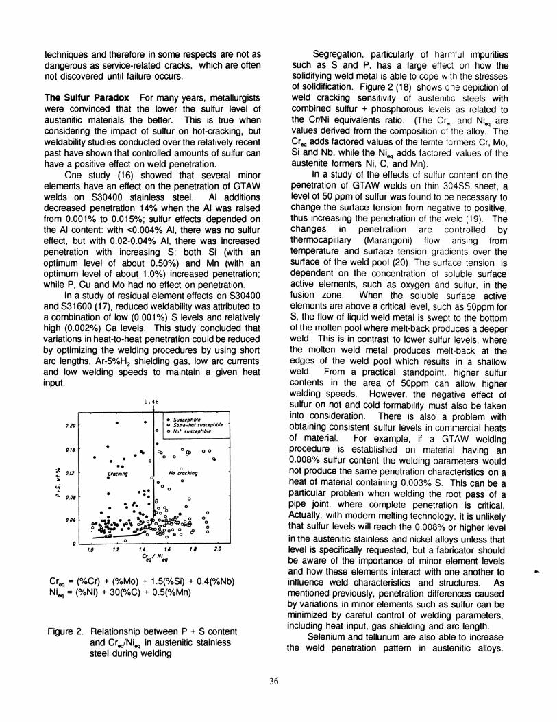
Figure 2. Relationship between P + S contentand Cre/Nieq in austenitic stainlesssteel during welding
The Sulfur Paradox For many years, metallurgistswere convinced that the lower the sulfur level ofaustenitic materials the better. This is true whenconsidering the impact of sulfur on hot-eracking, butweldability studies conducted over the relatively recentpast have shown that controlled amounts of sulfur canhave a positive effect on weld penetration.
One study (16) showed that several minorelements have an effect on the penetration of GTAWwelds on S30400 stainless steel. AI additionsdecreased penetration 14% when the AI was raisedfrom 0.001 % to 0.015%; sulfur effects depended onthe AI content: with <0.004% AI, there was no sulfureffect, but with 0.02-0.04% AI, there was increasedpenetration with increasing S; both Si (with anoptimum level of about 0.50%) and Mn (with anoptimum level of about 1.0%) increased penetration;while P, Cu and Mo had no effect on penetration.
In a study of residual element effects on S30400and S31600 (17), reduced weldability was attributed toa combination of low (0.001%) S levels and relativelyhigh (0.002%) Ca levels. This study concluded thatvariations in heat-to-heat penetration could be reducedby optimizing the welding procedures by using shortarc lengths, Ar-5%H2 shielding gas, low arc currentsand low welding speeds to maintain a given heatinput.
segregation, particularly of harrnfu I impuritiessuch as Sand P, has a large effect on how thesolidifying weld metal is able to cope wrth the stressesof solidification. Figure 2 (18) shows one depiction ofweld cracking sensitivity of austenrtlC steels withcombined sulfur + phosphorous leveis as related tothe Cr/Ni equivalents ratio. (The Cr and Ni are"" eqvalues derived from the composition of the alloy. TheCreq adds factored values of the ferrrte formers Cr, Mo,Si and Nb, while the Nieq adds factored values of theaustenite formers Ni, C, and Mn).
In a study of the effects of su~ur content on thepenetration of GTAW welds on thin 304SS sheet, alevel of 50 ppm of sulfur was found to be necessary tochange the surface tension from negative to positive,thus increasing the penetration of the weld (19). Thechanges in penetration are controlled bythermocapillary (Marangoni) flow arising fromtemperature and surface tension gradients over thesurface of the weld pool (20). The surface tension isdependent on the concentration of soluble surfaceactive elements, such as oxygen and sulfur, in thefusion zone. When the soluble surface activeelements are above a critical level, such as 50ppm forS, the flow of liquid weld metal is swept to the bottomof the molten pool where melt-back produces a deeperweld. This is in contrast to lower sulfur levels, wherethe molten weld metal produces melt-back at theedges of the weld pool which results in a shallowweld. From a practical standpoint, higher sulfurcontents in the area of 50ppm can allow higherwelding speeds. However, the negative effect ofsulfur on hot and cold formability must also be takeninto consideration. There is also a problem withobtaining consistent sulfur levels in commercial heatsof material. For example, if a GTAW weldingprocedure is established on material having an0.008% sulfur content the welding parameters wouldnot produce the same penetration characteristics on aheat of material containing 0.003% S. This can be aparticular problem when welding the root pass of apipe joint, where complete penetration is critical.Actually, with modern melting technology, it is unlikelythat sulfur levels will reach the 0.008% or higher levelin the austenitic stainless and nickel alloys unless thatlevel is specifically requested, but a fabricator shouldbe aware of the importance of minor element levelsand how these elements interact with one another toinfluence weld characteristics and structures. Asmentioned previOUSly, penetration differences causedby variations in minor elements such as sulfur can beminimized by careful control of welding parameters,including heat input, gas shielding and arc length.
Selenium and tellurium are also able to increasethe weld penetration pattem in austenitic alloys.
1.0/./1/.4 /.6
C'«II Hi,,!
1. 48
/.2/.0
. . • Suscophbl•• Som~~hat susc~ptibl... o Not susuptlb'~
. •"It q, 08> 00
• . 0 0. .0
Q..0
Iracking0
No cracking.. ..0
0...• ..e 0
.. I. •• 00 0. ... po~ .. 0.- ... ~ o~oO 0
...~."- ..... rP o ~C8 0
o ~ •• g ~800 0 B0
. .. . 0
___ 0
o .. 0
0
010
0./6
"$. 0./2~.,,-.... 0.0/1
0.04
0
36
Additions of 40, 55, and 140ppm of sa were added toa 21 Cr-6Ni-9Mn austenitic stainless steel and theresulting electron beam weld penetration increased81 %, 158% and 165% respectively (normal sa levelsin the alloy were <20ppm). The sulfur analysis of thethree tests were 34, 29, and 30ppm. When Te wasadded to the same 21-6-9 stainless steel basecomposition, there also was a large increase in weldpenetration: when 43 and 62ppm of Te were added,the weld penetration increased 81 % and 156%respectively (normal Te levels in the alloy were<5ppm). Oxygen has also been shown to increaseweld penetration(21).
A common thread in this discussion of effects ofminor elements on weld penetration is that theelements that increase weld penetration are Group 6Aelements - 0, S, Se, and Te. It would be interestingto see if the other Group 6A element, polonium, alsohas the same effect.
While slight increases in sulfur content may assistin weld penetration in an austenitic solid solutionstainless steel, such as 316, it may not be advisableto use such an approach to improve weld penetrationon a precipitation-hardenable alloy such as alloy 718.Sulfur segregation to grain boundaries in wrought alloy718 has been cited as the cause of HAlmicrocracking (22).
Increased penetration during GTAW welding canalso be achieved by adding small amounts (less than5%) of H to the shielding gas (23). Increases inpenetration of over 50% are possible with H additionsto argon shielding gas.
Strain-Age Cracking Cracking that occurs after aweld has been completed has been called variousnames, including relaxation cracking, postweld heattreatment cracking and strain-age cracking. It isusually associated with precipitation-hardenable alloysand the cracking normally is located in the HAl.Alloys differ greatly in their ability to resist this type ofcracking, with alloy 718 being quite resistant. Thissingle characteristic - of being able to be welded andheat treated without experiencing strain-age cracking is a primary reason for its phenomenal success as agas turbine material. (Approximately 35% of the totalweight of a typical aero gas turbine consists of alloy718.) The crack resistance of the alloy 718 HAl arisesfrom a combination of its relatively sluggishprecipitation-hardening response, and lower strengthand higher ductility at the start of aging compared tosimilar alloys, such as Waspaloy. This permits morerapid relaxation of stresses and crack-freeaccommodation of larger resulting strains. Thestresses which produce the heat-treatment crackingresult from residual welding stresses plus thermally
37
induced stresses generated by differential thermalexpansion in the weldment during heat treatment.Additional stresses also are generated by thedimensional changes caused by precipitation duringpostweld heat treatment. Restraint during weldingimposes stresses which can be exceedingly large (24).
Strain-age cracking is very similar to stressrupture fracture, and can actually be considered to bea very short-term stress-rupture failure. As carbidesand hardeners precipitate, they generate large localmicrostresses due to coherency, lattice mismatch, orshrinkage. The problem can be viewed in terms ofrelaxation or stress relief. If the rate of relaxation israpid in relation to the rate of strength change, stressrelief occurs and there is no strain-age cracking.Relaxation may occur either through diffusion (creep),or by plastic flow (shear). Relaxation is retarded,however, by the strengthening produced by aging.Stress relief also occurs if the elastic modulus dropsrapidly with temperature because the magnitude of theresidual stress is proportional to the elastic modulus.Unfortunately, the elastic moduli of precipitationhardenable, nickel-base alloys do not decrease rapidlywith temperature. The rate of precipitation also playsan important part in strain-age susceptibility. Initially,during welding, the more-rapidly hardening alloys agein the HAls and so there is a concurrent increase inthe yield strength and hence in the maximum possibleresidual stress. During postweld stress-relievingoperations, additional aging takes place and theresultant strengthening of the grains inhibits relaxation,or stress relief (25). To minimize the possibility ofstrain-age cracking in those alloys that precipitationharden rapidly, such as Waspaloy, the material shouldbe in the annealed condition prior to welding or repairwelding and again annealed after welding has beencompleted. If these materials are not annealed afterwelding they will usually crack during the precipitationhardening thermal cycle. Alloys that undergo arelatively sluggish precipitation response, such as alloy718, are quite resistant to strain-age cracking, asmentioned previously, and can often be welded/repairwelded and then directly aged without receiving anintermediate anneal.
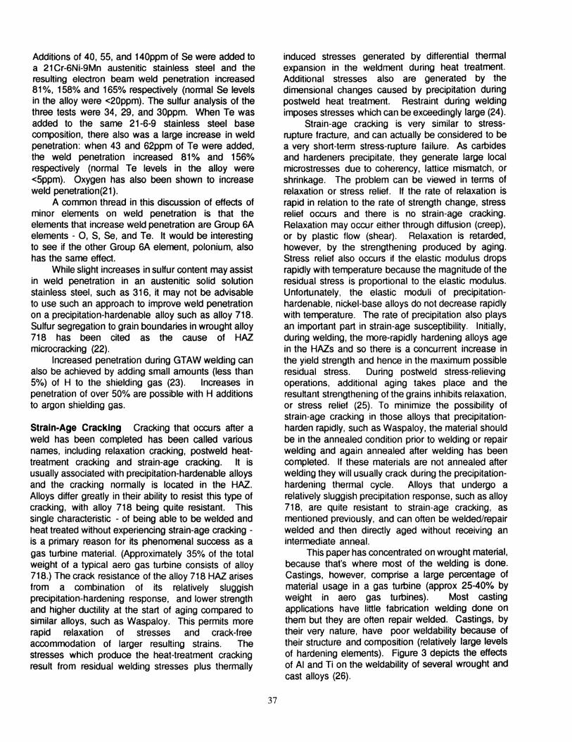
This paper has concentrated on wrought material,because that's where most of the welding is done.Castings, however, comprise a large percentage ofmaterial usage in a gas turbine (approx 25-40% byweight in aero gas turbines). Most castingapplications have little fabrication welding done onthem but they are often repair welded. Castings, bytheir very nature, have poor weldability because oftheir structure and composition (relatively large levelsof hardening elements). Figure 3 depicts the effectsof AI and Ti on the weldability of several wrought andcast alloys (26).
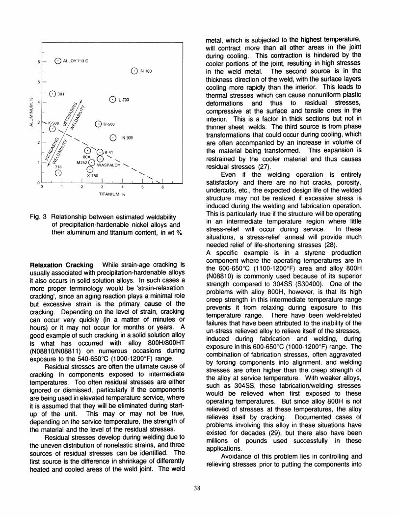
5 -
6 0 ALLOY 713 C
o IN 100
Fig. 3 Relatio~s.hip between estimated weldabilityof ~reclplt~tlon-hardenable nickel alloys andtheir aluminum and titanium content, in wt %
metal, which is subjected to the highest temperature,will contract more than all other areas in the jointduring cooling. This contraction is hindered by thecooler portions of the joint, resulting in high stressesin the weld metal. The second source is in thethickness direction of the weld, with the surface layerscooling more rapidly than the interior. This leads tothermal stresses which can cause nonuniform plasticdeformations and thus to residual stresses,compressive at the surface and tensile ones in theinterior. This is a factor in thick sections but not inthinner sheet welds. The third source is from phasetransformations that could occur during cooling, whichare often accompanied by an increase in volume ofthe material being transformed. This expansion isrestrained by the cooler material and thus causesresidual stresses (27).
. Even if the welding operation is entirelysatisfactory and there are no hot cracks, porosity,undercuts, etc., the expected design life of the weldedstructure may not be realized if excessive stress isin~u~ du.ring the welding and fabrication operation.!hls IS particularly true if the structure will be operatingIn an Intermediate temperature region where littlestress-relief will occur during service. In thesesituations, a stress-relief anneal will provide muchneeded relief of life-shortening stresses (28).A specific example is in a styrene productioncomponent where the operating temperatures are inthe 600-650°C (1100-1200°F) area and alloy 800H(N08810) is commonly used because of its superiorstrength compared to 30455 (530400). One of theproblems with alloy 800H, however, is that its highcreep strength in this intermediate temperature rangeprevents it from relaxing during exposure to thistemperature range. There have been weld-relatedfailures that have been attributed to the inability of theun-stress relieved alloy to relieve itself of the stressesinduced during fabrication and welding, duringexpo~ure. in this 600-650°C (1 000-1200°F) range. Thecombination of fabrication stresses, often aggravatedby forCing components into alignment, and weldingstresses are often higher than the creep strength ofthe alloy at service temperature. With weaker alloys,such as 30455, these fabricationlwelding stresseswould be relieved when first exposed to theseoperating temperatures. But since alloy 800H is notrel~eved ~f stresses at these temperatures, the alloyrelieves Itself by cracking. Documented cases ofproblems involving this alloy in these situations haveexisted for decades (29), but there also have beenmillions of pounds used successfully in theseapplications.
. ~voidance of this problem lies in controlling andrelieVing stresses prior to putting the components into
o IN 939
o U700
o U500
0 301
oeft
~"f ~
8" 0"K500 if 4:0, S,!! <- '(;j..... ...........
S <ff 0'() 0" 8R
-41
i'!' 4: 80A. ,
S M2520 '718 0 WASPALOY ,
O. ,
• X-750 ' ,oO~..L-~----L--::--..L..-..----:----L---l4_.L-l---L:::",l6-J-.!
TITANIUM. %
Relaxation Cracking While strain-age cracking is~sually associated with precipitation-hardenable alloysIt also occurs in solid solution alloys. In such cases amore proper terminology would be 'strain-relaxationcracking', since an aging reaction plays a minimal rolebut excessive strain is the primary cause of thecracking. Depending on the level of strain, crackingcan occur very quickly (in a matter of minutes orhours) or it may not occur for months or years. Agood example of such cracking in a solid solution alloyis what has occurred with alloy 800H/800HT(N0881 0/N08811) on numerous occasions duringexposure to the 540-650°C (1000-1200°F) range.
Residual stresses are often the ultimate cause ofcracking in components exposed to intermediatetemperatures. Too often residual stresses are eitherignored or dismissed, particularly if the componentsare being used in elevated temperature service, whereit is assumed that they will be eliminated during startup of the unit. This mayor may not be true,depending on the service temperature, the strength ofthe material and the level of the residual stresses.
Residual stresses develop during welding due tothe uneven distribution of nonelastic strains, and threesources of residual stresses can be identified. Thefirst source is the difference in shrinkage of differentlyheated and cooled areas of the weld joint. The weld
:;;" 4
::JZ
~
:3 3«
38

service. Parts should not be forced into alignment orotherwise mis-handled. After welding, stress relievingor annealing should be performed. Stress relievingcan be done at 900°C (1650°F) for an hour, with rapidheat-up and cool-down. There should be a minimumof time spent in the carbide precipitation range of 540815°C (1 000-1500°F) to avoid the precipitation of finecarbides (30). Carbides are inevitable in alloyscontaining chromium and carbon, but their morphologyis critical. Carbide films are to be avoided because oftheir propensity for crack initiation and propagation.The optimum morphology for carbides in materialexposed to intermediate temperatures is large anddiscrete.
Annealing to remove fabrication stresses in alloysused in the creep range can cause degradation increep and rupture strength unless proper evaluation ofthe microstructure is performed to assure suitability forelevated temperature service. Solid solution alloysused in high temperature applications are often givena high temperature solution anneal at the mill, whichprovides a large grain size conducive to optimumcreep/rupture strength. If the alloy is given a fairlylarge amount of cold straining during fabrication, ananneal can cause recrystallization and the resultingfine grain size can cause a large reduction in rupturestrength. For example, 10% cold work, in the form ofbending, will result in a recrystallization temperature ofabout 940°C (1750°F) for alloy 800H (N08810) (31).If material in this condition is annealed at 980°C(1800°F), recrystallization will occur in the cold workedarea without grain growth, resulting in greatly reducedrupture strength. In this scenario, the material wouldneed to be solution annealed in the 1150°C (2100°F)area to assure sufficient grain growth in order toachieve the expected design strength. However, onsite annealing is difficult and often impossible.Therefore, fabrication sequences should be properlyplanned to allow for adequate postweld heattreatments.
Conclusions
The austenitic stainless steels and nickel alloys offeradvantages of strength and environmental resistancein high temperature applications. To achieve designlife, weldability of the material must be understood andoptimized. The design of weldments needs to takeinto consideration the sluggish nature of the moltenaustenitic weld metal and the lower weld penetrationcompared to ferritic materials. The welding operationmust be controlled to minimize weld cracking: anelliptical, or rounded, weld puddle trailing edge willminimize centerline segregation; and a convex beadprofile will minimize centerline cracking that can occur
39
with a concave profile. Weld penetration can beinfluenced by trace element variations. Sulfur, inparticular, can dramatically increase weld penetrationin austenitic alloys if present in quantities exceeding50ppm. Precipitation-hardenable alloys are aparticular challenge because of the intermediatetemperature transformations that occur during weldingand heat treating. Microfissuring, which usually occursin the HAZ, is promoted by large grain sizes and highheat input during welding. Strain-age cracking usuallyoccurs during heat treatment and is influenced by alloychemistry and precipitation reaction time. In all weldor HAZ cracking situations, stress plays a dominantrole. Whether the material is solid solution orprecipitation-hardenable, stress cannot be eliminatedduring welding. However, it must be minimized ifcrack-free, long-life weldments are to be realized.
References
1 AWS Handbook, 8th Ed., Vol. 3. pg. 232, table 4.82 Davies, G. J. and Garland, J. G., Int. Met. Rev., 20
(197),83-106, 19763 Gooch, T. G., Cont. Proceed., Weldability of Materials,
ASM, pg. 34, 19904 Kujanpaa, V. P., Conf. Proceed., Advances in Welding
Science & Technology, ASM, pg. 133, 19865 Gooch, T. G., Cont. Proceed., Weldability of Materials,
ASM, pg. 31, 19906 White, C. L. , Cont. Proceed., Weldability of Materials,
ASM, pg. 65. 19907 "Microfissuring in Ni-Based Alloy Welds", Marshall
Space Flight Center, MFS-25815, 19838 Yeniscavich, W., Welding Journal, 3/669 Kihlgren, T., & Lacy, C., Welding Journal, 11/46, pg
769s10 Bologna. D., Metals Eng. Quarterly, ASM, 11/6911 Owczarski, W. A., Duvall, D. S., & Sullivan, C. P.,
Welding Journal, pg. 152s, 4/6612 Duval, D. S., & Owczarski, W. A., Welding Journal,
pg.431s), 9/6713 Lucas, & Jackson, Welding Journal, pg. 53s, 217014 Valdez, P. J., Symposium Proceed., Effect of Minor
Elements on the Weldabiilty of High-Ni Alloys, WeldingResearch Council, 1969
15 Thompson, E. G., Welding Journal, 2/6916 Pollard, B., Welding Journal, pg. 202s. 198817 Lambert, J. A, Welding Journal, pg. 41, 5/9118 Matsuda, F., Conf. Proceed., First US-Japan
Symposium on Advances in Welding Metallurgy, pg.31,1990
19 Scheller, Brooks and Mills, Welding Journal, pg. 69s,1/95
20 Heiple, C. R., and Roper, J. R., Welding Journal, 4/8221 Heiple, C. R., and Roper, J. R., Conf. Proceed.,Trends
in Welding Research, pg. 489, 1981
22 Shira. C. S.. Morrison. T. J.• and Weisenberg. L. A..Symposium Proceed.. Effects of Minor Elements onthe Weldability of High-Nickel Alloys, WeldingResearch Council. pg. 47-68, 1969
23 Onsoien, Peters. Olson and Liu. Welding Journal. pg.10s, 1/95
24 Duvall, D. S.. & Owczarski. W. A.. Welding Journal.pg. 10s, 1/69
25 Prager. M. and Shira. C. S.. Welding Research CouncilBulletin 128. 2/68
26 Prager, M. and Shira. C. S.. Welding Research CouncilBulletin 128. 2/68
27 Masubuchi, K. and Agapakis. J., Conf. Proceed.•Trends in Welding Research in the US, pg. 209. 11/81
28 Tillack. D. J. , Conf. Proceed.. 2nd International Conf.on Heat-Resistant Materials. ASM. pg. 177. 9/95
29 Kohut. G. B., Journal of Engineering Materials &Technology. pg. 316. 10175
30 Private communication. C. S. Tassen. Inco AlloysInternational, Huntington. WV
31 Avery. R. E. and Valentine. H. L.. ChemicalEngineering Progress, pg. 89. 1/68
40

service. Parts should not be forced into alignment orotherwise mis-handled. After welding, stress relievingor annealing should be performed. Stress relievingcan be done at 900°C (1650°F) for an hour, with rapidheat-up and cool-down. There should be a minimumof time spent in the carbide precipitation range of 540815°C (1 000-1500°F) to avoid the precipitation of finecarbides (30). Carbides are inevitable in alloyscontaining chromium and carbon, but their morphologyis critical. Carbide films are to be avoided because oftheir propensity for crack initiation and propagation.The optimum morphology for carbides in materialexposed to intermediate temperatures is large anddiscrete.
Annealing to remove fabrication stresses in alloysused in the creep range can cause degradation increep and rupture strength unless proper evaluation ofthe microstructure is performed to assure suitability forelevated temperature service. Solid solution alloysused in high temperature applications are often givena high temperature solution anneal at the mill, whichprovides a large grain size conducive to optimumcreep/rupture strength. If the alloy is given a fairlylarge amount of cold straining during fabrication, ananneal can cause recrystallization and the resultingfine grain size can cause a large reduction in rupturestrength. For example, 10% cold work, in the form ofbending, will result in a recrystallization temperature ofabout 940°C (1750°F) for alloy 800H (N08810) (31).If material in this condition is annealed at 980°C(1800°F), recrystallization will occur in the cold workedarea without grain grow1h, resulting in greatly reducedrupture strength. In this scenario, the material wouldneed to be solution annealed in the 1150°C (2100°F)area to assure sufficient grain grow1h in order toachieve the expected design strength. However, onsite annealing is difficult and often impossible.Therefore, fabrication sequences should be properlyplanned to allow for adequate postweld heattreatments.
Conclusions
The austenitic stainless steels and nickel alloys offeradvantages of strength and environmental resistancein high temperature applications. To achieve designlife, weldability of the material must be understood andoptimized. The design of weldments needs to takeinto consideration the sluggish nature of the moltenaustenitic weld metal and the lower weld penetrationcompared to ferritic materials. The welding operationmust be controlled to minimize weld cracking: anelliptical, or rounded, weld pUddle trailing edge willminimize centerline segregation; and a convex beadprofile will minimize centerline cracking that can occur
39
with a concave profile. Weld penetration can beinfluenced by trace element variations. Sulfur, inparticular, can dramatically increase weld penetrationin austenitic alloys if present in quantities exceeding50ppm. Precipitation-hardenable alloys are aparticular challenge because of the intermediatetemperature transformations that occur during weldingand heat treating. Microfissuring, which usually occursin the HAl, is promoted by large grain sizes and highheat input during welding. Strain-age cracking usuallyoccurs during heat treatment and is influenced by alloychemistry and precipitation reaction time. In all weldor HAl cracking situations, stress plays a dominantrole. Whether the material is solid solution orprecipitation-hardenable, stress cannot be eliminatedduring welding. However, it must be minimized ifcrack-free, long-life weldments are to be realized.
References
1 AWS Handbook, 8th Ed., Vol. 3, pg. 232, table 4.82 Davies, G. J. and Garland, J. G., Int. Met. Rev., 20
(197), 83-106, 19763 Gooch, 1. G., Conf. Proceed., Weldability of Materials,
ASM, pg. 34, 19904 Kujanpaa, V. P., ConI. Proceed., Advances in Welding
Science & Technology, ASM, pg. 133, 19865 Gooch, T. G., ConI. Proceed., Weldability 01 Materials,
ASM, pg. 31, 19906 White, C. L. , ConI. Proceed., Weldability 01 Materials,
ASM, pg. 65, 19907 "Microlissuring in Ni-Based Alloy Welds", Marshall
Space Flight Center, MFS-25815, 19838 Yeniscavich, W., Welding Journal, 3/669 Kihlgren, 1.. & Lacy, C., Welding Journal, 11/46, pg
769s10 Bologna, D., Metals Eng. Quarterly, ASM, 11/6911 Owczarski, W. A., Duvall, D. S., & Sullivan, C. P.,
Welding Journal, pg. 152s, 4/6612 Duval, D. S., & Owczarski, W. A., Welding Journal,
pg.431 s), 9/6713 Lucas, & Jackson. Welding Journal, pg. 53s, 2/7014 Valdez, P. J., Symposium Proceed., Effect 01 Minor
Elements on the Weldabiilty 01 High-Ni Alloys, WeldingResearch Council, 1969
15 Thompson, E. G., Welding Journal, 2/6916 Pollard, B., Welding Journal, pg. 202s, 198817 Lambert, J. A., Welding Journal, pg. 41, 5/9118 Matsuda, F., ConI. Proceed., First US-Japan
Symposium on Advances in Welding Metallurgy, pg.31,1990
19 Scheller, Brooks and Mills, Welding Journal, pg. 69s,1/95
20 Heiple, C. R., and Roper, J. R., Welding Journal, 4/8221 Heiple, C. R., and Roper, J. R., ConI. Proceed.,Trends
in Welding Research, pg. 489, 1981

22 Shira, C. S., Morrison, T. J., and Weisenberg, L. A.,Symposium Proceed., Effects of Minor Elements onthe Weldability of High-Nickel Alloys, WeldingResearch Council, pg. 47-68, 1969
23 Onsoien, Peters, Olson and Liu, Welding Journal, pg.10s, 1/95
24 Duvall, D. S., & Owczarski, W. A., Welding Journal.pg. 10s, 1/69
25 Prager, M. and Shira, C. S., Welding Research CouncilBulletin 128, 2/68
26 Prager, M. and Shira, C. S., Welding Research CouncilBulletin 128, 2/68
27 Masubuchi, K. and Agapakis, J., Conf. Proceed.,Trends in Welding Research in the US, pg. 209, 11/81
28 Tillack, D. J. , Cont. Proceed., 2nd International Cont.on Heat-Resistant Materials, ASM, pg. 177, 9/95
29 Kohut, G. B., Journal of Engineering Materials &Technology, pg. 316, 10/75
30 Private communication, C. S. Tassen, Inco AlloysInternational, Huntington, WV
31 Avery, R. E. and Valentine, H. L., ChemicalEngineering Progress, pg. 89, 1/68
40
www.nidLorg
1416591799914165917987
nidi_toronto@nldlore;
The NickelDevelopmentInstitute isan internationalnonprofitorganizationserving the needs ofpeople interestedin the application ofnickel andnickel-containingmaterials.
North AmericaNickel Development Institute214 King Street West - Suite 510Toronto, OntarioCanada M5H 3S6TelephoneFaxE-mail
EuropeNickel Development Institute42 Weymouth StreetLondon, England W1 N 3LOTelephone 44207493 7'J??Fax 442074874954E-mail nldUondon_uk @nlc~'~
Nickel Development InstituteEuropean Technical Information Cer:-eThe Holloway, AlvechurchBirmingham, England B48 70BTelephone 44 1527 584-~-Fax 44 1527 585552E-mail nidi_blrmingham_uk@n'c,
JapanNickel Development Institute11-3. 5-chome. ShimbashlMinato-ku, Tokyo, JapanTelephone 81 33435 -?5:OFax 81 33435 --:04E-mail nidi_Japan @r c :-~
Central & South AmericaNickel Development Institutec/o Instituto de Metals Nao Fe":,:,Rua Coronel Paulino Carlos. 19404006-040 Sao Paulo-SP. B'azTelephone 55 '1 382- 2::0:Fax 55 '1 32255- 24
9111 68E 55:91 11 68E :O:O-~
nidi _Indla@ r c
IndiaNickel Development Institute55A Uday Park (First Floor)Khel Gaon MargNew Delhi 110 049IndiaTelephoneFaxE-mail
613 ?55: c=c61 3 ~-::= ~:~:
nidi aust'a a ; - :
South KoreaNickel Development Instn.:eOlympia BUilding, Room 8--196-7 Jamsilbon-Dong. Sor~:s-'_
Seoul 138 229, South Ko'esTelephone 82 2 c - c '_' =Fax 22 2 4-: -E-mail nidi ·c-es'O - :
AustralasiaNickel Development Institute150 Drummond Street. SUite 3Carlton, Victoria 3053AustraliaTelephoneFaxE-mail
FaxE-mail
ChinaNickel Development Ins,'":eRoom 677, Poly Plaza O~:e =_14 Dongzhimen Nandal IeBeijing, China 100027Telephone BE - : ~:: :
Members of NiDICentaur Mining and Exploration LimitedCodemin SAFalconbridge LimitedInco LimitedInco TNC Ltd.Nippon Yakin Kogyo Co., Ltd.Outokumpu OyPT. International Nickel IndonesiaONI Pty. Ltd.Sherritt International CorporationSumitomo Metal Mining Co., Ltd.Titan Resources N.L.WMC Limited
:: 2.0