nibe flm · 1 important information installation data product nibe flm serial number installation...
TRANSCRIPT

User manual
LEK
NIBE FLMExhaust air module
AHB GB 0927-1031398

LEK
LEKLEK

Table of Contents1 Important information 2
Installation data 2
Safety information 3
Serial number 4
Contact information 5
NIBE FLM – An excellent choice 6
2 The heating installation – the heart of thehouse 7The function of the exhaust air module 8
Maintenance of NIBE FLM 9
3 Disturbances in comfort 12Info-menu (F1145/F1245) 12
Manage alarm (F1145/F1245) 12
Troubleshooting 14
4 Technical data 165 Glossary 17
Item register 19
1NIBE FLMTable of Contents |
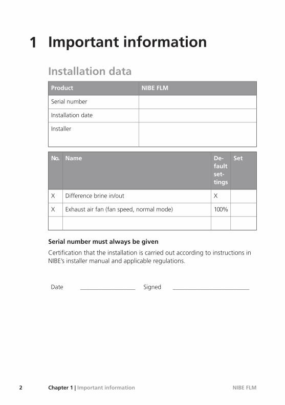
1 Important information
Installation dataNIBE FLMProduct
Serial number
Installation date
Installer
SetDe-faultset-tings
NameNo.
XDifference brine in/outX
100%Exhaust air fan (fan speed, normal mode)X
Serial number must always be given
Certification that the installation is carried out according to instructions inNIBE’s installer manual and applicable regulations.
_________________________Signed__________________Date
NIBE FLMChapter 1 | Important information2

Safety informationThis appliance is not intended for use by persons (including children) withreduced physical, sensory or mental capabilities, or lack of experience andknowledge, unless they have been given supervision or instruction concerninguse of the appliance by a person responsible for their safety.Children should be supervised to ensure that they do not play with the appli-ance.Rights to make any design or technical modifications are reserved.©NIBE 2008.
Symbols
NOTE
This symbol indicates danger to machine or person.
Caution
This symbol indicates important information about what you should observewhen maintaining your installation.
TIP
This symbol indicates tips on how to facilitate using the product.
Marking
This exhaust air module is CE marked and fulfils IP21.
The CE marking means that NIBE ensures that the product meets all regula-tions that are placed on it based on relevant EU directives. The CE mark isobligatory for most products sold in the EU, regardless where they are made.
IP21 means that the product can be touched by hand, that objects with adiameter larger than or equivalent to 12.5 mm cannot penetrate and causedamage and that the product is protected against vertically falling drops.
3NIBE FLMChapter 1 | Important information

Serial numberThe serial number can be found at the bottom left of the front cover.
LEK
Serial number
Caution
Always give the product's serial number when reporting a fault.
NIBE FLMChapter 1 | Important information4

Contact informationKNV Energietechnik GmbH, Gahberggasse 11, 4861 SchörflingAT
Tel: +43 (0)7662 8963-0 Fax: +43 (0)7662 8963-44 E-mail: [email protected] Wärmetechnik AG, Winterthurerstrasse 710, CH-8247 FlurlingenCH
Tel: (52) 647 00 30 Fax: (52) 647 00 31 E-mail: [email protected] www.nibe.chDruzstevni zavody Drazice s.r.o, Drazice 69, CZ - 294 71 Benatky nadJizerou
CZ
Tel: +420 326 373 801 Fax: +420 326 373 803 E-mail: [email protected] Systemtechnik GmbH, Am Reiherpfahl 3, 29223 CelleDE
Tel: 05141/7546-0 Fax: 05141/7546-99 E-mail: [email protected] www.nibe.deVølund Varmeteknik, Filial af NIBE AB, Brogårdsvej 7, 6920 VidebækDK
Tel: 97 17 20 33 Fax: 97 17 29 33 E-mail: [email protected] www.volund-vt.dkNIBE – Haato OY, Valimotie 27, 01510 VantaaFI
Puh: 09-274 697 0 Fax: 09-274 697 40 E-mail: [email protected] Energy Systems Ltd, 3C Broom Business Park, Bridge Way,Chesterfield S41 9QG
GB
Tel: 0845 095 1200 Fax: 0845 095 1201 E-mail: [email protected] Energietechniek B.V., Postbus 2, NL-4797 ZG WILLEMSTAD (NB)NL
Tel: 0168 477722 Fax: 0168 476998 E-mail: [email protected] www.nibenl.nlNIBE AB, Fekjan 15F, 1394 NesbruNO
Tel: 22 90 66 00 Fax: 22 90 66 09 E-mail: [email protected] www.nibevillav-arme.noNIBE-BIAWAR Sp. z o. o. Aleja Jana Pawła II 57, 15-703 BIAŁYSTOKPL
Tel: 085 662 84 90 Fax: 085 662 84 14 E-mail: [email protected] AB Sweden, Box 14, Järnvägsgatan 40, SE-285 21 MarkarydSE
Tel: +46-(0)433-73 000 Fax: +46-(0)433-73 190 E-mail: [email protected]
5NIBE FLMChapter 1 | Important information

NIBE FLM – An excellent choiceNIBE FLM is part of a new generation of heating products that have beendeveloped to supply your house with cheap and environmentally friendlyheating and/or cooling in the most efficient way. NIBE FLM combines recyclingof mechanical exhaust air with a ground-source heat pump and can be con-nected to any NIBE F1145/F1245. NIBE FLM gives a better indoor climate, in-creases the output of the heat pump and means that in certain cases thelength of the collector coil can be reduced. The energy that is in the accom-modation's indoor air can be used to recharge the borehole/collection coil.
Excellent properties for NIBE FLM:DC fan
An energy efficient DC fan (Class A) is integrated in the exhaust air mod-ule.
Low noise level
The exhaust air module has a very low noise level.
Easy to install
The exhaust air module is easy to install together with Nibe F1145/F1245or other heat pump. When installing together with F1145/F1245, the ex-haust air module is connected to the heat pump, which enables you toread off the exhaust air module's values from the heat pump's display.
NIBE FLMChapter 1 | Important information6

2 The heating installation – theheart of the house
Värmebärare
Köldmedium
Köldbärare
Förångare
Kondensor 100 °C
-2 °C
Expansionsventil Kompressor
50 °C40 °C
22 °C 0 °C
Värmekälla
Rumsluft
-3 °C 0 °C
22 °C0 °C
DF
C
E
G
A
B
J
K
Brine
Heat source
Room air
Refrigerant
Heatingmedium
Evaporator
Condenser
Expansion valve Compressor
The temperatures are only examples and may vary between different installations and timeof year.
7NIBE FLMChapter 2 | The heating installation – the heart of the house

The function of the exhaust air moduleAn exhaust air module uses the heat that is in the building's ventilation airto heat up the brine.
Brine circuit and ventilation airIn a hose, collector, an anti-freeze liquid, brine, circulates from the heat pumpout to the heat source (rock/ground/lake). The energy from the heat source isstored by it heating the brine a few degrees, from about –3°C to about 0 °C.
A
The collector then routes the brine to the heat pump’s evaporator. Here, thebrine releases heat energy and the temperature drops a few degrees. The liquidthen returns to the heat source to retrieve energy again.
B
The hot air is transferred from the rooms to the heat pump via the exhaust airmodule.
J
The fan then routes the air to the exhaust air module heat exchanger. Here, theair releases the heating energy to the brine and the air's temperature drops signi-ficantly. The cold air is then blown out of the house.
K
Refrigerant circuitAnother liquid circulates in a closed system in the heat pump, a refrigerant, whichalso passes the evaporator. The refrigerant has a very low boiling point. In theevaporator the refrigerant receives the heat energy from the brine and starts toboil.
C
The gas that is produced during boiling is routed into an electrically poweredcompressor. When the gas is compressed, the pressure increases and the gas'stemperature increases considerably, from 5 °C to approx. 100°C.
D
From the compressor, gas is forced into a heat exchanger, condenser, where itreleases heat energy to the heating system in the house, whereupon the gas iscooled and condenses to a liquid form again.
E
As the pressure is still high, the refrigerant can pass an expansion valve, wherethe pressure drops so that the refrigerant returns to its original temperature. Therefrigerant has now completed a full cycle. It is routed to the evaporator againand the process is repeated.
F
The temperatures are only examples and may vary between different installations and timeof year.
NIBE FLMChapter 2 | The heating installation – the heart of the house8

Maintenance of NIBE FLMRegular checks
Your exhaust air module requires minimal maintenance after commissioning.On the other hand, it is recommended that you check your installation regu-larly.
If NIBE FLM is installed together with Nibe F1145/F1245 and something un-toward occurs, a message appears regarding the operating disturbance inthe form of different alarm texts in the display for F1145/F1245.
Cleaning the ventilation devices
The building’s ventilation devices should becleaned regularly with, for example, a small brushto maintain the correct ventilation.
The device settings must not be changed.
NOTE
If you take down more than one ventilationdevice for cleaning, do not mix them up.
9NIBE FLMChapter 2 | The heating installation – the heart of the house

Cleaning the air filter
Clean NIBE FLM's air filter regularly, how often depends on the amount ofdust in the ventilation air (every three months is recommended).
If NIBE FLM is connected to F1145/F1245, an alarm indication occurs in thedisplay when it is time to clean the filter. The default setting for alarm indic-ation is every three months.
1. Set the switch to "O".
2. Switch off the heat pump.
3. Remove the upper front cover by pulling straight out.
4. Pull out the filter cassette.
5. Remove the filter and shake/vacuum it clean. Check that the filter is notdamaged.
6. Carry out assembly in reverse order.
Even if the filter appears clean, dirt collects in it and this affects the efficiencyof the filter. Therefore, replace it after 2 years. New filters can be ordered viathe installer.
Switch
LEKLEK
NIBE FLMChapter 2 | The heating installation – the heart of the house10

Checking the condensation water seal
LEK
Check that there is water in the water seal. If the water seal is empty or hasa very low water level so that it "gurgles" water can be topped up.
After a period of operation dust and other particles can clog the water seal,consequently, you should check this regularly and clean when necessary.
11NIBE FLMChapter 2 | The heating installation – the heart of the house

3 Disturbances in comfort
If NIBE FLM is not installed together with F1145/F1245, go directly to sectionTroubleshooting on page 14.
In most cases, the heat pump (F1145/F1245) notes operational interference(operational interference can lead to disturbance in comfort) and indicatesthis with alarms and shows action instructions in the display.
Info-menu (F1145/F1245)All the heat pump measurement values are gathered under menu 3.1 in theheat pump menu system. Looking through the values in this menu can oftensimplify finding the fault source.
Manage alarm (F1145/F1245)
info / action
reset alarm
aid mode
Level sensor Brine
alarm
In the event of an alarm, some kind of malfunction has occurred, which isindicated by the status lamp changing from green continuously to red con-tinuously. In addition, an alarm bell appears in the information window.
Alarm
In the event of an alarm with a red status lamp a malfunction has occurredthat the heat pump cannot remedy itself. In the display, by turning the controlknob and pressing the OK button, you can see the type of alarm it is and resetit. You can also choose to set the heat pump to aid mode.
info / action Here you can read what the alarm means and receive tips onwhat you can do to correct the problem that caused the alarm.
NIBE FLMChapter 3 | Disturbances in comfort12

reset alarm In most cases it is enough to select "reset alarm" to correct theproblem that caused the alarm. If a green light illuminates after selecting"reset alarm" the alarm has been remedied. If a red light is still visible and amenu called ”alarm” is visible in the display, the problem that caused thealarm remains. If the alarm disappears and then returns, contact your installer.
aid mode ”aid mode” is a type of emergency mode. This means that theheat pump produces heat and/or hot water despite there being some kindof problem with the heat pump. This can mean that the heat pump's com-pressor is not running. In this case the immersion heater produces heat and/orhot water.
Problems withNIBE FLM do not affect heat pump operation. You do not needto select "aid mode" in event of problems with NIBE FLM.
Selecting ”aid mode” is not the same as correcting the problem that causedthe alarm. The status lamp will therefore continue to be red.
If the alarm does not reset, contact your installer for suitable remedial action.
NOTE
Always gives the heat pump and exhaust air module serial number whencontacting your installer.
13NIBE FLMChapter 3 | Disturbances in comfort

TroubleshootingIf the malfunction does not appear in the display or NIBE FLM is not connectedto F1145/F1245, the following tips can be used:
Basic actions
Start by checking the following possible fault sources:
That the heat pump is running or that the supply cable to NIBE FLM isconnected.
Group and main fuses of the accommodation.
The property's earth circuit breaker.
Low or a lack of ventilationFilter blocked.
Clean or replace filter (see page 10).
Exhaust air device blocked or throttled down too much.
Check and clean the exhaust air devices (see page 9).
Fan speed in reduced mode.
If NIBE FLM is connected to F1145/F1245: Enter menu 1.2 and select“normal".
If NIBE FLM is connected to another heat pump: Contact your installer!
External switch for changing the fan speed activated.
Check any external switches.
High or distracting ventilationThe ventilation is not adjusted.
Order ventilation adjustment.
Fan speed in forced mode.
If NIBE FLM is connected to F1145/F1245: Enter menu 1.2 and select“normal".
If NIBE FLM is connected to another heat pump: Contact your installer!
External switch for changing the fan speed activated.
Check any external switches.
Filter blocked.
Clean or replace the filter.
NIBE FLMChapter 3 | Disturbances in comfort14

Gurgling soundNot enough water in the water seal.
Fill the water seal with water (see page 11).
Choked water seal.
Check and adjust the condensation water hose (see page 11).
15NIBE FLMChapter 3 | Disturbances in comfort

4 Technical data
Detailed technical specifications for this product can be found in the installa-tion manual (www.nibe.eu).
NIBE FLMChapter 4 | Technical data16

5 Glossary
Brine
Anti-freeze liquid, e.g. ethanol or glycol mixed with water, which transportsheat energy from the heat source (rock/ground/lake) to the heat pump.
Brine side
Brine hoses, any bore holes and the evaporator make up the brine side.
Circulation pump
Pump that circulates liquid in a pipe system.
Climate system
The climate system can also be called the heating and/or cooling system. Thebuilding is cooled or heated using radiators, under floor coils or convectorfans.
Disturbances in comfort
Disturbances in comfort are undesirable changes to the hot water/indoorcomfort, for example if the temperature of the hot water is too low or if theindoor temperature is not at the desired level.
A malfunction in the heat pump can sometimes be noticed in the form of adisturbance in comfort.
In most cases, the heat pump notes operational interference and indicatesthis with alarms and shows instructions in the display.
Efficiency
A measurement of how effective the heat pump is. The higher the value isthe better it is.
Exhaust air
The air that comes from the exhaust air device in the various rooms of theaccommodation, to NIBE FLM.
Exhaust air devices
Valves, usually in the ceiling, in the kitchen/bathroom/clothes closet wherethe exhaust air is drawn in to be forwarded to NIBE FLM.
17NIBE FLMChapter 5 | Glossary

Expansion vessel
Vessel with brine or heating medium fluid with the task of equalising thepressure in the brine or heating medium system.
Extract air
The air that the exhaust air module has retrieved heat from and which hastherefore been cooled. This air is blown out of the building.
Heat exchanger
Device that transfers heat energy from one medium to another without mixingmediums.
NIBE FLMChapter 5 | Glossary18

Item register
CContact information, 5
DDisturbances in comfort, 12
Manage alarm, 12Troubleshooting, 14
GGlossary, 17
IImportant information, 2
Contact information, 5Installation data, 2NIBE FLM – An excellent choice, 6Serial number, 4
Installation data, 2
MMaintenance of NIBE FLM, 9
Regular checks, 9Manage alarm, 12
NNIBE FLM – An excellent choice, 6
RRegular checks, 9
SSerial number, 4
TTechnical data, 16The function of the exhaust air module, 8The heating installation – the heart of thehouse, 7Troubleshooting, 14
19NIBE FLMChapter 6 | Item register
6

NIBE FLMChapter 6 |20


NIBE AB Sweden Järnvägsgatan 40Box 14 SE-285 21 [email protected]