ni pxie-5668r getting started guide - national …getting started guide ni pxie-5668r 26.5 ghz or 14...
TRANSCRIPT

GETTING STARTED GUIDE
NI PXIe-5668R26.5 GHz or 14 GHz Vector Signal Analyzer
Note Before you begin, install and configure your chassis and controller.
This document explains how to install, configure, and test the NI 5668R. The NI 5668R is a26.5 GHz or 14 GHz modular vector signal analyzer (VSA). The NI 5668R ships with theNI-RFSA instrument driver, which you use to program the device. You can also use NI-RFmx,available at ni.com/downloads, to program the device.
The NI 5668R comprises the following devices:• NI PXIe-5606 (NI 5606) RF downconverter• NI PXIe-5624R (NI 5624R) intermediate frequency (IF) digitizer• NI PXIe-5653 (NI 5653) synthesizer/local oscillator (LO) source module
In this document, "NI 5668R" refers to both the NI 5668R 26.5 GHz VSA and the NI 5668R14 GHz VSA unless otherwise specified.
Caution The protection provided by this product may be impaired if it is used in amanner not described in this document.
Hot Surface If the NI 5668R has been in use, it may exceed safe handlingtemperatures and cause burns. Allow the NI 5668R to cool before removing it fromthe chassis.
ContentsElectromagnetic Compatibility Guidelines...............................................................................2Verifying the System Requirements......................................................................................... 2Unpacking the Kit.....................................................................................................................2
Verifying the Kit Contents................................................................................................ 4Preparing the Environment....................................................................................................... 5Choosing and Installing the Software.......................................................................................5
Software Options.............................................................................................................. 5Installing the Software...................................................................................................... 6
Installing the NI 5668R.............................................................................................................7Interconnecting the NI 5668R Modules............................................................................8
Configuring the NI 5668R in MAX........................................................................................20Self-Calibration.......................................................................................................................21
Performing a Device Self-Calibration Using the NI-RFSA SFP....................................22

Locating the Software and Examples..................................................................................... 22Software Locations......................................................................................................... 22Programming Examples Locations.................................................................................25
Troubleshooting...................................................................................................................... 26Installation...................................................................................................................... 26Configuration.................................................................................................................. 27Measurements................................................................................................................. 28
Where to Go Next................................................................................................................... 29Worldwide Support and Services............................................................................................30
Electromagnetic Compatibility GuidelinesThis product was tested and complies with the regulatory requirements and limits forelectromagnetic compatibility (EMC) stated in the product specifications. These requirementsand limits provide reasonable protection against harmful interference when the product isoperated in the intended operational electromagnetic environment.
This product is intended for use in industrial locations. However, harmful interference mayoccur in some installations, when the product is connected to a peripheral device or test object,or if the product is used in residential or commercial areas. To minimize interference withradio and television reception and prevent unacceptable performance degradation, install anduse this product in strict accordance with the instructions in the product documentation.
Furthermore, any changes or modifications to the product not expressly approved by NationalInstruments could void your authority to operate it under your local regulatory rules.
Caution To ensure the specified EMC performance, operate this product only withshielded cables and accessories.
Caution To ensure the specified EMC performance, operate this product only withcables less than 3 meters in length.
Verifying the System RequirementsTo use the NI 5668R, your system must meet certain requirements. For more informationabout minimum system requirements, recommended system, and supported applicationdevelopment environments (ADEs), refer to the readme, which is available on the softwaremedia or online at ni.com/updates.
Unpacking the KitCaution To prevent electrostatic discharge (ESD) from damaging the device,ground yourself using a grounding strap or by holding a grounded object, such asyour computer chassis.
1. Touch the antistatic package to a metal part of the computer chassis.
2 | ni.com | NI PXIe-5668R Getting Started Guide
2. Remove the device from the package and inspect the device for loose components or anyother sign of damage.
Caution Never touch the exposed pins of connectors.
Note Do not install a device if it appears damaged in any way.
3. Unpack any other items and documentation from the kit.
Store the device in the antistatic package when the device is not in use.
NI PXIe-5668R Getting Started Guide | © National Instruments | 3
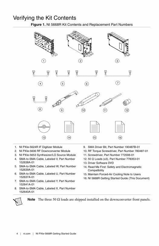
Verifying the Kit ContentsFigure 1. NI 5668R Kit Contents and Replacement Part Numbers
31 2
13 14 15 16
4 6 75
8 10 11 129
1. NI PXIe-5624R IF Digitizer Module2. NI PXIe-5606 RF Downconverter Module3. NI PXIe-5653 Synthesizer/LO Source Module4. SMA-to-SMA Cable, Labeled V, Part Number
152638A-015. SMA-to-SMA Cable, Labeled W, Part Number
152639A-016. SMA-to-SMA Cable, Labeled U, Part Number
152637A-017. SMA-to-SMA Cable, Labeled Y, Part Number
152641A-018. SMA-to-SMA Cable, Labeled X, Part Number
152640A-01
9. SMA Driver Bit, Part Number 190487B-0110. RF Torque Screwdriver, Part Number 780487-0111. Screwdriver, Part Number 772006-0112. 50 Ω Loads (x3), Part Number 778353-0113. Driver Software DVD14. Read Me First: Safety and Electromagnetic
Compatibility15. Maintain Forced-Air Cooling Note to Users16. NI 5668R Getting Started Guide (This Document)
Note The three 50 Ω loads are shipped installed on the downconverter front panels.
4 | ni.com | NI PXIe-5668R Getting Started Guide
Other EquipmentThere are several required items not included in your device kit that you need to operate theNI 5668R. Your application may require additional items not included in your kit to install oroperate your device.• A PXI Express chassis and chassis documentation. The NI PXIe-1085 chassis is one
available option for your device. For more information about compatible chassis options,refer to ni.com.
• An embedded controller or MXI controller system that meets the system requirementsspecified in this guide and chassis documentation.
Preparing the EnvironmentEnsure that the environment you are using the NI 5668R in meets the following specifications.
Operating ambient temperature(IEC 60068-2-1, IEC 60068-2-2)
0 °C to 55 °C
Operating relative humidity(IEC 60068-2-56)
10% to 90%, noncondensing
Maximum altitude 2,000 m (800 mbar) (at 25 °C ambienttemperature)
Pollution Degree 2
Indoor use only.
Caution Clean the hardware with a soft, nonmetallic brush or lint free cloth. Makesure that the hardware is completely dry and free from contaminants beforereturning it to service.
Note Refer to the NI PXIe-5668R Specifications at ni.com/manuals for completespecifications.
Choosing and Installing the Software
Software OptionsNI provides several software options for the NI 5668R—NI-RFmx, the NI-RFSA instrumentdriver software, and the NI-RFSA Soft Front Panel (SFP).
NI PXIe-5668R Getting Started Guide | © National Instruments | 5

Table 1. NI 5668R Software Options
SoftwareOption
Description Use Case
NI-RFmx Provides a single-handleinstrument driver with built-inmeasurements.
Use NI-RFmx SpecAn to performspectral measurements.
Use NI-RFmx Demod to performmodulation quality measurements,such as EVM.
Use NI-RFmx cellular personalities toperform physical layer measurementanalysis on supported cellular signals.
NI-RFSAinstrumentdriver
The NI-RFSA APIs each provide afixed API for interacting with yourNI 5668R device.
NI-RFSA provides standard IVI-based functionality needed formost vector signal analyzerapplications.
Use NI-RFSA to create custommeasurements or applications thatrequire I/Q data.
Use NI-RFSA along with theNI Modulation Toolkit to analyzemodulated signals to test receivers.
NI-RFSA SFP Controls, analyzes, and presentsdata similar to stand-alone RFvector signal analyzers. The NI-RFSA SFP operates on the PC, soit provides processing, storage, anddisplay capabilities.
Use the NI-RFSA SFP to interactivelyacquire data.
Installing the SoftwareYou must be an Administrator to install NI software on your computer.1. Install an ADE, such as LabVIEW or LabWindows™/CVI™.2. Insert the driver software media into your computer. The installer should open
automatically.
If the installation window does not appear, navigate to the drive, double-click it, anddouble-click autorun.exe.
3. Follow the instructions in the installation prompts.
Note Windows users may see access and security messages duringinstallation. Accept the prompts to complete the installation.
4. When the installer completes, select Restart in the dialog box that prompts you to restart,shut down, or restart later.
6 | ni.com | NI PXIe-5668R Getting Started Guide
Installing the NI 5668RCaution To prevent damage to the NI 5668R caused by ESD or contamination,handle the module using the edges or the metal bracket.
You must install NI-RFSA before installing the hardware.
Before you install the hardware, refer to the guidelines in the Maintain Forced-Air CoolingNote to Users included with the module to ensure that the device can cool itself effectively.
To use the included cables, you must install the NI 5624R IF digitizer immediately to the leftof the NI 5606 RF downconverter module, and you must install the NI 5653 LO sourcemodule immediately to the right of the NI 5606 RF downconverter module.1. Ensure the AC power source is connected to the chassis before installing the module.
The AC power cord grounds the chassis and protects it from electrical damage while youinstall the module.
2. Power off the chassis.3. Inspect the slot pins on the chassis backplane for any bends or damage prior to
installation. Do not install a module if the backplane is damaged.4. Remove the black plastic covers from all the captive screws on the module front panel.5. Identify a supported slot in the chassis. The following figure shows the symbols that
indicate the slot types.
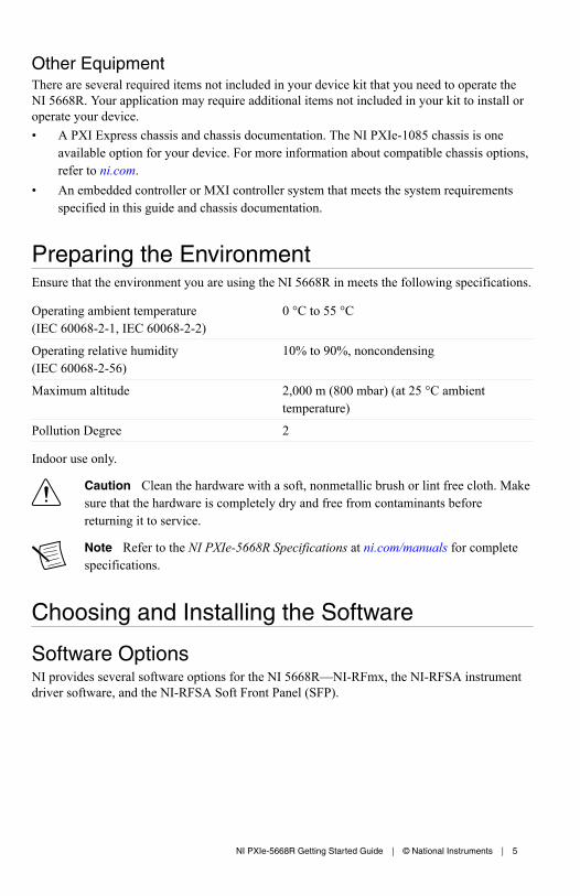
Figure 2. Chassis Compatibility Symbols
NI PXIe-1062Q
1 2 3 4 5
1. PXI Express System Controller Slot2. PXI Peripheral Slot3. PXI Express Hybrid Peripheral Slot
4. PXI Express System Timing Slot5. PXI Express Peripheral Slot
NI 5668R modules can be placed in PXI Express peripheral slots, PXI Express hybridperipheral slots, or PXI Express system timing slots.
6. Touch any metal part of the chassis to discharge static electricity.7. Ensure that the ejector handle is in the downward (unlatched) position.8. Place the module edges into the module guides at the top and bottom of the chassis. Slide
the module into the slot until it is fully inserted.
NI PXIe-5668R Getting Started Guide | © National Instruments | 7

Figure 3. Module Installation
2
3
NI PXIe-1075
1
1. Chassis2. Hardware Module3. Ejector Handle in Downward (Unlatched) Position
9. Latch the module in place by pulling up on the ejector handle.10. Secure the module front panel to the chassis using the front-panel mounting screws.
Note Tightening the top and bottom mounting screws increases mechanicalstability and also electrically connects the front panel to the chassis, which canimprove the signal quality and electromagnetic performance.
11. Cover all empty slots using filler panels or fill using slot blockers to maximize cooling airflow.
12. Power on the chassis.
Related InformationInstalling the Software on page 6
Interconnecting the NI 5668R ModulesComplete the following steps to interconnect the NI 5668R front panel connectors, as shownin the following figure.
Caution The signal pins of this product's input/output ports can be damaged ifsubjected to ESD. To prevent damage, remove power from the product before
8 | ni.com | NI PXIe-5668R Getting Started Guide
connecting cables and employ industry-standard ESD prevention measures duringinstallation, maintenance, and operation.
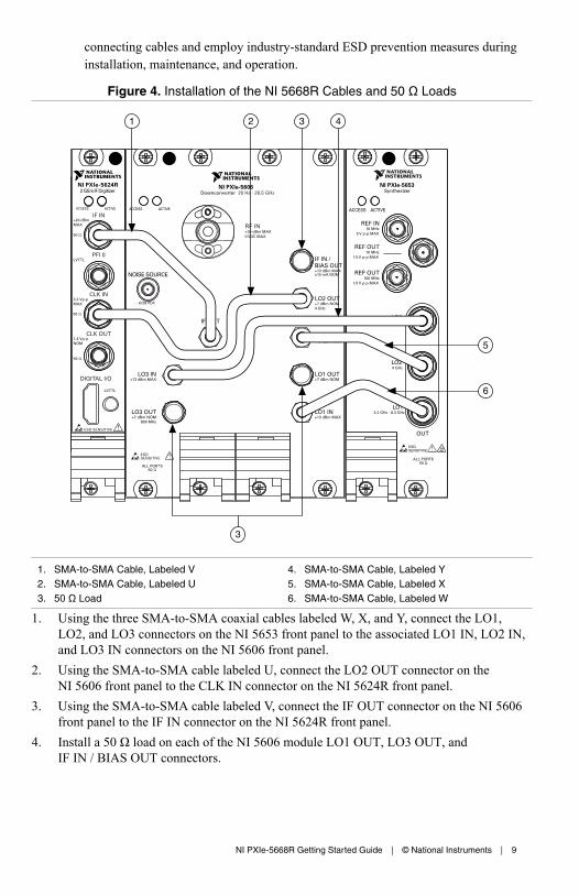
Figure 4. Installation of the NI 5668R Cables and 50 Ω Loads
ACCESS ACTIVE
431
5
6
2
3
1. SMA-to-SMA Cable, Labeled V2. SMA-to-SMA Cable, Labeled U3. 50 Ω Load
4. SMA-to-SMA Cable, Labeled Y5. SMA-to-SMA Cable, Labeled X6. SMA-to-SMA Cable, Labeled W
1. Using the three SMA-to-SMA coaxial cables labeled W, X, and Y, connect the LO1,LO2, and LO3 connectors on the NI 5653 front panel to the associated LO1 IN, LO2 IN,and LO3 IN connectors on the NI 5606 front panel.
2. Using the SMA-to-SMA cable labeled U, connect the LO2 OUT connector on theNI 5606 front panel to the CLK IN connector on the NI 5624R front panel.
3. Using the SMA-to-SMA cable labeled V, connect the IF OUT connector on the NI 5606front panel to the IF IN connector on the NI 5624R front panel.
4. Install a 50 Ω load on each of the NI 5606 module LO1 OUT, LO3 OUT, andIF IN / BIAS OUT connectors.
NI PXIe-5668R Getting Started Guide | © National Instruments | 9
5. Hand-tighten all SMA cable ends on the SMA connectors after the cable center pins arecorrectly aligned and connected. The cable connectors should tighten without muchtorque or effort.
Note If the SMA cable does not exactly align with the SMA connector, bendthe cable slightly by hand to align the cable and the connector. The amount ofbending should be minimal. The cables can be damaged by excessive bending.
6. Carefully complete tightening all SMA connectors to 1 N · m using an appropriate torquewrench (not included) or torque screwdriver and SMA driver bit. Tighten only until thewrench clicks.
Caution Incorrect torque at SMA connections can damage device connectors,degrade signal fidelity and phase locked loop performance, or cause insertionloss. Use an appropriate torque wrench or torque screwdriver and SMA driverbit to ensure all SMA connections are properly torqued. SMA connectors forconnections to external equipment may require torque different from 1 N · m,depending on the connector type, material, and manufacturer.
7. Power on your PXI Express chassis and controller system. If you are using a MXI deviceand a remote controller, ensure that the chassis is powered on prior to triggering theremote controller. Using the controller system before the chassis is powered on maycause installed devices to not appear in MAX.
8. Verify that the ACCESS LED is on for all three modules.
Related InformationTroubleshooting on page 26
If an issue persists after you complete a troubleshooting procedure, contact NI technicalsupport or visit ni.com/support.
Refer to the NI RF Vector Signal Analyzers Help for information about how to makeconnections using an external clock, or how to connect multiple NI 5668R modules.
Direct Connections to the NI 5606The NI 5606 is a precision RF instrument that is sensitive to ESD and transients. Ensure youare making proper direct connections to the NI 5606 to avoid damaging the device.
Caution Apply external signals only while the NI 5606 is powered on. Applyingexternal signals while the device is powered off may cause damage.
• Ensure you are properly grounded when manipulating cables or antennas connected to theNI 5606 RF IN connector.
• If you are using noninsulated devices, such as an RF antenna, ensure the devices aremaintained in a static-free environment.
• If you are using an active device, such as a preamplifier or switch routed to the NI 5606RF IN connector, ensure that the device cannot generate signal transients greater than theRF and DC specifications of the NI 5606 RF IN connector.
10 | ni.com | NI PXIe-5668R Getting Started Guide
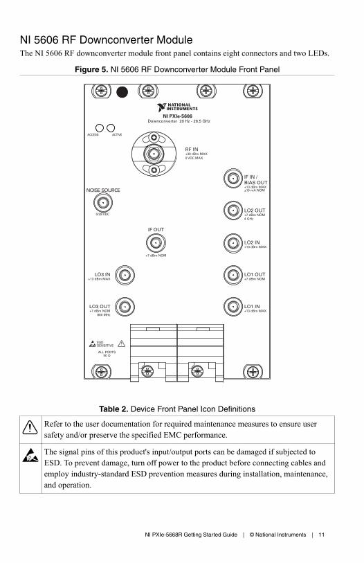
NI 5606 RF Downconverter ModuleThe NI 5606 RF downconverter module front panel contains eight connectors and two LEDs.
Figure 5. NI 5606 RF Downconverter Module Front Panel
Table 2. Device Front Panel Icon Definitions
Refer to the user documentation for required maintenance measures to ensure usersafety and/or preserve the specified EMC performance.
The signal pins of this product's input/output ports can be damaged if subjected toESD. To prevent damage, turn off power to the product before connecting cables andemploy industry-standard ESD prevention measures during installation, maintenance,and operation.
NI PXIe-5668R Getting Started Guide | © National Instruments | 11

Table 3. NI 5606 RF Downconverter Front Panel Connectors
Connector Use
RF IN Connects to the analog RF input signal to be measured by the vector signalanalyzer. The maximum RF input is +30 dBm.
Note The NI 5606 downconverter module has no internal DCblock. High-frequency components in the NI 5606 can bedamaged when DC signals are applied directly to the RF INconnector. The NI 5606 ships with a 2.92 mm DC blockattached to the RF IN connector to prevent damage to the devicewhen a DC input signal is present. The DC block must beremoved to make measurements below 16 kHz. NI recommendsthat you keep the DC block attached to the RF IN connector forall measurements at frequencies greater than or equal to 16 kHzto maximize the accuracy of the device. To prevent damage tothe downconverter, ensure that the DC voltage at the RF INconnector is between -2 VDC and +2 VDC. With the DC blockremoved, the maximum allowed voltage is 0 VDC.
Caution To reinstall the DC block on the NI 5606 RF INconnector, use a torque wrench set to a maximum torque of1.65 N · m (15 lb · in.). Using more than the recommendedamount of torque may damage the RF IN connector.
IF OUT Connects to the IF IN connector on the NI 5624R module front panel.
This connector is the output terminal for the frequency-translated IF signal.
LO1 IN Connects to the LO1 OUT connector on the NI 5653 module front panel.
This connector is the input terminal for the LO1 (3.2 GHz to 8.3 GHz)source. LO1 IN is an SMA connector with an impedance of 50 Ω(nominal).
LO2 IN Connects to the LO2 OUT connector on the NI 5653 module front panel.
This connector is the input terminal for the LO2 (4 GHz) source. LO2 IN isan SMA connector with an impedance of 50 Ω (nominal).
LO3 IN Connects to the LO3 OUT connector on the NI 5653 module front panel.
This connector is the input terminal for the LO3 (800 MHz) source. LO3IN is an SMA connector with an impedance of 50 Ω (nominal).
12 | ni.com | NI PXIe-5668R Getting Started Guide
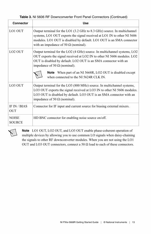
Table 3. NI 5606 RF Downconverter Front Panel Connectors (Continued)
Connector Use
LO1 OUT Output terminal for the LO1 (3.2 GHz to 8.3 GHz) source. In multichannelsystems, LO1 OUT exports the signal received at LO1 IN to other NI 5606modules. LO1 OUT is disabled by default. LO1 OUT is an SMA connectorwith an impedance of 50 Ω (nominal).
LO2 OUT Output terminal for the LO2 (4 GHz) source. In multichannel systems, LO2OUT exports the signal received at LO2 IN to other NI 5606 modules. LO2OUT is disabled by default. LO2 OUT is an SMA connector with animpedance of 50 Ω (nominal).
Note When part of an NI 5668R, LO2 OUT is disabled exceptwhen connected to the NI 5624R CLK IN.
LO3 OUT Output terminal for the LO3 (800 MHz) source. In multichannel systems,LO3 OUT exports the signal received at LO3 IN to other NI 5606 modules.LO3 OUT is disabled by default. LO3 OUT is an SMA connector with animpedance of 50 Ω (nominal).
IF IN / BIASOUT
Connector for IF input and current source for biasing external mixers.
NOISESOURCE
HD BNC connector for enabling noise source on/off.
Note LO1 OUT, LO2 OUT, and LO3 OUT enable phase-coherent operation ofmultiple devices by allowing you to use common LO signals when daisy-chainingthe signals to other RF downconverter modules. When you are not using the LO1OUT and LO3 OUT connectors, connect a 50 Ω load to each of these connectors.
NI PXIe-5668R Getting Started Guide | © National Instruments | 13
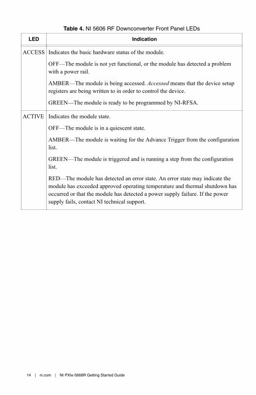
Table 4. NI 5606 RF Downconverter Front Panel LEDs
LED Indication
ACCESS Indicates the basic hardware status of the module.
OFF—The module is not yet functional, or the module has detected a problemwith a power rail.
AMBER—The module is being accessed. Accessed means that the device setupregisters are being written to in order to control the device.
GREEN—The module is ready to be programmed by NI-RFSA.
ACTIVE Indicates the module state.
OFF—The module is in a quiescent state.
AMBER—The module is waiting for the Advance Trigger from the configurationlist.
GREEN—The module is triggered and is running a step from the configurationlist.
RED—The module has detected an error state. An error state may indicate themodule has exceeded approved operating temperature and thermal shutdown hasoccurred or that the module has detected a power supply failure. If the powersupply fails, contact NI technical support.
14 | ni.com | NI PXIe-5668R Getting Started Guide
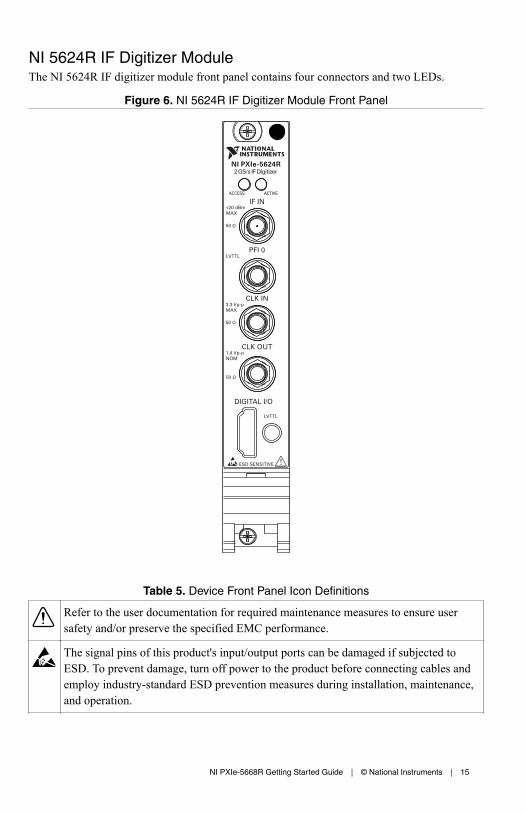
NI 5624R IF Digitizer ModuleThe NI 5624R IF digitizer module front panel contains four connectors and two LEDs.
Figure 6. NI 5624R IF Digitizer Module Front Panel
ACCESS ACTIVE
Table 5. Device Front Panel Icon Definitions
Refer to the user documentation for required maintenance measures to ensure usersafety and/or preserve the specified EMC performance.
The signal pins of this product's input/output ports can be damaged if subjected toESD. To prevent damage, turn off power to the product before connecting cables andemploy industry-standard ESD prevention measures during installation, maintenance,and operation.
NI PXIe-5668R Getting Started Guide | © National Instruments | 15

Table 6. NI 5624R IF Digitizer Front Panel Connectors
Connector Use
IF IN Connects to the IF OUT connector on the NI 5606 front panel. Thisconnector is the input terminal for a frequency-translated IF waveform fromthe RF downconverter, filtered by the NI 5606, for digitization andmeasurement. IF IN is an SMA connector with a nominal input impedance of50 Ω. When used in a NI 5668R the IF IN connector has a +6 dBm full-scaleinput level and a -6 dBm nominal input level. The IF IN connector damagelevel is +20 dBm.
CLK IN Connects to the LO2 OUT connector on the NI 5606 module. The CLK INconnector is the input terminal for the Reference or Sample Clock (ADCClock). CLK IN is an SMA connector with a nominal input impedance of50 Ω.
CLK OUT The CLK OUT connector is the output terminal for the NI 5624R PLLReference or Sample Clock (ADC Clock). CLK OUT is an SMA connectorwith a nominal output impedance of 50 Ω. The output power delivered to a50 Ω load is >10 dBm.
PFI 0 Receives a digital trigger from an external source. PFI 0 is an SMA connectorand has LVTTL.
DIGITAL I/O DIO terminal that contains general-purpose DIO signals. DIO lines are notaccessible using NI-RFSA.
Caution The DIGITAL I/O connector accepts a standard, third-party HDMI™
cable, but the DIGITAL I/O port is not an HDMI interface. Do not connect the
16 | ni.com | NI PXIe-5668R Getting Started Guide

DIGITAL I/O port on the NI 5624 to the HDMI port of another device. NI is notliable for any damage resulting from such signal connections.
Table 7. NI 5624R IF Digitizer Front Panel LEDs
LED Indication
ACCESS Indicates the basic hardware status of the NI 5624R module.
OFF—The module is not yet functional, or the module has detected a problemwith a PXI Express power rail.
AMBER—The module is being accessed. Accessed means that the device setupregisters are being written to in order to control the device.
GREEN—The module is ready to be programmed by NI-RFSA.
RED—The module has exceeded the approved operation temperature and thermalshutdown has occurred.
ACTIVE Indicates the NI 5624R module state.
OFF—The module is not armed, triggered, or acquiring a waveform.
AMBER—The module is armed and waiting for a trigger.
GREEN—The module has received a Reference Trigger. A green LED alsoindicates that the module is acquiring a waveform.
RED—The module has detected an error. NI-RFSA must access the module todetermine the cause of the error. The LED remains red until the error condition isremoved.
NI PXIe-5668R Getting Started Guide | © National Instruments | 17
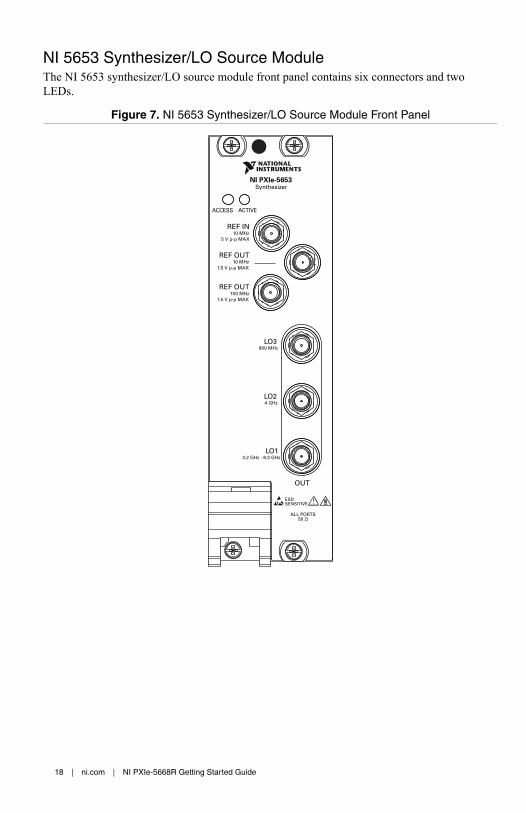
NI 5653 Synthesizer/LO Source ModuleThe NI 5653 synthesizer/LO source module front panel contains six connectors and twoLEDs.
Figure 7. NI 5653 Synthesizer/LO Source Module Front Panel
ESDSENSITIVE
ACCESS ACTIVE
LO3 800 MHz
LO2 4 GHz
LO1 3.2 GHz - 8.3 GHz
OUT
ALL PORTS50 Ω
NI PXIe-5653Synthesizer
REF IN10 MHz
5 V p-p MAX
REF OUT10 MHz
1.5 V p-p MAX
REF OUT 100 MHz
1.5 V p-p MAX
18 | ni.com | NI PXIe-5668R Getting Started Guide

Table 8. Device Front Panel Icon Definitions
Refer to the user documentation for required maintenance measures to ensure usersafety and/or preserve the specified EMC performance.
The signal pins of this product's input/output ports can be damaged if subjected toESD. To prevent damage, turn off power to the product before connecting cables andemploy industry-standard ESD prevention measures during installation, maintenance,and operation.
If this device has been in use, it may exceed safe handling temperatures and causeburns. Allow the device to cool before removing it from the chassis.
Table 9. NI 5653 Synthesizer/LO Source Front Panel Connectors
Connector Use
REF IN Routes a frequency reference signal to the RF synthesizer/LO source.
This connector accepts a 10 MHz frequency signal with a maximumvoltage of 2 Vpk-pk.
REF OUT(10 MHz)
Routes a frequency reference signal from the synthesizer/LO moduleonboard 10 MHz oven-controlled crystal oscillator (OCXO).
REF OUT(100 MHz)
Routes a frequency reference signal from the synthesizer onboard100 MHz OCXO.
LO1 OUT Connects to the LO1 IN connector on the NI 5606 module front panel.
This connector is the output terminal for the LO1 (3.2 GHz to8.3 GHz) source. LO1 OUT is an SMA connector with an impedanceof 50 Ω (nominal).
LO2 OUT Connects to the LO2 IN connector on the NI 5606 module front panel.
This connector is the output terminal for the LO2 (4 GHz) source.LO2 OUT is an SMA connector with an impedance of 50 Ω(nominal).
LO3 OUT Connects to the LO3 IN connector on the NI 5606 module front panel.
This connector is the output terminal for the LO3 (800 MHz) source.LO3 OUT is an SMA connector with an impedance of 50 Ω(nominal).
NI PXIe-5668R Getting Started Guide | © National Instruments | 19
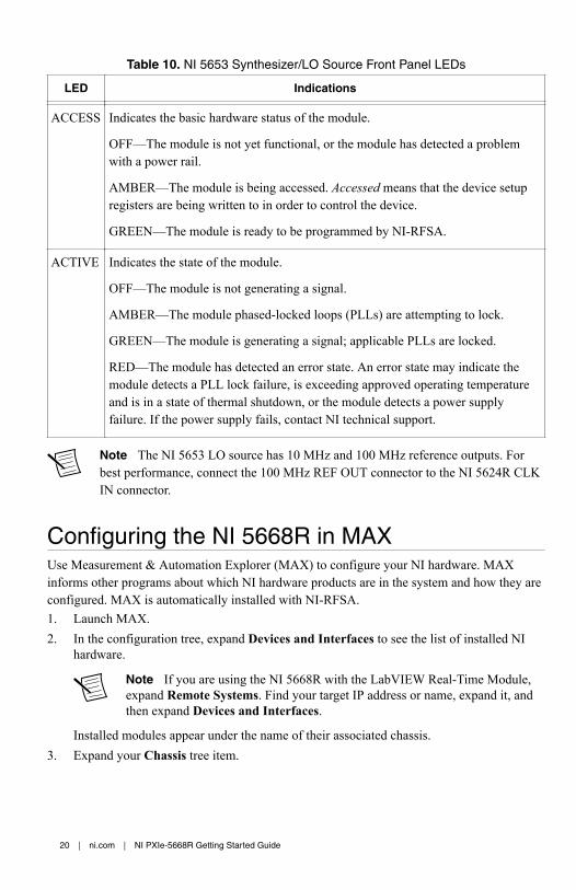
Table 10. NI 5653 Synthesizer/LO Source Front Panel LEDs
LED Indications
ACCESS Indicates the basic hardware status of the module.
OFF—The module is not yet functional, or the module has detected a problemwith a power rail.
AMBER—The module is being accessed. Accessed means that the device setupregisters are being written to in order to control the device.
GREEN—The module is ready to be programmed by NI-RFSA.
ACTIVE Indicates the state of the module.
OFF—The module is not generating a signal.
AMBER—The module phased-locked loops (PLLs) are attempting to lock.
GREEN—The module is generating a signal; applicable PLLs are locked.
RED—The module has detected an error state. An error state may indicate themodule detects a PLL lock failure, is exceeding approved operating temperatureand is in a state of thermal shutdown, or the module detects a power supplyfailure. If the power supply fails, contact NI technical support.
Note The NI 5653 LO source has 10 MHz and 100 MHz reference outputs. Forbest performance, connect the 100 MHz REF OUT connector to the NI 5624R CLKIN connector.
Configuring the NI 5668R in MAXUse Measurement & Automation Explorer (MAX) to configure your NI hardware. MAXinforms other programs about which NI hardware products are in the system and how they areconfigured. MAX is automatically installed with NI-RFSA.1. Launch MAX.2. In the configuration tree, expand Devices and Interfaces to see the list of installed NI
hardware.
Note If you are using the NI 5668R with the LabVIEW Real-Time Module,expand Remote Systems. Find your target IP address or name, expand it, andthen expand Devices and Interfaces.
Installed modules appear under the name of their associated chassis.3. Expand your Chassis tree item.
20 | ni.com | NI PXIe-5668R Getting Started Guide

MAX lists all modules installed in the chassis. Your default names may vary.
Note If you do not see your module listed, press <F5> to refresh the list ofinstalled modules. If the module is still not listed, power off the system, ensurethe module is correctly installed, and restart.
4. Record the identifier MAX assigns to the hardware. Use this identifier whenprogramming the NI 5668R.
5. Associate the hardware modules that comprise your device.a) Select the NI 5606 that is identified as not configured in the configuration tree.b) In the Associated Devices section, select the appropriate module from each system
component drop-down listbox.
For the NI 5668R, you must associate the NI 5624R IF digitizer module and theNI 5653 LO source module with the NI 5606 RF downconverter.
c) Click Save in the MAX toolbar.
Note Module associations may be lost when you move the modules todifferent chassis slots.
6. Self-test the device modules by selecting the modules in the configuration tree, andclicking Self-Test in the MAX toolbar. Repeat this step for all modules in your NI 5668Rsystem.
The MAX self-test performs a basic verification of hardware resources.
Related InformationTroubleshooting on page 26
If an issue persists after you complete a troubleshooting procedure, contact NI technicalsupport or visit ni.com/support.
Interconnecting the NI 5668R Modules on page 8Refer to the NI RF Vector Signal Analyzers Help for more information about renamingdevices.
Self-CalibrationIt is important to perform a self-calibration after first connecting your system because ofcabling and mismatch effects and some degree of residual error, which result from moduleinterconnections. You can determine and reduce these undesired effects through self-calibration, which adjusts the NI 5668R with respect to an onboard high-precision calibrationtone. Additionally, you should periodically run a self-calibration to adjust for performancedrifts that occur with product aging.
The NI 5668R modules are independently calibrated at the factory; however, you shouldperform a self-calibration in any of the following situations:• After first installing and interconnecting your NI 5668R system• When there is a physical change to any of the system components, such as replacement of
modules
NI PXIe-5668R Getting Started Guide | © National Instruments | 21

• When there is a change to the system cabling• When the system is in an environment where external variables, such as temperature, can
affect measurements
You should also perform a self-calibration if your device has exceeded any of the followingtemperature or time limits since the last device self-calibration:• IF flatness: ±5 °C and/or 7 days• Gain reference: ±5 °C and/or 7 days• LO self-calibration: ±10 °C and/or 30 days• Preselector alignment: ±5 °C and/or 7 days
Performing a Device Self-Calibration Using theNI-RFSA SFPNI recommends you run the self-calibration from the NI-RFSA SFP. You can also run a self-calibration programmatically using the NI-RFSA API.1. Launch the NI-RFSA SFP by navigating to Start»All Programs»National
Instruments»NI-RFSA»NI-RFSA Soft Front Panel.2. Click Device/System»Calibration»Self Calibration.3. Select the self-calibration steps you want to perform from the Self-Calibration dialog
box.4. Click Next to run the self-calibration.
Locating the Software and Examples
Software Locations
Table 11. Locations of NI-RFmx Software
ADE Location
LabVIEW Available on the LabVIEW Functions palette at MeasurementI/O»NI-RFmx.
LabWindows/CVI NI-RFmx functions are available from the LabWindows/CVILibrary menu at Library»RFmx SpecAn Library and Library»RFmx Demod Library.
22 | ni.com | NI PXIe-5668R Getting Started Guide

Table 11. Locations of NI-RFmx Software (Continued)
ADE Location
Microsoft Visual C/C++ Use the header files located in the <NIDir>\Shared\ExternalCompilerSupport\C\include directory andimport library files located in one of the following directories:• Windows 10 (32-bit)/8.1 (32-bit)/7 (32-bit)—<NIDir>
\Shared\ExternalCompilerSupport\C\include• Windows 10 (64-bit)/8.1 (64-bit)/7 (64-bit):
– 32-bit installation—<NIDir>\Shared\ExternalCompilerSupport\C\lib32\msvc
– 64-bit installation—<NIDir>\Shared\ExternalCompilerSupport\C\lib64\msvc
where <NIDir> is one of the following locations:• Windows 10 (32-bit)/8.1 (32-bit)/7 (32-bit)—Program
Files\National Instruments• Windows 10 (64-bit)/8.1 (64-bit)/7 (64-bit)—Program
Files (x86)\National Instruments
Microsoft .NET For the location of .NET class libraries, refer to the installedNI-RFmx readme.
NI PXIe-5668R Getting Started Guide | © National Instruments | 23

Table 12. Locations of NI-RFSA and NI-RFSA SFP Software
SoftwareOption
ADE Location
NI-RFSA LabVIEW Available on the LabVIEW Functions palette atMeasurement I/O»NI-RFSA.
LabWindows/CVI Available in the <IVIROOTDIR32>\Drivers\niRFSA directory, where <IVIROOTDIR32>is one of the following locations:• Windows 10 (32-bit)/8.1 (32-bit)/7 (32-bit)
—Program Files\IVI Foundation\IVI
• Windows 10 (64-bit)/8.1 (64-bit)/7 (64-bit)—Program Files (x86)\IVIFoundation\IVI
Microsoft Visual C/C++ Use the header files located in the<IVIROOTDIR32>\Include directory andimport library files located in the<IVIROOTDIR32>\Lib directory, where<IVIROOTDIR32> is one of the followingdirectories:• Windows 10 (32-bit)/8.1 (32-bit)/7 (32-bit)
—Program Files\IVI Foundation\IVI
• Windows 10 (64-bit)/8.1 (64-bit)/7 (64-bit)—Program Files (x86)\IVIFoundation\IVI
Microsoft .NET To use the .NET API, you must install the .NETclass libraries. For download and installed filelocations, visit ni.com/info and enter Info CodeNETAPIdriversupport.
24 | ni.com | NI PXIe-5668R Getting Started Guide

Table 12. Locations of NI-RFSA and NI-RFSA SFP Software (Continued)
SoftwareOption
ADE Location
NI-RFSA SFP LabVIEW Available from the Start Menu at Start»AllPrograms»National Instruments»NI-RFSA»NI-RFSA Soft Front Panel.
Related InformationRefer to the Getting Started with NI-RFSA section of the NI RF Vector Signal Analyzers Helpfor detailed instructions about how to acquire data in a specific ADE.Refer to the Creating an Application with Microsoft Visual C and C++ topic of the NI RFVector Signal Analyzers Help if you prefer to manually add all required include and libraryfiles to the project.
Programming Examples Locations
Using the NI Example FinderIf you're using NI-RFmx or NI-RFSA with LabVIEW or LabWindows/CVI, use theNI Example Finder to locate programming examples.1. Launch LabVIEW or LabWindows/CVI.2. Select Help»Find Examples to open the NI Example Finder.3. Navigate to Hardware Input and Output»Modular Instruments.4. Open the example that best matches your application requirements.
NI PXIe-5668R Getting Started Guide | © National Instruments | 25

Using Microsoft Visual C/C++If you're using NI-RFmx or NI-RFSA with Microsoft Visual C/C++, locate examples in thefollowing directories.
Table 13. Location of Microsoft Visual C/C++ Programming Examples
Software Option Examples Location
NI-RFmx <NIDocDir>\RFmx\Demod\Examples
<NIDocDir>\RFmx\SpecAn\Examples
where <NIDocDir> is the Users\Public\Public Documents\National Instruments directory.
NI-RFSA <NIDocDir>\NI-RFSA\examples
where <NIDocDir> is the Users\Public\Public Documents\National Instruments directory.
Note LabVIEW examples that demonstrate integration of the NI 5668R with NIRF vector signal generators and NI toolkit software, including the NI ModulationToolkit, are also available online at ni.com/examples.
TroubleshootingIf an issue persists after you complete a troubleshooting procedure, contact NI technicalsupport or visit ni.com/support.
Related InformationInterconnecting the NI 5668R Modules on page 8
Installation
Why Is the ACCESS LED Off When the Chassis Is On?The LEDs may not light until the device has been configured in MAX. Before proceeding,verify that the NI 5668R appears in MAX.
If the ACCESS LED fails to light after you power on the chassis, a problem may exist with thechassis power rails, a hardware module, or the LED.
Caution Apply external signals only while the NI 5668R is powered on. Applyingexternal signals while the device is powered off may cause damage.
1. Disconnect any signals from the module front panels.2. Power off the chassis.
26 | ni.com | NI PXIe-5668R Getting Started Guide

3. Remove the module from the chassis and inspect it for damage. Do not reinstall adamaged device.
4. Reinstall the module in a different chassis slot.5. Power on the chassis.6. Verify that the device appears in MAX.7. Reset the device in MAX and perform a self-test.
What Should I Do if the NI 5668R Doesn't Appear in MAX?1. In the MAX configuration tree, expand Devices and Interfaces.2. Expand the Chassis tree to see the list of installed hardware, and press <F5> to refresh
the list.3. If the module is still not listed, power off the system, ensure that all hardware is correctly
installed, and restart the system.4. Navigate to the Device Manager.
Operating System Description
Windows 10/8.1 Right-click the Start button, and select Device Manager.
Windows 7 Select Start»Control Panel»Device Manager.
5. If you are using a PXI or PXI Express controller, verify that a National Instrumentsentry appears in the System Devices list. Reinstall NI-RFSA and the module if errorconditions appear in the list. If you are using an MXI controller, right-click PCI-to-PCIBridge, and select Properties from the shortcut menu to verify that the bridge is enabled.
What Should I Do if the Module Fails the Self-Test?1. Restart the system.2. Launch MAX, and perform the self-test again.3. Power off the chassis.4. Reinstall the failed module in a different slot.5. Power on the chassis.6. Perform the self-test again.
Configuration
What Should I Do if the Device Does Not Initialize?Failure to initialize may indicate a problem with module interconnections or with MAX. If theniRFSA Initialize VI or the niRFSA_init function returns an error and the NI 5668R failsto initialize, complete the following steps:1. Reconnect the NI 5668R hardware module front panel cables securely.
NI PXIe-5668R Getting Started Guide | © National Instruments | 27

2. Power on your system and run the MAX configuration and self-test procedures.
Related InformationInterconnecting the NI 5668R Modules on page 8Configuring the NI 5668R in MAX on page 20
What Should I Do if the NI 5624R IF Digitizer Module Does NotPhase-Lock to the NI 5653 LO Source Module?If the IF digitizer module fails to phase-lock to the NI 5606 4 GHz LO2 OUT through thefront panel, determine whether one of the following errors has occurred:1. Verify that the cable is not faulty and that all cables are connected to the correct
terminals.2. Verify that there is a reference signal generated from the NI 5606 4 GHz LO2 OUT front
panel connector.
If there is a 4 GHz signal coming from the NI 5653 LO2 OUT, the NI 5606 LO2 OUTcircuitry may be at fault. If there is a 4 GHz signal coming from the NI 5606 LO2 OUT,the NI 5624R phase-lock circuitry may be at fault.If there is a signal coming from the NI 5653 and NI 5606 and failures continue, contactNI technical support or visit ni.com/support.
If failures continue and there is no signal from the NI 5653 LO2 OUT connector, there may bea problem with the NI 5653 hardware. Contact NI technical support or visit ni.com/support.
What Should I Do if the NI-RFSA Soft Front Panel Does NotLaunch?1. Verify the front panel interconnections for your RF vector signal analyzer.2. Verify the MAX device association for your NI 5668R.3. If you have verified the interconnections and associations of your device and you are still
unable to launch the NI-RFSA SFP, try uninstalling and then reinstalling NI-RFSA.
Related InformationInterconnecting the NI 5668R Modules on page 8Configuring the NI 5668R in MAX on page 20
Measurements
What Should I Do if the Device Amplitude Reading Does NotMatch the Source?1. Verify that the discrepancy between the NI 5668R and the source is within the error limits
of the devices.a) Verify the absolute amplitude accuracy of the NI 5668R using the appropriate value.b) Verify the level accuracy of the input signal into the receiver.
28 | ni.com | NI PXIe-5668R Getting Started Guide

2. Check for cable loss, which can be substantial. For example, an RG58 coaxial cable losesabout 2.1 dB of signal amplitude per foot at 2 GHz. Unless you are using high-qualitycables, expect losses when working with high-frequency signals.
3. Perform a self-calibration for the NI 5668R.
If errors continue, contact NI technical support or visit ni.com/support.
Where to Go NextRefer to the following figure for information about other product tasks and associatedresources for those tasks.
custom applications withinan application programming
interface (API).
about hardware features or review device specifications.
more about your products through ni.com.
the application development environment (ADE) for your application.
Supportni.com/support
*This item is also installed with the driver software.
EXPLORE LEARN CREATE
DISCOVER
RF Solutionsni.com/rf
Servicesni.com/services
NI Communityni.com/community
Located at ni.com/gettingstarted Located at ni.com/manuals Located using the NI Example Finder
LabVIEW 2014 FPGAModule Help
Learn LabVIEW Basics
Getting Started withLabWindows/CVI
NI PXIe-5668RSpecifications*
NI RF Vector Signal Analyzers Help* NI RF Vector Signal
Analyzers Help*
NI-RFSA Soft Front Panel NI-RFSA Instrument Driver
NI-RFSA Examples*
Tip The NI RF Vector Signal Analyzers Help is an HTML version of a traditionaluser manual that includes detailed information about RF fundamentals, devicefeatures, and programming with NI-RFSA.
NI PXIe-5668R Getting Started Guide | © National Instruments | 29
Worldwide Support and ServicesThe NI website is your complete resource for technical support. At ni.com/support, you haveaccess to everything from troubleshooting and application development self-help resources toemail and phone assistance from NI Application Engineers.
Visit ni.com/services for NI Factory Installation Services, repairs, extended warranty, andother services.
Visit ni.com/register to register your NI product. Product registration facilitates technicalsupport and ensures that you receive important information updates from NI.
A Declaration of Conformity (DoC) is our claim of compliance with the Council of theEuropean Communities using the manufacturer’s declaration of conformity. This systemaffords the user protection for electromagnetic compatibility (EMC) and product safety. Youcan obtain the DoC for your product by visiting ni.com/certification. If your product supportscalibration, you can obtain the calibration certificate for your product at ni.com/calibration.
NI corporate headquarters is located at 11500 North Mopac Expressway, Austin, Texas,78759-3504. NI also has offices located around the world. For telephone support in the UnitedStates, create your service request at ni.com/support or dial 1 866 ASK MYNI (275 6964). Fortelephone support outside the United States, visit the Worldwide Offices section of ni.com/niglobal to access the branch office websites, which provide up-to-date contact information,support phone numbers, email addresses, and current events.
Refer to the NI Trademarks and Logo Guidelines at ni.com/trademarks for information on NI trademarks. Otherproduct and company names mentioned herein are trademarks or trade names of their respective companies. Forpatents covering NI products/technology, refer to the appropriate location: Help»Patents in your software, thepatents.txt file on your media, or the National Instruments Patent Notice at ni.com/patents. You can findinformation about end-user license agreements (EULAs) and third-party legal notices in the readme file for your NIproduct. Refer to the Export Compliance Information at ni.com/legal/export-compliance for the NI global tradecompliance policy and how to obtain relevant HTS codes, ECCNs, and other import/export data. NI MAKES NOEXPRESS OR IMPLIED WARRANTIES AS TO THE ACCURACY OF THE INFORMATION CONTAINED HEREIN ANDSHALL NOT BE LIABLE FOR ANY ERRORS. U.S. Government Customers: The data contained in this manual wasdeveloped at private expense and is subject to the applicable limited rights and restricted data rights as set forth in FAR52.227-14, DFAR 252.227-7014, and DFAR 252.227-7015.
© 2014—2016 National Instruments. All rights reserved.
376231C-01 Jul16