ni 9218 datasheet - national instruments · 2018-10-18 · ni provides more than 100 c series...
TRANSCRIPT

DATASHEET
NI 92182 AI, 51.2 kS/s/ch Simultaneous, Universal Measurements
• DSUB or LEMO connectivity• Built-in support for accelerometer, powered-sensor, full-
bridge, and voltage measurements• Support for half-bridge, quarter-bridge, 60 V, and current
measurements with adapters• 60 VDC, CAT I, channel-to-channel isolation
The NI 9218 is a 2-channel, universal C Series module designed for universal measurementsin NI CompactDAQ and CompactRIO systems. The measurement type is selectable perchannel, allowing you to perform different measurement types on each channel. The NI 9218is ideal for creating universal test systems for automotive, off-highway, and data-loggingsystems.
NI 9218 Kit Contents
NI 9218 with DSUB NI 9218 with LEMO
• NI 9218 with DSUB• NI 9218 Getting Started Guide• 2-Position Micro-Fit Plug and Crimp
Terminal Kit
• NI 9218 with LEMO• NI 9218 Getting Started Guide• Power Connector

NI 9218 Accessories
NI 9218 with DSUB NI 9218 with LEMO
Screw-Terminal Adapter NI 9982D (Cabled)NI 9982F (Front-Mounted)
NI 9982L (Cabled)
±20 mA Adapter NI 9983D (Cabled)NI 9983F (Front-Mounted)
NI 9983L (Cabled)
±60 V Adapter NI 9987D (Cabled)NI 9987F (Front-Mounted)
NI 9987L (Cabled)
Half-Bridge Adapter NI 9986D (Cabled)NI 9986F (Front-Mounted)
NI 9986L (Cabled)
120 Ω Quarter-BridgeAdapter
NI 9984D (Cabled)NI 9984F (Front-Mounted)
NI 9984L (Cabled)
350 Ω Quarter-BridgeAdapter
NI 9985D (Cabled)NI 9985F (Front-Mounted)
NI 9985L (Cabled)
Custom Cables NI 9988D Solder Cup LEMO Plug
Pigtail I/O Cables DSUB-to-Pigtail (1 m, 2 m) LEMO-to-Pigtail (1 m, 2 m)
Power Connectors 2-Pos Micro Fit-to-Pigtail (1m) —
NI C Series Overview
2 | ni.com | NI 9218 Datasheet

NI provides more than 100 C Series modules for measurement, control, and communicationapplications. C Series modules can connect to any sensor or bus and allow for high-accuracymeasurements that meet the demands of advanced data acquisition and control applications.• Measurement-specific signal conditioning that connects to an array of sensors and signals• Isolation options such as bank-to-bank, channel-to-channel, and channel-to-earth ground• -40 °C to 70 °C temperature range to meet a variety of application and environmental
needs• Hot-swappable
The majority of C Series modules are supported in both CompactRIO and CompactDAQplatforms and you can move modules from one platform to the other with no modification.
CompactRIO
CompactRIO combines an open-embedded architecturewith small size, extreme ruggedness, and C Seriesmodules in a platform powered by the NI LabVIEWreconfigurable I/O (RIO) architecture. Each systemcontains an FPGA for custom timing, triggering, andprocessing with a wide array of available modular I/O tomeet any embedded application requirement.
CompactDAQ
CompactDAQ is a portable, rugged data acquisition platformthat integrates connectivity, data acquisition, and signalconditioning into modular I/O for directly interfacing to anysensor or signal. Using CompactDAQ with LabVIEW, youcan easily customize how you acquire, analyze, visualize,and manage your measurement data.
Software
LabVIEW Professional Development System for Windows
• Use advanced software tools for large project development• Generate code automatically using DAQ Assistant and Instrument
I/O Assistant• Use advanced measurement analysis and digital signal processing• Take advantage of open connectivity with DLLs, ActiveX,
and .NET objects• Build DLLs, executables, and MSI installers
NI 9218 Datasheet | © National Instruments | 3
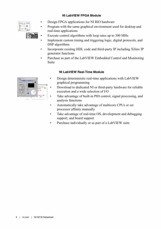
NI LabVIEW FPGA Module
• Design FPGA applications for NI RIO hardware• Program with the same graphical environment used for desktop and
real-time applications• Execute control algorithms with loop rates up to 300 MHz• Implement custom timing and triggering logic, digital protocols, and
DSP algorithms• Incorporate existing HDL code and third-party IP including Xilinx IP
generator functions• Purchase as part of the LabVIEW Embedded Control and Monitoring
Suite
NI LabVIEW Real-Time Module
• Design deterministic real-time applications with LabVIEWgraphical programming
• Download to dedicated NI or third-party hardware for reliableexecution and a wide selection of I/O
• Take advantage of built-in PID control, signal processing, andanalysis functions
• Automatically take advantage of multicore CPUs or setprocessor affinity manually
• Take advantage of real-time OS, development and debuggingsupport, and board support
• Purchase individually or as part of a LabVIEW suite
4 | ni.com | NI 9218 Datasheet

NI 9218 Circuitry
CH0
Isolation
Isolation
Vsup
NI 9218
Inpu
tC
onne
ctor
P
ower
Con
nect
or
ExternalPower Supply
Measurement TypeSignal Conditioning
12 VExcitation
IsolatorADC
CH1
Inpu
tC
onne
ctor
Measurement TypeSignal Conditioning
12 VExcitation
IsolatorADC
Hardware ComponentsSoftware-SelectableExternally Supplied Voltage
Legend
Data
• Two 24-bit analog-to-digital converters (ADCs) simultaneously sample both AI channels.• The NI 9218 provides channel-to-channel isolation.• The NI 9218 reconfigures the signal conditioning for each measurement type.• The NI 9218 provides excitation for IEPE and bridge completion measurement types.• The NI 9218 can provide optional 12 V sensor excitation for ±16 V, ±65 mV, and ±20 mA
measurement types.
±16 V and ±65 mV Signal Conditioning
AI+
AI-ADC
Amplifier
OvervoltageProtection
PrefilterNI 9218
Input signals on each channel are buffered, conditioned, and then sampled by an ADC.
NI 9218 Datasheet | © National Instruments | 5

Full-Bridge Signal Conditioning
+ –
Reference
InputAI+
EX+
RS+
AI–
EX–
RS–
SC
SC
NI 9218
ADC
• The analog input connections sense then amplify the incoming analog signal.• The excitation connections provide differential bridge-excitation voltage.• Remote sensing continuously and automatically corrects for lead-wire induced excitation
voltage loss when using the RS connections.• Shunt calibration can be used to correct for lead-wire induced desensitization of the
bridge.
IEPE Signal Conditioning
2 mAIEPE
Amplifierand
Prefilter
AC Coupling
NI 9218
+
–ADC
AI+
AI-
• The incoming analog signal is referenced to an isolated ground.• Each channel is configured for AC coupling with an IEPE current.• Each channel provides a TEDS Class 1 interface.
6 | ni.com | NI 9218 Datasheet

±20 mA Signal Conditioning
AI+
DS
UB
/LE
MO
AI-ADC
Amplifier
OvervoltageProtection
CurrentShunt
PrefilterNI 9218
The NI 9983 provides a current shunt for the incoming analog signal.
±60 V Signal Conditioning
AI+
DS
UB
/LE
MO
AI-ADC
Amplifier
OvervoltageProtection
PrefilterNI 9218
The NI 9987 provides an attenuator for the incoming analog signal.
Half-Bridge Signal Conditioning
+ –
Reference
Input
NI 9218
ADC
DS
UB
/LE
MO
AI+
EX+
RS+
EX–
RS–
SC
SC
• The NI 9886 provides half bridge completion resistors for the incoming analog signal.• You must connect AI+, EX+, and EX-.• RS+ and RS- connections are optional.• You do not need to connect the AI- signal because it is connected internally.
NI 9218 Datasheet | © National Instruments | 7
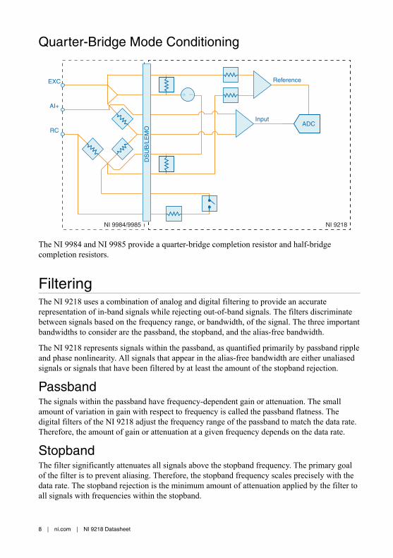
Quarter-Bridge Mode Conditioning
+ –
Reference
Input
NI 9218NI 9984/9985
ADC
DS
UB
/LE
MO
AI+
EXC
RC
The NI 9984 and NI 9985 provide a quarter-bridge completion resistor and half-bridgecompletion resistors.
FilteringThe NI 9218 uses a combination of analog and digital filtering to provide an accuraterepresentation of in-band signals while rejecting out-of-band signals. The filters discriminatebetween signals based on the frequency range, or bandwidth, of the signal. The three importantbandwidths to consider are the passband, the stopband, and the alias-free bandwidth.
The NI 9218 represents signals within the passband, as quantified primarily by passband rippleand phase nonlinearity. All signals that appear in the alias-free bandwidth are either unaliasedsignals or signals that have been filtered by at least the amount of the stopband rejection.
PassbandThe signals within the passband have frequency-dependent gain or attenuation. The smallamount of variation in gain with respect to frequency is called the passband flatness. Thedigital filters of the NI 9218 adjust the frequency range of the passband to match the data rate.Therefore, the amount of gain or attenuation at a given frequency depends on the data rate.
StopbandThe filter significantly attenuates all signals above the stopband frequency. The primary goalof the filter is to prevent aliasing. Therefore, the stopband frequency scales precisely with thedata rate. The stopband rejection is the minimum amount of attenuation applied by the filter toall signals with frequencies within the stopband.
8 | ni.com | NI 9218 Datasheet

Alias-Free BandwidthAny signal that appears in the alias-free bandwidth of the NI 9218 is not an aliased artifact ofsignals at a higher frequency. The alias-free bandwidth is defined by the ability of the filter toreject frequencies above the stopband frequency, and it is equal to the data rate minus thestopband frequency.
NI 9218 SpecificationsThe following specifications are typical for the range -40 °C to 70 °C unless otherwise noted.
Caution Do not operate the NI 9218 in a manner not specified in this document.Product misuse can result in a hazard. You can compromise the safety protectionbuilt into the product if the product is damaged in any way. If the product isdamaged, return it to NI for repair.
General CharacteristicsNumber of channels 2 analog input channels
ADC resolution 24 bits
Type of ADC Delta-Sigma
Sampling mode Simultaneous
TEDS support
NI 9218 with DSUB IEEE 1451.4 TEDS Class 1
NI 9218 with LEMO IEEE 1451.4 TEDS Class 1 and TEDS Class 2
Internal master timebase (fM)
Frequency 13.1072 MHz
Accuracy 100 ppm
Figure 1. Data Rates÷ 256 , = 1, 2, ..., 31Data rate range (fs) using internal master timebase
Minimum 1.652 kS/s
Maximum 51.2 kS/s
Data rate range (fs) using external master timebase
Minimum 1 kS/s
Maximum 51.367 kS/s
NI 9218 Datasheet | © National Instruments | 9
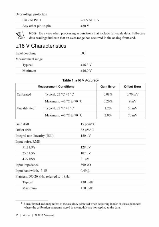
Overvoltage protection
Pin 2 to Pin 3 -20 V to 30 V
Any other pin-to-pin ±30 V
Note Be aware when processing acquisitions that include full-scale data. Full-scaledata readings indicate that an over-range has occurred in the analog front-end.
±16 V CharacteristicsInput coupling DC
Measurement range
Typical ±16.3 V
Minimum ±16.0 V
Table 1. ±16 V Accuracy
Measurement Conditions Gain Error Offset Error
Calibrated Typical, 23 °C ±5 °C 0.08% 0.70 mV
Maximum, -40 °C to 70 °C 0.20% 9 mV
Uncalibrated1 Typical, 23 °C ±5 °C 1.2% 50 mV
Maximum, -40 °C to 70 °C 2.0% 70 mV
Gain drift 15 ppm/°C
Offset drift 32 μV/°C
Integral non-linearity (INL) 150 μV
Input noise, RMS
51.2 kS/s 128 μV
25.6 kS/s 107 μV
4.27 kS/s 81 μV
Input impedance 390 kΩ
Input bandwidth, -3 dB 0.49 fsFlatness, DC-20 kHz, referred to 1 kHz
Typical ±30 mdB
Maximum ±50 mdB
1 Uncalibrated accuracy refers to the accuracy achieved when acquiring in raw or unscaled modeswhere the calibration constants stored in the module are not applied to the data.
10 | ni.com | NI 9218 Datasheet

Phase non-linearity, DC-20 kHz 0.30°
Input delay (40 + [5/512])/fs + 5.3 μs
Stopband
Frequency 0.55 fsRejection 100 dB
Alias-free bandwidth 0.45 fsOversample rate 64 fsRejection at oversample rate(fs = 51.2 kS/s)
100 dB
Total Harmonic Distortion (THD),1 kHz, -1 dBFS
-100 dBc
Spurious-Free Dynamic Range (SFDR),1 kHz, 1 Vrms
101 dB
Crosstalk
60 Hz, 1 Vrms, common mode -120 dBFS
1 kHz normal mode, full-scaleaggressor
-109 dBFS
CMRR, 60 Hz 1 Vrms-to-earth ground -120 dBFS
Powered sensor 12 V excitation
Voltage level 12 V ±5%
Voltage noise, RMS100 kHz bandwidth
1 mV
Output current
Typical 50.5 mA
Minimum 46.5 mA
Settling Time (to 1 % of final valueafter enabling)
200 ms
Related InformationVsup Power Requirements on page 25
±65 mV CharacteristicsInput coupling DC
NI 9218 Datasheet | © National Instruments | 11
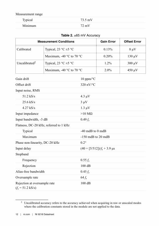
Measurement range
Typical 73.5 mV
Minimum 72 mV
Table 2. ±65 mV Accuracy
Measurement Conditions Gain Error Offset Error
Calibrated Typical, 23 °C ±5 °C 0.13% 8 μV
Maximum, -40 °C to 70 °C 0.20% 130 μV
Uncalibrated2 Typical, 23 °C ±5 °C 1.2% 300 μV
Maximum, -40 °C to 70 °C 2.0% 450 μV
Gain drift 10 ppm/°C
Offset drift 320 nV/°C
Input noise, RMS
51.2 kS/s 4.3 μV
25.6 kS/s 3 μV
4.27 kS/s 1.3 μV
Input impedance >10 MΩ
Input bandwidth, -3 dB 0.49 fsFlatness, DC-20 kHz, referred to 1 kHz
Typical -40 mdB to 0 mdB
Maximum -150 mdB to 20 mdB
Phase non-linearity, DC-20 kHz 0.2°
Input delay (40 + [5/512])/fs + 3.9 μs
Stopband
Frequency 0.55 fsRejection 100 dB
Alias-free bandwidth 0.45 fsOversample rate 64 fsRejection at oversample rate(fs = 51.2 kS/s)
100 dB
2 Uncalibrated accuracy refers to the accuracy achieved when acquiring in raw or unscaled modeswhere the calibration constants stored in the module are not applied to the data.
12 | ni.com | NI 9218 Datasheet
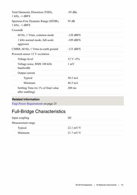
Total Harmonic Distortion (THD),1 kHz, -1 dBFS
-95 dBc
Spurious-Free Dynamic Range (SFDR),1 kHz, -1 dBFS
95 dB
Crosstalk
60 Hz, 1 Vrms, common mode -120 dBFS
1 kHz normal mode, full-scaleaggressor
-109 dBFS
CMRR, 60 Hz, 1 Vrms-to-earth ground -133 dBFS
Powered sensor 12 V excitation
Voltage level 12 V ±5%
Voltage noise, RMS 100 kHzbandwidth
1 mV
Output current
Typical 50.5 mA
Minimum 46.5 mA
Settling Time (to 1% of final valueafter enabling)
200 ms
Related InformationVsup Power Requirements on page 25
Full-Bridge CharacteristicsInput coupling DC
Measurement range
Typical 22.1 mV/V
Minimum 21.7 mV/V
NI 9218 Datasheet | © National Instruments | 13

Table 3. Full-Bridge Accuracy
Measurement Conditions Gain
Offset
WithoutOffset Null
≤ 90 days,±5 °C fromOffset Null
Calibrated 3.3 V Excitation Typical, 23 °C±5 °C
0.10% 2.4 μV/V 0.5 μV/V
Maximum -40 °Cto 70 °C
0.20% 40 μV/V 5 μV/V
2 V Excitation Typical, 23 °C±5 °C
0.10% 30 μV /V 0.8 μV/V
Maximum -40 °Cto 70 °C
0.20% 87 μV/V 8 μV/V
Uncalibrated3 3.3 V Excitation Typical, 23 °C±5 °C
1.2% 100 μV/V —
Maximum -40 °Cto 70 °C
2.0% 150 μV/V —
2 V Excitation Typical, 23 °C±5 °C
1.2% 120 μV/V —
Maximum -40 °Cto 70 °C
2.0% 200 μV/V —
Gain drift 10 ppm/°C
Offset drift
3.3 V excitation 100 nV/V/°C
2 V excitation 160 nV/V/°C
3 Uncalibrated accuracy refers to the accuracy achieved when acquiring in raw or unscaled modeswhere the calibration constants stored in the module are not applied to the data.
14 | ni.com | NI 9218 Datasheet

Table 4. Input Noise, RMS
Excitation Voltage Sample Rate
4.27 kS/s 25.6 kS/s 51.2 kS/s
3.3 V 0.4 μV/V 1.0 μV/V 1.3 μV/V
2 V 0.7 μV/V 1.6 μV/V 2.1 μV/V
Differential input impedance >10 MΩ
Input bandwidth, -3 dB 0.49 fsFlatness, DC-20 kHz, referred to 1 kHz
Typical -40 mdB to 0 mdB
Maximum -150 mdB to 20 mdB
Phase non-linearity, DC-20 kHz 0.2°
Input delay (40 + [5/512])/fs + 3.9 μs
Stopband
Frequency 0.55 fsRejection 100 dB
Alias-free bandwidth 0.45 fsOversample rate 64 fsRejection at oversample rate(fs = 51.2 kS/s)
100 dB
Total Harmonic Distortion (THD), 1 kHz,-1 dBFS
-95 dBc
Spurious-Free Dynamic Range (SFDR),1 kHz, -1 dBFS
95 dB
Crosstalk
60 Hz, 1 Vrms, common mode -120 dBFS
1 kHz, normal mode, full-scaleaggressor
-109 dBFS
CMRR, 60 Hz, 1 Vrms-to-earth ground -133 dBFS
Shunt calibration accuracy 50 kΩ ±0.2%
Strain excitation voltage
2 V level 2 V ±3%
3.3 V level 3.3 V ±3%
NI 9218 Datasheet | © National Instruments | 15
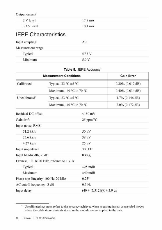
Output current
2 V level 17.8 mA
3.3 V level 10.1 mA
IEPE CharacteristicsInput coupling AC
Measurement range
Typical 5.33 V
Minimum 5.0 V
Table 5. IEPE Accuracy
Measurement Conditions Gain Error
Calibrated Typical, 23 °C ±5 °C 0.20% (0.017 dB)
Maximum, -40 °C to 70 °C 0.40% (0.034 dB)
Uncalibrated4 Typical, 23 °C ±5 °C 1.7% (0.146 dB)
Maximum, -40 °C to 70 °C 2.0% (0.172 dB)
Residual DC offset <150 mV
Gain drift 25 ppm/°C
Input noise, RMS
51.2 kS/s 50 μV
25.6 kS/s 38 μV
4.27 kS/s 25 μV
Input impedance 300 kΩ
Input bandwidth, -3 dB 0.49 fsFlatness, 10 Hz-20 kHz, referred to 1 kHz
Typical ±25 mdB
Maximum ±40 mdB
Phase non-linearity, 100 Hz-20 kHz 0.25°
AC cutoff frequency, -3 dB 0.5 Hz
Input delay (40 + [5/512])/fs + 3.9 μs
4 Uncalibrated accuracy refers to the accuracy achieved when acquiring in raw or unscaled modeswhere the calibration constants stored in the module are not applied to the data.
16 | ni.com | NI 9218 Datasheet
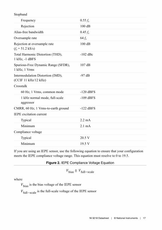
Stopband
Frequency 0.55 fsRejection 100 dB
Alias-free bandwidth 0.45 fsOversample rate 64 fsRejection at oversample rate(fs = 51.2 kS/s)
100 dB
Total Harmonic Distortion (THD),1 kHz, -1 dBFS
-102 dBc
Spurious-Free Dynamic Range (SFDR),1 kHz, 1 Vrms
107 dB
Intermodulation Distortion (IMD),(CCIF 11 kHz/12 kHz)
-97 dB
Crosstalk
60 Hz, 1 Vrms, common mode -120 dBFS
1 kHz normal mode, full-scaleaggressor
-109 dBFS
CMRR, 60 Hz, 1 Vrms-to-earth ground -122 dBFS
IEPE excitation current
Typical 2.2 mA
Minimum 2.1 mA
Compliance voltage
Typical 20.5 V
Minimum 19.5 V
If you are using an IEPE sensor, use the following equation to ensure that your configurationmeets the IEPE compliance voltage range. This equation must resolve to 0 to 19.5.
Figure 2. IEPE Compliance Voltage Equationbias± full−scalewherebias is the bias voltage of the IEPE sensorfull−scale is the full-scale voltage of the IEPE sensor
NI 9218 Datasheet | © National Instruments | 17

±20 mA CharacteristicsThe ±20 mA measurement type requires the NI 9983 measurement-specific adapter. Thecharacteristics are for the NI 9218 used in conjunction with the NI 9983.
Input coupling DC
Measurement range
Typical 24.4 mA
Minimum 23.0 mA
Table 6. ±20 mA Accuracy
Measurement Conditions Gain Error Offset Error
Calibrated Typical, 23 °C ±5 °C 0.40% 5 μA
Maximum, -40 °C to 70 °C 0.60% 42 μA
Uncalibrated5 Typical, 23 °C ±5 °C 1.5% 100 μA
Maximum, -40 °C to 70 °C 2.0% 150 μA
Gain drift 35 ppm/°C
Offset drift 105 nA/°C
Shunt resistance 3.01 Ω
Input noise, RMS
51.2 kS/s 1.4 μA
25.6 kS/s 1.0 μA
4.27 kS/s 0.5 μA
Input impedance 45 Ω ±30%
Input bandwidth, -3 dB 0.49 fsInput delay (40 + [5/512])/fs + 3.9 μs
Stopband
Frequency 0.55 fsRejection 100 dB
Alias-free bandwidth 0.45 fsOversample rate 64 fs
5 Uncalibrated accuracy refers to the accuracy achieved when acquiring in raw or unscaled modeswhere the calibration constants stored in the module are not applied to the data.
18 | ni.com | NI 9218 Datasheet

Rejection at oversample rate(fs = 51.2 kS/s)
100 dB
Crosstalk
60 Hz, 1 Vrms, common mode -120 dBFS
1 kHz normal mode, full-scaleaggressor
-109 dBFS
CMRR, 60 Hz, 1 Vrms-to-earth ground -99 dBFS
Powered sensor 12 V excitation
Voltage level 12 V ±5%
Voltage noise, RMS,100 kHz bandwidth
1 mV
Output current
Typical 50.5 mA
Minimum 46.5 mA
Settling Time (to 1% of final valueafter enabling)
200 ms
Related InformationVsup Power Requirements on page 25
±60 V CharacteristicsThe ±60 V measurement type requires the NI 9987 measurement-specific adapter. Thecharacteristics are for the NI 9218 used in conjunction with the NI 9987.
Input coupling DC
Measurement range
Typical ±62.1 V
Minimum ±60 V
Table 7. ±60 V Accuracy
Measurement Conditions Gain Error Offset Error
Calibrated Typical, 23 °C ±5 °C 0.3% 3 mV
Maximum, -40 °C to 70 °C 0.6% 40 mV
NI 9218 Datasheet | © National Instruments | 19
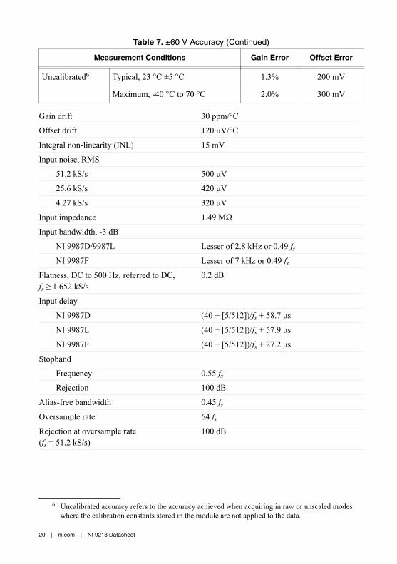
Table 7. ±60 V Accuracy (Continued)
Measurement Conditions Gain Error Offset Error
Uncalibrated6 Typical, 23 °C ±5 °C 1.3% 200 mV
Maximum, -40 °C to 70 °C 2.0% 300 mV
Gain drift 30 ppm/°C
Offset drift 120 μV/°C
Integral non-linearity (INL) 15 mV
Input noise, RMS
51.2 kS/s 500 μV
25.6 kS/s 420 μV
4.27 kS/s 320 μV
Input impedance 1.49 MΩ
Input bandwidth, -3 dB
NI 9987D/9987L Lesser of 2.8 kHz or 0.49 fsNI 9987F Lesser of 7 kHz or 0.49 fs
Flatness, DC to 500 Hz, referred to DC,fs ≥ 1.652 kS/s
0.2 dB
Input delay
NI 9987D (40 + [5/512])/fs + 58.7 μs
NI 9987L (40 + [5/512])/fs + 57.9 μs
NI 9987F (40 + [5/512])/fs + 27.2 μs
Stopband
Frequency 0.55 fsRejection 100 dB
Alias-free bandwidth 0.45 fsOversample rate 64 fsRejection at oversample rate(fs = 51.2 kS/s)
100 dB
6 Uncalibrated accuracy refers to the accuracy achieved when acquiring in raw or unscaled modeswhere the calibration constants stored in the module are not applied to the data.
20 | ni.com | NI 9218 Datasheet
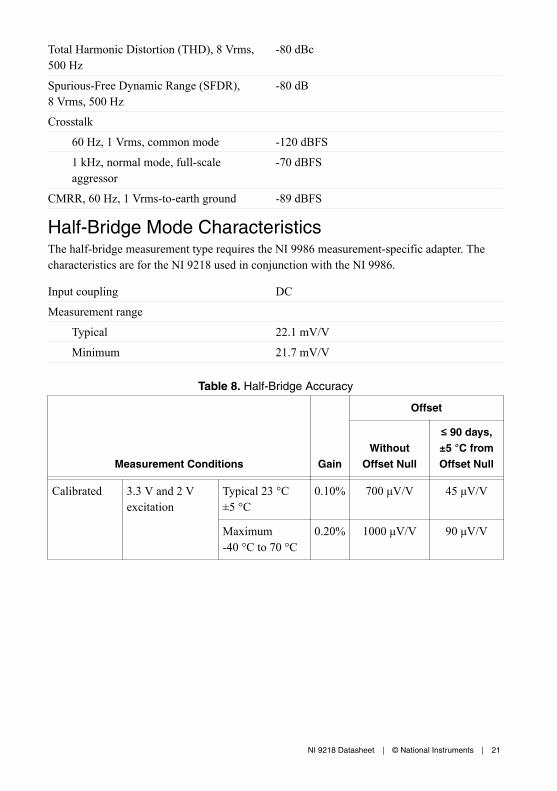
Total Harmonic Distortion (THD), 8 Vrms,500 Hz
-80 dBc
Spurious-Free Dynamic Range (SFDR),8 Vrms, 500 Hz
-80 dB
Crosstalk
60 Hz, 1 Vrms, common mode -120 dBFS
1 kHz, normal mode, full-scaleaggressor
-70 dBFS
CMRR, 60 Hz, 1 Vrms-to-earth ground -89 dBFS
Half-Bridge Mode CharacteristicsThe half-bridge measurement type requires the NI 9986 measurement-specific adapter. Thecharacteristics are for the NI 9218 used in conjunction with the NI 9986.
Input coupling DC
Measurement range
Typical 22.1 mV/V
Minimum 21.7 mV/V
Table 8. Half-Bridge Accuracy
Measurement Conditions Gain
Offset
WithoutOffset Null
≤ 90 days,±5 °C fromOffset Null
Calibrated 3.3 V and 2 Vexcitation
Typical 23 °C±5 °C
0.10% 700 μV/V 45 μV/V
Maximum-40 °C to 70 °C
0.20% 1000 μV/V 90 μV/V
NI 9218 Datasheet | © National Instruments | 21

Table 8. Half-Bridge Accuracy (Continued)
Measurement Conditions Gain
Offset
WithoutOffset Null
≤ 90 days,±5 °C fromOffset Null
Uncalibrated7 3.3 V and 2 Vexcitation
Typical 23 °C±5 °C
1.2% 800 μV/V —
Maximum-40 °C to 70 °C
2.0% 1.1 mV/V —
Gain drift 10 ppm/°C
Offset drift 1.3 μV/V/°C
Table 9. Input Noise, RMS
Excitation Voltage Sample Rate
4.27 kS/s 25.6 kS/s 51.2 kS/s
3.3 V 0.4 μV/V 1.0 μV/V 1.3 μV/V
2 V 0.7 μV/V 1.6 μV/V 2.2 μV/V
Input bandwidth, -3 dB 0.49 fsFlatness, DC-20 kHz, referred to 1 kHz
Typical -40 mdB to 0 mdB
Maximum -150 mdB to 20 mdB
Phase non-linearity, DC-20 kHz 0.2°
Input delay (40 + [5/512])/fs + 3.9 μs
Stopband
Frequency 0.55 fsRejection 100 dB
Alias-free bandwidth 0.45 fsOversample rate 64 fs
7 Uncalibrated accuracy refers to the accuracy achieved when acquiring in raw or unscaled modeswhere the calibration constants stored in the module are not applied to the data.
22 | ni.com | NI 9218 Datasheet

Rejection at oversample rate(fs = 51.2 kS/s)
100 dB
Total Harmonic Distortion (THD), 1 kHz,-1 dBFS
-95 dBc
Spurious-Free Dynamic Range (SFDR),1 kHz, -1 dBFS
95 dB
Crosstalk
60 Hz, 1 Vrms, common mode -120 dBFS
1 kHz, normal mode, full-scaleaggressor
-85 dBFS
CMRR, 60 Hz, 1 Vrms-to-earth ground -73 dBFS
Strain excitation voltage
2 V level 2 V ±3%
3.3 V level 3.3 V ±3%
Output current
2 V level 17.8 mA
3.3 V level 10.1 mA
Quarter-Bridge CharacteristicsThe quarter-bridge measurement type requires the NI 9984 or NI 9985 measurement-specificadapter. The characteristics are for the NI 9218 used in conjunction with the NI 9984 or theNI 9985.
Input coupling DC
Measurement range
Typical 22.1 mV/V
Minimum 21.7 mV/V
NI 9218 Datasheet | © National Instruments | 23
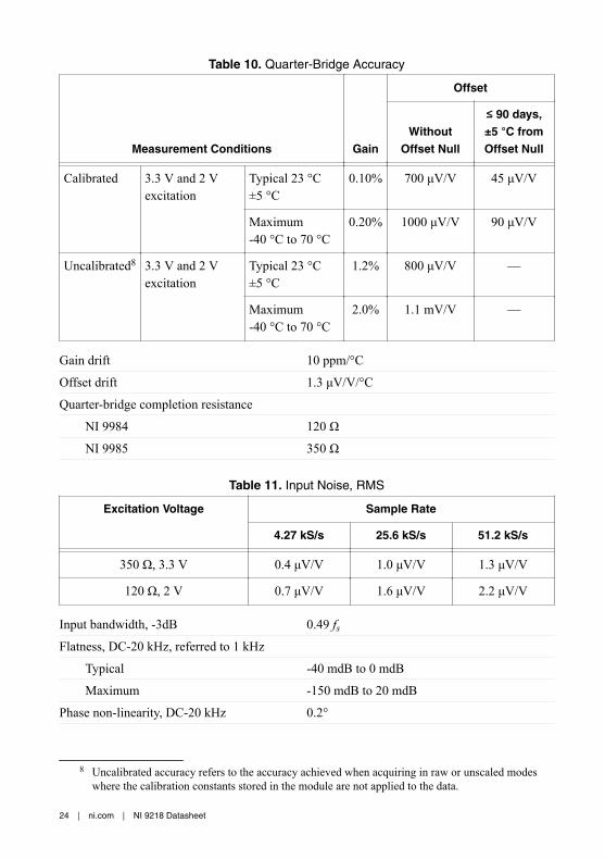
Table 10. Quarter-Bridge Accuracy
Measurement Conditions Gain
Offset
WithoutOffset Null
≤ 90 days,±5 °C fromOffset Null
Calibrated 3.3 V and 2 Vexcitation
Typical 23 °C±5 °C
0.10% 700 μV/V 45 μV/V
Maximum-40 °C to 70 °C
0.20% 1000 μV/V 90 μV/V
Uncalibrated8 3.3 V and 2 Vexcitation
Typical 23 °C±5 °C
1.2% 800 μV/V —
Maximum-40 °C to 70 °C
2.0% 1.1 mV/V —
Gain drift 10 ppm/°C
Offset drift 1.3 μV/V/°C
Quarter-bridge completion resistance
NI 9984 120 Ω
NI 9985 350 Ω
Table 11. Input Noise, RMS
Excitation Voltage Sample Rate
4.27 kS/s 25.6 kS/s 51.2 kS/s
350 Ω, 3.3 V 0.4 μV/V 1.0 μV/V 1.3 μV/V
120 Ω, 2 V 0.7 μV/V 1.6 μV/V 2.2 μV/V
Input bandwidth, -3dB 0.49 fsFlatness, DC-20 kHz, referred to 1 kHz
Typical -40 mdB to 0 mdB
Maximum -150 mdB to 20 mdB
Phase non-linearity, DC-20 kHz 0.2°
8 Uncalibrated accuracy refers to the accuracy achieved when acquiring in raw or unscaled modeswhere the calibration constants stored in the module are not applied to the data.
24 | ni.com | NI 9218 Datasheet
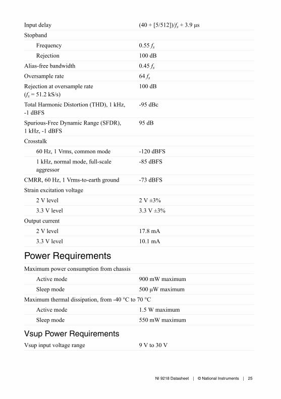
Input delay (40 + [5/512])/fs + 3.9 μs
Stopband
Frequency 0.55 fsRejection 100 dB
Alias-free bandwidth 0.45 fsOversample rate 64 fsRejection at oversample rate(fs = 51.2 kS/s)
100 dB
Total Harmonic Distortion (THD), 1 kHz,-1 dBFS
-95 dBc
Spurious-Free Dynamic Range (SFDR),1 kHz, -1 dBFS
95 dB
Crosstalk
60 Hz, 1 Vrms, common mode -120 dBFS
1 kHz, normal mode, full-scaleaggressor
-85 dBFS
CMRR, 60 Hz, 1 Vrms-to-earth ground -73 dBFS
Strain excitation voltage
2 V level 2 V ±3%
3.3 V level 3.3 V ±3%
Output current
2 V level 17.8 mA
3.3 V level 10.1 mA
Power RequirementsMaximum power consumption from chassis
Active mode 900 mW maximum
Sleep mode 500 μW maximum
Maximum thermal dissipation, from -40 °C to 70 °C
Active mode 1.5 W maximum
Sleep mode 550 mW maximum
Vsup Power RequirementsVsup input voltage range 9 V to 30 V
NI 9218 Datasheet | © National Instruments | 25

Maximum power consumption from Vsup
Active mode 2 W maximum
Sleep mode 400 mW maximum
Physical CharacteristicsIf you need to clean the module, wipe it with a dry towel.
Tip For two-dimensional drawings and three-dimensional models of the C Seriesmodule and connectors, visit ni.com/dimensions and search by module number.
Weight
NI 9218 with DSUB 151 g (5.33 oz)
NI 9218 with LEMO 165 g (5.82 oz)
NI 998x Physical CharacteristicsScrew-terminal wiring
Gauge 0.05 mm2 (30 AWG) to 1.31 mm2 (16 AWG)copper conductor wire
Wire strip length 6 mm (0.236 in.) of insulation stripped fromthe end
Temperature rating 80 °C minimum
Wires per screw terminal One or two wires per screw terminal
Ferrules, single wire 0.25 mm2 (20 AWG) to 0.52 mm2 (24 AWG)
Torque for screw terminals 0.2 N · m to 0.25 N · m (1.77 lb · in. to2.21 lb · in.)
Wire securement
NI 998xD, NI 998xL securement type Three collets provided(ranging from 2.2 mm to 5.2 mm in diameter)
Torque for collet nut 1.5 N · m (13.3 lb · in.)
NI 998xF securement type Zip tie provided
NI 998xD and NI 998xF connector securement
Securement type Jackscrews provided
Jackscrew torque 0.4 N · m (3.6 in · lb)
Weight
NI 998xD, NI 998xL 142 g (5.0 oz) with cable
NI 998xF 34 g (1.2 oz)
26 | ni.com | NI 9218 Datasheet
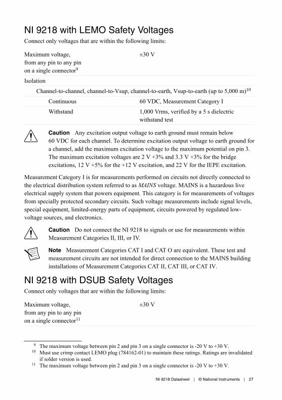
NI 9218 with LEMO Safety VoltagesConnect only voltages that are within the following limits:
Maximum voltage,from any pin to any pinon a single connector9
±30 V
Isolation
Channel-to-channel, channel-to-Vsup, channel-to-earth, Vsup-to-earth (up to 5,000 m)10
Continuous 60 VDC, Measurement Category I
Withstand 1,000 Vrms, verified by a 5 s dielectricwithstand test
Caution Any excitation output voltage to earth ground must remain below60 VDC for each channel. To determine excitation output voltage to earth ground fora channel, add the maximum excitation voltage to the maximum potential on pin 3.The maximum excitation voltages are 2 V +3% and 3.3 V +3% for the bridgeexcitations, 12 V +5% for the +12 V excitation, and 22 V for the IEPE excitation.
Measurement Category I is for measurements performed on circuits not directly connected tothe electrical distribution system referred to as MAINS voltage. MAINS is a hazardous liveelectrical supply system that powers equipment. This category is for measurements of voltagesfrom specially protected secondary circuits. Such voltage measurements include signal levels,special equipment, limited-energy parts of equipment, circuits powered by regulated low-voltage sources, and electronics.
Caution Do not connect the NI 9218 to signals or use for measurements withinMeasurement Categories II, III, or IV.
Note Measurement Categories CAT I and CAT O are equivalent. These test andmeasurement circuits are not intended for direct connection to the MAINS buildinginstallations of Measurement Categories CAT II, CAT III, or CAT IV.
NI 9218 with DSUB Safety VoltagesConnect only voltages that are within the following limits:
Maximum voltage,from any pin to any pinon a single connector11
±30 V
9 The maximum voltage between pin 2 and pin 3 on a single connector is -20 V to +30 V.10 Must use crimp contact LEMO plug (784162-01) to maintain these ratings. Ratings are invalidated
if solder version is used.11 The maximum voltage between pin 2 and pin 3 on a single connector is -20 V to +30 V.
NI 9218 Datasheet | © National Instruments | 27

Isolation
Channel-to-channel, channel-to-Vsup inputs (up to 5,000 m)
Continuous 60 VDC, Measurement Category I
Withstand 1,000 Vrms, verified by a 5 s dielectricwithstand test
Channel-to-earth ground (up to 3,000 m)
Continuous 60 VDC, Measurement Category I
Withstand 1,000 Vrms, verified by a 5 s dielectricwithstand test
Channel-to-earth ground (up to 5,000 m)
Continuous 60 VDC, Measurement Category I
Withstand 860 Vrms
Vsup inputs-to-earth ground (up to 5,000 m)
Continuous 60 VDC, Measurement Category I
Withstand 1,000 Vrms, verified by a 5 s dielectricwithstand test
Caution Any excitation output voltage to earth ground must remain below 60VDC for each channel. To determine excitation output voltage to earth ground for achannel, add the maximum excitation voltage to the maximum potential on pin 3.The maximum excitation voltages are 2 V +3% and 3.3 V +3% for the bridgeexcitations, 12 V +5% for the +12 V excitation, and 22 V for the IEPE excitation.
Measurement Category I is for measurements performed on circuits not directly connected tothe electrical distribution system referred to as MAINS voltage. MAINS is a hazardous liveelectrical supply system that powers equipment. This category is for measurements of voltagesfrom specially protected secondary circuits. Such voltage measurements include signal levels,special equipment, limited-energy parts of equipment, circuits powered by regulated low-voltage sources, and electronics.
Caution Do not connect the NI 9218 to signals or use for measurements withinMeasurement Categories II, III, or IV.
Note Measurement Categories CAT I and CAT O are equivalent. These test andmeasurement circuits are not intended for direct connection to the MAINS buildinginstallations of Measurement Categories CAT II, CAT III, or CAT IV.
28 | ni.com | NI 9218 Datasheet
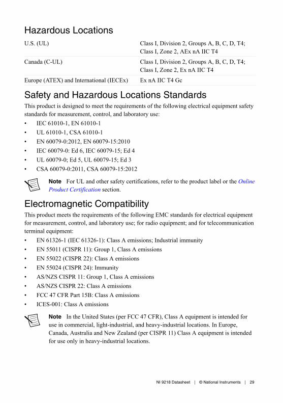
Hazardous LocationsU.S. (UL) Class I, Division 2, Groups A, B, C, D, T4;
Class I, Zone 2, AEx nA IIC T4
Canada (C-UL) Class I, Division 2, Groups A, B, C, D, T4;Class I, Zone 2, Ex nA IIC T4
Europe (ATEX) and International (IECEx) Ex nA IIC T4 Gc
Safety and Hazardous Locations StandardsThis product is designed to meet the requirements of the following electrical equipment safetystandards for measurement, control, and laboratory use:• IEC 61010-1, EN 61010-1• UL 61010-1, CSA 61010-1• EN 60079-0:2012, EN 60079-15:2010• IEC 60079-0: Ed 6, IEC 60079-15; Ed 4• UL 60079-0; Ed 5, UL 60079-15; Ed 3• CSA 60079-0:2011, CSA 60079-15:2012
Note For UL and other safety certifications, refer to the product label or the OnlineProduct Certification section.
Electromagnetic CompatibilityThis product meets the requirements of the following EMC standards for electrical equipmentfor measurement, control, and laboratory use; for radio equipment; and for telecommunicationterminal equipment:• EN 61326-1 (IEC 61326-1): Class A emissions; Industrial immunity• EN 55011 (CISPR 11): Group 1, Class A emissions• EN 55022 (CISPR 22): Class A emissions• EN 55024 (CISPR 24): Immunity• AS/NZS CISPR 11: Group 1, Class A emissions• AS/NZS CISPR 22: Class A emissions• FCC 47 CFR Part 15B: Class A emissions• ICES-001: Class A emissions
Note In the United States (per FCC 47 CFR), Class A equipment is intended foruse in commercial, light-industrial, and heavy-industrial locations. In Europe,Canada, Australia and New Zealand (per CISPR 11) Class A equipment is intendedfor use only in heavy-industrial locations.
NI 9218 Datasheet | © National Instruments | 29

Note Group 1 equipment (per CISPR 11) is any industrial, scientific, or medicalequipment that does not intentionally generate radio frequency energy for thetreatment of material or inspection/analysis purposes.
Note For EMC declarations and certifications, and additional information, refer tothe Online Product Certification section.
CE Compliance This product meets the essential requirements of applicable European Directives, as follows:• 2014/35/EU; Low-Voltage Directive (safety)• 2014/30/EU; Electromagnetic Compatibility Directive (EMC)• 94/9/EC; Potentially Explosive Atmospheres (ATEX)
Shock and VibrationTo meet these specifications, you must panel mount the system.
Operating vibration
Random (IEC 60068-2-64) 5 grms, 10 Hz to 500 Hz
Sinusoidal (IEC 60068-2-6) 5 g, 10 Hz to 500 Hz
Operating shock (IEC 60068-2-27) 30 g, 11 ms half sine; 50 g, 3 ms half sine;18 shocks at 6 orientations
Online Product CertificationRefer to the product Declaration of Conformity (DoC) for additional regulatory complianceinformation. To obtain product certifications and the DoC for this product, visit ni.com/certification, search by model number or product line, and click the appropriate link in theCertification column.
EnvironmentalRefer to the manual for the chassis you are using for more information about meeting thesespecifications.
Operating temperature(IEC 60068-2-1, IEC 60068-2-2)
-40 °C to 70 °C
Storage temperature(IEC 60068-2-1, IEC 60068-2-2)
-40 °C to 85 °C
Ingress protection IP40
Operating humidity (IEC 60068-2-78) 10% RH to 90% RH, noncondensing
Storage humidity (IEC 60068-2-78) 5% RH to 95% RH, noncondensing
30 | ni.com | NI 9218 Datasheet

Pollution Degree 2
Maximum altitude 5,000 m
Indoor use only.
NI 998x EnvironmentalOperating temperature (IEC 60068-2-1) -40 °C to 70 °C
Environmental ManagementNI is committed to designing and manufacturing products in an environmentally responsiblemanner. NI recognizes that eliminating certain hazardous substances from our products isbeneficial to the environment and to NI customers.
For additional environmental information, refer to the Minimize Our Environmental Impactweb page at ni.com/environment. This page contains the environmental regulations anddirectives with which NI complies, as well as other environmental information not included inthis document.
Waste Electrical and Electronic Equipment (WEEE)EU Customers At the end of the product life cycle, all NI products must bedisposed of according to local laws and regulations. For more information abouthow to recycle NI products in your region, visit ni.com/environment/weee.
电子信息产品污染控制管理办法(中国 RoHS)中国客户 National Instruments 符合中国电子信息产品中限制使用某些有害物
质指令(RoHS)。关于 National Instruments 中国 RoHS 合规性信息,请登录
ni.com/environment/rohs_china。(For information about China RoHScompliance, go to ni.com/environment/rohs_china.)
CalibrationYou can obtain the calibration certificate and information about calibration services for theNI 9218 at ni.com/calibration.
Calibration interval 2 years
NI 9218 Datasheet | © National Instruments | 31

Refer to the NI Trademarks and Logo Guidelines at ni.com/trademarks for information on NI trademarks. Other product andcompany names mentioned herein are trademarks or trade names of their respective companies. For patents covering NIproducts/technology, refer to the appropriate location: Help»Patents in your software, the patents.txt file on your media, or theNational Instruments Patent Notice at ni.com/patents. You can find information about end-user license agreements (EULAs)and third-party legal notices in the readme file for your NI product. Refer to the Export Compliance Information at ni.com/legal/export-compliance for the NI global trade compliance policy and how to obtain relevant HTS codes, ECCNs, and otherimport/export data. NI MAKES NO EXPRESS OR IMPLIED WARRANTIES AS TO THE ACCURACY OF THE INFORMATIONCONTAINED HEREIN AND SHALL NOT BE LIABLE FOR ANY ERRORS. U.S. Government Customers: The data contained inthis manual was developed at private expense and is subject to the applicable limited rights and restricted data rights as set forthin FAR 52.227-14, DFAR 252.227-7014, and DFAR 252.227-7015.
© 2016 National Instruments. All rights reserved.
376918A-02 Mar16