nheri lehigh experimental facility description
TRANSCRIPT

NHERI Lehigh Experimental Facility Description, Experimental Capabilities and
Protocols
James Ricles, NHERI Lehigh PILehigh University
Joint Researcher WorkshopUC San Diego, Lehigh & SimCenter
December 16‐17, 2019University of California, San Diego
NationalScienceFoundation

Outline• NHERI Staff• Experimental Capabilities• Real-time Hybrid Simulation: Overview, NHERI
Lehigh Developments• Test Beds• Equipment• Experimental Protocols• Telepresence and Data Management• User Training

NHERI Lehigh EF Team
James Ricles, PI Richard Sause, Co-PI
Shamim PakzadAdv. Sensors, Structural Monitoring
Lehigh Univ
Muhannad SuleimanSoil-Structure Interaction
Lehigh Univ
Thomas MarulloIT Systems Mgr
Darrick FritchmanATLSS Lab Mgr
Chad KuskoOperations Mgr
Capacity Building Partners
Peter BryanATLSS IT Support
Doris OravecATLSS Finance Mgr
Liang CaoResearch Engr

NHERI Lehigh EF Testing Capabilities for Natural Hazards Engineering Research
• Large-Scale Hybrid Simulation
HS EQ Simulation of Buildings with SC-MRF

NHERI Lehigh EF Testing Capabilities for Natural Hazards Engineering Research
• Large-Scale Hybrid Simulation• Large-Scale Real-time Hybrid
Simulation
RTHS EQ Simulation of Buildings with Dampers

NHERI Lehigh EF Testing Capabilities for Natural Hazards Engineering Research
• Large-Scale Hybrid Simulation• Large-Scale Real-time Hybrid
Simulation
RTHS Wind and EQ Simulation of Tall Buildings with Dampers
N-S
E-W
(with Real-time Online Model Updating, Machine Learning-based modeling)

NHERI Lehigh EF Testing Capabilities for Natural Hazards Engineering Research
• Large-Scale Hybrid Simulation• Large-Scale Real-time Hybrid
Simulation (with Real-time Online Model Updating, Machine Learning-based modeling)
• Large-Scale Real-time Hybrid Simulation with Multiple Experimental Substructures
RTHS EQ Simulation of Building with Multiple Dampers

NHERI Lehigh EF Testing Capabilities for Natural Hazards Engineering Research
Distributed Hybrid SimulationPier 6 Pier 7 Pier 8 Pier 9 Abutment 10Bent 5
UIUC – Piers 6, 7, 8 Models
RPI – Foundation 8 Model
Lehigh – Pier 9 Model
Pier 6 Pier 7 Pier 8 Pier 9 Abutment 10
Bent 5
University of Illinois
Piers 6, 7, 8 Models
Rensselaer Polytechnic Inst.
Foundation 8 Model
Lehigh UniversityPier 9 Model
NCSA – Site Foundations 6, 7, 9, Deck and Abutments
Finite Element Modeling
Equipment Site Locations
Distributed RTHS EQ Simulation of I-10 Collector Bridge
• Large-Scale Hybrid Simulation• Large-Scale Real-time Hybrid
Simulation (with Real-time Online Model Updating, Machine Learning-based modeling)
• Large-Scale Real-time Hybrid Simulation with Multiple Experimental Substructures
• Geographically Distributed Hybrid Simulation

NHERI Lehigh EF Testing Capabilities for Natural Hazards Engineering Research
• Large-Scale Hybrid Simulation• Large-Scale Real-time Hybrid
Simulation (with Real-time Online Model Updating, Machine Learning-based modeling)
• Large-Scale Real-time Hybrid Simulation with Multiple Experimental Substructures
• Geographically Distributed Hybrid Simulation
• Geographically Distributed Real-time Hybrid Simulation
Lehigh
UIUC
Ground motion Numericalcomponent(Structure)
1
2 Remote
Site
x t
SmithPredictor
x t 1Ft1E
Ft(1 2 )E
t corrected
F
Physical component
RTHS EQ Simulation of Building with MR Dampers (Kim, Christenson)

NHERI Lehigh EF Testing Capabilities for Natural Hazards Engineering Research
• Large-Scale Hybrid Simulation• Large-Scale Real-time Hybrid
Simulation (with Real-time Online Model Updating, Machine Learning-based modeling)
• Large-Scale Real-time Hybrid Simulation with Multiple Experimental Substructures
• Geographically Distributed Hybrid Simulation
• Geographically Distributed Real-time Hybrid Simulation
• Predefined load or displacements (Quasi-static testing or characterization testing)
Characterization of Full-scale Semi-active and Passive Dampers
Temperature Control Chamber

NHERI Lehigh EF Testing Capabilities for Natural Hazards Engineering Research
• Large-Scale Hybrid Simulation• Large-Scale Real-time Hybrid
Simulation (with Real-time Online Model Updating, Machine Learning-based modeling)
• Large-Scale Real-time Hybrid Simulation with Multiple Experimental Substructures
• Geographically Distributed Hybrid Simulation
• Geographically Distributed Real-time Hybrid Simulation
• Predefined load or displacements (Quasi-static testing or characterization testing)
Characterization of Large-scale RC Coupled Shear Wall System

NHERI Lehigh EF Testing Capabilities for Natural Hazards Engineering Research
• Large-Scale Hybrid Simulation• Large-Scale Real-time Hybrid
Simulation (with Real-time Online Model Updating, Machine Learning-based modeling)
• Large-Scale Real-time Hybrid Simulation with Multiple Experimental Substructures
• Geographically Distributed Hybrid Simulation
• Geographically Distributed Real-time Hybrid Simulation
• Predefined load or displacements (Quasi-static testing or characterization testing)
• Dynamic testing
Multi-directional Dynamic Testing of Pipe Couplers

F(t)
Overall Concept of Real-time Hybrid Simulation: Structural System Subject to Multi-Natural Hazards
Structural System40-Story Building with Outriggers
and Supplemental Dampers
Wind Loading, F(t)
t
t
Simulation Coordinator
𝐌𝐗 𝐂𝐗 𝐑 𝐑 𝐅
Real-time structural response
Real-time input (Forcing Function): Wind Tunnel Data
𝐗 𝐗
𝐑 𝐑Integrates
Eqns of Motion
CmdDispl
CmdDispl
Restoring Force
Restoring Force
(Modeled in the computer) (Modeled in lab)
Analyticalsubstructure
Experimentalsubstructure
(dampers)
Wind Tunnel Tests NHERI@FIUWind Load Determination
Hybrid Wind Simulation ExperimentsHybrid Earthquake Simulation Experiments
NL Viscous Dampers
EQ Ground Accelerations
N-S
E-W
F(t)
t
Real-time input EQ ground accelerationF(t)
t
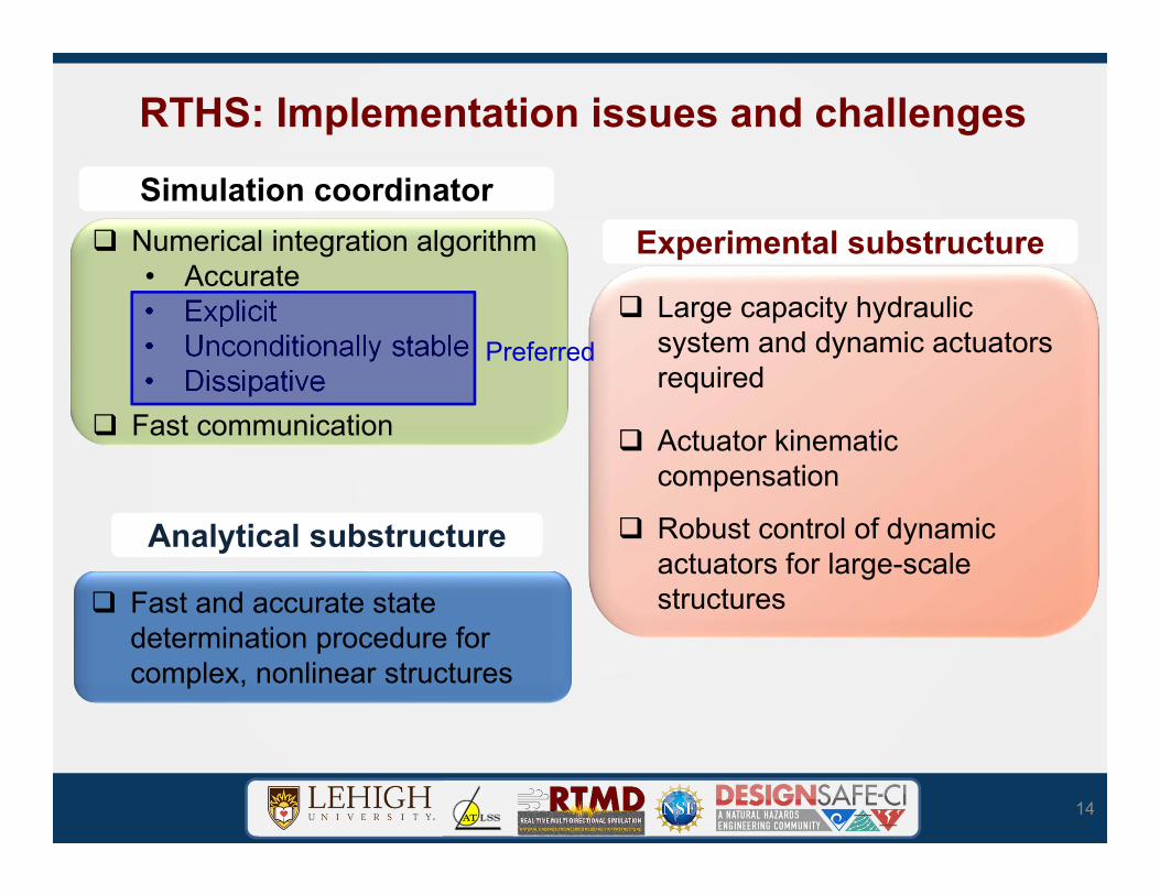
RTHS: Implementation issues and challenges
14
Analytical substructureAnalytical substructure
Fast and accurate state determination procedure for complex, nonlinear structures
Experimental substructureExperimental substructure
Large capacity hydraulic system and dynamic actuators required
Actuator kinematic compensation
Robust control of dynamic actuators for large-scale structures
Numerical integration algorithm• Accurate• Explicit• Unconditionally stable • Dissipative
Fast communication
Simulation coordinatorSimulation coordinator
Preferred
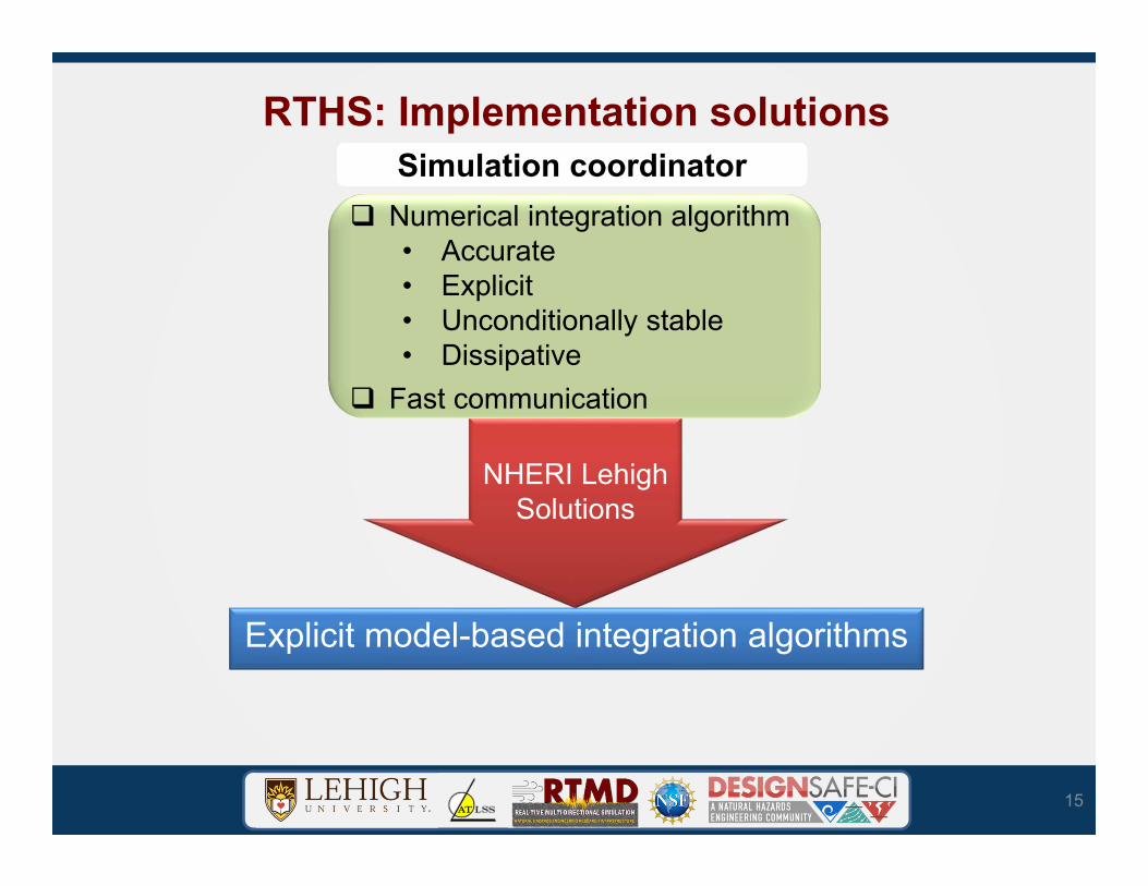
RTHS: Implementation solutions
15
NHERI Lehigh Solutions
Numerical integration algorithm• Accurate• Explicit• Unconditionally stable • Dissipative
Fast communication
Simulation coordinatorSimulation coordinator
Explicit model-based integration algorithms

16
Numerical Integration AlgorithmsExplicit Modified KR-𝛂 (MKR-𝛂) Method• Explicit Integration of Equations of Motion, Model-based• Unconditionally Stable• Controlled Numerical Damping – eliminate spurious high frequency
noiseVelocity update: 𝐗𝒏 𝐗𝒏 ∆𝑡𝛂𝟏𝐗Displacement update: 𝐗𝒏 𝐗𝒏 Δ𝑡𝐗𝒏 ∆𝑡 𝛂𝟐𝐗𝒏
Weighted equations of motion: 𝐌𝐗𝒏 𝐂𝐗𝒏 𝐊𝐗𝒏 𝐅𝒏
Kolay, C., and J.M. Ricles (2014). Development of a family of unconditionally stable explicit direct integration algorithms withcontrollable numerical energy dissipation. Earthquake Engineering and Structural Dynamics, 43(9), 1361–1380. http://doi.org/10.1002/eqe.2401
Kolay, C., and J.M. Ricles (2017) “Improved Explicit Integration Algorithms for Structural Dynamic Analysis with Unconditional Stability and Controller Numerical Dissipation,” Journal of Earthquake Engineering, http://dx.doi.org/10.1080/13632469.2017.1326423.
𝛂𝟏, 𝛂𝟐, and 𝛂𝟑: model-based integration parameters
*
*
Spurious higher modes (typ.)
*
*
Lower modes
of interest
(typ.)
Equi
vale
nt D
ampi
ng 𝜁
(%)
Stability: Root-Loci Controlled Numerical Damping
MKR- : One parameter ( ) family of algorithms• 𝜌 , Parameter controlling numerical energy dissipation
𝜌 spectral radius when Ω 𝜔Δ𝑡 → ∞ varies in the range 0 𝜌 1 𝜌 1: No numerical energy dissipation 𝜌 0: Asymptotic annihilation

Steel Structure with Nonlinear Viscous Dampers Studied using Large-scale RTHS
Plan view of prototype building Section view of prototype building
MRF
DBF
6 @25ft
6 @
25ft
6 @25ft
DBF DBF
MRF MRF
3 @
12.5
ft12
.5ft
3 @
12.5
ft
12.5
ft
North
East
NorthSouthSeismic tributary area NorthSouth
North
South
EastWest
Test structure
• Prototype building — 3-story, 6-bay by 6-bay office building located in Southern California— Moment resisting frame (MRF) with RBS beam-to-column
connections, damped brace frame (DBF), gravity load system, inherent damping of building
Dong, B., Sause, R., and J.M. Ricles, (2015) “Accurate Real-time Hybrid Earthquake Simulations on Large-scale MDOF Steel Structure with Nonlinear Viscous Dampers,” Earthquake Engineering and Structural Dynamics, 44(12) 2035–2055, https://DOI.org/10.1002/eqe.2572.
Dong, B., Sause, R., and J.M. Ricles, (2016) “Seismic Response and Performance of Steel MRF Building with Nonlinear Viscous Dampers under DBE and MCE,” Journal of Structural Engineering, 142(6) https://DOI.org/10.1061/(ASCE)ST.1943-541X.0001482.

Nonlinear Viscous Dampers
Damper testbed
Characterization testing
Damper force - deformation Damper force - velocity
0 2 4 6 8 10 12-1.5
-1
-0.5
0
0.5
1
1.5
Time (s)
Actu
ator
stro
ke (i
nche
s)
3 ramp downcycles
2 ramp upcycles 7 stable full cycles
Loading Protocol

Substructures for RTHS Phase-1
Large-scale RTHS on Structure with Nonlinear Viscous Dampers: Substructures
Analytical substructure (MRF, mass, gravity system,
inherent damping)
Experimental substructure (0.6-scale DBF)
Real-time state determination• Analytical substructure has 296 DOFs and 91 elements;• Nonlinear fiber elements for beams, columns, and RBS;• Nonlinear panel zone elements for panel zone of beam-column connection;• Elastic beam-column element for the lean-on column;• P-delta effects included in the analytical substructure.
RBS, typ.

MCE level RTHS using
20KR-𝛂 RTHSIntroduction ConclusionsKolay, C., Ricles, J., Marullo, T., Mahvashmohammadi, A., and Sause, R. (2015). Implementation and application of the unconditionally stable explicit parametrically dissipative KR-𝛼 method for real-time hybrid simulation. Earthquake Engineering & Structural Dynamics. 44, 735-755, doi:10.1002/eqe.2484.
Freq. 𝐟𝐍𝐪𝐲𝟏
𝟐𝚫𝒕
•Under nonlinear structural behavior, pulses are introduced in the acceleration at the Nyquist frequency when the state of the structure changes within the time step
•Pulses excite spurious higher modes present in the system which primarily contribute to the member forces
•Problem becomes worst by the noise introduced through the measured restoring forces and the actuator delay compensation which can amplify high frequency noise.

3-story Steel Frame Building with NL Viscous DampersMCE level RTHS using
21KR-𝛂 RTHSIntroduction ConclusionsKolay, C., Ricles, J., Marullo, T., Mahvashmohammadi, A., and Sause, R. (2015). Implementation and application of the unconditionally stable explicit parametrically dissipative KR-𝛼 method for real-time hybrid simulation. Earthquake Engineering & Structural Dynamics. 44, 735-755, doi:10.1002/eqe.2484.

RTHS: Implementation solutions
22
Explicit force-based fiber elements
NHERI Lehigh Solutions
Analytical substructureAnalytical substructure
• Fast and accurate state determination procedure

Fiber Element State Determination
23
FE Modeling of Analytical Substructure
Force-based fiber elements
Equilibrium is strictly enforced
Material nonlinearity can be modeled using a single element per structural member
Reduces number of DOFs
Requires iterations at the element level
Displacement-based fiber elements
Curvature varies linearly
Requires numerous elements per structural member to model nonlinear response
Increases number of DOFs
State determination is straight forward
3-D Fiber element
Jeopardizes explicit integration𝑄 𝑀 ,
𝐝 𝑑 𝑑 𝑑 Section deformation
𝐃 𝐷 𝐷 𝐷 Section forces
𝐪 𝑞 𝑞 𝑞 𝑞 𝑞 𝑞 Element deformations
𝐐 𝑄 𝑄 𝑄 𝑄 𝑄 𝑄 Element forces
𝑋
𝑌
𝑍
𝑄 𝑀 ,
𝑄𝑁
𝑠𝑇
𝑄 𝑀 ,
𝑄 𝑀 ,

Explicit-formulated Force-Based Fiber Element
24Kolay, C. and J.M. Ricles, (2018). Force-Based Frame Element Implementation for Real-Time Hybrid Simulation Using Explicit Direct Integration Algorithms. Journal of Structural Engineering, 144(2) http://dx.doi.org/10.1080/13632469.2017.1326423.
• Used with explicit integration algorithm• Material nonlinearity• Equilibrium is strictly enforced along element• Reduced DOFs in system modeling• Fixed number of iterations during state determination with carry-
over and correction of unbalanced section forces in next time step
𝑄 𝑀 ,
𝐝 𝑑 𝑑 𝑑 Section deformation𝐃 𝐷 𝐷 𝐷 Section forces𝐪 𝑞 𝑞 𝑞 𝑞 𝑞 𝑞 Element deformations𝐐 𝑄 𝑄 𝑄 𝑄 𝑄 𝑄 Element forces
𝑋
𝑌
𝑍
𝑄 𝑀 ,
𝑄 𝑁
𝑠 𝑇
𝑄 𝑀 ,
𝑄 𝑀 ,
3-D Fiber element – Deformation Modes

3-D EQ RTHS of RC Structure: Fiber Element Real-time State-Determination
25
Column develops inelastic behavior with cyclic strength and stiffness deterioration, and hysteretic pinching in force-
deformation response
Al-Subaihawi, S., Marullo, T., Cao, L., Kolay, C., and J.M. Ricles, (2019). 3-D Real-time Hybrid Earthquake Simulation of RC Buildings.
Column Cross-Section
108 fibers
y
z
Mom
ent
Mz
(kN
-m)
Mom
ent
My
(kN
-m)
Curvature z (1/m)
Curvature y (1/m)

RTHS: Implementation solutions
26
• Large hydraulic power supply system
• Large capacity dynamic actuators
• Servo hydraulic actuator control: Adaptive Time Series Compensator (ATS)
• Development of actuator kinematic compensation
NHERI Lehigh Solutions
Experimental substructureExperimental substructure• Large capacity hydraulic system and dynamic actuators required• Actuator kinematic compensation
• Robust control of dynamic actuators for large-scale structures

Servo Hydraulic Actuator Control
27
• Nonlinear servo-valve dynamics• Nonlinear actuator fluid dynamics• Test specimen material and
geometric nonlinearities• Slop, misalignment, deformations
in test setup
• Variable amplitude error and time delay in measured specimen displacement
• Inaccurate structural response• Delayed restoring force adds energy into
the system (negative damping)• Can cause instability
It is important to compensate

𝑢 𝑎 𝑥 𝑎 𝑥 𝑎 𝑥𝑢 𝑎 𝑥 𝑎 𝑥 𝑎 𝑥
Servo Hydraulic Actuator Control - Actuator Delay Compensation
𝑢 : compensated input displacement into actuator
𝑎 : adaptive coefficients
Adaptive coefficients are optimally updated to minimize the error between the specimen target and measured displacements using the least squaresmethod
A = a0k a1kank T Xm = xm xmdn
dtn xm
T
xm = xk1m xk2
m xkqm
T
Uc = uk1c uk2
c ukqm
T
(Output (measured) specimen displacement history)
(Input actuator displacement command history)
A = XmTXm -1
XmTUc
Adaptive Time Series (ATS) compensator
Chae, Y., Kazemibidokhti, K., and Ricles, J.M. (2013). “Adaptive time series compensator for delay compensation of servo-hydraulic actuator systems for real-time hybrid simulation”, Earthquake Engineering and Structural Dynamics, DOI: 10.1002/ eqe.2294.
𝑥 : target specimen displacement
NHERI Lehigh Solutions to RTHS Challenges
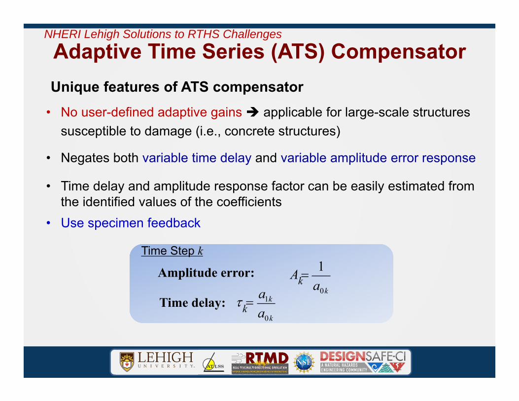
Unique features of ATS compensator• No user-defined adaptive gains applicable for large-scale structures
susceptible to damage (i.e., concrete structures)
Adaptive Time Series (ATS) Compensator
• Negates both variable time delay and variable amplitude error response
• Time delay and amplitude response factor can be easily estimated from the identified values of the coefficients
• Use specimen feedback
NHERI Lehigh Solutions to RTHS Challenges
Time delay:
Amplitude error: A 1a0k
a1k
a0k
k
k
Time Step k

MCE level RTHS using
30KR-𝛂 RTHSIntroduction ConclusionsKolay, C., Ricles, J., Marullo, T., Mahvashmohammadi, A., and Sause, R.. (2015). Implementation and application of the unconditionally stable explicit parametrically dissipative KR-𝛼 method for real-time hybrid simulation. Earthquake Engineering & Structural Dynamics. 44, 735-755, doi:10.1002/eqe.2484.
Actuator 3(Floor 3)
Actuator 2(Floor 2)
Actuator 1(Foor 1)

Actuator control: Typical MCE level RTHS &
31
𝐴 0.83 ~ 1.25
𝜏 18 ~ 75 msec
xt : targeted specimen displacement
xm : measured specimen displacement
NRMSE=0.13%NRMSE=0.14%NRMSE=0.29%
Amplitude Correction
Delay Compensation
Time History of Adaptive Coefficients
Floor-1 Floor-2 Floor-3a0
a1
a2
Synchronized Subspace Plots: xt vs. xm
Floor-1 Floor-2 Floor-3

Actuator Kinematic Compensation• Kinematic compensation scheme and implementation for RTHS (Mercan et al. 2009)
− Kinematic correction of command displacements for multi-directional actuator motions
− Robust, avoiding accumulation of error over multiple time steps; suited for RTHS
− Exact solution
Mercan, O, Ricles, J.M., Sause, R, and M. Marullo, (2009). “Kinematic Transformations in Multi-directional Pseudo-Dynamic Testing,” Earthquake Engineering and Structural Dynamics, Vol. 38(9), pp. 1093-1119.
))(
),(
SPNΘdΘMsinVM
ySNMSPNΘdΘMcosVMxSN(M)ySPN,x(SPN
m1,01
newm
1m
1,01newm
1newm
newm
))cos(ΘLMa),sin(ΘLMa()SNyLM,SNxL(M i2inewi2inewnewinewi -
inewinew
2iiinewinew
3 LMbLMa/cosyFLMbLMa
Θ2
)(arccos
22
3ii
inew2 Θ
/cosyFLMb
Θ sinarcsin
Multi-directional Real-time Hybrid Simulation
NHERI Lehigh Solutions to RTHS Challenges
Disp Transducers

NHERI Lehigh EF/ATLSS Testbeds
• Bracing Frame• Perform experiments on test
frame specimens of:Up to 13.7 m (45 ft) in heightUp to 11 m (36 ft) in width
Bracing Frame
5-story, 2-bay 2/3-scale MRF test specimen

NHERI Lehigh EF/ATLSS Testbeds
• Non-Structural Component Seismic Simulator • Enables multi-directional real-
time hybrid simulation of non-structural components and systems:Up to 12.2 m (40 ft) in lengthUp to 3.1 m (10 ft) in width
102 mm, 204 mm, or 406 mm pressurized pipeline hung/braced from truss
3.1 m x 12.2 m Rigid horiz. truss suspended from overhead frame
Actuator #1
Actuator #2
Actuator #3
Multi-directional Real-time hybrid simulation of building piping system
406 mm dia. Piping system filled with 1.38 MPa pressurized water

NHERI Lehigh EF/ATLSS Testbeds
• Full-scale Damper Testbeds• Enables full-scale damper tests:
Damper characterization testsReal-time hybrid simulations
• Stoke, velocity, and force capacity: +/- 500 mm (20 in.) stroke 1140 mm/s (45 in/s) for 1700 kN
actuators 840 mm/s (33 in/s) for 2300 kN
actuatorsActuator
#1
Actuator #4Dampers
Real-time hybrid simulation of building with four passive dampers

NHERI Lehigh EF/ATLSS Testbeds
• Tsunami Debris Impact Force Testbed• Enables full-scale debris impact tests:
High speed DAQ; high speed 5000 fps cameras
High bandwidth, resolution load cells Accelerometers, laser-displacement
transducers
Real-time simulation of impact forces from tsunami shipping container debris
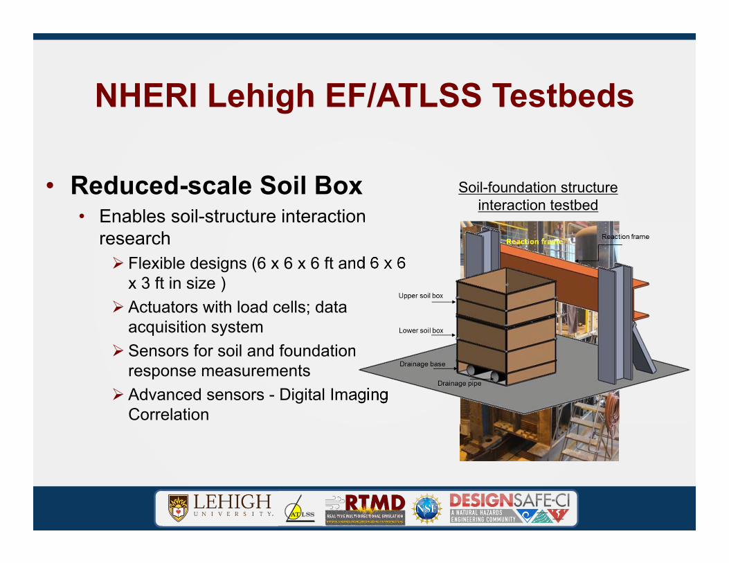
NHERI Lehigh EF/ATLSS Testbeds
• Reduced-scale Soil Box• Enables soil-structure interaction
research Flexible designs (6 x 6 x 6 ft and 6 x 6
x 3 ft in size ) Actuators with load cells; data
acquisition system Sensors for soil and foundation
response measurements Advanced sensors - Digital Imaging
Correlation
Soil-foundation structure interaction testbed
soil box
Reaction frame
Actuator

Guiding system
Pile Driver
Guidingsystem
Cone tip
Mandrel
Vibrator
Soil-Structure Interaction Testbed
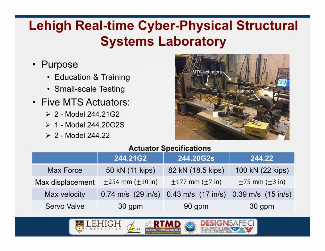
Lehigh Real-time Cyber-Physical Structural Systems Laboratory
• Purpose• Education & Training• Small-scale Testing
• Five MTS Actuators: 2 - Model 244.21G2 1 - Model 244.20G2S 2 - Model 244.22
244.21G2 244.20G2s 244.22Max Force 50 kN (11 kips) 82 kN (18.5 kips) 100 kN (22 kips)
Max displacement 254 mm ( 10 in) 177 mm ( 7 in) 75 mm ( 3 in)
Max velocity 0.74 m/s (29 in/s) 0.43 m/s (17 in/s) 0.39 m/s (15 in/s)Servo Valve 30 gpm 90 gpm 30 gpm
Actuator Specifications
MTS actuators
dampers

Existing ATLSS Infrastructure• 3-D Multi-directional reaction wall facility
• 3-dimensional• Up to 15.2 m (50 ft) height• 1.5 m (5 ft) anchor point grid
• Strong floor• 12.2 m by 30.5 m (40 ft by 100 ft)• Anchor assembly capacity
• 2,224 kN (500 kips) shear • 1,334 kN (300 kips) tension
• Hydraulic Supply System• Over 30 Hydraulic Actuators• Large array of Conventional Sensors• Crane• Skilled staff

NHERI Lehigh EF Hydraulic Equipment and Power
• Enables real-time EQ large scale demand to be imposed for up to 30 seconds
• Hydraulic supply system (ATLSS)– 5-120 gal/min variable axial piston pumps
• Accumulator System (NHERI)– 16 piston accumulators
• 50.2 gal each• 5 dynamic hydraulic actuators (NHERI)
– Maximum load capacity • 2 actuators: 517 kips at 3000 psi• 3 actuators: 382 kips at 3000 psi
– Stroke• +/- 19.7 in
– Maximum velocity• 45 in/s for 382 kip actuators• 33 in/s for 517 kip actuators
• 10 3-stage 550 gal/min Servovalves and HSMs (NHERI)

Other NHERI Lehigh EF Equipment
• High Speed 300+ Channel Data Acquisition System• 3 Real-Time Targets for simulation
coordination, including additional DAQ• Three real-time servo-hydraulic controllers• Sensors (displacement, accelerometers,
inclinometers)• Telepresence webcams• Specs for all equipment found in
NHERI Lehigh User’s Guidehttps://lehigh.designsafe-ci.org/resources
JR3

Instrumentation• Displacement transducers
• Strokes ranging from ±6.4mm (LVDTs) to 1524mm (linear potentiometers).
• Temposonic position sensors with a ±760 mm stroke, to a ±1100 mm stroke.
• All transducers are calibrated to within ±1% accuracy, with the LVDTs calibrated to within ±0.1%.
• Inclinometers ranging up to ±20 degrees with 1% accuracy.• Each hydraulic actuator is equipped with a load cell.
• All load cells are calibrated to within ±0.1% accuracy.

Other Major NHERI Lehigh EF Equipment• Real-time Integrated Control System
• Multiple Real-Time targets for simulation coordination with additional DAQ
• Three real-time servo-hydraulic controllers• High Speed 300+ Channel Data Acquisition System• Web and Data telepresence system• Local data repository
Real-TimeIntegrated Control System

NHERI Lehigh EF Control Room
Control Center• Houses Real-time Integrated
Control System• Camera Control• Data Acquisition System and
Server• Data Streaming System
VideoSensors
• Video Displays• Local Repository
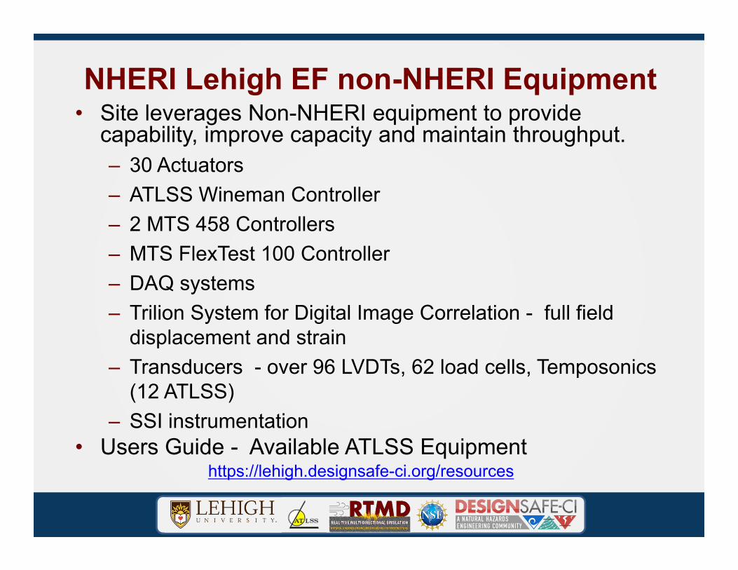
NHERI Lehigh EF non-NHERI Equipment• Site leverages Non-NHERI equipment to provide
capability, improve capacity and maintain throughput.– 30 Actuators – ATLSS Wineman Controller– 2 MTS 458 Controllers– MTS FlexTest 100 Controller– DAQ systems– Trilion System for Digital Image Correlation - full field
displacement and strain– Transducers - over 96 LVDTs, 62 load cells, Temposonics
(12 ATLSS)– SSI instrumentation
• Users Guide - Available ATLSS Equipmenthttps://lehigh.designsafe-ci.org/resources

Instrumentation• Digital imaging correlation (DIC) systems.
• Utilizes 3D image correlation method. • Works on both random and regular pattern, thus
simplifying sample preparation. • Same sensor uses white light to measure small and
large objects (1mm up to 100m) and strains in the range of 0.05% up to several 100%.
Figure F.4 DIC System
Digital Imaging Correlation System: reinforced concrete coupled-shear wall test specimen measured pier vertical displacements (courtesy M. McGinnis)
NEES@Lehigh Coupled Shear Wall Test Specimen with Multi-Directional Loading
(Source: Musial and Ram, 2010)
Lateral displacement (mm)
-40 -20 0 20 40 60 80
Dep
th a
long
the
pile
(mm
)
0
200
400
600
800
1000
1200
1400
1600
4468901338178022302676312235683799
Load (N)
Pile
Soil Surface
Rotation point shifts upward
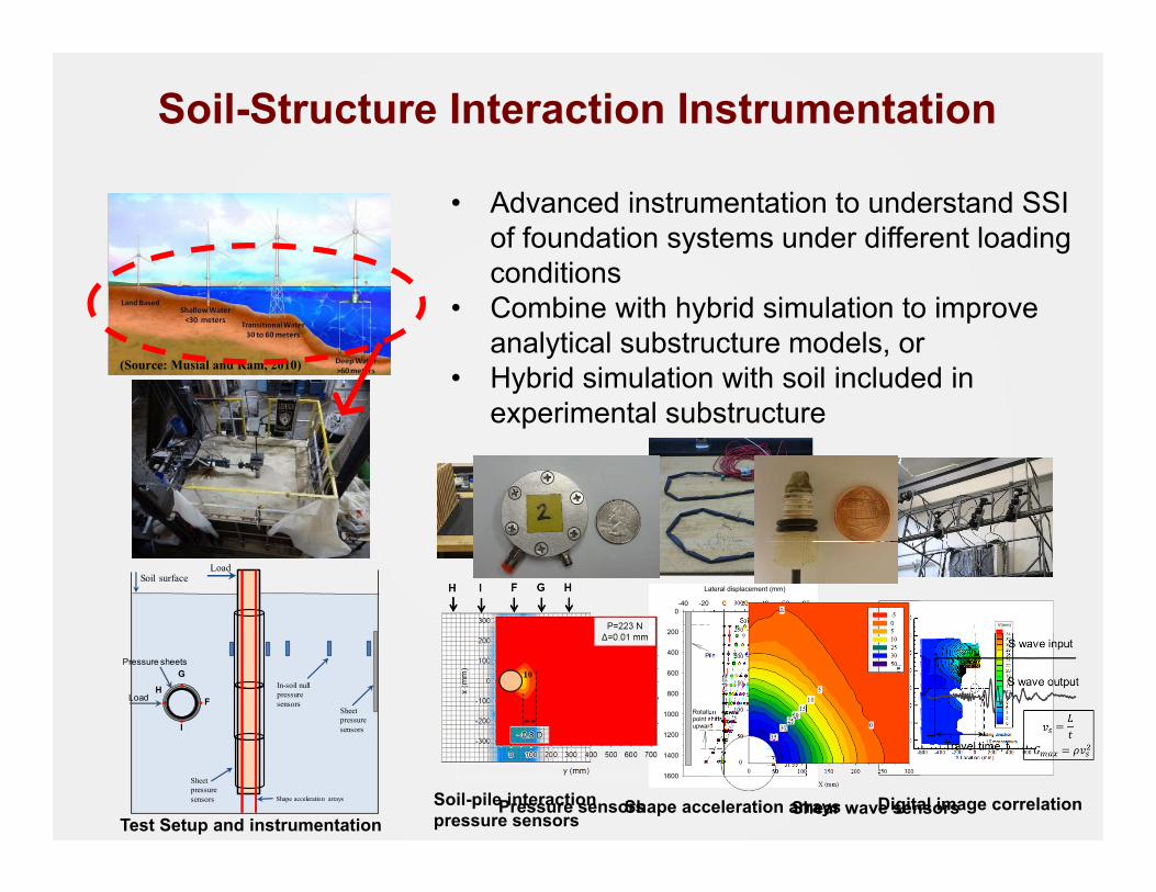
LoadSoil surface
Shape acceleration arrays
Sheet pressuresensors
In-soil null pressure sensors
Sheet pressuresensors
Test Setup and instrumentationSoil-pile interaction pressure sensors
Shape acceleration arrays Digital image correlation
X Location (mm)
YLo
catio
n(m
m)
-600 -400 -200 0 200 400 600
-600
-400
-200
0
200
400
600
800V(mm)
3432302826242220181614121086420
1.0 mm contoursloading direction
Soil-Structure Interaction Instrumentation
Pressure sheets
HF
G
I
Load
• Advanced instrumentation to understand SSI of foundation systems under different loading conditions
• Combine with hybrid simulation to improve analytical substructure models, or
• Hybrid simulation with soil included in experimental substructure
Pressure sensors Shear wave sensors

• Specimen Prep• Staging Areas• Machine Shop
• Laboratories• Intelligent Structures• Mechanical Testing• Welding and Joining• Materials• Microscopy
• Offices: Faculty; Staff; Visiting Researchers
• Meeting Rooms: Auditorium; Conference Room
• Storage Areas• Secure Facility
NHERI Lehigh EF - ATLSS Space and Resources
Specimen preparationstaging area
Auditorium – ECO Activities
Mechanicaltesting

• Real-time Integrated Control System• Configured with experimental protocol required by user to perform test
• Large-Scale Hybrid Simulation• Large-Scale Real-time Hybrid Simulation• Large-Scale Real-time Hybrid Simulation with Multiple Experimental
Substructures• Geographically Distributed Hybrid Simulation• Geographically Distributed Real-time Hybrid Simulation• Predefined load or displacements (Quasi-static testing or characterization
testing)• Dynamic testing• Semi-active controlled devices• On-line real-time model updating• Machine learning-based computational models
• Testing algorithms reside on an RTMDxPCand run in real time
• Experiments can be run in true real-time (real-timehybrid simulation, real-time distributed hybrid simulation, dynamic testing, characterization testing).
• Experiments can be run at an expanded time scale (hybrid simulation, distributed hybrid simulation, quasi-static testing).
• Distributed hybrid simulation via:• OpenFresco• Simcor• Custom software
• Flexible-designed system• Software and middleware packages developed by users or NHERI CI can be
plugged in and utilized for testing
NHERI Lehigh EF Experimental Protocols
https://lehigh.designsafe-ci.org/protocols/experimental-protocol/

• Real-time Integrated Control System• Hydraulics-off mode
• Used for validation of testing methods/algorithms,training, education
• Both servo-hydraulic control system, test structure and numerical substructure modeled analytically
NHERI Lehigh EF Experimental Protocols
Eqns. of Motion(Num. Integ)
ucxtarg
Actuator Delay Compensation
RI=f(𝑥,𝑥)
Restoring Forces
Excitation
𝐺0.009086z2 0.02565z + 0.0023z3 − 2.243z2 + 1.568z − 0.3195

• Real-time Integrated Control System• Hydraulics-off mode
• Used for validation of testing methods/algorithms,training, education
• Both servo-hydraulic system, test structure and any analytical substructure modeled analytically
• Safety• Software limits are enabled on the
System.• Hardware actuator positon stroke and
test specimen displacement limit switches placed.• Emergency stop system activated throughout
laboratory
NHERI Lehigh EF Experimental Protocols
Auditorium – ECO Activities

• Real-time Integrated Control System• Hybrid simulation:
• Robust integration algorithms: Explicit MKR- Integration Algorithm -Explicit unconditionally stable integration algorithm with controlled numerical energy dissipation and controlled overshoot (Kolay and Ricles, 2014, 2017)
• Adaptive actuator control: Adaptive Time Series (ATS) Compensator(Chae et al. 2013)
• Multi-directional actuator control: Multi-directional Kinematic Compensation (Mercan et al. 2009)
NHERI Lehigh EF Experimental Protocols
Kolay, C., & Ricles, J. (2014). “Development of a family of unconditionally stable explicit direct integration algorithms with controllable numerical energy dissipation.” Earthquake Engineering & Structural Dynamics, 43(9), 1361–1380. DOI:10.1002/eqe.2401
Kolay, C., and J.M. Ricles (2017). “Improved Explicit Integration Algorithms for Structural Dynamic Analysis with Unconditional Stability and Controllable Numerical Dissipation,” Journal of Earthquake Engineering, http://dx.doi.org/10.1080/13632469.2017.1326423
Chae, Y., Kazemibidokhti, K., and Ricles, J.M. (2013). “Adaptive time series compensator for delay compensation of servo-hydraulic actuator systems for real-time hybrid simulation.” Earthquake Engineering and Structural Dynamics, 42(11), 1697–1715, DOI: 10.1002/ eqe.2294.
Mercan, O, Ricles, J.M., Sause, R, and M. Marullo, (2009). “Kinematic Transformations in Multi-directional Pseudo-Dynamic Testing,” Earthquake Engineering and Structural Dynamics, Vol. 38(9), pp. 1093-1119.
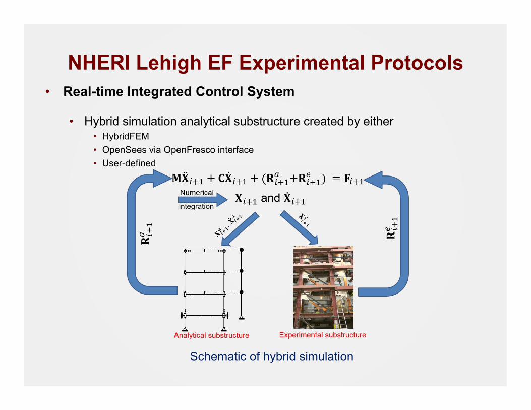
• Real-time Integrated Control System
• Hybrid simulation analytical substructure created by either• HybridFEM• OpenSees via OpenFresco interface• User-defined
NHERI Lehigh EF Experimental Protocols
Schematic of hybrid simulation

HybridFEM• MATLAB and Simulink based computational modeling
and simulation coordinator software for dynamic time history analysis of inelastic-framed structures and performing real-time hybrid simulation
• Simulink architecture facilitates real-time testing through multi-rate processing
• Run Modes• MATLAB script for numerical simulation• Simulink modeling for Real-Time Hybrid simulation with
experimental elements via Real-Time Targets, and hydraulics-off for training and validation of user algorithms.
• User’s Manual for training

NHERI Lehigh HybridFEMConfiguration Options:• Coordinate system of nodes• Boundary, constraint and restraint conditions• Explicit-formulated Elements
• Elastic beam-column• Elastic spring• Inelastic beam-column stress resultant element• Non-linear spring• NL Displacement-based beam-column fiber elem• NL Force-based beam column fiber element• Zero-length• NL planar panel zone• Elastic beam-column element with geometric stiffness• User-defined Reduced Order Modeling elements
• Geometric nonlinearities• Steel wide flange sections (link to AISC shapes Database)• Reinforced concrete sections• Structural mass & inherent damping properties• Adaptable integration methods• Real-time online model updating• Machine learning-based computational modeling• Semi-active control laws
• Materials• Elastic• Bilinear elasto-plastic• Hysteretic• Bouc-Wen• Trilinear• Stiffness degrading• Concrete• Steel• Fracture• Initial stress• Prestress/Posttensioning
JR5JR6

Telepresence
• Data Turbine (RBNB) (dataturbine.org)• Aggregates data from SCRAMNet
using RTMD tools to define channellist, sample rate and duration
• Streaming of data and images locally and remotely• Additional storage archive of test data

Real-Time Data Viewer
• Real-Time Data Viewer (RDV)• Connect from anywhere on any system• Invaluable tool for visualizing
Real-Time Hybrid Simulations

3D Model Panel for RDV
• 3D Modeling for RDV• Real-time visualization of
complete structural system in hybrid simulation

Video
• Video/Imaging systems• (24) Amcrest Bullet/PTZ IP Cameras (up to 8k)• (4) Sony SNC-EP550 HD (720p HD)• (9) GoPro Hero 3 Black camcorders (1080p60 HD)• (2) Sony SNC-RZ30N network cameras (SD Security)• Nikon D70 D-SLR camera• HD camcorders available
upon request through Lehigh
• Blue Iris Servers• Portal for all users to access and
control web cameras• Archived video available for
previous experiments

IT InfrastructureData

RTMDdata
• Synology DS 1817• 8 hard drive slots, 96 TB capacity up to 216 TB• 10Gb Connection
• Dual-disk Redundancy • Network Attached Storage• Public and Private storage

Data Management Plan• Local repository for data storage managed by NHERI Lehigh with
offsite backup risk mitigation through DesignSafe-CI• Unlimited Google Drive space through Lehigh University • Locally stored data adheres to the Lehigh University records
retention policy or extended by the ATLSS Center IT management• Included under NHERI Lehigh data management umbrella:
• Unprocessed and RAW data from experiments• Converted and derived data sets using computational software• Experimental photos and videos• Computational models and analytical data sets• Scripts and software developed for project tasks
• Local curation utilizing folder/file structure• Project/Date/Task Description/Data Set; format “testname_date”
• Automated Globus Project data upload • DesignSafe-CI curation through Data Depot and Data Model

Training: Hands on
• Familiarize users with testing methodologies and IT equipment
• Introduce users to softwareand user tools
• Describe all safety requirements• Perform validation studies on
physical test bed• Demonstrate various
simulation techniques

Training: Documentation
• User’s Guide• Repository of
technical documents, demos and video tutorials
• Available to all users

Users Guide
• Details of the Equipment Specifications, Experimental Protocols, and Equipment Inventory are given in the User’s Guide
https://lehigh.designsafe-ci.org/resources/

Thank you