ngps - user's manual - caenels - manufacture of … – user’s manual 2 caen els s.r.l. via...
TRANSCRIPT

NGPS – User’s Manual
1
NGPS
High-Stability and High-Precision New Generation
Power Supply Series
User’s Manual
All Rights Reserved © CAEN ELS s.r.l. & Energy Technology s.r.l.
Rev. 1.02 – September 2017
MA
GN
ET P
OW
ER
S
UP
PL
Y S
YS
TE
MS

NGPS – User’s Manual
2
CAEN ELS s.r.l. via Vetraia, 11
55049 Viareggio (LU) – Italy Mail: [email protected] Web: www.caenels.com
OC Energy Technology s.r.l.
via della Solidarieta', 2/1 40056 Valsamoggia (BO) – Italy
Mail: [email protected]
Web: www.ocem.eu

NGPS – User’s Manual
3
User Manual – Models – Options – Custom Models
This manual covers the following standard Power Supplies models:
• NGPS 120-50E
• NGPS 120-50A
• NGPS 140-50E
• NGPS 200-50E
• NGPS 200-50A
This manual covers the Custom Model named as following:
NGPS-Cxx yyy-zzzK
Where:
• xx is the Customization code
• yyy is the maximum output current expressed in Amps
• zzz is the maximum output voltage expressed in Volts
• K is the Input Mains Ratings

NGPS – User’s Manual
4
Table Of Contents
1. INTRODUCTION .............................................................................................. 11
1.1 NGPS OVERVIEW ......................................................................................... 11 1.2 NGPS AT A GLANCE ...................................................................................... 13 1.3 MODES OF OPERATION .................................................................................. 15
Regulation Mode ...................................................................................... 15
Control Mode ........................................................................................... 15 Update Mode ............................................................................................ 16
1.4 INTERLOCK AND STATUS SIGNALS ................................................................ 17 Interlock Enable/Disable Mask ................................................................ 19 Interlock Activation Level Mask .............................................................. 19
Interlock Intervention Time ...................................................................... 19 Interlock Identification Name .................................................................. 20
Output Status ............................................................................................ 20 1.5 REMOTE SENSING ......................................................................................... 21 1.6 TRIGGER AND ANALOG CONTROL INPUTS ..................................................... 24
Trigger input ............................................................................................ 24
Analog Control input ............................................................................... 25 1.7 FRONT PANEL INDICATORS ........................................................................... 26
1.8 INTERNAL PROTECTIONS ............................................................................... 26 Earth Leakage Current ............................................................................ 27 Earth Fuse ................................................................................................ 27
Regulation Fault ...................................................................................... 27 OVerPower - OVP ................................................................................... 28
OVerTemperature - OVT ......................................................................... 28
AC Mains Fail .......................................................................................... 29
1.9 WAVEFORM .................................................................................................. 29 1.10 STATUS REGISTER ......................................................................................... 30
2. INSTALLATION ............................................................................................... 31
2.1 PREPARATION FOR USE .................................................................................. 31
2.2 INITIAL INSPECTION ...................................................................................... 31 2.3 MOUNTING .................................................................................................... 31 2.4 AC INPUT POWER CONNECTION ................................................................... 32
AC Source requirement ............................................................................ 35 2.5 LOAD CONNECTION ....................................................................................... 35
Wire selection ........................................................................................... 35 2.6 GROUNDING OUTPUTS .................................................................................. 37
3. LOCAL CONTROL .......................................................................................... 38
3.1 NAVIGATION SWITCH.................................................................................... 38 3.2 DISPLAY ........................................................................................................ 38
Power-up .................................................................................................. 39 Home Screen ............................................................................................ 40
Menu Page ............................................................................................... 42 Control Page ..................................................................................... 43 Config Page ...................................................................................... 44

NGPS – User’s Manual
5
Advanced Page ................................................................................. 45
4. SOFTWARE COMMANDS ............................................................................. 46
4.1 ETHERNET INTERFACE .................................................................................. 46 4.2 COMMAND SYNTAX ...................................................................................... 46
4.3 COMMAND REPLIES ...................................................................................... 47 4.4 ERROR TABLE ............................................................................................... 49 4.5 COMMAND TABLE ......................................................................................... 50 4.6 BASIC COMMANDS ........................................................................................ 53
MON Command ....................................................................................... 53
MOFF Command ..................................................................................... 54 VER Command ......................................................................................... 55 MST Command ......................................................................................... 56 MRESET Command ................................................................................. 57 MRI Command ......................................................................................... 58
MRV Command ........................................................................................ 59 LOOP Command ...................................................................................... 60
MWI Command ........................................................................................ 62 MWV Command ................................................................................... 63 MWIR Command .................................................................................. 64 MSRI Command ................................................................................... 66
MWVR Command ................................................................................. 67 MSRV Command .................................................................................. 69
MRT Command .................................................................................... 70 MRW Command ................................................................................... 71 MGC Command ................................................................................... 72
MRID Command .................................................................................. 73 4.7 CONFIGURATION COMMANDS ....................................................................... 74
MRG Command ....................................................................................... 76
MWG Command ....................................................................................... 77
PASSWORD Command ............................................................................ 78 MSAVE Command ................................................................................... 80 UPMODE Command ............................................................................... 80 SETFLOAT Command ............................................................................. 81
5. NGPS UTILITIES ............................................................................................. 82
5.1 DEVICE MANAGER ........................................................................................ 82 Searching for connected devices .............................................................. 83 Device Configuration ............................................................................... 84
5.2 VISUAL PS .................................................................................................... 85
Power Supply IP ...................................................................................... 85 Main windows .......................................................................................... 86 Unit Configuration ................................................................................... 87
Firmware Update ..................................................................................... 88
6. MECHANICAL DIMENSIONS ....................................................................... 90
7. TECHNICAL SPECIFICATIONS .................................................................. 91
NGPS – User’s Manual
6
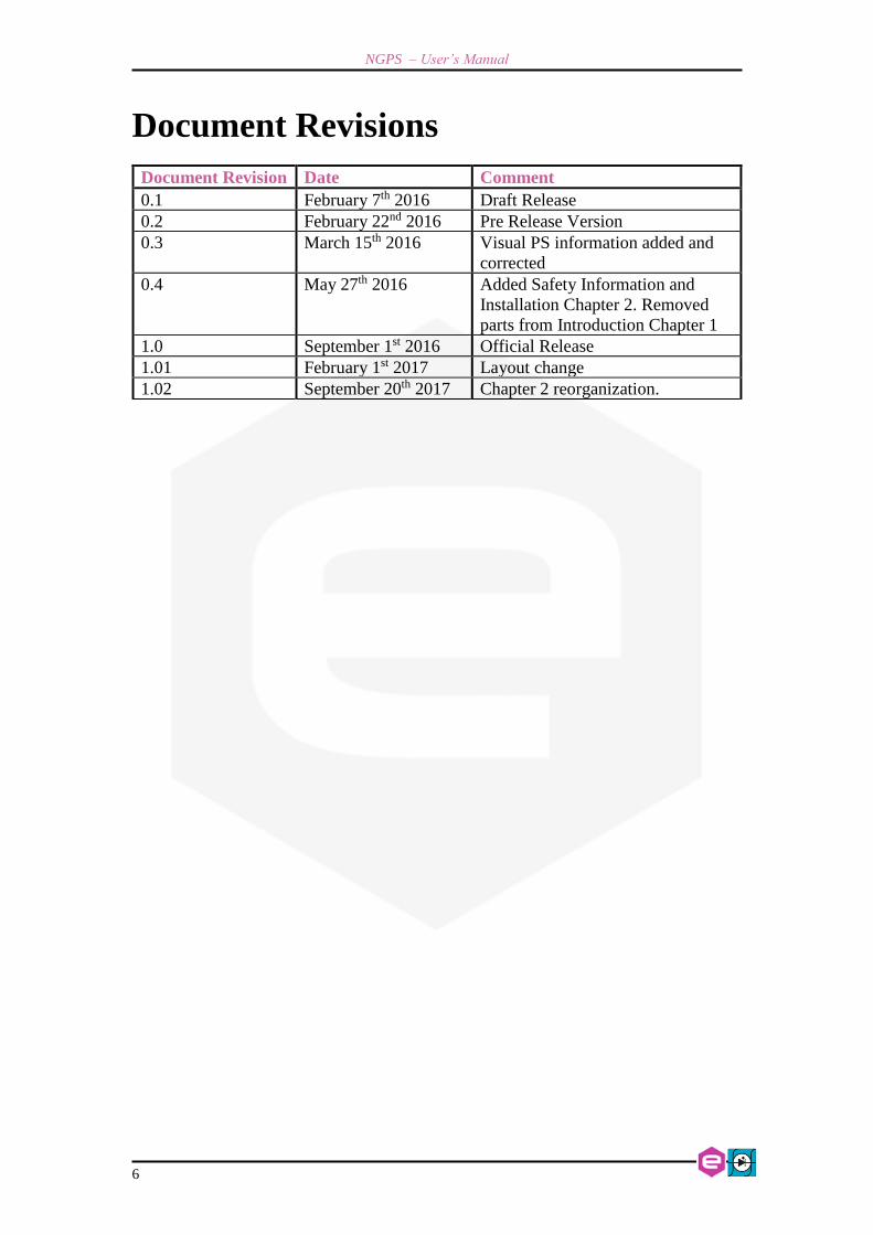
Document Revisions
Document Revision Date Comment
0.1 February 7th 2016 Draft Release
0.2 February 22nd 2016 Pre Release Version
0.3 March 15th 2016 Visual PS information added and
corrected
0.4 May 27th 2016 Added Safety Information and
Installation Chapter 2. Removed
parts from Introduction Chapter 1
1.0 September 1st 2016 Official Release
1.01 February 1st 2017 Layout change
1.02 September 20th 2017 Chapter 2 reorganization.

NGPS – User’s Manual
7
Safety information
The following table shows the general environmental requirements for a correct
operation of instruments referred in this User’s Manual:
Environmental Conditions Requirements
Environment Indore use
Operating Temperature 0°C to 40°C
Operating Humidity 20% to 80% RH (non-condensing)
Altitude Up to 2000 m
Pollution degree 2
Overvoltage Category II
Storage Temperature -10°C to 60°C
Storage Humidity 5% to 90% RH (non-condensing)
The following symbols are used within this manual or are reported in the box and
along this manual:
• CAUTION Risk of Electrical Shock
• Caution: Documentation must be consulted in all cases where
this symbol is marked
• Indicates ground terminal
• Protective Ground Conductor Terminal
• 0 Off (Power)
• I On (Power)

NGPS – User’s Manual
8
• The WARNING sign denotes a hazard. An attention
to a procedure is called. Not following the procedure correctly could result in
personal injury. A WARNING sign should not be skipped and all indicated
conditions must be fully understood and met.
• The CAUTION sign denotes a hazard. An attention to
a procedure is called. Not following procedure correctly could result in
damage to the equipment. Do not proceed beyond a CAUTION sign until all
indicated conditions are fully understood and met.
CAEN ELS s.r.l. and Energy Technology s.r.l. will repair or replace any product
within the guarantee period if the Guarantor declares that the product is defective due
to workmanship or materials and has not been caused by mishandling, negligence on
behalf of the User, accident or any abnormal conditions or operations.
Please read carefully the manual before operating any part of the instrument
Do NOT open the BOX TOP
COVER
CAEN ELS s.r.l. and Energy Technology s.r.l. declines all responsibility for
damages or injuries caused by an improper use of the Modules due to negligence
on behalf of the User. It is strongly recommended to read thoroughly this User's
Manual before any kind of operation.
CAEN ELS s.r.l. and Energy Technology s.r.l. reserve the right to change partially or
entirely the contents of this Manual at any time and without giving any notice.
WARNING
CAUTION
WARNING

NGPS – User’s Manual
9
Disposal of the Product
The product must never be dumped in the Municipal Waste. Please check your local
regulations for disposal of electronics products.

NGPS – User’s Manual
10
• Do not use this product in any manner not specified by
the manufacturer. The protective features of this product
may be impaired if it is used in a manner not specified in
this manual.
• Do not use the device if it is damaged. Before you use the
device, inspect the instrument for possible cracks or
breaks before each use.
• Do not operate the device around explosives gas, vapor
or dust.
• Always use the device with the cables provided.
• Turn off the device before establishing any connection.
• Do not operate the device with the cover removed or
loosened.
• Do not install substitute parts or perform any
unauthorized modification to the product.
• Return the product to the manufacturer for service and
repair to ensure that safety features are maintained
WARNING

NGPS – User’s Manual Installation
11
1. Introduction
This chapter describes the general characteristics and main features of the NGPS –
New Generation Power Supply series.
1.1 NGPS Overview
High performances, high efficiency, high stability, easiness of configuration and
maintenance are the key features of the NGPS power supply series, generated by the
joint effort of CAEN ELS and OCEM – Power Electronics.
The NGPS is an independent current- or voltage-controlled digital monopolar
power supply module. There are available different models with different current and
voltage ranges:
Model Name Current Voltage Maximum Power
NGPS 120-50 120 A 50 V 6 kW
NGPS 140-50 140 A 50 V 7 kW
NGPS 150-60 150 A 60 V 9 kW
NGPS 200-50 200 A 50 V 10 kW
Table 1: NGPS models
The NGPS units (Table 1) are available in two different versions for the three-
phase input voltage:
Version Three-Phase Input
“A” 208 V (AC)
“E” 400 V (AC)
Table 2: NGPS versions
The NGPS module is composed of a single 19-inch 3U standard crate. The
power unit implements a completely digital control loop with a Pulse Width Modulation
(PWM) generation technique that allows adapting the system to any load condition.

Installation NGPS – User’s Manual
12
The control board houses a dedicated FPGA with integrated dual-core ARM
CPU. The loop regulation task is performed directly by the FPGA logic, in order to
have high performance and deterministic loop control. On the ARM CPU it is installed
an embedded Linux OS, that supervises all process as communication, diagnostics and
local interface handling.
Remote communication is guaranteed by means of an Ethernet 10/100/1000
autosensing socket present on the front panel of the power unit. The power supply can
be also monitored and controlled via a navigation switch and a graphic high resolution
color display featuring user-friendly menus.
In addition to the standard Ethernet interface it is possible to communicate with
the unit using the SFP-ports on the front panel. This interface allows to communicate
with the unit using a proprietary packet structure with a very high update rate (more
than 10 kHz). These ports are connected directly to the FPGA logic and so the given
packet is elaborated directly by the hardware logic.
This approach eliminates the software stratification that manages the packet and
the computational time is smaller and deterministic, allowing a very high update rate of
the setpoint, giving the user more flexibility and excellent rates for the digital control
of the power supply.

NGPS – User’s Manual Installation
13
1.2 NGPS at a glance
The NGPS system is composed by a single 19-inch 3U crate. The NGPS unit and
its I/O connections can be easily seen in Figure 1 (front view) and Figure 2 (rear view).
Figure 1: NGPS front view
On the front side of the NGPS unit are placed: a circuit breaker, a colour graphic
display with navigation switch for the local control of the module, three communication
sockets (2 SFPs and one Ethernet ports), four status LEDs and one USB device
connector.
Figure 2: NGPS rear view
On the rear side of the unit are placed: three-phase input connector, earth
connection terminal, output terminals, the D-Sub 15 Female Pin I/O connector and a
connector for the voltage remote sensing.

Installation NGPS – User’s Manual
14
Some models can mount one or two BNC connectors reserved for additional
features of the power supply.

NGPS – User’s Manual Installation
15
1.3 Modes of Operation
The NGPS system has multiple features and multiple configurations that allow
using the unit for a very widespread topology of applications.
A brief summary of the basic configurations that the unit is able to handle are
hereafter presented.
Regulation Mode
The NGPS can be used as current-controlled or voltage-controlled bipolar units.
The regulation types are:
• C.C. mode: it is the Constant Current regulation mode. The power supply
regulates the output current set by the user;
• C.V. mode: it is the Constant Voltage regulation mode. The power supply
regulates the output voltage set by the user.
In C.V. mode it is possible to use the remote sensing terminals that allow
regulating the output voltage directly on the load thus compensating the voltage drops
on the output cables. The maximum voltage drop that the power supply is able to
compensate is of 1V.
Control Mode
The NGPS unit can be controlled in three main different ways, hereafter listed:
• LOCAL control: the unit can be controlled directly via the front panel color
display and the navigation switch. When the unit is set in LOCAL mode it is
possible to perform readings and monitor from the remote interface but any
setting command is denied;
• REMOTE control: the unit is controlled via the TCP-IP Ethernet interface.
The setting and control of the unit can be performed exclusively via this
interface while monitoring is still possible from the local display;
• FAST-INTERFACE control: this interface allows controlling the unit via a
proprietary protocol over the SFP/SFP+ interfaces (optical or electrical) and
it is meant to be used for very fast applications. Update rates of more than 10
kHz are reachable using this communication channel.
Installation NGPS – User’s Manual
16
Update Mode
The current or voltage setting of the unit can also be performed in four different
modes:
• NORMAL: the update of the set-point (current or voltage, depending on the
operation mode) is performed as soon as a new set-point is received via the
remote, local or fast interfaces;
• WAVEFORM: the update of the set-point is performed on a specific timing
(defined as a “waveform” attribute, more information on the Waveform
section) and it is done internally;
• TRIGGER: the set-point is updated by an external event – i.e. a hardware
trigger coming from the rear BNC connector. Please note that this mode of
operation is obtainable only on the units that have the external trigger input
connector installed (ordering option – factory configurable);
• ANALOG INPUT: the unit is controlled by an external signal that is fed to
the rear BNC connector. The unit acts as a C.C. or C.V. generator depending
on the pre-set Regulation Mode. This option is only available in units that
have been factory configured (ordering option).
Please note that the last two Update Modes of operation are available only in
models that have been factory configured at the time of purchase to have the Trigger
Input and/or the Analog Control Input features.

NGPS – User’s Manual Installation
17
1.4 Interlock and status Signals
The NGPS module has four configurable dry-contact input interlocks and two
output status signals that are directly available on the D-Sub 15 Pin Female connector
on the rear panel (Figure 3).
A mating connector, a standard D-Sub 15 Pin Male type, can be installed in
order to use/access these available signals.
Figure 3: I/O Connector
The pin index of the D-Sub 15 rear connector is summarized in the following
table:
Pin Number Signal name
#1 Interlock #1 return
#2 Interlock #2 return
#3 Interlock #3 return
#4 Interlock #4 return
#5 DO NOT CONNECT
#6 DO NOT CONNECT
#7 Solid State Relay- Terminal #2
#8 Solid State Relay- Terminal #1
#9 Interlock #1 input
#10 Interlock #2 input
#11 Interlock #3 input
#12 Interlock #4 input
#13 Magnetic Relay Common Contact (C-TAP)
#14 Magnetic Relay Normally Closed Contact (NC-TAP)
#15 Magnetic Relay Normally Open Contact (NO-TAP)
Table 3: D-sub 15 Pin pin-out
Pin #1 Pin #8
Pin #9 Pin #15

Installation NGPS – User’s Manual
18
Magnetic Relay Contact (C-TAP, NO-TAP & NC-TAP) and
Solid State Relay Terminals (Terminal #1 & #2) shall not float
more than ±60VDC above/below chassis ground.
Interlocks input and return pins shall not float more than
±60VDC above/below chassis ground.
Voltage between relay C-TAP and NC-TAP or NO-TAP pins
shall never exceed ± 48 V.
Maximum current rating for the Magnetic Relay is 1 A;
current trough pins #13 and #14 or pins #13 and #15 shall
never exceed 1 A.
Maximum current rating for the Solid State Relay is 400 mA;
current trough pins #7 and #8 shall never exceed 1 A.
Do not apply voltage between any input interlock and its
corresponding return.
The interlock pins are galvanically isolated from ground and outputs terminal,
nevertheless the absolute maximum voltage, referred to ground, that pins can sustain is
48V. The two interlocks inputs have their own return connection. The interlock is
hardware-activated when the input pin and its corresponding return pin are shorted.
The system is provided with four external interlock inputs that can be easily
configured using the VISUAL PS graphic software (provided with the power unit) or
directly using the standard power supply commands. A detailed description of the
configuration of the external interlock using the power supply commands is hereafter
described.
Two output status signals provide the output status of the power module: when
the module is ON, the Normally Closed contact (NC-TAP) switch opens and vice-versa.
The Solid-state relay close the terminals when the module is ON.
WARNING
CAUTION

NGPS – User’s Manual Introduction
19
Interlock Enable/Disable Mask
The NGPS series external interlock can be enabled or disabled by writing to the
corresponding Interlock Enable/Disable Mask field of the advanced configuration
parameters (field #90), using the MWG command. The value to be written is in ASCII
format, representing the corresponding bit mask, as shown in the following table:
Bit #4
(INT #4)
Bit #3
(INT #3)
Bit #2
(INT #2)
Bit #1
(INT #1)
Enabled (1)
Disabled (0)
Enabled (1)
Disabled (0)
Enabled (1)
Disabled (0)
Enabled (1)
Disabled (0)
Table 4: Enable/Disable Mask Parameter
Example: if only interlock #2 and interlock #3 need to be enabled, it is
necessary to write 0x6 (it is ASCII representation to the bit mask 0110) to the field #90.
The following command has to be se sent to the power supply (after having un-locked
the password protection): “MWG:90:0x6\r”.
Interlock Activation Level Mask
Each external interlock can be chosen to trip at high or low logic level. The high
level means that the interlock trips when the interlock input signal is shorted, otherwise
the low level that the interlock trips when the input is open. To configure the interlock
state mask it is necessary to write on the advanced configuration parameters (field #91).
The value to be written is an ASCII format representing the corresponding bit mask, as
shown in the following table:
Bit #4
(INT #4)
Bit #3
(INT #3)
Bit #2
(INT #2)
Bit #1
(INT #1)
High (1)
Low (0)
High (1)
Low (0)
High (1)
Low (0)
High (1)
Low (0)
Table 5: Activation Level Mask Parameter
Example: if interlock #1 and interlock #4 need to have a high activation level
(trip when the interlock input signal is shorted), it is necessary to write 0x9 (it is ASCII
representation to the bit mask 1001) to the field #91. The following command has to be
se sent to the power unit: “MWG:91:0x9\r”. This setting has no effect if the interlock
is not enabled.
Interlock Intervention Time
The module allows to set also the interlock intervention time (how long an
interlock signal needs to be at its activation level before tripping and thus generating a
Introduction NGPS – User’s Manual
20
fault condition). The Intervention time parameters are stored in the field #92 for
Interlock #1, in field #94 for interlock #2, in field #96 for interlock #3 and in field #98
for interlock #4. The value to be set is in ASCII format, representing the intervention
time in milliseconds. The minimum settable value is 0 (immediate generating of fault
condition) and the maximum value is 10.000 ms (corresponding to 10 seconds).
Example: if interlock #1 needs to have an interlock intervention time of 750 ms,
the following command has to be se sent to the power unit: “MWG:92:750\r”. This
setting has no effect if the interlock is disabled.
Interlock Identification Name
The NGPS also allows associating a name to the interlocks in order to read form
the remote interface or to display on the local display the interlock condition name. The
Intervention names are stored in the field #93 for Interlock #1, in field #95 for interlock
#2, field #97 for interlock #3 in field #99 for interlock #4. The value to be set is in
ASCII format, representing the interlock name.
Example: if the interlock #1 is associated to the cabinet door open, the following
command can to be se sent to the power unit: “MWG:93:Cabinet door\r”. This setting
has not effect if the interlock is disabled.
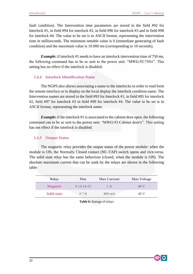
Output Status
The magnetic relay provides the output status of the power module: when the
module is ON, the Normally Closed contact (NC-TAP) switch opens and vice-versa.
The solid state relay has the same behaviour (closed, when the module is ON). The
absolute maximum current that can be sunk by the relays are shown in the following
table:
Relay Pins Max Current Max Voltage
Magnetic # 13-14-15 1 A 48 V
Solid state # 7-8 400 mA 48 V
Table 6: Ratings of relays

NGPS – User’s Manual Introduction
21
1.5 Remote Sensing
There is a potential shock hazard at the sense point when
using power supply with rated output voltage greater than 60
V. Ensure that the connections at the load end are shielded to
prevent accidental contact with hazardous voltages.
A short from VSENS+ or VOUT+ to VSENS– or VOUT– will
cause damage to the power supply. Reverse the sense wire
might cause damage to the power supply in local and remote
sensing. Do not connect +S to – or –S to +.
The NGPS mounts a voltage-sensing connector on the rear panel that allows
using the voltage sensing feature especially when using the power supply in C.V. mode.
Connector is shown in Figure 4.
Figure 4: Remote Sensing Connector
The NGPS is provided as factory-default with a mating connector already
shorting the pins 1-2 and 3-4 in order to have direct sensing at the output terminals.
Figure 5: Factory mating connector
WARNING
CAUTION
Pin #1 Pin #4

Introduction NGPS – User’s Manual
22
The two remote sensing terminals are present on the corresponding connector
on the rear panel:
Description Pin Name
VSENSE + #1 +S
VOUT + #2 +
VOUT – #3 –
VSENSE – #4 –S
Table 7: Remote sensing pinout
By using these two “sensing” pins it is possible to sense the output voltage
directly on the load, thus recovering possible voltage drops on the output cables up to
1V.
It is strongly suggested to use twisted cables when using the remote sensing
feature in order to minimize possible noise pick-up.
The NGPS is shipped with a mating connector for the remote sensing that short-
circuits the +S and + pins and the –S and – pins respectively. This configuration
performs the remote sensing directly at the output connector of the power unit. Leaving
+S and –S pins disconnected will make the power supply sense the output voltage
directly at the output terminal connections. When using the remote sensing feature leave
pins #2 (+) and #3 (–) disconnected.
Follow the instructions below to configure the power supply for remote
sensing:
1. Ensure that Mains switch is on Off position “O”
2. Remove factory jumpers between +S to + and –S to –.
3. Using a twisted pair or shielded cable (suggested wire size is 0.3 or 0.5
mm2) connect the +S terminal to the positive output terminal and the –S
to the negative output terminal as illustrated in Errore. L'origine
riferimento non è stata trovata..
4. For NGPS with output voltage rating > 60 V Fix the Safety cover to the
rear panel using the four M3x8 mm screw.

NGPS – User’s Manual Introduction
23
In order to perform remote sensing at different points – e.g. the load terminals
– it would be necessary to connect Pin #1 and Pin #4 as in Figure 6:
Figure 6: Example of Remote Sensing
NGPS
LO
AD
+S
-S
+
-
Power Cables
Sensing Cables
OUTPUT
CONNECTOR

Introduction NGPS – User’s Manual
24
1.6 Trigger and Analog Control inputs
On the rear side of the NGPS there are two BNC input connectors, as shown in
Figure 7, which can be used as trigger and analog control inputs.
Figure 7: Trigger and Analog input connectors
Trigger input
The trigger input accepts TTL (5V) and LVTTL (3.3V) compatible signals and
should be driven by a low-impedance source or generator.
The logic levels are subject to a hysteresis that allows for this recognized values
that guarantee correct operation of the trigger as listed in Table 8:
Logic Level Value
Low-to-HIGH > 2.2 V
High-to-LOW < 0.7 V
Table 8: Trigger Logic Levels
The absolute maximum rating for the Trigger Input signal is
of 5.5 V (a higher voltage level applied to this input can
seriously damage the device).
A visual representation of the voltage levels for the trigger operation is
presented in the following Figure 8:
CAUTION

NGPS – User’s Manual Introduction
25
Figure 8: Trigger Thresholds
Analog Control input
The analog control input allows controlling the NGPS unit as an “amplifier”.
This input is labelled as “AN CTRL”.
This input accepts signals ranging from 0V to +10V and generates an output
which is proportional to the input signal, zero output for a 0V input and Full-Scale
output for a +10V input. An example of the relation between the analog input signal
and the output (can be either current or voltage, depending on the Regulation mode) is
shown in Figure 9.
Figure 9: AN CTRL vs OUTPUT dependence
0
1
2
3
4
5
6
Trigger Input
HIGH LEVEL
LOW LEVEL
Analog Control
Analog Input Output
0%
+10V
0V
100%
ABSOLUTE MAXIMUM
Trigger Signal
50%
+5V

Introduction NGPS – User’s Manual
26
1.7 Front Panel Indicators
The NGPS has four (4) front panel LED indicators as shown in the following
Figure 10.
Figure 10: front panel indicators
The front panel indicators and their behaviour are hereafter listed (clockwise
starting from top-left):
• C.C.: Constant Current mode (blue). If turned on, the NGPS is working in
constant-current mode. When off, it is regulating the ouput voltage;
• STAT (green): signals the correct operation of the module diagnostics. The
blinking signaling the correct operation has a 1-second period;
• OUT ON (blue): it signals if the output is enabled or not. The blue LED is on
if the output is enabled and it is regualting output current or voltage;
• ALARM (red): if turned on signals that the power unit has experienced a fault
condition. It is necessary to perform a “reset fault” command in order to turn off
this LED and to turn to module output again (only if the fault condition/cause
has been removed).
1.8 Internal Protections
The NGPS is equipped with several internal protections that allow configuring
the unit for optimal operation. These protections have the dual use of protecting the unit
and the connected load/device from unwanted damages or undesired operation
conditions.
A brief description of the NGPS internal protections is hereafter presented with
some more basic considerations on their operation and use.

NGPS – User’s Manual Introduction
27
Earth Leakage Current
This protection continuously monitors the current flowing to earth and it has a
settable threshold [A] that can be set by experienced users. The tripping of this
protection generates a fault condition that shuts the power supply output off.
Earth Fuse
An earth fuse is present on the rear side of each NGPS and it is rated at
F5AH500VAC. The blowing of this fuse generates a fault condition of the power unit
and the fuse needs to be replaced in order to get rid of the fault condition before resetting
the NGPS internal status register. The fuse housing is shown in Figure 11.
Figure 11: earth fuse housing
Regulation Fault
This fault is generated when the power supply is not able to correctly regulate
the output current or output voltage (in CC and CV mode respectively).
Different thresholds for the differential current, differential voltage and the
intervention time can be set by experienced users.
A typical example of a regulation fault is represented by a 1Ω load on a NGPS
200-50 for example where the maximum power supply output voltage is 50V. By
setting a current of 100A to the load, the output voltage should reach a value of 100V
which obviously is not feasible: once the power unit supplies 50A to the load it already
reaches the maximum output voltage condition. The power unit recognizes this
difference between the set-point – i.e. 100A – and the actual output current, thus
generating a “regulation fault” condition.

Introduction NGPS – User’s Manual
28
The tripping of this fault implies an automatic turning off of the NGPS unit. A
status reset – i.e. reset faults – needs to be performed in order to turn the unit back on.
OVerPower - OVP
The NGPS can work continuously at a 1% over its power rating as expressed in
the specifications.
The module is able to work at a power comprised between 1% and 5% over its
rating – i.e. between 101% and 105% – for a 20-second period before turning off on an
over-power fault.
If the actual output power drawn from the power supply is more than 5% above
its nominal ratings the power unit will shut down after 1 second.
This behaviour is summarized in the following Table 9 (an example of a NGPS
200-50 unit is also listed):
Output Power Time of Operation
< 101% of PN
e.g. NGPS 200-50: < 10.1 kW Continuous
> 101% and < 105% of PN
e.g. NGPS 200-50: > 10.1 kW and < 10.5 kW 20 s
≥ 105% of PN
e.g. NGPS 200-50: ≥ 10.5 kW 1 s
Table 9: NGPS Output Power
where PN is the rated nominal output power of the power supply unit, as
indicated in the technical specifications.
OVerTemperature - OVT
Internal monitoring of temperature is performed in different places inside the
NGPS power supply. If a pre-defined threshold is exceeded by any of these internal
sensors, an OVT condition is generated, thus shutting off the power unit.
The threshold value [°C] can be set by experienced users. A reset fault operation
needs to be executed on the status register of the NGPS before turning the output off
again.

NGPS – User’s Manual Introduction
29
AC Mains Fail
A continuous monitoring of the AC Mains is performed in order to always
guarantee the capability of obtaining the maximum voltage from the power supply. If
there is some problem on the mains, the power supply unit could not be able to regulate
correctly and a mains fail conditions is generated.
It is necessary to reset the status register and to eliminate cause of fault before
turning the power supply back on again.
1.9 Waveform
The NGPS is able to act as a waveform generator both in current and in voltage
regulation modes.
The waveform is stored internally in a point-by-point manner and it gives a lot
of flexibility since the maximum number of points of the waveform can be defined as
well as the sampling period (of the waveform execution).
The minimum time interval for the waveform execution period is rated at 0.1
ms = 100 µs, giving an equivalent output waveform update rate of 10 kHz.
In order to correctly execute the output waveform it is necessary to “tune” the
PID regulator parameters of the power supply to the specific load (and have an adequate
load at the output).
More information on the waveform feature can be found in the corresponding
command section.

Introduction NGPS – User’s Manual
30
1.10 Status Register
The following table shows the NGPS internal status register structure:
Bit # Bit name Description
#31 OVP Over Power condition
#30 DCCT FAULT DCCT Not working properly
#29 Ext. Interlock #4 External interlock 4 has tripped
#28 Ext. Interlock #3 External interlock 3 has tripped
#27 Ext. Interlock #2 External interlock 2 has tripped
#26 Ext. Interlock #1 External interlock 1 has tripped
#25 / reserved
#24 Regulation Fault Modules has experienced a regulation fault
#23 Earth Fuse Earth fuse is blown
#22 Earth Leakage Earth current leakage fault
#21 Mains Fault Mains fail condition
#20 OVT Over Temperature condition
#19 / reserved
#18 / reserved
#17 / Input Over Current
#16 / Output Over Voltage
#15 / reserved
#14 / reserved
#13 Waveform Waveform is in execution
#12 Ramping Module is ramping current or voltage
#11 / reserved
#10 / reserved
#9 / reserved
#8 / reserved
#7 - #6 Update mode [2 bits] Normal [00], Waveform [01], Triggered FIFO [10], Analog input [11]
#5 Regulation mode C.C. [0] or C.V. [1] output regulation mode
#4 / reserved
#3 - #2 Control Mode [2 bits] Indicates the mode of operation of the unit (Remote [00], Local [01])
#1 Fault condition This bit is set if the module has experienced a fault condition
#0 ON/OFF This bit is set when the module is enabled and correctly regulating the output
Table 10: Status Register structure

NGPS – User’s Manual Local Control
31
2. Installation
This chapter contains instructions for initial inspection, preparation for use
2.1 Preparation for use
In order to be operational the power supply must be connected to an appropriate
AC source. The AC source voltage should be within the power supply specification. Do
not apply power before reading this chapter. Table 11 below, describes the basic setup
procedure. Follow the instructions in the sequence given to prepare the power supply
for use.
Step Checklist Description
1 Initial inspection Physical inspection of power supply
2 Mounting Installing the power supply, ensuring proper ventilation
3 AC Input Power Connection Connect the power supply to the AC source
5 Load connection Wire size selection, Remote Sensing
4 First switch-on Switch-on checkout procedure
Table 11: Installation checklist
2.2 Initial inspection
Prior to shipment this power supply was inspected and found free of mechanical
or electrical defects. Upon unpacking of the power supply, inspect for any damage
which may have occurred in transit.
The inspection should confirm that there is no exterior damage to the power
supply such as broken switch or connectors and that the all panel and display are not
scratched or cracked. Keep all packing material until the inspection has been completed.
If damage is detected, compile the RMA form available to the CAEN ELS web site.
2.3 Mounting
The NGPS is a rack-mount device since the unit form factor is designed to be
installed in a standard 19-inch cabinet.

Introduction NGPS – User’s Manual
32
This power supply is fan cooled, the air intake is at the front
panel and the exhaust is at the rear panel. Upon installation
allow cooling air to reach the front panel ventilation inlets.
Allow minimum 10 cm of unrestricted air space at the front
and the read of the unit.
The NGPS power supply series is designed to fit in a standard 19” equipment
rack.
Use a support bar to provide adequate support for the power
supply.
2.4 AC Input Power Connection
Connection of this power supply to an AC power source
should be made by an electrician or other qualified
personnel. Do not exceed the torque specified on input stud
terminals.
There is a potential shock hazard if the power supply chassis
(with cover in place) is not connected to an electrical safety
ground via the safety ground in the AC input stud terminals.
CAUTION
CAUTION
CAUTION
WARNING
NO

NGPS – User’s Manual Local Control
33
The three-phase input connector on the rear panel is a Phoenix Contact 1777749
(PC 5/4-ST1) connector. The three-phase ground has to be connected on the bottom
terminal, as shown in Figure 12. The phases can be connected to any of the three upper
phase terminals (the connection order of the phases is not defined).
Tightening torque shall be between 0.5 to 0.8 Nm.
Perform all these operation with the cables and the power
supply disconnected from the AC mains.
Figure 12: Three-phase input connector
Recommended Cable Size for Input Connection are listed in
Input voltage Current RMS per phase Recommended copper
wire size
208 V 34 A 6 mm2
400 V 18 A 4 mm2
Table 12: AC Cable size
The AC input current and voltage rating is marked on the rear terminal of the
power supply.
The Protective Earth Ground must be connected before
applying AC Line Power to the power supply. There is a
potential shock hazard if the power supply chassis is not
connected to an electrical safety ground via the safety ground
in the AC input connector!
WARNING
WARNING

Introduction NGPS – User’s Manual
34
After connecting the input connector to the crate mating connection, it is
necessary to mount the metal protective cover by first screwing the four M4 threaded
screw (top and bottom of the cover Figure 13) and then by rotating the cable fastener.
Figure 13: Protective cover mounting
Figure 14: AC Mains cable fastener
For safety reasons, the mains supply voltage ratings should not exceed the
indicated voltage range.

NGPS – User’s Manual Local Control
35
AC Source requirement
The NGPS power supplies are designed for 208 V AC input range or for 400 V
AC input range depending on the model; frequency ranging from 47 Hz to 63 Hz.
Installation Category shall be CAT II so maximum impulse voltage on the network
mains must be below 2500 V.
2.5 Load connection
Turn off the AC input power before making or changing any
rear panel connection. Ensure that all connections are
securely tightened before applying power. There is a
potential shock hazard when using a power supply with a
rated output greater than 60 V
Wire selection
Two factors must be considered for the selection of the wires:
• Current carrying capacity -> Cross section area
• Maximum wire length.
• Insulation voltage
Wire cross section and length
Wire size should be selected to enable voltage drop per lead to be less than 1 V
at the maximum power supply current to prevent excessive output power consumption.
Suggested wire sizes are listed in the following table:
Wire Cross
Section Area
[mm2]
Resistivity [Ω/km]
Maximum Cable length in meters to limit
voltage drop to be less than 2 V (1 V per lead)
120 A 200 A
35 0.524 16 -
50 0.387 21 -
70 0.268 31 18,5
95 0.193 43 25,5
120 0.153 54 32,5
Table 13: Wire selection
Voltage ratings of the cable shall be rated for the maximum output voltage of the NGPS
power supply.
WARNING

Introduction NGPS – User’s Manual
36
If values of Table 13 are used the maximum voltage to the load will be limited
to:
NGPS nominal output voltage + Maximum compensation Voltage if
Remote sensing is used – Cable Drop Voltage
Maximum compensation Voltage for all models is 1 V
Lug Terminal connection
Cable lug terminal shall be for M8 screws.
Screws provided with the NGPS should be used for screw the
cable lug. Maximum length of the screws is 20 mm. Longer
screws may damage the power supply.
Tightening torque shall be between 4 to 5 Nm.
Always use spring washer and plane washer for a reliable
connection.
The load needs to be connected to the output terminals placed on the rear panel
of the unit as shown in Figure 15. This type of terminals offers a convenient and reliable
form of connection. These screw connections accept standard M8 connections and the
terminals are already threaded.
Figure 15: Output terminal connections (insert screw and secure it)
The symbols “+” and “-” on the rear panel indicate the positive and negative
polarity of the terminal respectively.
After securing both output connections it is necessary to mount the metallic
protective cover since the power supply has the capability of delivering a high current
CAUTION

NGPS – User’s Manual Local Control
37
on these outputs and/or hazardous voltage for NGPS with output voltage ratings > 60
V.
Figure 16: Output terminal connections (insert screw and secure it)
2.6 Grounding Outputs
By factory default configuration the NGPS minus terminal is grounded to the
Protective Ground (i.e. chassis, Mains-Earth terminal and all metallic parts composing
the box) through a fuse. This fuse called Earth Fuse (E.F.) is accessible form the back
panel. With this configuration the Output Terminals are not floating and cannot be
connected to Protective Ground.
If accidentally one of the output terminals is conducting to the Protective
Ground a fault will be triggered switching the power supply Off. Refer to Earth Fuse
Fault and Earth Leakage Fault.
To allow floating operation of the output it is sufficient to remove the Earth Fuse
from the fuse-holder and set the Power supply for Floating operation (refer to section
4.7.1).
When the FAST-PS is configured to operate in floating mode either the positive or
negative output terminals can be grounded. Always use two wires to connect the load
to the power supply regardless of how the system is grounded.
Models up to 60VDC Rated Output shall not float outputs
more than ±60VDC above/below chassis ground. Models >
60VDC Rated Output shall not float outputs more than
±500VDC above/below chassis ground.
WARNING

Introduction NGPS – User’s Manual
38
3. Local Control
This chapter describes the local control functionalities that are provided by the
NGPS power supply and some useful information on how to use it.
The power supply can work either in LOCAL mode or in REMOTE mode. Please
note that only readbacks are allowed from the remote communication interfaces when
the unit is in LOCAL mode (i.e. settings are inhibited).
The control mode (LOCAL / REMOTE) can be set on the configuration page of
the local menu.
3.1 Navigation Switch
Each NGPS power supply module is equipped with a Navigation Switch on the
front panel of the unit as shown in the following Figure 17:
Figure 17: Navigation switch
There are multiple actions that can be performed via this front navigation switch:
• Left, Right, Up, Down arrow pushbuttons;
• Internal encoder rotation (CW and CCW);
• Central pushbutton (it will also be referred to as “Enter”).
3.2 Display
The colour display on the NGPS power supply unit allows users to visualize
information about the power supply status and to control the unit in order to use it
locally. Screens and pages of the display can be navigated from the navigation switch
though user friendly menus and sub-menus.

NGPS – User’s Manual Local Control
39
Power-up
The NGPS, upon power-up or power-cycling, will display an empty screen until
the unit embedded OS is initialized.
Please note that this procedure will take approximately 25-seconds before
the Home Screen is displayed.

Local Control NGPS – User’s Manual
40
Home Screen
The NGPS home screen is the first loaded page upon power-up or power-cycling
of the module, it is shown in Figure 18, and contains information on:
• the NGPS model;
• the module IP address;
• output current readback value [A] with the light blue status bar;
• output voltage readback value [V] with the green status bar;
• the status of the output – i.e. ON or OFF;
• the status of the control – i.e. Local or Remote;
• the module Identification Name;
• the regulation mode of the unit – i.e. constant-current or constant-voltage.
Figure 18: Home Screen
The Home screen presents some indications on the right side as:
• ON – OFF: shows if the power supply output is enabled or not;
• REM – LOC – FCI: shows if the module is in Local, Remote or Fast Control
Interface control mode;
• C.C. – C.V.: shows if the module is working in C.C. or in C.V. regulation mode.
An example of the indications on the right side of the Home screen is hereafter
shown in Figure 19:
Figure 19: Home Screen indicators

NGPS – User’s Manual Local Control
41
If the module has experienced one or more faults – e.g. interlock intervention,
over-temperature, etc. – the home page screen would display a list the faults, turning
also the module OFF.
The power supply latches on every fault recognized by the internal logic so that
every type of fault is recorded: this means that the first fault happening does not ban
the other ones to be recorded so that, giving users more information, permits a better
investigation of the fault cause.
Local Control NGPS – User’s Manual
42
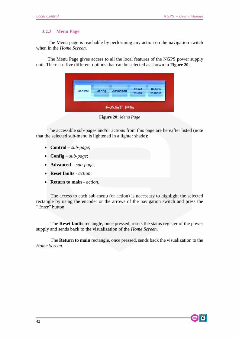
Menu Page
The Menu page is reachable by performing any action on the navigation switch
when in the Home Screen.
The Menu Page gives access to all the local features of the NGPS power supply
unit. There are five different options that can be selected as shown in Figure 20:
Figure 20: Menu Page
The accessible sub-pages and/or actions from this page are hereafter listed (note
that the selected sub-menu is lightened in a lighter shade):
• Control – sub-page;
• Config – sub-page;
• Advanced – sub-page;
• Reset faults - action;
• Return to main - action.
The access to each sub-menu (or action) is necessary to highlight the selected
rectangle by using the encoder or the arrows of the navigation switch and press the
“Enter” button.
The Reset faults rectangle, once pressed, resets the status register of the power
supply and sends back to the visualization of the Home Screen.
The Return to main rectangle, once pressed, sends back the visualization to the
Home Screen.

NGPS – User’s Manual Local Control
43
Control Page
The Control Page is reachable by selecting the corresponding rectangle from the
Menu Page.
The Control Page gives access to the main settings of the NGPS power supply
unit. An example of a Control Page visualization is shown in Figure 21:
Figure 21: Control Page
From this screen it is possible to turn the power supply unit ON and OFF and to
set the output current or voltage (depending on the regulation type, C.C. or C.V.).
Actual values of output current and output voltage (readbacks) can also be seen
at the bottom line of this page.
Local Control NGPS – User’s Manual
44
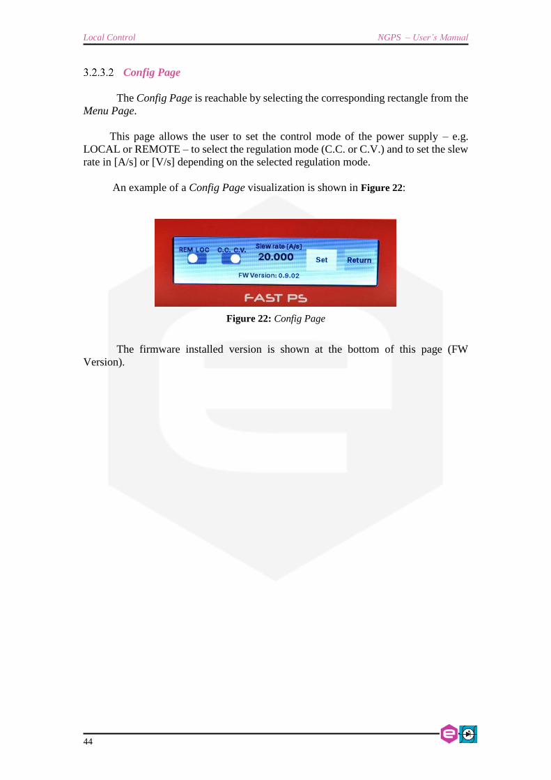
Config Page
The Config Page is reachable by selecting the corresponding rectangle from the
Menu Page.
This page allows the user to set the control mode of the power supply – e.g.
LOCAL or REMOTE – to select the regulation mode (C.C. or C.V.) and to set the slew
rate in [A/s] or [V/s] depending on the selected regulation mode.
An example of a Config Page visualization is shown in Figure 22:
Figure 22: Config Page
The firmware installed version is shown at the bottom of this page (FW
Version).

NGPS – User’s Manual Local Control
45
Advanced Page
The Advanced Page is reachable by selecting the corresponding rectangle from
the Menu Page.
This page allows to locally set the power supply Ethernet IP address, the Network
Mas and the Gateway.
An example of an Advanced Page visualization is shown in Figure 23:
Figure 23: Advanced Page
It is very important to notice that once the "OK" button has been clicked,
the user can remotely communicate and get control of the power supply again only
by opening a new TCP socket to the IP that has just been set.

Software Commands NGPS – User’s Manual
46
4. Software Commands
This chapter describes the base TCP/IP software commands used for the control
and configuration of the NGPS power module.
4.1 Ethernet Interface
The device is shipped with default IP address, subnet mask, and gateway and
TCP-IP communication port:
Parameter Factory Value
IP address 192.168.0.10
Subnet mask 255.255.255.0
Gateway 192.168.0.1
TCP/IP port 10001
Table 14: Default Ethernet Settings
4.2 Command Syntax
The command syntax used by the NGPS protocol is described in the following
sections.
Commands must be sent in ASCII format and are composed by a “command
field” and one, two or none “parameter field”, separated by a colon (“:” or “0x3A” in
hexadecimal notation). The number of “parameter fields” depends on the specific
command. Commands are NOT case sensitive and therefore the command string can
be sent either using uppercase or lowercase characters (conversion to uppercase
characters is performed internally). Each command must be terminated with the
termination sequence. The NGPS supports two termination sequences:
• “carriage return” termination char “\r” (“0x0D” in hexadecimal notation
or commonly CR) or
• “carriage return\line feed” sequence “\r\n” (“0x0D 0x0A” in hexadecimal
notation or commonly CRLF).

NGPS – User’s Manual Software Commands
47
Command Example:
MWI:20.5580\r or MWI:20.5580\r\n
• “MWI” is the command field;
• “:” is the parameter’s separation character;
• “20.5580” is the first parameter field;
• “\r” or “\r\n” are the termination sequences of the command.
In the following command description the “\r” termination char is used, but it
can be always replaced with the termination sequence “\r\n”.
Commands are processed one at a time; therefore user must wait for a
response from the unit before sending the next command.
All the responses from the NGPS module are in upper case and are terminated
with the same “carriage return\line feed” sequence (“\r\n”), “0x0D 0x0A” in
hexadecimal notation or commonly CRLF.
MWI:10.5875\r\n
#ACK\r\n
or:
MWI:10.5875\r
#ACK\r\n
4.3 Command Replies
The reply from the module depends on the given command. In general the
command can be grouped in two categories: Write commands and Read commands.
For write commands there are two specific replies that indicate that the
command has been correctly elaborated or not. Those replies are hereafter presented:
AcKnowledge (“#AK”) indicates that the command is valid and it was correctly
elaborated by the device:
#AK\r\n
• “#AK” is the AcKnowledged response to a valid command;
• “\r\n” is the termination sequence of the reply.

Software Commands NGPS – User’s Manual
48
Not AcKnowledge (“#NAK”) indicates that the command is either not valid or that
it was not accepted by the device; the “NAK” reply is followed by an “error code”
field, which can be used to determine the cause of the error (see the List of the
Error Codes appendix for a detailed list of all possible error codes):
#NAK:01\r\n
• “#NAK” is the Not AcKnowledged response to an invalid command;
• “:” is the parameter’s separation character;
• “01” is the error code,
• “\r\n” is the termination sequence of the reply.
For read commands, the replies are generally formed by an echo string,
followed by the corresponding read value. The echo string is preceded by the hash
character (“#”) and the echo is separated from the “:” separation character.
Some examples are hereafter shown:
MRI\r
#MRI:12.8875\r\n
or:
MWI:?\r
#MWI:10.9850\r\n
or:
MRG:90\r
#MRG:90:0x2\r\n
• the read commands are highlighted in blue;
• the echo string is highlighted in green;
• the read value is in purple;
• the termination char is highlighted in red.
For more detailed information about the single command please refer to the specific
command section.

NGPS – User’s Manual Software Commands
49
4.4 Error Table
The list of error codes returned with the #NAK reply and their description are
hereafter shown:
Error Code # Description
01 Unknown command
02 Unknown Parameter
03 Index out of range
04 Not Enough Arguments
05 Privilege Level Requirement not met
06 Saving Error on device
07 Invalid password
08 Power supply in fault
09 Power supply already ON
10 Setpoint is out of model limits
11 Setpoint is out of software limits
12 Setpoint is not a number
13 Module is OFF
14 Slew Rate out of limits
15 Device is set in local mode
16 Module is not in waveform mode
17 Module is in waveform mode
18 Device is set in remote mode
19 Module is already in the selected loop mode
20 Module is not in the selected loop mode
99 Unknown error
Table 15: NAK Error code table

Software Commands NGPS – User’s Manual
50
4.5 Command Table
The list of commands used by the NGPS and the corresponding syntax is
hereafter presented as well as a description of each command purpose and any special
requirements related to the specific command. The base commands are summarized in
the following table:

NGPS – User’s Manual Software Commands
51
Command Read/
Write Parameter #1 Parameter #2 Detailed description Reply value
VER R / / Return the module model and installed firmware
versions
ASCII indicating the module model and firmware
version
MON W / / Turn on the module “AK” or “NAK”
MOFF W / / Turn the module OFF “AK”
LOOP W
R
“I” or “V”
“?”
/
/
Set the power module loop mode
Query for the power supply loop mode
“AK” or “NAK”
Loop mode (“I” or “V”)
MRI R / / Read output current value ASCII indicating the output read current
MRV R / / Read output voltage value ASCII indicating the output read voltage
MWI W
R
I Setpoint
“?”
/
/
Set the new current setpoint (ASCII)
Query for the last applied current setpoint
“AK” or “NAK”
ASCII indicating the current setpoint
MWV W
R
V Setpoint
“?”
/
/
Set the new voltage setpoint (ASCII)
Query for the last applied setpoint
“AK” or “NAK”
ASCII indicating the voltage setpoint
MWIR W
R
I Setpoint
“?”
/
/
Go to the given setpoint with a ramp (ASCII)
Query for the last accepted final ramp setpoint
“AK” or “NAK”
ASCII indicating the current setpoint
MWVR W
R
V Setpoint
“?”
/
/
Go to the given setpoint with a ramp (ASCII)
Query for the last accepted final ramp setpoint
“AK” or “NAK”
ASCII indicating the voltage setpoint
MSRI W
R
I Ramp Slew rate
“?”
/
/
Set the I ramp slew rate [A/s] (ASCII)
Query for the I ramp slew-rate
“AK” or “NAK”
ASCII indicating the I ramp slew-rate
MSRV W
R
I Ramp Slew rate
“?”
/
/
Set the I ramp slew rate [V/s] (ASCII)
Query for the I ramp slew-rate
“AK” or “NAK”
ASCII indicating the I ramp slew-rate
MRT R / / Read Heatsink Temperature [°C] ASCII indicating the temperature value

Software Commands NGPS – User’s Manual
52
Command Read/
Write Parameter #1 Parameter #2 Detailed description Reply value
MRW R / / Read estimated active output power value [W] ASCII indicating the active output power value
MGC R / / Read leakage current value [A] ASCII indicating the Leakage voltage value
MRID R / / Read module identification Module identification (ASCII)
MST R / / Read module internal status register Internal status register (Hex representation)
MRESET W / / Reset the module status register “AK” or “NAK”
PASSWORD W
R
Password word
“?” /
Set the password word (ASCII)
Query for the actual user privileges
“AK” or “NAK”
User privileges (ASCII representation)
MRG R Parameter field # Read the given parameter field Field content (ASCII)
MWG W Parameter field # Cell content
(ASCII) Write to the given parameter field “AK” or “NAK”
MSAVE W / / Save the used parameter in the non-volatile
memory “AK” or “NAK”
UPMODE W “ANALOG” or
“NORMAL” /
Set the module in analog control or normal
(Ethernet control) “AK” or “NAK”
SETFLOAT W
R
“F” or “N”
? /
Set the module in floating output or grounded to
chassis
“AK” or “NAK”
F or N
Table 16: Commands overview table

NGPS – User’s Manual Software Commands
53
4.6 Basic Commands
In the following section are described the basic commands that allow to control
the NGPS unit and to monitor its status.
MON Command
The MON (Module ON) command is intended to turn ON the NGPS output
driver, thus enabling the output current terminals and allowing the power supply to
regulate and feed current or voltage to the connected load.
After the reception of an “MON” command, the power supply automatically sets
output current to 0A or 0V (depending if the module is set in constant current or
constant voltage mode).
Replies from the NGPS to a MON command are in the form “#AK\r\n” – when
the command is correctly executed - or “#NAK:xx\r\n”, when the command cannot be
executed, with “xx” indicating the error code. The complete list of the error codes is
shown in the Error Table. Sending an MON command when the module output is
already enabled generates a non-acknowledgment response.
Examples:
MON command example:
MON\r
#AK\r\n
MON command example when the module is already enabled (09 code):
MON\r
#NAK:09\r\n

Software Commands NGPS – User’s Manual
54
MOFF Command
The MOFF (Module OFF) command is intended to turn OFF the NGPS output
driver, thus disabling the output terminals.
The MOFF command automatically sets output current to 0A or 0V with a ramp
before disabling the output drivers. This is done in order to ovoid output overshoots
(especially in constant current regulation mode). The slew-rate of the ramp is factory
defined.
Replies from the NGPS to a MON command are in the form “#AK\r\n” – when
the command is correctly executed - or “#NAK:xx\r\n”, when the command cannot be
executed, with “xx” indicating the error code.
Examples:
MOFF command example:
MOFF\r
#AK\r\n
MOFF command example when the module is in local mode:
MOFF\r
#NAK:15\r\n

NGPS – User’s Manual Software Commands
55
VER Command
The VER command returns the information regarding the NGPS model and the
current installed firmware version.
The response to the VER command is in the following format:
#VER:ps_model:fw_version\r\n
where “#VER” is the echo string, “ps_model” is the NGPS model and “fw_version” is
the current firmware version. The echo, model and firmware information are separated
by “:”character and the string is terminated with the standard “\r\n” character sequence.
Example:
VER command example:
VER\r
#VER:NGPS 100-50:0.9.01\r\n
Software Commands NGPS – User’s Manual
56
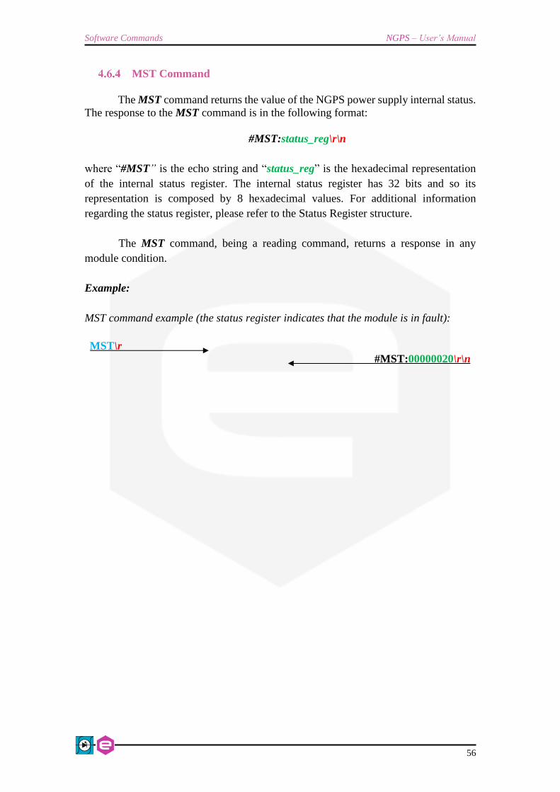
MST Command
The MST command returns the value of the NGPS power supply internal status.
The response to the MST command is in the following format:
#MST:status_reg\r\n
where “#MST” is the echo string and “status_reg” is the hexadecimal representation
of the internal status register. The internal status register has 32 bits and so its
representation is composed by 8 hexadecimal values. For additional information
regarding the status register, please refer to the Status Register structure.
The MST command, being a reading command, returns a response in any
module condition.
Example:
MST command example (the status register indicates that the module is in fault):
MST\r
#MST:00000020\r\n

NGPS – User’s Manual Software Commands
57
MRESET Command
The MRESET command has to be used in order to perform a complete reset of
the module status register. This is needed, for example, to enable the channel output
again after a fault condition has been fixed.
Replies from the NGPS to a MRESET command are in the form “#AK\r\n” –
when the command is correctly executed - or “#NAK:xx\r\n”, when the command
cannot be executed (“xx” is the error code). The complete list of the error codes is
shown in the Error Table.
Examples:
MRESET command example:
MRESET\r
#AK\r\n
MRESET command example when the module is in local mode:
MRESET\r
#NAK:15\r\n

Software Commands NGPS – User’s Manual
58
MRI Command
The MRI command returns the readback value of the power supply actual output
current.
The readback current value is represented with 6-digit precision. Replies from
the power supply to this command are in the following format:
#MRI:current_value\r\n
where “#MRI” is the echo string, “current_value” is the output current value readback
in Ampere [A].
Example:
MRI command example:
MRI\r
#MRI:22.123456\r\n

NGPS – User’s Manual Software Commands
59
MRV Command
The MRV command returns the readback value of the power supply actual
output voltage.
The voltage readback value is represented with 6-digit precision. Replies from
the power supply to this command are in the following format:
#MRV:voltage_value\r\n
where “#MRV” is the echo string, “voltage_value” is the output voltage value readback
in Volts [V].
Example:
MRV command example:
MRV\r
#MRV:10.123456\r\n

Software Commands NGPS – User’s Manual
60
LOOP Command
The LOOP command can be used in order to select the mode of loop control of
the NGPS unit. There are two possible modes of operation:
• Constant Current (c.c.),
• Constant Voltage (c.v.).
To set the mode of operation the following commands has to be used:
LOOP:mode\r\n
where “mode” is a single char indicating the mode of operation:
• “I” for Constant Current (c.c.) mode and
• “V” for Constant Voltage (c.c.) mode.
Replies from the NGPS to a LOOP set are in the form “#AK\r\n” – when the
command is correctly executed - or “#NAK:xx\r\n”, when the command cannot be
executed (“xx” is the error code). The two modes of operation can be changed only
when the module is turned OFF.
To read the current used loop mode of operation the query command:
“LOOP:?” has to be used. The response to the “LOOP:?” query command is in the
following format:
#LOOP:mode \r\n
where “#LOOP” is the echo string, “mode” is a single character indicating the loop
mode (“I” for constant current mode and “V” for constant voltage mode).
Examples:
LOOP set example to set the constant current mode:
LOOP:I\r
#AK\r\n
LOOP set example when the module is ON:
LOOP:V\r
#NAK:09\r\n

NGPS – User’s Manual Software Commands
61
LOOP query example when the module is in constant voltage (c.v.) mode:
LOOP:?\r
#LOOP:V\r\n

Software Commands NGPS – User’s Manual
62
MWI Command
The MWI command can be used to set the output current value when the module
is in the constant current mode (see LOOP Command). This command is usually needed
when running feedback-related applications and for small changes in the output current.
The use of this command is alternative to the MWIR Command (ramping
current command), which is advised for regular use.
This command has the following format:
MWI:current_setpoint\r\n
where “current_setpoint” is the desired current set-point expressed in Ampere [A].
Replies from the NGPS to a MWI set are in the form “#AK\r\n” – when the
command is correctly executed - or “#NAK:xx\r\n”, when the command cannot be
executed (“xx” is the error code).
To read last applied current setpoint the query command: “MWI:?” has to be
used. The response to this query command is in the following format:
#MWI:current_setpoint\r\n
where “#MWI” is the echo string, “current_setpoint” is the last applied current setpoint
expressed in Ampere [A].
Examples:
MWI set example, with current setpoint +1.52 A:
MWI:1.52\r
#AK\r\n
MWI set example when the module is OFF:
MWI:1.52\r
#NAK:13\r\n
MWI query example:
MWI:?\r
#MWI:1.52\r\n

NGPS – User’s Manual Software Commands
63
MWV Command
The MWV command can be used to set the output voltage value when the
constant voltage mode is used (see LOOP Command). The use of this command is
alternative to the MWVR Command (ramping voltage command).
This command has the following format:
MWV:voltage_setpoint\r\n
where “voltage_setpoint” is the desired voltage set-point expressed in Volts [V].
Replies from the NGPS to a MWV set are in the form “#AK\r\n” – when the
command is correctly executed - or “#NAK:xx\r\n”, when the command cannot be
executed (“xx” is the error code).
To read last applied voltage setpoint the query command: “MWV:?” has to be
used. The response to this query command is in the following format:
#MWV:voltage_setpoint \r\n
where “#MWI” is the echo string, “voltage_setpoint” is the last applied current setpoint
expressed in Volts [V].
Examples:
MWV set example, with current setpoint +10.525 V:
MWV:10.525\r
#AK\r\n
MWV set example when the module is OFF:
MWV:10.525\r
#NAK:13\r\n
MWV query example:
MWV:?\r
#MWV:10.525\r\n

Software Commands NGPS – User’s Manual
64
MWIR Command
The MWIR command can be used to perform a ramp to the given current
setpoint. This command can be used, when the constant current mode is selected (see
LOOP Command).
The use of this command is alternative to the MWI Command. The difference
between the MWI command and the MWIR command is that the first one generates a
direct change in output current characterized by the PID regulator parameters (the
command is ideally suited for small output current changes and feedback purposes)
while the second one makes the power supply go from the previous to the actual current
value performing a ramp, defined by a slew-rate in [A/s].
The default value of the slew-rate is stored in the parameter table and it can be
read and modified using the Configuration Commands.
To dynamically change the current slew-rate value it is possible using the MSRI
Command. This command has the following format:
MWIR:final_ramp_setpoint\r\n
where “final_ramp_setpoint” is the final current value expressed in Ampere [A] to
which the power unit will ramp with the defined slew-rate.
Replies from the NGPS to a MWIR set are in the form “#AK\r\n” – when the
command is correctly executed - or “#NAK:xx\r\n”, when the command cannot be
executed (“xx” is the error code).
To read the selected final ramp setpoint, the query command: “MWIR:?” has to
be used. The response to this query command is in the following format:
#MWIR:final_ramp_setpoint\r\n
where “#MWIR” is the echo string and “final_ramp_setpoint” is the final ramp
setpoint expressed in Ampere [A].
Examples:
MWIR set example, with final ramp setpoint +10.5 A:
MWIR:10.5\r
#AK\r\n
MWIR set example when the module is OFF:
MWIR:10.5\r
#NAK:13\r\n
MWIR query example:

NGPS – User’s Manual Software Commands
65
MWIR:?\r
#MWIR:10.5\r\n

Software Commands NGPS – User’s Manual
66
MSRI Command
The MSRI command can be used to dynamically change the value of the current
ramp slew-rate. The default slew-rate, used at start-up of the unit, is the value stored in
the parameters table.
This command has the following format:
MSRI:slew_rate\r\n
where “slew_rate” is slew-rate for the current ramp expressed in Ampere per second
[A/s].
Replies from the NGPS to a MSRI set are in the form “#AK\r\n” – when the
command is correctly executed - or “#NAK:xx\r\n”, when the command cannot be
executed (“xx” is the error code).
To read the current used slew-rate for the current ramp, the query command:
“MSRI:?” has to be used. The response to this query command is in the following
format:
#MSRI:slew_rate\r\n
where “#MSRI” is the echo string and “slew_rate” is the slew-rate value used for the
current ramp expressed in Ampere per second [A/s].
Examples:
MSRI example, to set the current slew-rate to 10 A/s:
MSRI:10\r
#AK\r\n
MSRI set example when the NGPS is in local mode:
MSRI:10\r
#NAK:15\r\n
MSRI query example:
MSRI:?\r
#MSRI:10\r\n

NGPS – User’s Manual Software Commands
67
MWVR Command
The MWVR command can be used to perform a ramp to the given voltage
setpoint. This command can be used, when the constant voltage mode is selected (see
LOOP Command).
The use of this command is alternative to the MWV Command. The difference
between the MWV command and the MWVR command is that the first one generates a
direct change in output voltage characterized by the PID regulator parameters while the
second one makes the power supply go from the previous to the actual current value
performing a ramp, defined by a slew-rate in [V/s].
The default value of the voltage slew-rate is stored in the parameter table (see
the Configuration Commands).
To dynamically change the slew-rate value it is possible to use the MSRV
Command.
This command has the following format:
MWVR:final_ramp_setpoint\r\n
where “final_ramp_setpoint” is the final voltage value expressed in Volts [V] to which
the power unit will ramp with the defined slew-rate.
Replies from the NGPS to a MWVR set are in the form “#AK\r\n” – when the
command is correctly executed - or “#NAK:xx\r\n”, when the command cannot be
executed (“xx” is the error code).
To read the selected final ramp setpoint, the query command: “MWVR:?” has
to be used. The response to this query command is in the following format:
#MWVR:final_ramp_setpoint\r\n
where “#MWVR” is the echo string and “final_ramp_setpoint” is the final ramp
setpoint expressed in Volts [V].
Examples:
MWVR set example, with final ramp setpoint +15.2 A:
MWVR:15.2\r
#AK\r\n
MWVR set example when the module is OFF:
MWVR:15.2\r
#NAK:13\r\n

Software Commands NGPS – User’s Manual
68
MWVR query example:
MWVR:?\r
#MWVR:15.2\r\n

NGPS – User’s Manual Software Commands
69
MSRV Command
The MSRV command can be used to dynamically change the value of the
voltage ramp slew-rate. The default slew-rate, used at start-up of the unit, is the value
stored in the parameters table.
This command has the following format:
MSRV:slew_rate\r\n
where “slew_rate” is slew-rate for the voltage ramp expressed in Volts per second [V/s].
Replies from the NGPS to a MSRV set are in the form “#AK\r\n” – when the
command is correctly executed - or “#NAK:xx\r\n”, when the command cannot be
executed (“xx” is the error code).
To read the current used slew-rate for the voltage ramp, the query command:
“MSRV:?” has to be used. The response to this query command is in the following
format:
#MSRV:slew_rate\r\n
where “#MSRV” is the echo string and “slew_rate” is the slew-rate value used for the
voltage ramp expressed in Volts per second [V/s].
Examples:
MSRV example, to set the current slew-rate to 10 V/s:
MSRV:10\r
#AK\r\n
MSRV set example when the NGPS is in local mode:
MSRV:10\r
#NAK:15\r\n
MSRV query example:
MSRV:?\r
#MSRV:10\r\n

Software Commands NGPS – User’s Manual
70
MRT Command
The MRT command returns the value of the temperature directly measured on
the output stage heatsink.
The response to the MRT command is in the following format:
#MRT:temperature\r\n
where “#MRT” is the echo string and “temperature” is the temperature value expressed
in Celsius [°C]. The MRT command, being a reading command, returns a response in
any module condition.
Example:
MRT command example:
MRT\r
#MRT:37.4\r\n

NGPS – User’s Manual Software Commands
71
MRW Command
The MRW command returns the actual value of the estimated active power
applied to the connected load.
The response to the MRW command is in the following format:
#MRW:active_power\r\n
where “#MRW” is the echo string and “active_power” is the output active power
readback expressed in Watts [W], estimated as the product of the output voltage and
output current readbacks. The MRW command, being a reading command, returns a
response in any module condition.
Example:
MRW command example:
MRW\r
#MRW:100.45\r\n

Software Commands NGPS – User’s Manual
72
MGC Command
The MGC command returns the readback value of the actual leakage current of
the NGPS unit.
The response to the MGC command is in the following format:
#MGC:leakage_current\r\n
where “#MGC” is the echo string and “leakage_current” is the earth leakage current,
expressed in Ampere [A].
When a leakage fault condition is tripped, the MGC command will return the
value of the max leakage current that tripped the fault. To return to the normal behavior
of the read command, the module status has to be reset (see MRESET Command).
The MGC command, being a reading command, returns a response in any
module condition.
Example:
MGC command example for a 60mA ground leakage current:
MGC\r
#MGC:0.06\r\n

NGPS – User’s Manual Software Commands
73
MRID Command
The MRID command returns the NGPS identification name string. This
description is useful in case that there are numerous units installed and it is possible to
give a description for each unit (for example the name of the load on which the unit is
connected). This information is also displayed on the local display.
The response to the MRID command is in the following format:
#MRID:ngps_identification\r\n
where “#MRID” is the echo string and “ngps_identification” is the module
identification string. The identification string is stored in the parameters table and so it
is possible to change it using the Configuration Commands.
Example:
MRID example with the module identification “SkewMag1.3”:
MRID\r
#MRID:DIPOLE1.3\r\n

Software Commands NGPS – User’s Manual
74
4.7 Configuration Commands
In the following section are described the software commands that allow to read,
set and store the working parameters of the NGPS unit.
The MRG Command and MWG Command allow to read or modify the working
parameters. The write-access to several parameters is password protected and certain
parameters are read only and so it is not possible to modify them. To change the
password privileges use the PASSWORD Command. In order to save the parameter on
the on-board non-volatile memory, the MSAVE Command has to be used.
The complete list of the configuration parameters, their field index and the
access privileges are hereafter shown:
Parameter
# Access Privileges Parameter Name
#0 Read Only Firmware ID
#1 Read Only PS Model
#2 Read Only Serial Number
#3 Read Only MAC Ethernet
#4 Read Only MAC SFP #1
#5 Read Only MAC SFP #2
#6 - #8 / Reserved
#9 Read Only Calibration date
#10 Read Only Current Calibration Parameter a
#11 Read Only Current Calibration Parameter b
#12 Read Only Current Calibration Parameter c
#13 Read Only Current Calibration Parameter d
#14 Read Only Voltage Calibration Parameter a
#15 Read Only Voltage Calibration Parameter b
#16 Read Only Voltage Calibration Parameter c
#17 Read Only Voltage Calibration Parameter d
#18 Read Only DC Link Calibration Parameter a
#19 Read Only DC Link Calibration Parameter b
#20 Read Only AC Link Calibration Parameter a
#21 Read Only AC Link Calibration Parameter b
#22 Read Only Current Leakage Calibration Parameter a
#23 Read Only Current Leakage Calibration Parameter b
#24 Read Only Analog Input Calibration Parameter a
#25 Read Only Analog Input Calibration Parameter b
#26 Read Only Primary Current Calibration Parameter a
#27 Read Only Primary Current Calibration Parameter b
#28 - #29 / Reserved
#30 User Module Identification
#31 User Default Current Slew Rate [A/s]

NGPS – User’s Manual Software Commands
75
Parameter
# Access Privileges Parameter Name
#32 User Default Voltage Slew Rate V [V/s]
#33 - #39 / Reserved
#40 User PID I: Kp_v
#41 User PID I: Ki_v
#42 User PID I: Kd_v
#43 User PID I: Kp_i
#44 User PID I: Ki_i
#45 User PID I: Kd_i
#46 User PID I: Upper Limit Acc_v
#47 User PID I: Lower Limit Acc_v
#48 - #59 / Reserved
#60 User PID V: Kp_i
#61 User PID V: Ki_i
#62 User PID V: Kd_i
#63 User PID V: Kp_v
#64 User PID V: Ki_v
#65 User PID V: Kd_v
#66 User PID V: Upper Limit Acc_i
#67 User PID V: Lower Limit Acc_i
#68 - #74 / Reserved
#75 Admin Max Transformer Temperature
#76 Admin Min DCCT Shunt Temperature
#77 Admin Max DCCT Shunt Temperature
#78 - #79 / Reserved
#80 Admin Max Current Setpoint [A]
#81 Admin Max Voltage Setpoint [V]
#82 Admin Max Heatsink Temperature
#83 Admin Min DC-link Threshold
#84 Admin Earth Leakage Limit
#85 / Reserved
#86 Admin Current Regulation Fault Limit [A]
#87 Admin Voltage Regulation Fault Limit [A]
#88 Admin Regulation Fault Intervention Time [s]
#89 Admin Primary Current Limit
#90 Admin Interlock Enable Mask
#91 Admin Interlock Activation State
#92 Admin Interlock #1 intervention time [ms]
#93 Admin Interlock #1 name
#94 Admin Interlock #2 intervention time [ms]
#95 Admin Interlock #2 name
#96 Admin Interlock #3 intervention time [ms]

Software Commands NGPS – User’s Manual
76
Parameter
# Access Privileges Parameter Name
#97 Admin Interlock #3 name
#98 Admin Interlock #4 intervention time [ms]
#99 Admin Interlock #4 name
Table 17: Parameters table
MRG Command
The MRG command returns the value stored in the given parameter number.
The correct form for the reading request is as follow:
MRG:parameter_index\r\n
where “parameter_index” is the index of the parameter to be read. The response to the
MRG command is in the following format:
#MRG:parameter_index:parameter_value\r\n
where “#MRG” is the echo string, “parameter_index” is the parameter’s index and
“parameter_value” is the parameter caption. The NGPS replies with “#NAK:xx\r\n”,
when the command cannot be executed (“xx” is the error code) – for example if the
given parameter is out of the permitted range.
Examples:
MRG example of the PS-Model (parameter #1):
MRG:1\r
#MRG:1:NGPS 100-50\r\n
MRG example of read a not valid parameter’s index (parameter # -1):
MRG:-1\r
#NAK:03\r\n

NGPS – User’s Manual Software Commands
77
MWG Command
The MWG command lets users write a desired value in the given parameters
index.
MWG:parameter_index:parameter_value\r\n
where “parameter_index” is the parameter’s index and “parameter_value” is the
content to be written.
Replies from the NGPS to a MWG write are in the form “#AK\r\n” – when the
command is correctly executed - or “#NAK:xx\r\n”, when the command cannot be
executed (“xx” is the error code).
After a MWG command the values are immediately applied, but they are not
stored in the internal memory. To store the modified parameters in the non-volatile
internal memory it is necessary to use the MSAVE Command.
Examples:
MWG example of the Module ID (parameter #30)
MWG:30:MAGNET A\r
#AK \r\n
MWG write example to the read-only field #1 (PS Model):
MWG:1:MAGNET A\r
#NAK:05\r\n

Software Commands NGPS – User’s Manual
78
PASSWORD Command
The PASSWORD command can be used to unlock or lock the access to the
protected parameter fields.
Several parameters are protected in order not to let inexperienced users to
change some power supply parameters that might compromise the correct operation of
the module. See the Parameters table for further details regarding the password-
protected cells (parameters with User access privileges are not password protected;
parameters with Admin access privileges are password protected; parameters with Read
Only access privileges cannot be modified).
The correct format for this command is as follows:
PASSWORD:password_word\r\n
where “password_word” is the password to lock or unlock the protected parameter
fields, that can be:
• “PS-ADMIN” to receive the Admin access privileges and unlock the protected
parameter fields;
• “LOCK” to return to User access privileges and lock the protected parameters
fields.
Replies from the NGPS to a PASSWORD command are in the form “#AK\r\n”
– when the command is accepted - or “#NAK:xx\r\n”, when the command is not
accepted (“xx” is the error code). When a wrong password word is received, the unit
replies with a “#NAK:07\r\n” (error code 07 – invalid password) and locks the
protected parameter fields.
To read the current privileges level the following query command can be used:
“PASSWORD:?”. The response to this query command is in the following format:
#PASSWORD:privileges_level\r\n
where “#PASSWORD” is the echo string and “privileges_level” is the string indicating
the privileges level.
The privileges level “ADMIN” indicates that the user is able to modify the
protected parameter fields, otherwise “USER” indicates that the uses is able to modify
only the not protected parameter fields.
The password to unlock password-protected cells is:
PS-ADMIN

NGPS – User’s Manual Software Commands
79
Examples:
PASSWORD example of correct password word (unlock the protected cells):
PASSWORD:PS-ADMIN\r
#AK \r\n
PASSWORD example of correct password word (lock the protected cells):
PASSWORD:LOCK\r
#AK \r\n
PASSWORD example of wrong password word:
PASSWORD:CAENELS\r
#NAK:07 \r\n
PASSWORD access level query:
PASSWORD:?\r
#PASSWORD:ADMIN\r\n

Software Commands NGPS – User’s Manual
80
MSAVE Command
The MSAVE command can be used store the parameter fields in the non-volatile
internal memory. If the parameter fields are not saved, they will be lost at power-off of
the power supply.
Replies from the NGPS to a MSAVE are in the form “#AK\r\n” – when the
command is correctly executed - or “#NAK:xx\r\n”, when the command cannot be
executed (“xx” is the error code).
Example:
MSAVE example:
MSAVE\r
#AK \r\n
UPMODE Command
The UPMODE command can be used to access the analog control of the unit or
to re-put the unit in standard (Ethernet) control.
The two commands are UPMODE:ANALOG to set the unit in analog control
or UPMODE:NORMAL to set the unit in Ethernet control.
Replies from the NGPS to a UPMODE are in the form “#AK\r\n” – when the
command is correctly executed - or “#NAK:xx\r\n”, when the command cannot be
executed (“xx” is the error code).
Example:
UPMODE example:
UPMODE:ANALOG\r
#AK \r\n

NGPS – User’s Manual NGPS Utilities
81
SETFLOAT Command
The SETFLOAT command can be used to set the system in floating mode.
The two commands are SETFLOAT:F to set the unit in floating mode or
SETFLOAT:N to set the unit as grounded. Earth fuse must be disconnected to operate
the unit in floating mode.
Replies from the NGPS to a SETFLOAT are in the form “#AK\r\n” – when the
command is correctly executed - or “#NAK:xx\r\n”, when the command cannot be
executed (“xx” is the error code).
Replies to command SETFLOAT:? will be “#F\r\n” or “#N\r\n” respectively
if the module current setting is in floating mode or standard one.
Example:
SETFLOAT example:
SETFLOAT:F\r
#AK \r\n

NGPS Utilities NGPS – User’s Manual
82
5. NGPS Utilities
The NGPS Utilities allow a user-friendly and fast access to the functionalities and
configuration of the NGPS unit.
Two different software are available for operation with the NGPS power supply:
“Device Manager” and “Visual PS”. Both utilities can be downloaded from the
CAENels website www.caenels.com. An overview of both utilities is given in the next
sections.
5.1 Device Manager
The “Device Manager” software can be used to detect all the NGPS devices
connected to the local network and their network configuration.
The “Device Manager” is available for Windows and Linux platform. The
system requirements are:
• Windows minimum system requirements:
Windows® XP or newer
Intel® or equivalent processor
70 MB available HD space
Ethernet network card
• Linux minimum system requirements:
Linux kernel 2.2.x or newer
Intel® or equivalent processor
70 MB available HD space
Ethernet network card

NGPS – User’s Manual NGPS Utilities
83
Searching for connected devices
The following steps have to be performed in order to perform a search of all the
NGPS units connected to the local network:
- install the “Device manager” software;
- launch the software;
- perform a scan to discover the connected NGPS device(s) by clicking the
“Scan” button as indicated in Figure 24. If there are multiple available
connections it is possible to select the network/networks to be scanned in the
“Selected network interfaces” window available under the “Options” menu. All
the information about the selected devices are shown in the right side of the
main window.
Figure 24: Device Manager - Main interface
Make sure that the firewall is not preventing communication between your
computer and the NGPS unit(s). The “Device manager” uses UDP port 30719 to find
the device, so ensure that the UDP traffic is allowed in both directions on this port.
Scan the selected
network interface(s)
Found device(s)
Device information

NGPS Utilities NGPS – User’s Manual
84
Device Configuration
The software allows also to change the Network configuration of the found
device(s) in the local network.
In order to change the network configuration of the unit it is necessary to select the
desired device and click on the “Change device configuration” button in the main
window as shown in Figure 25. The configurable Network options are:
Device IP address;
TCP/IP communication port;
Subnet mask;
Gateway.
To apply the changes on the device configuration it is necessary to edit the
corresponding fields and then to click on the “Save” button. A screenshot of a sample
device configuration is shown in the following picture:
Figure 25: Device Manager - Change device configuration
Device configuration

NGPS – User’s Manual NGPS Utilities
85
5.2 Visual PS
The VISUAL PS software makes it easy to remote control the main features of the
NGPS series using a Graphic User Interface (GUI).
The software is developed using Qt, which is a cross-platform application and UI
framework with APIs for C++ programming. The software is available for Windows
platform. The system requirements are as follows:
• Windows minimum system requirements:
Windows® XP or newer
Intel® or equivalent processor
30 MB available HD space
Ethernet network card
Power Supply IP
To communicate with a NGPS power unit it is necessary to set its IP address and
its port. This operation can be made by using the module IP address window, accessible
by clicking the first “Set IP” icon of the Visual PS Toolbar.
Figure 26: Visual PS – Set IP

NGPS Utilities NGPS – User’s Manual
86
To establish the connection with the module, it is necessary to click on the
“Connection” icon. Once the communication is established it is possible to configure
the unit and monitor its status.
Main windows
The Visual PS main window is organized in the following sections:
Figure 27: Visual PS – Main Window
• Unit Controls: allow to Switch ON/OFF the unit and to Reset its status
register (in case of a fault).
• Regulation mode: allows to select the mode of operation. The available
modes are: “Constant Voltage” mode or “Constant Current” mode. The
regulation mode can be changed only when the unit is switched OFF.
• Voltage/Current Set section: this section allows to set the Voltage (for
the “Constant Voltage” mode) or Current (for the “Constant Current”
mode) setpoint. To apply a setpoint it is necessary to click on the Ramp
or Set button. The Ramp button performs a ramp to the selected setpoint,
otherwise the Set button applies directly the selected setpoint.

NGPS – User’s Manual NGPS Utilities
87
• General information: indicates some information regarding the
connected unit, like the model and its serial number.
• Unit status: indicates some information regarding output status,
temperature, current leakage, unit control (local or remote) and fault
status. By clicking on the fault status indicator it is possible to visualize a
detailed fault status windows.
• Output monitor: indicates the actual output voltage, current and power.
Unit Configuration
To display the configuration Window, click on the Configuration button on the
main Toolbar. From this window it is possible to configure the unit. Several fields are
password protected. To have the access to the password protected fields it is necessary
to insert the correct password word. For additional inflammation regarding the
password protected cells and the memory structure, please refer to Configuration
Commands section. The Configuration Window is divided in the following tabs:
• General tab: shows the general information about the unit as the name
of the unit, its model, firmware version, serial number and the
calibration date.
• Interlock and Limit tab: from this tab the user can:
o display and edit the names, direction, status (enabled or
disabled) and intervention time of the available external
interlocks,
o visualize and edit the module limits (which generate a fault
condition) as: the maximum allowable temperature, min DC-link
voltage, Leakage current limit etc.
• PID tab: from this tab it is possible to edit the PID regulators parameters
– i.e. proportional, derivative and integral terms
• File tab: in this tab the user can display, edit and save the content of the
unit memory

NGPS Utilities NGPS – User’s Manual
88
Figure 28: Visual PS – Configuration Window
Firmware Update
In order to update the NGPS unit firmware it is necessary to click on the
Firmware Update button on the main toolbar. From the Firmware Update window select
the desired firmware file (*.udpt extension) and click on the Upload Firmware button.
The update procedure can take several minutes for the firmware update procedure.
Access privileges
and password set
Configuration Tabs

NGPS – User’s Manual NGPS Utilities
89
Figure 29: Visual PS – Firmware Update

Mechanical Dimensions NGPS – User’s Manual
90
6. Mechanical Dimensions
The mechanical dimensions of the NGPS unit are hereafter presented in Figure
30:
Figure 30: NGPS Mechanical Drawings

NGPS – User’s Manual Technical Specifications
91
7. Technical Specifications
The main technical specifications for the NGPS models are hereafter presented:
Technical Specifications NGPS
Output current range
120 A (NGPS 120-50)
140 A (NGPS 140-50)
150 A (NGPS 150-60)
200 A (NGPS 200-50)
Output voltage range
50 V (NGPS 120-50 / NGPS 140-50)
60 V (NGPS 150-60)
50 V (NGPS 200-50)
Maximum output power
6 kW (NGPS 120-50)
7 kW (NGPS 140-50)
9 kW (NGPS 150-60)
10 kW (NGPS 120-50)
Regulation Type Current- or Voltage- Control
Current and Voltage Setting 18 bit
Current and Voltage Readback 20 bit
Output insolation 500 V
Power Factor > 0.93
Efficiency > 90%
Max Current/Voltage update rate 10 kHz (over SFP)
Closed-loop Bandwidth > 100 Hz (C.C. mode)
> 200 Hz (C.V. mode)
Accuracy < 0.01% (0.005% upon request) (C.C. mode)
< 0.05% (C.V. mode)
Line Regulation ±5 ppm / FS
Load Regulation ±5 ppm / FS
Remote Sensing Compensation up to 2V
Cooling Forced Air Convection (front-to-rear)
Temperature Stability 5 ppm/K (C.C. mode) (1ppm/K upon request)
50 ppm/K (C.V. mode)
Communication interfaces 1x Ethernet 10/100/1000 TCP-IP
2x SFP ports
Itnernal Interlocks
Over-Temperature
MOV Input Over-Voltage
Main circuit-breaker for Over-Current
Output Free-wheeling diodes

Technical Specifications NGPS – User’s Manual
92
Technical Specifications NGPS
Output Over-current and Over-Voltage
Earth current leakage
Mains fault
External Interlocks/States Magnetic relay
Solid-state relay
Modularity Parallel connection (up to 4)
Drivers EPICS
Extra-features
Point-by-point current waveform
User-definable interlock thresholds, active levels and timings
Firmware remote update
Dimensions 19” x 3U x 600 mm
Input Ratings 208 VAC (“E”) Three-phase 50/60 Hz
400 VAC (“A”) Three-phase 50/60 Hz
Weight 28 kg
Operating Temperature 0…40 °C
Operating current range
(rated stability and accuracy) 2 - 100 %
Table 18: Technical Specifications