nfpa standards development site second … standards development site second draft report ... nfpa...
TRANSCRIPT

NFPA 1192®, Standard on Recreational Vehicles, 2011 Edition
NFPA STANDARDS DEVELOPMENT SITESECOND DRAFT REPORTClosing Date: July 19, 2013 NOTE: All Public Comment must be received by 5:00 pm EST/EDST on the published Closing Date.
Quick PrintChapter 1 Administration
1.1* Scope.
This standard shall cover fire and life safety criteria for recreational vehicles.
1.2 Purpose.
The purpose of this standard shall be to provide the minimum criteria for recreational vehicles that are considered necessary toprovide protection from loss of life from fire and explosion.
1.3 Application.
1.3.1*
The requirements of this standard shall be applied to all new recreational vehicles.
1.3.2
This standard shall not be applied as a stand-alone design specification or instruction manual.
1.3.3
This standard shall apply to new recreational vehicles manufactured on or after September 1, 2014.
1.4 Retroactivity.
This standard shall not be applied retroactively.
1.5 Equivalency.
The provisions of this standard shall not be intended to prevent the use of any material, method of construction, or installationprocedure not specifically prescribed by this standard, provided any such alternate is acceptable to the authority having jurisdiction.The authority having jurisdiction shall require that sufficient evidence be submitted to substantiate any claims made regarding thesafety of such alternatives.
1.6* Use of International System of Units (SI).
In some cases SI equivalents to U.S. customary units have been inserted in this standard. Where used, the conversions have beenrounded to the number of digits commensurate with their intended precision. Use of the SI units herein is in accordance with theManual of Style for NFPA Technical Committee Documents. Alternating usage of U.S. and SI units to determine distance, size(capacity), or dimensions shall not be used. Where SI equivalents are not given, it is because the U.S. units shall be employed byanyone enforcing this standard.
http://submittals.nfpa.org/TerraViewWeb/ContentFetcher?contentId=/Te...
1 of 1 5/14/2014 9:42 AM

NFPA 1192®, Standard on Recreational Vehicles, 2011 Edition
NFPA STANDARDS DEVELOPMENT SITESECOND DRAFT REPORTClosing Date: July 19, 2013 NOTE: All Public Comment must be received by 5:00 pm EST/EDST on the published Closing Date.
Quick Print
SR-21 Hide Legislative
PCs [1] SR-5 Hide Legislative
PCs [1] SR-4 Hide Legislative
PCs [1] SR-15 Hide Legislative
Chapter 2 Referenced Publications
2.1 General.
The documents or portions thereof listed in this chapter are referenced within this standard and shall be considered part of therequirements of this document.
2.2 NFPA Publications.
National Fire Protection Association, 1 Batterymarch Park, Quincy, MA 02169-7471.
NFPA 10, Standard for Portable Fire Extinguishers, 2010 2013 edition.
NFPA 58, Liquefied Petroleum Gas Code, 2011 2014 edition.
NFPA 70®, National Electrical Code®, 2011 2014 edition.
2.3 Other Publications.
2.3.1 ANSI Publications.
American National Standards Institute, Inc., 25 West 43rd Street, 4th Floor, New York, NY 10036.
ANSI B1.20.1, Pipe Threads, General Purpose (Inch), 2001.
ANSI TSIC-1 Recommended Practice, Process Controls for Assembly of Wheels on Trailers, 2008.
ANSI Z535 , Safety Alerting Standard Series, 2011.
ANSI Z97.1, Glazing Materials Used in Buildings, Safety Performance Specifications and Methods of Test, 1994.
ANSI Z535, Safety Alerting Standard Series , 2011.
2.3.2 ASME Publications.
American Society of Mechanical Engineers, Three Park Avenue, New York, NY 10016-5990.
ASME Boiler and Pressure Vessel Code, Section VIII, Division I, Rules for Construction of Unfired Pressure Vessels, 2004.
ANSI/ASME A.112.19.2, Vitreous China Plumbing Fixtures and Hydraulic Requirements for Water Closets and Urinals, 2003.
2.3.3 ASTM Publications.
ASTM International, 100 Barr Harbor Drive, P.O. Box C700, West Conshohocken, PA 19428-2959.
ASTM A 53/A53M, Standard Specifications for Pipe, Steel, Black and Hot-Dipped, Zinc-Coated Welded and Seamless, 2010.
ASTM A 539, Standard Specifications for Electric-Resistance Welded Coiled Steel Tubing for Gas and Fuel Oil Lines, 1999(withdrawn 2004).
ASTM B 88, Standard Specifications for Seamless Copper Water Tube, 2009.
ASTM B 280, Specifications for Seamless Copper Tube for Air Conditioning and Refrigeration Field Service, 2008.
ASTM E 84, Standard Test Method for Surface Burning Characteristics of Building Materials, 2011c 2012b .
ASTM E 162, Standard Test Method for Surface Flammability of Materials Using a Radiant Heat Energy Source, 2011a 2012a .
2.3.4 CAN/ULC Publications.
Underwriters Laboratories of Canada, 7 Underwriters Road, Toronto, Ontario, Canada MIR 3A9 ON, MIR 3A9, Canada .
CAN/ULC-S508, Standard for the Rating and Fire Testing of Fire Extinguishers,2002 2004, revised 2009 (including amendments 1,2, and 3)
CAN/ULC S504, Standard for Dry Chemical Fire Extinguishers, 2002 (including Amendments 2012 (including amendments 1, 2,and 3).
2.3.5 CGA Publications.
Compressed Gas Association, 4221 Walney Road, 5th Floor, Chantilly, VA 20151-2923.
CGA V-1, Compressed Gas Cylinder Valve Outlet and Inlet Connections , 2003.
http://submittals.nfpa.org/TerraViewWeb/ContentFetcher?contentId=/Te...
1 of 3 5/14/2014 9:43 AM

PCs [1]
PCs [1] SR-16 Hide Legislative
2.3.5 CSA Publications.
Canadian Standards Association, 5060 Spectrum Way, Mississauga, ON, L4W 5N6, Canada.
CAN/CSA 6–19, Residential Carbon Monoxide Alarming Devices, 2001 (reaffirmed 2006).
CSA B51, Boiler, Pressure Vessel, and Pressure Piping Code, 2009.
CAN3-D313, Trailer Running Gear, 1985 (reaffirmed 2012).
2.3.6 IAPMO Publications.
International Association of Plumbing and Mechanical Officials, 4755 E. Philadelphia Street, Ontario, CA 91761.
ANSI/IAPMO Z124.4, Plastic Water Closet Bowls and Tanks, 2006.
2.3.7 NATM Publications.
National Association of Trailer Manufacturers (NATM), 1320 SW Topeka Blvd., Topeka, KS 66612-1817.
ANSI TSIC-1 Recommended Practice, Process Controls for Assembly of Wheels on Trailers , 2008.
2.3.8 RVIA Publications.
Recreation Vehicle Industry Association, 1896 Preston White Drive, Reston, VA 20191.
ANSI/RVIA, Low Voltage Systems in Conversion and Recreational Vehicles, 2011.
2.3.9 SAE Publications.
Society of Automotive Engineers, 400 Commonwealth Drive, Warrendale, PA 15096.
SAE J30R7, Fuel and Oil Hoses, Standard, 1998.
SAE J476, Dryseal Pipe Threads, 1961.
SAE J533, Flares for Tubing, Standard, 1999.
SAE J684, Trailer Couplings, Hitches, and Safety Chains — Automotive Type, Standard, 2005.
SAE J1128, Low Voltage Cable , 2012.
SAE J1508, Hose Clamp Specifications, 1997.
SAE J2638, Fifth Wheel and Gooseneck Attachment Performance Up to 13 608/Kg (30 000/Lb) Trailer Gvw, 2003.
SAE Handbook, 2007.
2.3.10 TC Publications.
Transport Canada, 330 Sparks Street, Ottawa, ON K1A 0N5, Canada.
TSD 108, Motor Vehicle Regulations, Lighting System and Retroreflective Devices , 2007.
2.3.11 UL Publications.
Underwriters Laboratories Inc., 333 Pfingsten Road, Northbrook, IL 60062-2096.
ANSI/UL 21, Standard for LP-Gas Hose, 2007, Revised revised 2010.
ANSI/UL 94, Standard for Safety Test for Flammability of Plastic Materials for Parts in Devices and Appliances, 1996,Revised revised 2010 2012 .
ANSI/UL 125, Standard for Flow Control Valves for Anhydrous Ammonia and LP-Gas, 2009, Revised revised 2011.
ANSI/UL 144, Standard for LP-Gas Regulators, 1999, Revised 2010 2012 .
ANSI/UL 181, Standard for Safety Factory-Made Air Ducts and Air Connectors, 2005, Revised revised 2008.
ANSI/UL 217, Standard for Single and Multiple Station Smoke Alarms, 2006, Revised revised 2011 2012 .
ANSI/UL 299, Dry Chemical Extinguishers, 2012.
ANSI/UL 330, Standard for Hose and Hose Assemblies for Dispensing Flammable Liquids, 2009, Revised revised 2011.
ANSI/UL 484, Standard for Room Air Conditioners, 2007, Revised revised 2011 2012 .
ANSI/UL 569, Standard for Pigtails and Flexible Hose Connectors for LP-Gas, 1995, Revised revised 2009.
ANSI/UL 723, Test of Surface Burning Characteristics of Burning Materials, 2008, revised 2010.
ANSI/UL 842, Standard for Valves for Flammable Liquids, 2007. , revised 2011.
ANSI/UL 1484, Standard for Residential Gas Detectors, 2000, Revised revised 2010.
ANSI/UL 2034, Standard for Single and Multiple Station Carbon Monoxide Detectors, 2008, Revised revised 2009.
ANSI/UL 2061, Standard for Adapters and Cylinder Connection Devices for Portable LP-Gas Cylinder Assemblies, 2008. , revised2012.
ANSI/UL 2227, Standard for Overfilling Prevention Devices, 2007. , revised 2009.
http://submittals.nfpa.org/TerraViewWeb/ContentFetcher?contentId=/Te...
2 of 3 5/14/2014 9:43 AM

SR-20 Hide Legislative
2.3.12 U.S. Government Publications.
U.S. Government Printing Office, Washington, DC 20402.
Title 16, Code of Federal Regulations, Part 1201, “Safety Standard for Architectural Glazing Materials.”
Title 49, Code of Federal Regulations, Transportation, “Specifications for LP-Gas Containers.”
Title 49, Code of Federal Regulations, Part 393.67, “Liquid Fuel Tanks.”
Title 49, Code of Federal Regulations, Part 571.08, Federal Motor Vehicle Standard, “Lamps, Reflective Devices, and AssociatedEquipment.”
Title 49, Code of Federal Regulations, Part 571.302, paragraphs S4.3 and S5, Federal Motor Vehicle Safety Standard No. 302,“Flammability of Interior Materials.”
2.3.13 Other Publications.
Technical Standards Document No. 108, Revision 4—Lamps, Reflective Devices, and Associated Equipment, 2007.
Merriam-Webster’s Collegiate Dictionary, 11th edition, Merriam-Webster, Inc., Springfield, MA, 2003.
2.4 References for Extracts in Mandatory Sections.
NFPA 51, Standard for the Design and Installation of Oxygen–Fuel Gas Systems for Welding, Cutting, and Allied Processes,2007 2013 edition.
NFPA 54, National Fuel Gas Code, 2009 2012 edition.
NFPA 58, Liquefied Petroleum Gas Code, 2011 2014 edition.
NFPA 70®, National Electrical Code®, 2011 2014 edition.
NFPA 211, Standard for Chimneys, Fireplaces, Vents, and Solid Fuel–Burning Appliances, 2010 2013 edition.
http://submittals.nfpa.org/TerraViewWeb/ContentFetcher?contentId=/Te...
3 of 3 5/14/2014 9:43 AM
NFPA 1192®, Standard on Recreational Vehicles, 2011 Edition
NFPA STANDARDS DEVELOPMENT SITESECOND DRAFT REPORTClosing Date: July 19, 2013 NOTE: All Public Comment must be received by 5:00 pm EST/EDST on the published Closing Date.
Quick Print
SR-22 Hide Legislative
SR-23 Hide Legislative
Chapter 3 Definitions
3.1 General.
The definitions contained in this chapter shall apply to the terms used in this standard. Where terms are not defined in this chapteror within another chapter, they shall be defined using their ordinarily accepted meanings within the context in which they are used.Merriam-Webster’s Collegiate Dictionary, 11th edition, shall be the source for the ordinarily accepted meaning.
3.2 NFPA Official Definitions.
3.2.1* Approved.
Acceptable to the authority having jurisdiction.
3.2.2* Authority Having Jurisdiction (AHJ).
An organization, office, or individual responsible for enforcing the requirements of a code or standard, or for approving equipment,materials, an installation, or a procedure.
3.2.3 Labeled.
Equipment or materials to which has been attached a label, symbol, or other identifying mark of an organization that is acceptableto the authority having jurisdiction and concerned with product evaluation, that maintains periodic inspection of production of labeledequipment or materials, and by whose labeling the manufacturer indicates compliance with appropriate standards or performance ina specified manner.
3.2.4* Listed.
Equipment, materials, or services included in a list published by an organization that is acceptable to the authority havingjurisdiction and concerned with evaluation of products or services, that maintains periodic inspection of production of listedequipment or materials or periodic evaluation of services, and whose listing states that either the equipment, material, or servicemeets appropriate designated standards or has been tested and found suitable for a specified purpose.
3.2.5 Shall.
Indicates a mandatory requirement.
3.3 General Definitions.
3.3.1 Accessible.
Having access to but which first requires the removal of a panel, door, or similar covering of the item described. [54,2009 2012 ]
3.3.2 Anti-Siphon Trap Vent Device.
A device that automatically opens to admit air to a fixture drain above the connection of the trap arm so as to prevent siphonageand closes tightly when the pressure within the drainage system is equal to or greater than atmospheric pressure so as to preventthe escape of gases from the drainage system into the recreational vehicle.
3.3.3 Appliance.
3.3.3.1 Heating Appliance.
An appliance for comfort heating of a recreational vehicle or for water heating.
3.3.3.2 Heat-Producing Appliance.
An appliance that produces heat by utilizing electric energy or by burning fuel. [211,2010 2013 ]
3.3.4* Axle Height.
The distance to the lower connection of the axle spindle assembly and the outboard end of the lower control arm (lever ball joint orkingpin), excluding shock mounting, grease fitting, or similar component.
3.3.5 Backflow.
The flow of water or other liquids, mixtures, or substances into the distributing pipes of a potable supply of water from any source orsources other than its intended source.
3.3.6 Backflow Preventer.
A device or means to prevent backflow.
3.3.7 Branch.
Any part of the piping system other than a riser, main, or vent stack.
3.3.8 Center.
The midpoint between the right and left sides of a recreational vehicle.
3.3.9 Clearance Line.
http://submittals.nfpa.org/TerraViewWeb/ContentFetcher?contentId=/Te...
1 of 5 5/14/2014 9:43 AM
SR-24 Hide Legislative
3.3.9.1 Front Clearance Line.
The plane extending between lines on each side of the vehicle that connect a point that is 8 in. (203 mm) above the ground on thevertical centerline of the forwardmost wheel spindle to the lowest point of the front chassis cross member.
3.3.9.2 Rear Clearance Line.
The plane extending between lines on each side of the vehicle that connect a point that is 8 in. (203 mm) above the ground on thevertical centerline of the rearmost wheel spindle to the lowest point on the intersection of the rear wall and floor lines.
3.3.10 Combination Compartment.
A shower stall or recess that provides for or includes the installation of a toilet and is of such size and proportions that it may not beoccupied by more than one person.
3.3.11 Compartment.
Within a recreational vehicle, a volumetric space designed to provide for a separate area.
3.3.12 Connection.
3.3.12.1 Cross Connection.
Any physical connection or arrangement between two otherwise separate systems or sources, one of which contains potable waterand the other, either water, steam, gas, or chemical of unknown or questionable safety, whereby there may be a flow from onesystem or source to the other, the direction of flow depending on the pressure differential between the two systems.
3.3.12.2 Water Service Connection.
The fitting or point of connection of the vehicle water distribution system designed for connection to a potable water supply.
3.3.13 Container Pressure.
Unregulated pressure from a propane container.
3.3.14 Continuous Waste.
A drain connecting the compartments of a set of fixtures to a trap or connecting other permitted fixtures to a common trap.
3.3.15 Diameter.
The nominal inside diameter designated commercially.
3.3.16 Dispensing.
As applied to gasoline or diesel fuel systems, withdrawing fuel from applicable recreational vehicle fuel tank(s) to other motorizedvehicles or approved containers by means of a hose and hose nozzle valve.
3.3.17 Distribution.
As applied to gasoline or diesel fuel systems, the flow of fuel from the recreational vehicle fuel tank(s) to an onboard fuel-burninggenerator by means of a closed system of tubing or hoses.
3.3.18 Drain.
A pipe that carries waste, water, or liquid-borne wastes in a drainage system.
3.3.18.1 Fixture Drain.
The drain from a fixtures trap to the drain outlet or to the junction of that drain with any other drain pipe.
3.3.18.2 Main Drain(s).
The lowest piping of a drainage system that receives the liquid or body waste discharge from all the fixtures within the system andconducts these wastes to the drain outlet(s).
3.3.19 Drain Hose.
A hose used for connecting the liquid or body waste drain outlet to a sewer inlet connection.
3.3.20 Drain Outlet.
The lowest end of a main or secondary drain to which a sewer connection is made.
3.3.21 Fixed Maximum Liquid Level Gauge.
A fixed liquid level gauge that indicates the liquid level at which the container is filled to its maximum permitted filling limit.[58,2011 2014 ]
3.3.22 Fixtures (Plumbing).
Receptacles, devices, or appliances that are supplied with water or that receive liquid or liquid-borne wastes for discharge into thedrainage system.
3.3.23 Flexible Drainage Connector.
A bendable tube, hose, or hose assembly used for conveying liquid waste between two drain, waste, vent (DWV) fitting componentsin a recreational vehicle drainage system.
3.3.24 Flood Level.
The level in the receptacle over which water would overflow to the outside of the receptacle.
3.3.25 Frame.
Chassis rail and any addition thereto of equal or greater strength.
3.3.26 Fuel Cell Device.
An electrochemical system that consumes fuel to produce an electric current.
http://submittals.nfpa.org/TerraViewWeb/ContentFetcher?contentId=/Te...
2 of 5 5/14/2014 9:43 AM

PCs [1]
SR-25 Hide Legislative
SR-26 Hide Legislative
3.3.27 Fuel Cell System.
The complete aggregate of equipment used to convert chemical fuel into usable electricity and typically consists of a reformer, astack, a power inverter, and auxiliary equipment.
3.3.28 Fuel System.
Any arrangement of pipe, tubing, fittings, connectors, tanks, controls, valves, and devices designed and intended to supply orcontrol the flow of fuel.
3.3.29 Grade.
See 3.3.52, Slope.
3.3.30* Gross Trailer Area.
The total plan area measured to the maximum horizontal projections of exterior walls in the set-up mode.
3.3.31 Hose.
A flexible tube for conveying a liquid or gas.
3.3.32 Hose Nozzle Valve.
The terminal output end of a dispensing system hose.
3.3.33 Identified (as applied to equipment).
Recognizable as suitable for the specific purpose, function, use, environment, application, and so forth, where described in aparticular code requirement.[70:100]
3.3.34* Interior Finish.
For recreational vehicles, the exposed interior surface in combination with the substrate to which it is applied.
3.3.35 Low-Pressure Piping.
Piping with a pressure of 14 in. water column or less.
3.3.36 Main.
The principal artery of the system to which branches may be connected.
3.3.37 Means of Escape (Recreational Vehicle).
A way to the outside of a recreational vehicle.
3.3.38 Overfilling Prevention Device (OPD).
A safety device that is designed to provide an automatic means to prevent the filling of a container in excess of the maximumpermitted filling limit. [58,2011 2014 ]
3.3.39* Pipe.
Rigid conduit of iron, steel, copper, brass, aluminum, or plastic. [54,2009 2012 ]
3.3.39.1 Horizontal Drainage Pipe.
A pipe or fitting that forms an angle of 45 degrees or less with the horizontal.
3.3.39.2 Vertical Pipe.
Any pipe or fitting that makes an angle of 45 degrees or less with the vertical.
3.3.40* Piping.
For recreational vehicles, the tubing or rigid conduit of the system.
3.3.41 Plumbing Vent.
Any pipe provided to ventilate a plumbing system, to prevent trap siphonage and back pressure, or to equalize the air pressurewithin the drainage system.
3.3.41.1 Common Vent.
A vent connecting at the junction of fixture drains and serving as a vent for more than one fixture.
3.3.41.2 Continuous Vent.
A vertical vent that is a continuation of the drain to which it connects.
3.3.41.3 Individual Vent.
A pipe or anti-siphon trap vent device installed to vent a single fixture drain.
3.3.41.4 Primary Vent.
The main vent of the vent system, which is open to the outside atmosphere.
3.3.41.5 Secondary Vent.
Any vent other than the primary vent or those serving toilet or holding tanks.
3.3.41.6 Wet Vent.
A vent that also serves as a drain for one or more fixtures.
http://submittals.nfpa.org/TerraViewWeb/ContentFetcher?contentId=/Te...
3 of 5 5/14/2014 9:43 AM

SR-27 Hide Legislative
3.3.42 Potable Water Storage Tank.
A tank installed in a recreational vehicle for the purpose of storing potable water.
3.3.43* Pressure Relief Valve.
A type of pressure relief device designed to both open and close to maintain internal fluid pressure. [58,2011 2014 ]
3.3.44 Propane (Liquefied Petroleum Gas, LP-Gas, LPG).
Any material having a vapor pressure not exceeding that allowed for commercial propane composed predominantly of the followinghydrocarbons, either by themselves or as mixtures: propane, propylene, butane (normal butane or iso-butane), and butylene.
3.3.45 Propane Container.
A tank or cylinder.
3.3.45.1 Cylinder.
For recreational vehicles, a portable container constructed in accordance with U.S. Department of Transportation Specifications forLP-Gas Containers (49 CFR) or fabricated to Transport Canada (TC).
3.3.45.2 Tank.
A container constructed in accordance with the Section VIII, “Rules for the Construction of Unfired Pressure Vessels” of the ASMEBoiler and Pressure Vessel Code.
3.3.46 Propane Supply Connection.
The terminal end or connection where a propane supply connector is attached to the propane supply source.
3.3.47 Propane Supply Connector.
Tubing or pipe connecting the recreational vehicle to the propane supply source.
3.3.48* Protruding Component
Movable component that can protrude beyond the periphery or extend below a recreational vehicle.
3.3.49 Readily Accessible.
For recreational vehicles, able to be located, reached, serviced, or removed without removing other components or parts of theapparatus and without the need to use special tools to open enclosures.
3.3.50* Recreational Vehicle (RV).
A vehicular-type unit that is primarily designed as temporary living quarters for recreational, camping, or seasonal use; has its ownmotive power or is mounted on or towed by another vehicle; is regulated by the National Highway Traffic Safety Administration as avehicle or vehicle equipment; does not require a special highway use permit for operation on the highways; and can be easilytransported and set up on a daily basis by an individual.
3.3.51 Regulated High-Pressure Piping.
Piping with a pressure in excess of 14 in. water column and less than or equal to 30 psi (207 kPa).
3.3.52 Slope.
For recreational vehicles, a grade or fall of a line of pipe in reference to a horizontal plane.
3.3.53 System.
3.3.53.1 Automatic Generator Starting System (AGS).
A control system that automatically starts and stops engine generators when pre-set RV conditions occur, such as beginning andend of quiet time, low and high battery charge, availability or loss of shore power connection, or appliance demand changes such ascycling of temperature-controlled air conditioning.
3.3.53.2 Drainage System.
All piping within or attached to the structure that conveys body or liquid waste to the drain outlet or outlets.
3.3.53.3* Flexible Drain System.
An assembly that consists of a trap, strainer, hose, and connectors for use as a liquid waste drainage system.
3.3.53.4 Water Distribution System.
The potable water piping within or attached to the recreational vehicle.
3.3.54 Tank.
3.3.54.1 Liquid Fuel Tank.
A fuel tank designed to contain a fuel that is liquid at normal atmospheric pressures and temperatures.
3.3.54.2* Side-Mounted Fuel Tank.
A liquid fuel tank that, (a) if mounted on a trailer, extends outboard of the vehicle frame; or (b), if mounted on a motor home, extendsoutboard of a line parallel to the longitudinal centerline of the motor home and tangent to the outboard side of a front tire in astraight-ahead position.
3.3.55 Toilet.
3.3.55.1 Flush Toilet (Water Closet).
A toilet that conforms with ANSI/ASME A112.19.2 or ANSI/IAPMO Z124.4.
3.3.55.2 Mechanical Seal Toilet.
A toilet fitted with a water flushing device and mechanically sealed trap.
http://submittals.nfpa.org/TerraViewWeb/ContentFetcher?contentId=/Te...
4 of 5 5/14/2014 9:43 AM

SR-28 Hide Legislative
SR-29 Hide Legislative
3.3.55.3 Recirculating Chemical Toilet.
A self-contained, recirculating toilet in which the waste is chemically treated.
3.3.56 Toilet Trap Arm.
The piping between the toilet and its vent that receives the discharge from each toilet.
3.3.57 Trap.
A fitting or valve device designed and constructed to provide a liquid or mechanical seal that will prevent the back passage of airwithout materially affecting the flow of liquid waste through it.
3.3.58 Trap Arm.
That portion of a fixture drain between a water seal trap and its vent.
3.3.59 Trap Seal.
The vertical depth of liquid that a water seal trap will retain.
3.3.60* Tubing.
Semirigid conduit of copper, steel, aluminum, corrugated stainless steel tubing (CSST), or plastic. [54,2009 2012 ]
3.3.61 Vacuum Breaker.
A device that prevents back siphonage by allowing atmosphere air pressure into the system.
3.3.62 Valve.
3.3.62.1 Backflow Check Valve.
A device designed to allow flow in only one direction. [51, 2007 2013 ]
3.3.62.2 Fullway Termination Valve.
A valve that when fully opened has a non-fouling passageway not less than the inside diameter of connected piping.
3.3.63* Vapor Resistant.
Constructed so that gas or air is inhibited from entering or leaving except through vents or piping provided for the purpose.
3.3.64 Vent System (Waste).
A pipe or pipes installed to provide a flow of air to or from a waste drainage system to protect trap seals from siphonage and backpressure and to equalize the air pressure within the drainage system.
3.3.65 Waste.
3.3.65.1 Body Waste.
The discharge from any fixture, appliance, or appurtenance containing fecal matter or urine.
3.3.65.2 Liquid Waste.
The discharge from any fixture, appliance, area, or appurtenance that does not contain body waste.
3.3.66 Waste Holding Tank.
A liquid-tight tank for the temporary retention of body or liquid waste.
3.3.67 Water Seal Trap.
A fitting or device designed and constructed to provide a liquid seal that will prevent the back passage of air without materiallyaffecting the flow of liquid waste through it.
http://submittals.nfpa.org/TerraViewWeb/ContentFetcher?contentId=/Te...
5 of 5 5/14/2014 9:43 AM

NFPA 1192®, Standard on Recreational Vehicles, 2011 Edition
NFPA STANDARDS DEVELOPMENT SITESECOND DRAFT REPORTClosing Date: July 19, 2013 NOTE: All Public Comment must be received by 5:00 pm EST/EDST on the published Closing Date.
Quick Print
PCs [1] SR-6 Hide Legislative
Chapter 4 General Requirements
4.1 Differing Standards.
Wherever nationally recognized standards and this standard differ, the requirements of this standard shall apply.
4.2 U.S. Federal Regulations.
Where federal regulations under the National Highway Traffic Safety Administration supersede all or part of this standard as appliedto any category of regulated motor vehicles, the federal regulations shall apply.
4.3 Labels.
4.3.1
Labels required by Chapters5,6, and 7shall conform to ANSI Z535 Series Safety Alerting Standards.
4.3.2
These labels shall be permanently affixed, in a manner that cannot be removed without destroying or defacing them, and becompatible with the surface to which they are applied.
4.4 Electrical Requirements.
All electrical installations, systems, and equipment shall comply with Article 551, Parts I and III through VI, of NFPA 70. Alllow-voltage electrical installations, systems, and equipment shall comply with ANSI/RVIA 12V.
http://submittals.nfpa.org/TerraViewWeb/ContentFetcher?contentId=/Te...
1 of 1 5/14/2014 9:44 AM

NFPA 1192®, Standard on Recreational Vehicles, 2011 Edition
NFPA STANDARDS DEVELOPMENT SITESECOND DRAFT REPORTClosing Date: July 19, 2013 NOTE: All Public Comment must be received by 5:00 pm EST/EDST on the published Closing Date.
Quick PrintChapter 5 Fuel Systems and Equipment
5.1 Quality of Design and Installation.
All design, construction, and workmanship shall be in conformance with accepted engineering practices.
5.2 Propane Systems.
5.2.1 Maximum Container Capacities.
Where propane utilization equipment is installed by the recreational vehicle manufacturer, the recreational vehicle shall be providedwith one of the following:
(1) One but not more than three cylinders having maximum individual water capacities of 105 lb (47.6 kg) [approximately 45 lb(20.4 kg) propane capacity]
(2) One or more tanks having a maximum aggregate water capacity of 200 gal (0.8 m3)
5.2.1.1
No provisions shall be made that could allow the installation and securement of more than three cylinders.
5.2.2 Construction of Propane Containers.
5.2.2.1
Cylinders shall be constructed and marked in accordance with the specifications for propane cylinders of the U.S. Department ofTransportation (DOT) or the specifications of Department of Transportation and Transport Canada.
5.2.2.2
Tanks utilizing vapor withdrawal shall be constructed and marked in accordance with the Rules for Construction of Unfired PressureVessels, Section VIII, Division I, ASME Boiler and Pressure Vessel Code; or with CSA B51, Boiler, Pressure Vessel, and PressurePiping Code,and shall have a design gauge pressure of at least 312 psi (2155 kPa).
5.2.3 Location of Propane Containers.
5.2.3.1
Propane containers that do not meet the provisions of 5.2.3.2 shall not be installed, nor shall provisions be made for installing orstoring any propane containers, even temporarily, inside any recreational vehicle.
5.2.3.2
New propane cylinders that have never contained propane and are supplied as original equipment shall be permitted to betransported inside the vehicle.
5.2.3.3
Propane containers with their control valves shall be installed in compliance with one of the following:
(1) Mounted in a recess or compartment, other than on the roof, that is vapor resistant to the inside of the recreational vehicle
(2) Mounted on the tongue or A-frame of a travel or camping trailer or forward of the front bulkhead below the overhang of afifth-wheel trailer and not lower than the bottom of the trailer frame
(3) Mounted on the chassis or to the floor of a motorhome or chassis-mount camper, provided neither the tank nor its support islocated in front of the front axle, as follows:
(a) Tanks mounted between the front and rear axles shall be installed not lower than the front axle height.
(b) Tanks mounted behind the rear axle of a motorhome or chassis-mount camper shall be installed in such a manner thatthe bottom of the tank and any connection thereto shall not be lower than either the rear axle height (excluding thedifferential) or any section of the frame immediately to the rear of the tank, whichever is higher.
(c) All clearances shall be determined from the bottom of the tank or from the lowest fitting, support, or attachment on thetank or tank housing, whichever is lower when all axles are loaded to their gross axle weight rating.
(4) Mounted on the chassis or to the floor of a travel trailer or fifth-wheel trailer as follows:
(a) Tanks mounted behind the rear axle of a travel trailer or fifth-wheel trailer shall be installed in such a manner that thebottom of the tank and any connection thereto shall not be lower than either the rear axle(s) height or the lowest sectionof the frame to the rear of the tank, whichever is higher.
(b) Tanks mounted forward of the rear axle(s) shall be installed in such a manner that the bottom of the tank and anyconnection thereto shall not be lower than the lowest section of the frame in front of the tank.
5.2.3.4
Containers shall not be mounted on the exterior of the rear wall or the rear bumper of the vehicle.
5.2.4 Securing of Propane Containers.
5.2.4.1
Containers shall be secured in place so they do not become dislodged when a load equal to eight times the container's filled weightis applied to the filled container's center of gravity in any direction.
http://submittals.nfpa.org/TerraViewWeb/ContentFetcher?contentId=/Te...
1 of 32 5/14/2014 9:44 AM

5.2.4.2
Where the recreational vehicle is supplied with cylinders not in place, the recreational vehicle manufacturer shall provide mountinginstructions and required materials with the vehicle.
5.2.5 Heat Shielding of Propane Containers and Piping.
5.2.5.1
Propane containers located less than 18 in. (457 mm) from the exhaust system, the transmission, or a heat-producing component ofa combustion engine or hydronic heating appliance exhaust shall be shielded by a vehicle frame member or by a noncombustiblebaffle with an air space on both sides of the frame member or baffle.
5.2.5.2
Propane piping and hose located less than 41⁄2 in. (114 mm) from the exhaust system, the transmission, or a heat-producingcomponent of an internal combustion engine or hydronic heating appliance exhaust shall be shielded by a vehicle frame member orby a noncombustible baffle with an air space on both sides of the frame member or baffle.
5.2.6 Ventilation of Compartments Containing Propane Containers.
5.2.6.1
Compartments shall be ventilated at or near the top and at the extreme bottom to facilitate diffusion of vapors.
5.2.6.2
The compartment shall be ventilated with at least two vents, each having an aggregate free area equal to at least 0.5 in.2 (323
mm2) for each 7 lb (102 mm2/kg) of the total propane fuel capacity of the maximum number of the largest cylinders thecompartment can hold.
5.2.6.3
If the lower vent is located in the access door or wall, the bottom edge of the vent shall be flush with the floor level of thecompartment.
5.2.6.4
The top vent shall be located in the access door or wall, with the bottom of the vent within 12 in. (305 mm) of the ceiling of thecompartment.
5.2.6.5
Vents shall have an unrestricted discharge to the outside atmosphere.
5.2.6.6
Doors or panels providing access to valves shall not be equipped with locks or require special tools to open.
5.2.7 Securing Propane Cylinder Housings.
5.2.7.1
Doors, hoods, domes, housings (or portions of housings), and enclosures required to be removed or opened for replacement ofcylinders shall incorporate means for clamping them in place to prevent them from working loose during transit.
5.2.7.2
Hoods or housings covering valves shall not be equipped with locks or require tools to open.
5.2.8 Fastenings for Propane Cylinders in Compartments.
Cylinder compartments or carriers shall be provided with hold-down fastenings complying with 5.2.4 for as many cylinders as thecarriers or compartments are capable of holding.
5.2.9 Elimination of Ignition Sources.
Propane containers shall not be installed in compartments or under hoods or housings that contain flame- or spark-producingequipment.
5.2.10 Propane Container Appurtenances and Location.
5.2.10.1
Pressure relief valves, container shutoff valves, overfilling prevention devices, backflow check valves, excess flow valves, and fixedmaximum liquid level gauges shall be listed.
5.2.10.2
Where a remotely controlled shutoff valve is not used as permitted in 5.2.11.1, the manual control of the tank shutoff valve, thepropane fill connection, and the fixed maximum liquid level gauge shall be located not more than 18 in. (457 mm) from the vehicle'soutside wall when the vehicle is in the travel mode.
5.2.11 Location of Remotely Controlled Appurtenances.
5.2.11.1
Vehicles shall be permitted to be equipped with a remotely controlled, normally closed, electrically operated shutoff valve installedwithin 9 in. (228 mm) of the outlet of the tank shutoff valve using piping or tubing.
5.2.11.2
A double check filler valve shall be installed in the tank fill opening, and a backflow check valve shall be installed at the remote fillvalve location.
5.2.11.3
Where the fill connection, the fixed maximum liquid level gauge, and electrically operated shutoff valve control are remotelyinstalled, they shall be located not more than 18 in. (457 mm) from the vehicle's outside wall, whether installed on the vehicle'sexterior or within a compartment when the vehicle is in the travel mode.
http://submittals.nfpa.org/TerraViewWeb/ContentFetcher?contentId=/Te...
2 of 32 5/14/2014 9:44 AM

5.2.12* Valves for Multiple Propane Cylinder Assembly System.
Valves in a multiple propane cylinder assembly system shall be arranged so that replacement of cylinders can be made withoutshutting off the flow of propane to the appliance(s).
5.2.13 Overfilling Prevention Devices.
5.2.13.1
Containers shall be equipped with a listed overfilling prevention device.
5.2.13.2
Cylinders shall be equipped with an overfilling prevention device that complies with ANSI/UL 2227, Standard for OverfillingPrevention Devices. .
5.2.14 Protection of Propane Cylinder's Shutoff Valves.
5.2.14.1
Cylinder shutoff valves shall be protected by a ventilated cap or collar fastened to the cylinder, capable of withstanding a blow fromany direction equivalent to that of a 30 lb (13.6 kg) weight dropped 4 ft (1.2 m).
5.2.14.2
Construction of the ventilated cap or collar shall be such that the blow is not transmitted to the valve.
5.2.15 Propane Regulators.
5.2.15.1
First-stage regulators shall have an outlet gauge pressure setting up to 10.0 psi (69 kPa) in accordance with ANSI/UL 144.
5.2.15.2
A two-stage regulator system or an integral two-stage regulator shall be listed to the requirements of ANSI/UL 144.
5.2.15.3
The regulator(s) shall have a capacity that is not less than the total input of all propane appliances installed in the recreationalvehicle.
5.2.15.4
The regulator(s) shall be installed with the pressure relief valve vent opening pointing downward within 45 degrees of vertical tovertical to allow for drainage of any moisture collected on the diaphragm of the regulator.
5.2.15.5
A regulator(s) installed below floor level shall be installed in a compartment that provides protection against the weather and wheelspray.
5.2.15.6
The compartment shall be of sufficient size to permit tool operation for connection to and replacement of the regulator(s); shall be
vapor resistant to the interior of the vehicle; shall have a 1 in.2 (6.5 cm2) minimum and 2 in.2 (12.9 cm2) maximum vent opening tothe exterior located within 1 in. (25 mm) of the bottom of the compartment; and shall not contain flame- or spark-producingequipment.
5.2.15.7
The regulator vent outlet shall be at least 1 in. (25 mm) above the compartment vent opening.
5.2.15.8
Regulators installed elsewhere and not installed in compartments as specified in 5.2.15.5 shall be equipped with a durable cover[that does not become brittle at temperatures as low as -40°F (-40°C)] designed to protect the regulator vent opening from sleet,snow, freezing rain, ice, mud, and wheel spray.
5.2.15.9
If the regulator is not mounted by the recreational vehicle manufacturer, instructions for installation shall be supplied.
5.2.16 Propane Shutoff Valves, Excess Flow Valves, and Backflow Check Valves.
5.2.16.1
A listed propane excess flow valve shall be provided in accordance with 5.2.16.1.1 and 5.2.16.1.2.
5.2.16.1.1
Tanks shall require a manual shutoff valve equipped with a listed internal excess flow valve listed to the requirements of ANSI/UL125 and designed to close automatically at the rated closed flow of vapor or liquid specified by the manufacturer.
5.2.16.1.2
The internal excess flow valve shall be designed with a bypass not to exceed a number 60 drill size opening to allow equalization ofpressure.
5.2.16.2
Cylinders shall require a manual shutoff valve for vapor service that does not allow propane to flow until a positive seal is achievedbetween that valve and its mating connection.
5.2.16.3
In multiple cylinder systems, a backflow check valve shall be provided anywhere from the cylinder outlet to the automaticchangeover regulator inlet.
http://submittals.nfpa.org/TerraViewWeb/ContentFetcher?contentId=/Te...
3 of 32 5/14/2014 9:44 AM

5.2.16.4
The mating connection shall be listed to the requirements of ANSI/UL 2061 and installed with the regulator and vehicle as follows:
(1) The mating connection to the cylinder valve shall be furnished with a thermal element that activates at a temperature range of240°F to 300°F (116°C to 149°C) and positively shuts off the flow of propane from the cylinder valve.
(2) The mating connection to the cylinder valve shall also incorporate a listed excess flow valve that closes at a flow not greater
than 200 ft3/hr at a gauge pressure of 100 psi (5.66 m3/hr at 689 kPa) and has a bypass area that does not allow a flow
greater than 10 ft3/hr at a gauge pressure of 100 psi (0.28 m3/hr at 689 kPa).
(3) The mating connection to the cylinder valve shall be provided with a CGA 791 female connection that does not attach to aCGA 510 female POL connector.
5.2.17 Propane Container Pressure Relief Valves.
5.2.17.1
Cylinders shall be provided with pressure relief valves as required by the regulations of the U.S. Department of Transportation.
5.2.17.2
Tanks for recreational vehicle use shall be provided with full internal or flush-type full internal pressure relief valves in accordancewith NFPA 58.
5.2.17.3
Containers shall have pressure relief valves in direct communication with the vapor space of the container.
5.2.18 Regulator Pressure Relief Valves.
5.2.18.1
A separate first stage of a two-stage regulator system shall incorporate an integral pressure relief valve having a start-to-dischargesetting within the limits specified in ANSI/UL 144.
5.2.18.2
The second stage of a two-stage regulator system shall be equipped with one or both of the following:
(1) An integral pressure relief valve on the outlet pressure side that has a start-to-discharge pressure setting within the limitsspecified in ANSI/UL 144 and that limits the outlet gauge pressure of the second stage of a two-stage regulator system to 2.0psi (14 kPa) when the regulator seat disc is removed and the inlet gauge pressure to the regulator is 10.0 psi (69 kPa) or lessas specified in ANSI/UL 144
(2) An integral overpressure shutoff device that shuts off the flow of propane vapor when the outlet pressure of the regulatorreaches the overpressure limits specified in ANSI/UL 144 and that does not open to permit flow of propane until it has beenmanually reset
5.2.19* Discharge from Propane Container Pressure Relief Valves.
5.2.19.1
Propane containers shall be so located that the discharge from their pressure relief valves shall be not less than 3 ft (0.9 m)measured horizontally along the surface of the vehicle from any of the following located below the level of such discharge:
(1) Openings into the recreational vehicle
(2) Propane-burning appliance intake and exhaust vents
(3) All combustion engine and hydronic heating appliance exhaust terminations
5.2.19.2
Unventilated compartment doors containing either door or body side seals, and entry doors not containing screens or openablewindows below the level of the propane discharge outlet(s), shall be permitted to be omitted from the requirements of 5.2.19.1.
5.2.19.3
The propane tank pressure relief valve discharge system(s) shall be installed in accordance with 5.2.19.3.1 through 5.2.19.3.14.
5.2.19.3.1
The pressure relief valve discharge shall be directed upward or downward within 45 degrees of vertical so that its discharge doesnot directly impinge on the prime mover engine or is not directed into the interior of the vehicle.
5.2.19.3.2
Where the pressure relief valve discharge must be piped away, the pipeaway system shall consist of a breakaway adapterrecommended by the pressure relief valve manufacturer, and at the terminal discharge end of the pipeaway system, a protectivecover shall be installed to minimize the possibility of the entrance of water or dirt into either the pressure relief valve or its pipeawaydischarge system.
5.2.19.3.3
No portion of the pipeaway system shall have an internal diameter less than the internal diameter of the recommended breakawayadapter.
5.2.19.3.4
The breakaway adapter shall be threaded for direct connection to the pressure relief valve and shall not interfere with the operationof the pressure relief valve.
5.2.19.3.5
The breakaway adapter shall be installed so that it breaks away without impairing the function of the pressure relief valve; however,the breakaway adapter shall be permitted to be an integral part of the pressure relief valve.
http://submittals.nfpa.org/TerraViewWeb/ContentFetcher?contentId=/Te...
4 of 32 5/14/2014 9:44 AM

5.2.19.3.6
The breakaway adapter shall have a melting point of not less than 1450°F (788°C).
5.2.19.3.7
Metallic pipe or a length of nonmetallic hose shall be permitted as a part of the pipeaway system and located after the breakawayadapter and before the terminal discharge end of the pipeaway system.
5.2.19.3.8
The terminal discharge end of the pipeaway system shall be directed upward or downward within 45 degrees of vertical.
5.2.19.3.9
Metallic pipe or nonmetallic hose used in the pipeaway system shall be fabricated of materials resistant to the action of propane.
5.2.19.3.10
Nonmetallic hose, where used, shall be able to withstand the downstream pressure from the pressure relief valve when in the fullopen position.
5.2.19.3.11
Where hose is used to pipe away the pressure relief valve discharge from propane containers installed on the outside of the vehicle,the breakaway adapter and any attached fittings, without the hose attached, shall deflect the pressure relief valve discharge upwardor downward within 45 degrees of vertical and shall meet the other requirements of 5.2.19.2. All fittings shall have a melting point ofnot less than 1450°F (788°C).
5.2.19.3.12
The pipeaway system connections shall be mechanically fastened and shall not depend on adhesives or sealing compounds.
5.2.19.3.13
Where a pipeaway system is not required, the pressure relief valve shall have a protective cover in accordance with 5.2.19.3.2.
5.2.19.3.14
Where the pressure relief valve outlets on cylinders are located in a compartment vapor resistant to the vehicle interior, dischargefrom these devices shall be considered to be located at the compartment vents and shall meet the location requirements of5.2.19.1.
5.2.20 Propane System Design.
5.2.20.1
Systems shall be of the vapor withdrawal type.
5.2.20.2
Liquid withdrawal systems shall be permitted to supply propane as engine fuel.
5.2.21 Appliance Pressure Rating.
5.2.21.1
Vapor, at a pressure not over 14 in. water column (3.49 kPa), shall be delivered from low-pressure piping systems into the propaneappliance or fuel cell supply connection.
http://submittals.nfpa.org/TerraViewWeb/ContentFetcher?contentId=/Te...
5 of 32 5/14/2014 9:44 AM

5.2.21.2
Propane appliances or fuel cells connected to regulated high-pressure piping systems shall comply with the following:
(1) The appliance or fuel cell shall provide for a separate propane supply system or provide a means to prevent high pressurefrom entering the recreational vehicle's low-pressure system.
(2) The high-pressure propane system shall be located entirely on the exterior of the vehicle or in a compartment that is vaportightto the vehicle's interior and vented to the outside at or near the bottom of compartment.
(3) Warning labels, with the word “Warning” a minimum of 1⁄4 in. (6 mm) high and body text a minimum of 1⁄8 in. (3 mm) high oncontrasting background, shall be affixed to the appliance or appliance compartment and at the propane source in a visiblelocation and shall read as shown in : Figure 5.2.21.2
Figure 5.2.21.2 Appliance or Appliance Compartment Warning Label.
(4) The appliance or fuel cell shall be listed for recreational vehicle use at the specified operating pressure.
5.2.22 Mounting of Propane Containers.
5.2.22.1
Container openings for vapor withdrawal shall be located in the vapor space when the container is in service or shall be providedwith a permanent internal withdrawal tube that communicates with the vapor space in or near the highest point in the containerwhen it is mounted in the service position with the vehicle on a level surface.
5.2.22.2
Tanks shall have vapor withdrawal located midway between tank ends.
5.2.22.3
Each cylinder shall be permanently and legibly stamped to show the correct mounting position.
5.2.22.4
Stamping shall be 1⁄4 in. (6 mm) minimum letter height.
5.2.22.5
The cylinder shall incorporate a method of mounting that keeps the cylinder in the position for its designed use.
5.3 Propane Piping Systems.
5.3.1 General.
5.3.1.1
The requirements of this section shall govern the installation of all propane piping attached to any recreational vehicle intended forcarrying propane in the vapor state.
5.3.1.2
None of the requirements listed in this section shall apply to the piping supplied as a part of a listed appliance.
5.3.1.3
Liquid withdrawal piping shall comply with the requirements of NFPA 58, Section 5.9 and 6.9.1.
http://submittals.nfpa.org/TerraViewWeb/ContentFetcher?contentId=/Te...
6 of 32 5/14/2014 9:44 AM

5.3.1.4
Low-pressure piping systems for propane shall require at least two stages of pressure regulation to reduce container pressure toappliance utilization pressure.
5.3.2 Propane Piping System Materials.
5.3.2.1
Materials used for the installation, extension, alteration, or repair of any propane piping system shall be new and free from defectsor internal obstructions.
5.3.2.2
Inferior or defective materials in propane piping or fittings shall be replaced and shall not be repaired.
5.3.2.3
Inferior or defective materials shall be removed and replaced with acceptable material.
5.3.2.4
The system shall be made of materials having a melting point of not less than 1450°F (788°C), except as provided in 5.3.2.5(11),5.3.4, 5.3.6.1, 5.3.12, and 5.3.13, or of materials (used in piping or fittings) listed for the specific use intended.
5.3.2.5
Propane piping system materials shall be permitted to consist of one or more of the following materials:
(1) Propane pipe shall be steel or wrought-iron pipe and comply with ASTM A 53.
(2) Schedule 40 steel or wrought-iron pipe shall be permitted to be used where system gauge pressure is less than 125 psi (862kPa).
(3) Schedule 80 steel or wrought-iron pipe shall be used where system gauge pressure is 125 psi (862 kPa) or greater.
(4) Threaded copper or brass pipe in iron pipe sizes shall be permitted to be used.
(5) Fittings for propane piping shall be wrought-iron, malleable iron, steel, or brass (containing not more than 75 percent copper).
(6) Brass flare nuts shall be stress-relieved or of the forged type.
(7) Copper tubing shall be annealed Type K or L, conforming to ASTM B 88, or shall comply with ASTM B 280.
(8) Copper tubing shall be internally tinned where used on systems designed for natural gas.
(9) Seamless brass tubing shall be composed of not more than 75 percent copper (cartridge brass 70 percent) and shall have aminimum thickness of 0.030 in. (0.76 mm).
(10) Steel tubing shall be constructed in accordance with ASTM A 539 and shall be externally corrosion protected.
(11) Flexible nonmetallic tubing or hose shall be either listed and used with listed fittings or part of a listed assembly.
5.3.3 Propane Piping Design.
Each recreational vehicle requiring propane for any purpose shall be equipped with a propane piping system that is designed forpropane only or with a natural gas piping system acceptable for propane.
5.3.4 Propane Pipe Sizing.
5.3.4.1
Propane piping systems shall be sized so that the pressure drop to any appliance inlet connection from the propane supplyconnection or connections, where all appliances are in operation at maximum capacity, is not more than 0.5 in. water column (0.125kPa) where used with natural gas if the system is designed for both natural gas and propane, or where used with propane if thesystem is designed for propane only.
http://submittals.nfpa.org/TerraViewWeb/ContentFetcher?contentId=/Te...
7 of 32 5/14/2014 9:44 AM

5.3.4.2
Conformance shall be permitted to be determined on the basis of testing, or the propane piping system shall be permitted to besized in accordance with Table 5.3.4.2(a) through Table 5.3.4.2(d) or other approved method.
Table 5.3.4.2(a) Sizing of Low-Pressure Propane Piping Systems: Maximum Capacity of Iron Pipe Sizes in Thousands ofBtu per Hour, Combination of Propane/Natural Gas System
Nominal Iron Pipe Size (I.D.)
Length of Piping
ft m ft m ft m ft m ft m ft m ft m
in. mm 10 3.1 15 4.6 20 6.1 25 7.6 30 9.2 35 10.7 40 12.21⁄4 6 43 13.1 33 10.0 29 8.8 27 8.2 24 7.3 22 6.7 20 6.1
3⁄8 10 95 29.0 77 23.5 65 19.8 57 17.4 52 15.9 49 14.9 45 13.7
1⁄2 13 175 53.0 135 41.0 120 37.0 108 33.0 97 29.6 90 27.5 82 25.0
3⁄4 19 360 110.0 279 85.0 250 76.0 225 69.0 200 61.0 186 57.0 170 52.0
1 25 680 207.0 536 163.0 465 142.0 404 123.0 375 114.0 330 101.0 320 98.0
Table 5.3.4.2(b) Sizing of Low-Pressure Propane Piping Systems: Maximum Capacity of Semi-Rigid Tubing in Thousandsof Btu per Hour, Combination of Propane/Natural Gas System
Tubing Size Length of Piping
in. mm ft m ft m ft m ft m ft m ft m ft m
O.D. I.D. O.D. I.D. 10 3.1 15 4.6 20 6.1 25 7.6 30 9.2 35 10.7 40 12.23⁄8 1⁄4 10 6 27 8.2 21 6.4 18 5.5 16 4.9 15 4.6 14 4.3 13 4.0
1⁄2 3⁄8 13 10 56 17.1 42 12.8 38 11.6 34 10.4 31 9.5 28 8.5 26 7.9
5⁄8 1⁄2 16 13 113 34.0 86 26.2 78 23.8 70 21.3 62 18.9 59 18.0 53 16.2
3⁄4 5⁄8 19 16 197 60.0 157 48.0 136 41.0 122 37.0 109 33.0 99 30.0 93 28.4
7⁄8 3⁄4 22 19 280 85.0 227 69.0 193 59.0 172 52.0 155 47.0 141 43.0 132 40.0
Table 5.3.4.2(c) Sizing of Low-Pressure Propane Piping Systems: Maximum Capacity of Iron Pipe Sizes in Thousands ofBtu per Hour, Propane System
Nominal Iron Pipe Size (I.D.)
Length of Piping
ft m ft m ft m ft m ft m ft m ft m
in. mm 10 3.1 15 4.6 20 6.1 25 7.6 30 9.2 35 10.7 40 12.21⁄4 6 67 20.4 52 15.9 46 14 41 12.5 37 11.3 34 10.4 31 9.5
3⁄8 10 147 45.0 112 34.0 101 31 87 26.5 81 24.7 74 22.6 70 21.3
1⁄2 13 275 84.0 212 65.0 189 58 166 51.0 152 46.0 138 42.0 129 39.0
3⁄4 19 567 173.0 500 152.0 393 120 338 103.0 315 96.0 276 84.0 267 81.0
1 25 1071 326.0 1005 306.0 732 223 667 203.0 590 180.0 530 162.0 504 154.0
Table 5.3.4.2(d) Sizing of Low-Pressure Propane Piping Systems: Maximum Capacity of Semi-Rigid Tubing in Thousandsof Btu per Hour, Propane System
Tubing Size Length of Piping
in. mm ft m ft m ft m ft m ft m ft m ft m
O.D. I.D. O.D. I.D. 10 3.1 15 4.6 20 6.1 25 7.6 30 9.2 35 10.7 40 12.23⁄8 1⁄4 10 6 39 11.9 32 9.8 26 7.9 23 7.0 21 6.4 19.5 5.9 19 5.8
1⁄2 3⁄8 13 10 92 28.1 72 21.9 62 18.9 56 17.1 50 15.3 45 13.7 41 12.5
5⁄8 1⁄2 16 13 199 61.0 159 49.0 131 40.0 118 36.0 107 33.0 94 28.7 90 27.5
3⁄4 5⁄8 19 16 329 100.0 249 76.0 216 66.0 193 59.0 181 55.0 154 47.0 145 44.0
7⁄8 3⁄4 22 19 501 153.0 380 116.0 346 106.0 300 91.0 277 84.0 246 75.0 233 71.0
5.3.4.3
The natural gas supply connection shall be not less than 3⁄4 in. (19 mm) nominal pipe size. (See Annex B for further guidance onhow to calculate propane piping size.)
5.3.5 Joints for Propane Pipe.
5.3.5.1
Pipe joints in the piping system, unless welded or brazed, shall be screw joints that comply with ANSI B1.20.1.
5.3.5.2
Right and left nipples or couplings shall not be used.
5.3.5.3
Unions, if used, shall be of the ground joint type.
5.3.5.4
The material used for welding or brazing pipe connections shall have a melting temperature in excess of 1000°F (538°C).
http://submittals.nfpa.org/TerraViewWeb/ContentFetcher?contentId=/Te...
8 of 32 5/14/2014 9:44 AM
5.3.6 Propane Tubing Joints.
5.3.6.1
Propane tubing joints shall be permitted to be made with a single or double flare of 45 degrees conforming to SAE J533, asrecommended by the tubing manufacturer, or by means of listed vibration-resistant fittings, or the joints shall be brazed with amaterial having a melting point exceeding 1000°F (538°C).
5.3.6.2
Brazing alloys shall not contain phosphorus.
5.3.6.3
Sealants shall not be used on tubing joints.
5.3.6.4
Ball sleeve or one-piece internal compression-type tubing fittings shall not be used.
5.3.7 Pipe Joint Materials.
5.3.7.1
Threaded joints shall be made up tight with approved pipe joint material that is insoluble in propane.
5.3.7.2
Pipe joint material shall be applied only to the male threads.
5.3.8 Routing and Protection of Tubing and Hose.
5.3.8.1
Tubing or hose shall not be run inside walls, floors, partitions, or ceilings.
5.3.8.2
Where tubing or hose passes through walls, floors, partitions, roofs, or similar installations, such tubing or hose shall be protectedby the use of weather-resistant grommets that fit snugly both the tubing or hose and the hole through which the tubing or hosepasses.
5.3.8.3
Tubing or hose shall be routed to be protected from physical damage, sharp edges, and moving parts.
5.3.8.4
Unprotected tubing or hose shall not be located in storage areas.
5.3.8.5
Where nonmetallic tubing or hose is used within the propane piping system, it shall be permitted to pass directly through any floor,wall, partition, or ceiling, provided the entire length of hose is readily available for visual inspection, provision is made to protectagainst chafing, and no part of the flexible nonmetallic tubing or hose is concealed in the hollow space of a floor, wall, partition, orceiling.
5.3.9 Restrictions on Concealing Joints in Propane Piping or Tubing.
5.3.9.1
Pipe or tubing joints shall not be located in any floor, wall, partition, or concealed construction space.
5.3.9.2
Pipe and tubing joints shall be permitted to be located in storage areas if they are located within 2 in. (51 mm) of the compartment'sceiling with the tubing joints protected from physical damage.
5.3.9.3
Pipe joints shall be permitted to be located below the 2 in. (51 mm) requirement if protected from physical damage.
5.3.10 Propane and Natural Gas Supply Connection Location.
5.3.10.1
For propane-only systems and for combination propane and natural gas systems, the supply connection shall be located at thecontainer location.
5.3.10.2
An additional propane or combination propane and natural gas supply connection shall be permitted to be installed, located on theleft (road) side or at the rear left of the longitudinal center of the vehicle, within 18 in. (457 mm) of the outside wall, and shall bewithin 15 ft (4.6 m) of the rear of the vehicle.
5.3.11 Special Requirement for Regulated High-Pressure Piping.
5.3.11.1
The regulated high-pressure piping shall be located entirely on the exterior of the vehicle or in a compartment vapor resistant to thevehicle interior.
5.3.11.2
Propane system pressure shall be regulated to a pressure of 30 psi (207 kPa) or less within 60 in. (1.5 m) of the container outlet.
5.3.11.3
A two-stage regulator system shall not be required for the high-pressure system.
5.3.12 Propane and Natural Gas Supply Connections.
http://submittals.nfpa.org/TerraViewWeb/ContentFetcher?contentId=/Te...
9 of 32 5/14/2014 9:44 AM

5.3.12.1
A listed minimum 1⁄2 in. (13 mm) nominal (I.D.) gas supply connector, with 3⁄4 in. (19 mm) NPT terminal fittings, 6 ft (1.8 m) in length,shall be supplied by the manufacturer where the fuel gas piping system is designed for the use of natural gas.
5.3.12.2
Propane supply connectors used in propane systems shall be listed as an assembly using ANSI/UL 569 or ANSI/UL 21 hose.
5.3.12.3
High-pressure propane connections shall be in accordance with 5.3.12.3.1 through 5.3.12.3.3.
5.3.12.3.1
If the regulator is not directly connected to the shutoff valve of a tank, it shall be connected to the tank shutoff valve by a listedhigh-pressure flexible hose connector or by material conforming to 5.3.2.
5.3.12.3.2
The connection between the shutoff valve of a cylinder intended to be removed (A-frame) and a regulator shall be made with alisted high-pressure flexible hose connector.
5.3.12.3.3
A regulator shall not be permitted to be directly attached to the shutoff valve of a cylinder.
5.3.12.4
Low-pressure propane connections shall be in accordance with 5.3.12.4.1 through 5.3.12.4.3.
5.3.12.4.1
The connection between a regulator fixed in place and the propane supply system shall be made with a listed flexible hoseconnector or with material conforming to 5.3.2.
5.3.12.4.2
The connection between a regulator not fixed in place and the propane supply system shall be made with a listed flexible hoseconnector.
5.3.12.4.3
A two-stage regulator shall not be directly attached to the shutoff valve of a cylinder.
5.3.13 Flexible Nonmetallic Tubing and Hose Connections.
Flexible nonmetallic tubing or hose shall not be permitted to enter the burner box of the range or cooktop as the final connection.
5.3.14 Quick Disconnect Devices.
5.3.14.1
Quick disconnect devices used downstream of the propane regulator shall be listed for use with propane and for the specificenvironment (indoor, outdoor, or both).
5.3.14.2
Quick disconnect devices shall not be capable of connection to the cylinder portion of a cylinder connection device.
5.3.14.3
Quick disconnect devices either shall have integral shutoff or shall have a manual shutoff upstream, capable of operation from thesame user position as the quick disconnect device.
5.3.15 Propane Shutoff Valves.
Shutoff valves used in connection with propane piping shall be listed for use with propane and shall have non-displaceable rotors.
5.3.16 Propane Inlet Cap.
5.3.16.1
For combination propane and natural gas systems, suitable cap(s) to effectively close the propane inlet(s) when disconnected fromthe source of supply and not in use shall be attached to the recreational vehicle.
5.3.16.2
Inlets shall be effectively capped when disconnected from the source of supply.
5.3.16.3
The propane-only supply inlet shall be effectively capped to prevent entrance of water and foreign materials when the recreationalvehicle is shipped with the propane containers disconnected from the system.
5.3.17 Prohibiting Use of Propane Piping as Electrical Ground.
Propane piping shall not be used as a grounding electrode.
5.3.18 Propane Piping Support.
5.3.18.1
All propane piping shall be secured and supported in place at intervals of not more than 4 ft (1.2 m).
5.3.18.2
All piping shall be rigidly anchored to a structural member within 6 in. (152 mm) of the supply connection(s) by galvanized, painted,or equivalently protected metal straps, hangers, or fittings.
5.3.18.3
All piping shall be anchored within 6 in. (152 mm) of tubing or hose connections at the end of piping runs.
http://submittals.nfpa.org/TerraViewWeb/ContentFetcher?contentId=/Te...
10 of 32 5/14/2014 9:44 AM

5.3.18.4
All piping shall be anchored within 12 in. (305 mm) of tubing or hose connections within piping run.
5.3.18.5
All piping joints in pipe runs shall be anchored within 12 in. (305 mm) of the joint.
5.3.19 Testing Low-Pressure Piping Systems for Propane Leakage Before Appliances Are Connected.
5.3.19.1
The piping systems shall be proven by test to be leak-free by maintaining an air pressure of at least 3 psi (20.7 kPa) for a period ofat least 10 minutes.
5.3.19.2
Before the test is begun, the temperature of the air and of the piping shall be approximately the same, and a uniform temperatureshall be maintained throughout the period.
5.3.19.3
Leaks, if observed, shall be located and corrected.
5.3.19.4
Defective material shall be replaced.
5.3.19.5
Products that contain ammonia or chlorine shall not be used for testing.
5.3.19.6
Tests shall be conducted by either of the following methods:
(1) Air pressure as follows:
(a) The entire system shall be pressurized to not less than 3 psi (20.7 kPa), and the system then shall be isolated from allsources of pressure.
(b) The pressure in the system shall be measured over a period of 10 minutes with a manometer, or with a pressure sensingdevice calibrated so as to be read in increments of not greater than a pressure of 1⁄10 psi (0.7 kPa).
(c) During the 10-minute period, a drop in pressure shall not occur.
(2) Bubble-type leak detector as follows:
(a) A bubble-type leak detector shall be installed between the source of air pressure and the piping system.
(b) The bubble detector shall not indicate any airflow for a period of 1 minute.
5.3.20 Testing Low-Pressure Piping Systems for Propane Leakage After Appliances Are Connected.
5.3.20.1
After appliances are connected to the piping system, the entire piping system shall be proven by test to be leak-free by maintainingan air pressure of not less than 8 in. water column (1.99 kPa) or more than 14 in. water column (3.5 kPa).
5.3.20.2
Before the test is begun, the temperature of both air and piping shall be approximately the same, and a uniform temperature shallbe maintained throughout the test period.
5.3.20.3
Leaks, if observed, shall be located and corrected.
5.3.20.4
Products containing ammonia or chlorine shall not be used for locating leaks.
5.3.20.5
Defective material shall be replaced.
5.3.20.6
A pressure drop test shall be permitted to be conducted as follows:
(1) The entire system shall be pressurized to not less than 8 in. water column (1.99 kPa) or more than 14 in. water column (3.5kPa), the appliance shutoff valves shall be closed, and the system shall be isolated from all sources of pressure.
(2) When the test gauge is installed downstream of an appliance regulator, one valve shall be opened before the test is begun,and the pressure lowered to 8 in. ± 0.5 in. water column (1.99 kPa ± 0.125 kPa) so that the appliance regulator is in an opencondition.
(3) The pressure in the system shall be measured over a period of 3 minutes with a manometer or with a pressure-sensing devicedesigned and calibrated to read, record, or indicate a pressure loss due to leakage during the pressure test period.
(4) If during the 3-minute period, a drop in pressure occurs, the system shall be deemed to have failed the test.
5.3.20.7
As an alternative to the pressure drop test, the appliance and regulator connections shall be permitted to be tested for leakage inaccordance with 5.3.20.1 using either soapy water or a bubble solution.
5.3.21
Pressure Testing Regulated High-Pressure Piping Systems.
http://submittals.nfpa.org/TerraViewWeb/ContentFetcher?contentId=/Te...
11 of 32 5/14/2014 9:44 AM

5.3.21.1
The regulated high-pressure piping systems, except those constructed only of listed hose assemblies and not including regulators,shall be proven by test to be leak-free by maintaining an air pressure of at least 1.5 times the operating pressure for a period of atleast 10 minutes.
5.3.21.2
Before the test is begun, the temperature of the air and of the piping shall be approximately the same, and a uniform temperatureshall be maintained throughout the test period.
5.3.21.3
Leaks, if observed, shall be located and corrected.
5.3.21.4
Defective material shall be replaced.
5.3.21.5
Products that contain ammonia or chlorine shall not be used for testing.
5.3.21.6
Tests shall be conducted by the following method:
(1) The source of the air pressure to the piping system shall be shut off.
(2) The pressure in the system shall be measured over a period of 10 minutes with a device calibrated so as to be read inincrements of not greater than 2 psi (14 kPa).
(3) During the 10-minute period, a drop in pressure shall not occur.
5.3.22 Leak Testing the Regulated High-Pressure Piping Systems.
5.3.22.1
After the piping system regulators, related fittings, and connections are installed in the RV, the entire regulated high-pressure pipingsystem shall be proven by test to be leak-free by maintaining a pressure of not less than 15 psi (103 kPa) nor more than 30 psi (207kPa) from the high-pressure regulator side of the system, and all connections shall be tested with either soapy water or a bubblesolution.
5.3.22.2
Before the test is begun, the temperature of both air and piping shall be approximately the same, and a uniform temperature shallbe maintained throughout the test period.
5.3.22.3
Leaks, if observed, shall be located and corrected.
5.3.22.4
Products containing ammonia or chlorine shall not be used for locating leaks.
5.3.22.5
Defective material shall be replaced.
5.4 Fuel-Burning Appliances.
5.4.1 Listing Requirements.
Fuel-burning appliances and vents necessary for their installation shall be listed for installation in recreational vehicles.
5.4.2 Basic Venting Requirements.
Fuel-burning, heat-producing, and refrigeration appliances, except ranges and ovens, shall be of the vented type and vented to theoutside.
5.4.3 Propane Appliance Utilization.
Propane appliances shall be listed for use with propane only or for use with both natural gas and propane where convertible fromnatural gas to propane and vice versa.
5.4.4 Conversion of Appliances.
Fuel-burning appliances shall not be converted from one fuel to another unless converted in accordance with the terms of theirlistings and the appliance manufacturer's instructions.
5.4.5 Installation of Fuel Burning Appliances.
Global SR-17 Hide Deleted
Fuel-burning ranges and cooktops shall have a flame failure device on all burners and pilot lights. This requirement shall notbecome effective until September 1, 2017.
5.4.5.1
The installation of each appliance shall conform to the terms of its listing and the appliance manufacturer's installation instructions.
5.4.5.2
Floor-mounted fuel-burning appliances shall not be installed on carpeting unless the appliance is listed for such installation.
5.4.5.3
Every appliance shall be mounted in place to avoid displacement.
5.4.6 Requirement for Direct Vent System Appliances.
http://submittals.nfpa.org/TerraViewWeb/ContentFetcher?contentId=/Te...
12 of 32 5/14/2014 9:44 AM

5.4.6.1
All fuel-burning appliances, except ranges and ovens, shall be designed and installed to provide for the complete separation of thecombustion system from the interior atmosphere of the recreational vehicle.
5.4.6.2
Combustion air inlets and flue gas outlets shall be listed as components of the appliance.
5.4.6.3
The required separation shall be obtained by the installation of direct vent system (sealed combustion system) appliances.
5.4.6.4
A fuel-burning refrigerator shall be permitted to be installed to meet the requirements of 5.4.6, using panels supplied by therecreational vehicle manufacturer, provided that the refrigerator manufacturer furnishes the necessary vents and grilles as specifiedby the listing requirements and, in addition, the refrigerator is equipped with the necessary means to ensure the integrity of theseparation of the combustion system when the refrigerator is removed for field service and reinstalled.
5.4.6.5
A fuel-burning appliance shall not need to be of the direct vent type, provided that it conforms to all of the following:
(1) It is a vented appliance.
(2) It incorporates provisions for introduction of combustion air from outside the vehicle.
(3) It incorporates a safety control system that prevents burner operation under any operating conditions that allow products ofcombustion to discharge into the interior of the recreational vehicle.
(4) It incorporates provisions either integral to the appliance design or by use of a safety control system(s) to protect againstignition of flammable materials that could come into contact with any heat source or part of the appliance.
(5) It is listed for recreational vehicle installation and is installed with the terms of the listing.
5.4.7 Exterior Appliances.
5.4.7.1
Exterior fuel-burning appliances intended to be used outside and attached to recreational vehicles shall be listed for recreationalvehicle use but shall not be required to be of the direct vent, sealed combustion type.
5.4.7.2
The installation shall preclude the possibility of appliance operation or propane flow when the appliance is in its storage (travel)position.
5.4.7.3
The appliance manufacturer shall specify clearance to adjacent surfaces as applicable in both the operational and storagepositions.
5.4.7.4
Fuel-burning appliances shall be so installed as not to obstruct any path to exit(s).
5.4.8 Auxiliary Heating Devices.
5.4.8.1
Primary mover engine auxiliary devices for heating interior living or storage space or for heating potable water shall not be requiredto be listed.
5.4.8.2
Heat exchangers used in the potable water system shall be identified by the device manufacturer as being of a double-wallconstruction.
5.4.8.3
Exhaust termination of engine block heaters with a gasoline- or diesel-fired source other than the primary mover engine shallcomply with 6.4.3.
5.4.9 Special Requirement for Forced-Air Heating Appliances.
A forced-air heating appliance and its return-air system shall be designed and installed so that negative pressure created by theair-circulating fan cannot affect its, or another appliance's, combustion air supply or act to mix products of combustion withcirculating air.
5.5 Venting, Ventilation, and Combustion Air.
5.5.1 Installation of Venting and Combustion Air Systems.
Venting and combustion air systems shall be installed in accordance with the following:
(1) Components shall be assembled and aligned using the method shown in the appliance manufacturer's instructions.
(2) Vent connectors shall be firmly attached to flue collars by sheet metal screws, their equivalent, or as specified in themanufacturer's installation instructions.
(3) Every joint of a vent, vent connector, exhaust duct, and combustion air intake shall be secure and in alignment.
5.5.2 Location of Flue Gas Outlets of Fuel-Burning Heating Appliances.
5.5.2.1
Flue gas outlets from fuel-burning heating appliances shall be not less than 3 ft (0.9 m) from any motor-driven air intake discharginginto habitable areas of the recreational vehicle.
http://submittals.nfpa.org/TerraViewWeb/ContentFetcher?contentId=/Te...
13 of 32 5/14/2014 9:44 AM

5.5.2.2
Flue gas outlets shall not terminate underneath a recreational vehicle.
5.5.2.3
Flue gas outlets shall not terminate within 36 in. (0.9 m) vertically under an expandable portion of a recreational vehicle or the frontbulkhead of a fifth-wheel trailer.
5.5.3* Location of Combustion Air Inlets and Flue Gas Outlets of Fuel-Burning Appliances.
5.5.3.1
Any portion of a combustion air inlet or a flue gas outlet of a fuel-burning heating appliance shall be located at least 3 ft (0.9 m) fromany gasoline filler spout on the vehicle if the inlet or outlet is located above or at the same level.
5.5.3.2
If any portion of such inlet or outlet is located below the spout, the distance shall be the sum of the vertical distance below the spoutplus 3 ft (0.9 m).
5.5.3.3*
The vent or exhaust of a propane appliance shall not terminate underneath the unit or be located in such a way as to be obstructedby the opening of sliding or swinging doors.
5.5.3.4
Except for the hinge side of a door incorporating a continuous hinge, there shall be no openings within 9 in. (230 mm) of the edge ofthe flue gas outlet.
5.5.4 Ventilation of Areas Accommodating Fuel-Burning Cooking Appliances.
5.5.4.1
The space where any fuel-burning cooking appliance is located shall be ventilated by a gravity or mechanical vent extendingthrough the roof to the outside.
5.5.4.2
Vehicles with fabric exterior walls shall be permitted to utilize an opening through the sidewall not more than 15 in. (381 mm) belowthe highest point of that roof within 5 ft (1.5 m) of any point directly above the appliance.
5.5.4.3
Where a combination gravity/mechanical vent is installed, both operations shall comply.
5.5.4.4
A gravity vent shall have a free, clear, openable area not less than 1 in.2 (645 mm2) for every 2000 Btu/hr (11 cm2/1000 W) ratedinput of the appliance(s).
5.5.4.5
The location of the vent shall be in the roof within 5 ft (1.5 m) of any point directly above and provide unobstructed flow from thecooking appliances.
5.5.4.6
Hooded gravity vents located directly above the appliance shall be permitted to exhaust through the sidewall. (See 5.6.6.5.)
5.5.4.7
Mechanical vents (exhaust fans) having a flow rating of 2 ft3/min (0.19 m3/min) for every 1000 Btu/hr (1000 W) rated input of theappliance shall be permitted to be located on an adjacent wall higher than the appliance within a horizontal distance of not morethan 5 ft (1.5 m) from the nearest edge of the appliance.
5.5.4.8
Vent hood ducts shall be designed so that the duct outlet precludes the trapping of products of combustion.
5.6 Marking Appliances (Installation and Operation Features).
5.6.1 Clearances, Input Ratings, Lighting, and Shutdown.
5.6.1.1
Information on clearances, input ratings, lighting, and shutdown shall be attached to the appliance.
5.6.1.2
Appliances that require manual lighting of pilot lights shall have lighting and shutdown requirements located so that they are easilyreadable after the appliance is installed.
5.6.2 Type(s) of Fuel.
5.6.2.1
Each fuel-burning appliance shall bear the appliance manufacturer's permanent marking designating the type(s) of fuel for which itis listed.
5.6.2.2
If listed and installed for use with either propane or natural gas, the appliance manufacturer's instructions regarding conversion fromone fuel to the other shall be attached to the appliance with the same permanence as the nameplate.
5.6.3 Accessibility for Service and Operation.
5.6.3.1
Every appliance shall be accessible for inspection, service, repair, and replacement.
http://submittals.nfpa.org/TerraViewWeb/ContentFetcher?contentId=/Te...
14 of 32 5/14/2014 9:44 AM

5.6.3.2
Room shall be provided to enable the operator to operate the controls, start the appliance, and observe the ignition for thoseappliances where the appliance manufacturer requires such procedure.
5.6.4 Doors and Window Treatments.
Doors and window treatments shall be installed so that they cannot be placed or swung closer to a heat-producing appliance thanthe clearances specified on the labeled appliance.
5.6.5 Location of Privacy Curtains.
When used, privacy curtains that can be placed or swung closer to a cooktop/range or wall furnace than the clearances specified onthe labeled appliance shall be in accordance with 5.6.5.1 and 5.6.5.2.
5.6.5.1
The privacy curtains shall be installed so that they can be secured outside the defined clearance area(s).
5.6.5.2
A warning label, with the word “Warning” with letters a minimum of 1⁄4 in. (6 mm) high and body text a minimum of 1⁄8 in. (3 mm) highon a contrasting background, shall be affixed in a visible location adjacent to the applicable appliance(s) and shall read as shown inFigure 5.6.5.2
Figure 5.6.5.2 Privacy Curtain Warning Label.
5.6.6 Clearances of Heat-Producing Appliances.
5.6.6.1
Clearances between heat-producing appliances and adjacent surfaces shall be not less than as specified in the terms of theirlisting.
5.6.6.2
Clearance spaces shall be framed in or guarded to prevent creation of storage space within the clearance specified.
5.6.6.3
The only exception to framing in or guarding such spaces shall be where such spaces are necessary to allow access to shutoffvalves or controls in order to comply with 5.3.9 and 5.4.5.1, in which case the unguarded area shall have a warning label posted ina readable location.
http://submittals.nfpa.org/TerraViewWeb/ContentFetcher?contentId=/Te...
15 of 32 5/14/2014 9:44 AM

5.6.6.4
A warning label, with the word “Warning” with letters a minimum of 1⁄4 in. (6 mm) high and body text a minimum of 1⁄8 in. (3 mm) highon a contrasting background, shall be affixed in a visible location adjacent to the applicable appliance(s) and shall read as shown inFigure 5.6.6.4.
Figure 5.6.6.4 Combustible Material Warning Label.
5.6.6.5
Ranges and cooktops, not including covers, shall have a vertical clearance between the cooking top and combustible material ormetal cabinets in accordance with Table 5.6.6.5 or the terms of their listings.
Table 5.6.6.5 Vertical Clearances to Combustible Material or Metal Cabinets
Type of Protection Providedto Combustible Material or Metal Cabinets
Above Range
Top BurnerRating
Oven BurnerRating
VerticalClearanceRequired
Above RangeTop
Btu/hr W in. mm
1. No protection provided. Any combination, number, or input Any Any 30 762
2. 1⁄4 in. (6 mm) thick minimum insulating millboard coveredwith 28 U.S. gauge sheet metal extending 9 in. (229 mm)beyond the sides of the range and covering the entire bottomof the material to be protected extending over the top of therange. In lieu of 28 U.S. gauge sheet metal, a hood of 28U.S. gauge sheet metal shall be permitted to be used. Hoodshall be not less than the width of the range and shall becentered over the range and cover the entire bottom of thematerial to be protected.
Any combination, number, or input Any Any 24 610
3. Range hood 28 U.S. gauge, with minimum 2 in. (51 mm)vertical sides and provided with a bead or flange around topof hood to provide a minimum 1⁄4 in. (6 mm) dead air spacebetween hood and protected material. Hood shall be not lessthan the width of the range and shall cover the entire bottomof the material to be protected extending over the top ofrange.
Not more than four top burners —input not to exceed 6000 Btu/hr(1758 W) each — or not more thanthree top burners — two burnersinput not to exceed 7000 Btu/hr(2051 W) each and one burnerinput not to exceed 10,000 Btu/hr(2931 W)
10,000 2931 191⁄2 495
Not more than four top burners —input not to exceed 9000 Btu/hr(2638 W) each
24,000 7034 203⁄4 527
Two rear burners — input not toexceed 9000 Btu/hr (2638 W) each— and two front burners — inputnot to exceed 12,000 Btu/hr (3517W) each
22,000 6448 231⁄2 597
4. Same as No. 3, except no dead air space clearanceprovided.
Not more than four burners —input not to exceed 9000 Btu/hr(2638 W)
22,000 6448 23 584
5.6.7 Clothes Dryers.
5.6.7.1 General.
All propane and electric clothes dryers shall be exhausted to the outside by a moisture-lint exhaust duct and termination fitting.
5.6.7.2 Electric Clothes Dryers.
Listed electric clothes dryers that are not required to be vented to the outside shall be exempt from compliance with 5.6.7.1.
http://submittals.nfpa.org/TerraViewWeb/ContentFetcher?contentId=/Te...
16 of 32 5/14/2014 9:44 AM

5.6.7.3 Exhaust Duct Installation.
Where the clothes dryer is supplied by the manufacturer, the exhaust duct and termination fittings shall be provided by themanufacturer in accordance with the following:
(1) A clothes dryer moisture-lint exhaust duct shall not be connected to any other duct, vent, or chimney.
(2) The exhaust duct shall be of sufficient length so as not to terminate beneath the recreational vehicle.
(3) Moisture-lint exhaust ducts shall not be connected with sheet metal screws or other fastening devices that extend into theinterior of the duct.
(4) Moisture-lint exhaust duct and termination fittings shall be installed in accordance with the appliance manufacturer's printedinstructions.
5.6.7.4 Fuel-Burning Clothes Dryers.
Fuel-burning clothes dryers shall receive their combustion air and drying air from outside the vehicle and shall exhaust thecombustion products and drying air from inside the vehicle.
5.6.7.5 Future Installations.
A recreational vehicle shall be permitted to be provided with propane piping to facilitate a future propane clothes dryer installation bythe owner, provided the vehicle complies with the following provisions:
(1) Its propane outlet shall be provided with a shutoff valve, the outlet of which is closed by threaded pipe plug or cap.
(2) Its propane outlet shall be permanently labeled to identify it for use only as the supply connection for a propane clothes dryer.
(3) The manufacturer shall provide written instructions to the owner on how to complete the exhaust duct installation inaccordance with the provisions of 5.6.7.3.
5.6.7.6 Wiring.
When wiring is installed to supply an electric clothes dryer for future installation by the owner, the manufacturer shall install areceptacle for future connection of the dryer and shall provide written instructions on how to complete the exhaust duct installationin accordance with the provisions of 5.6.7.3.
5.6.7.7 Closets or Alcoves.
Clothes dryers installed in closets or in alcoves shall be listed for such installation.
5.6.7.8
Closets containing clothes dryers shall have ventilation openings sized in accordance with the appliance manufacturer's installationinstructions.
5.7 Circulating Air Systems for Heating (Other Than Automotive Type).
5.7.1 Supply System Ducts.
5.7.1.1
Air supply ducts shall be made of galvanized steel, tin-plated steel, aluminized steel, or aluminum or made of Class 0 or Class 1listed air ducts or air connectors as tested in accordance with ANSI/UL 181.
5.7.1.2
A duct system integral with the structure shall be of durable construction that can be demonstrated to be equally resistant to fire anddeterioration.
5.7.1.3
Air ducts and plenums constructed of sheet metal shall be in accordance with Table 5.7.1.3.
Table 5.7.1.3 Minimum Metal Thickness for Duct Diameter 14 in. (381 mm) or Less or Width over 14 in. (381 mm)
Diameter 14 in. (381 mm)or Less
or Width over 14 in. (381 mm)
in. mm in. mm
Exposed round 0.013 0.33 0.016 0.41
Enclosed rectangular or round 0.013 0.33 0.016 0.41
Exposed rectangular 0.016 0.41 0.019 0.48
5.7.1.4
When nominal thicknesses are specified, 0.003 in. (0.0762 mm) shall be added to the minimum metal thicknesses of Table 5.7.1.3.
5.7.2 Sizing of Supply Ducts.
5.7.2.1
Ducts shall be designed so that where a labeled forced-air furnace is installed and operated continually at its normal input rating inthe recreational vehicle, with all registers in full open position, the static pressure measured in the duct plenum shall not exceed thatshown on the label of the appliance.
5.7.2.2
Where an air-cooling coil is installed in the system, the total static pressure of the coil and the system shall not exceed that shownon the label of the appliance.
5.7.3 Static Pressure.
The internal static pressure of the forced-air furnace air delivery system shall comply with the furnace manufacturer's instructions.
5.7.4 Return-Air System Air Openings.
http://submittals.nfpa.org/TerraViewWeb/ContentFetcher?contentId=/Te...
17 of 32 5/14/2014 9:44 AM

5.7.4.1
Provisions shall be made to permit the return of circulating air from all rooms and living spaces to the circulating air supply inlet ofthe furnace.
5.7.4.2
Toilet rooms shall not be required to have return-air openings.
5.7.5 Return-Air Duct Materials.
Return-air ducts shall be in accordance with the following:
(1) Portions of return-air ducts directly above the heating surfaces, or closer than 2 ft (0.6 m) from the outer jacket or casing of thefurnace, shall be constructed of metal in accordance with 5.7.1.
(2) Return-air ducts, except as required in 5.7.5(1), shall be constructed of 1 in. (25 mm) nominal wood boards (flame spreadclassification of not more than 200) or other material no more combustible than 1 in. (25 mm) board.
(3) The interior of such combustible ducts (ducts of material other than as specified in 5.7.1) shall be lined with noncombustiblematerial at points susceptible to damage from incandescent particles dropped through the register or from the furnace, such asdirectly under floor registers and bottoms of vertical ducts or directly under furnaces having bottom return.
5.7.6 Sizing of Return Air Ducts.
5.7.6.1
The cross-sectional area of the return-air duct shall not be less than 2 in.2 (1290 mm2) for each 1000 Btu/hr (44 cm2/1000 W) inputrating of the appliance.
5.7.6.2*
A complete ducted heating system shall not be required to comply with the return-air duct sizing requirement in 5.7.6.1 if thenumerical total of the static pressure at the inlet and the outlet of the appliance is equal to or less than that shown on the label of theappliance.
5.7.6.3
Dampers shall not be placed in any return-air duct, except that a diverting damper shall be permitted to be placed in a combinationfresh air intake and return-air duct so arranged that the required cross-sectional area will not be reduced at all possible positions ofthe damper.
5.7.7 Return-Air Duct Unclosable Openings.
5.7.7.1
Living areas not served by return-air ducts and closed off from the return opening of the furnace by doors, sliding partitions, or othermeans shall be provided with unclosable openings in the doors or separating partitions to allow circulated air to return to thefurnace.
5.7.7.2
Such openings shall be permitted to be grilled or louvered.
5.7.7.3
The net free area of each opening shall be equal to or greater than the area of the air supply to the closed-off area but not less than
1 in.2 (6.5 cm2) for every 5 ft2 (0.46 m2) of total living area (including extended slide-out portions of the room) closed off from thefurnace by the door or partition serviced by that opening.
5.7.7.4
Undercutting doors connecting the closed-off area shall be permitted to be used as a means of providing return-air area.
5.7.7.5
Where doors are undercut, not more than one-half of the free air area provided shall be considered return-air area.
5.7.8 Air Duct Joints and Seams.
5.7.8.1
Joints and seams of ducts shall be securely fastened and made substantially airtight.
5.7.8.2
Slip joints shall have a lap of at least 1 in. (25 mm) and shall be individually fastened.
5.7.8.3
Tape or caulking compound shall be permitted to be used for sealing mechanically secure joints.
5.7.8.4
Where used, tape or caulking compound shall not be subject to deterioration under long exposures to temperatures up to 200°F(93.4°C) and to conditions of high humidity, excessive moisture, or mildew.
5.7.9 Air Duct Supports.
Ducts shall be securely supported.
5.7.10* Air Duct Registers, Grilles, and Fittings.
5.7.10.1
Registers, grilles, and fittings shall be made of a material classified 94 V-0 or 94 V-2 when tested as described in ANSI/UL 94, orshall be made of metal or material that complies with the requirements for Class 0 or Class 1 air ducts under ANSI/UL 181.
http://submittals.nfpa.org/TerraViewWeb/ContentFetcher?contentId=/Te...
18 of 32 5/14/2014 9:44 AM

5.7.10.2*
Floor registers or grilles shall resist without structural failure a 200 lb (90.7 kg) concentrated load on a 2 in. (51 mm) diameter discapplied to the weakest area of the exposed face of the register or grille at a temperature of not less than 165°F (74°C).
5.7.11 Air Conditioners with Heat Strips or Heat Pumps.
Section 5.7 shall not apply to ducted rooftop air-conditioning systems with heat strips or heat pumps where the system does notexceed 175°F (80°C) when tested in accordance with ANSI/UL 484.
5.8 Consumer Information.
5.8.1 Required Information.
5.8.1.1
Operating instructions shall be provided for each appliance, including air-conditioning appliances (other than automotive type).
5.8.1.2
Each recreational vehicle shall be provided with an owner's manual printed in English that contains as a minimum the informationcontained in 5.8.1.2.1 through 5.8.1.2.7.
5.8.1.2.1
The following warning shown in Figure 5.8.1.2.1shall be provided:
Figure 5.8.1.2.1 Propane Cylinder Warning Label.
http://submittals.nfpa.org/TerraViewWeb/ContentFetcher?contentId=/Te...
19 of 32 5/14/2014 9:44 AM

5.8.1.2.2
The label shown in Figure 5.8.1.2.2shall be located in the cooking area to remind the user to provide a supply of fresh air forcombustion:
Figure 5.8.1.2.2 Fresh Air Danger/Warning Label.
http://submittals.nfpa.org/TerraViewWeb/ContentFetcher?contentId=/Te...
20 of 32 5/14/2014 9:44 AM

5.8.1.2.3
A warning label as shown in Figure 5.8.1.2.3shall be located near the propane container that reads as follows:
Figure 5.8.1.2.3 Propane Container Warning Label.
5.8.1.2.4
A warning that portable fuel-burning equipment, including wood and charcoal grills and stoves, shall not be used inside therecreational vehicle because the use of such equipment inside the recreational vehicle can cause fires or asphyxiation.
5.8.1.2.5
A warning that states not to bring or store propane cylinders, gasoline, or other flammable liquids inside the vehicle because a fireor explosion can result shall be provided.
http://submittals.nfpa.org/TerraViewWeb/ContentFetcher?contentId=/Te...
21 of 32 5/14/2014 9:44 AM

5.8.1.2.6
The label shown in Figure 5.8.1.2.6shall be placed in the vehicle near the range area:
Figure 5.8.1.2.6 Propane Danger Label.
5.8.1.2.7
The owner's manual shall inform the owner that propane regulators must always be installed with the regulator vent facingdownward and that regulators that are not in compartments have been equipped with a protective cover; owners must make surethat the regulator vent faces downward and that the cover is kept in place to minimize vent blockage that could result in excessivepropane pressure causing fire or explosion.
5.8.2 Required Markings.
http://submittals.nfpa.org/TerraViewWeb/ContentFetcher?contentId=/Te...
22 of 32 5/14/2014 9:44 AM

PCs [1]
5.8.2.1
Each recreational vehicle shall have a label affixed in a visible location at or near each propane supply connection or at the end ofthe piping. The label shall contain the word “Warning” with letters a minimum of 1⁄4 in. (6 mm) high and body text a minimum of 1⁄8 in.(3 mm) high on a contrasting background, that reads (as appropriate) as shown in Figure 5.8.2.1.
Figure 5.8.2.1 Propane Piping System Warning Label.
5.8.2.2
http://submittals.nfpa.org/TerraViewWeb/ContentFetcher?contentId=/Te...
23 of 32 5/14/2014 9:44 AM
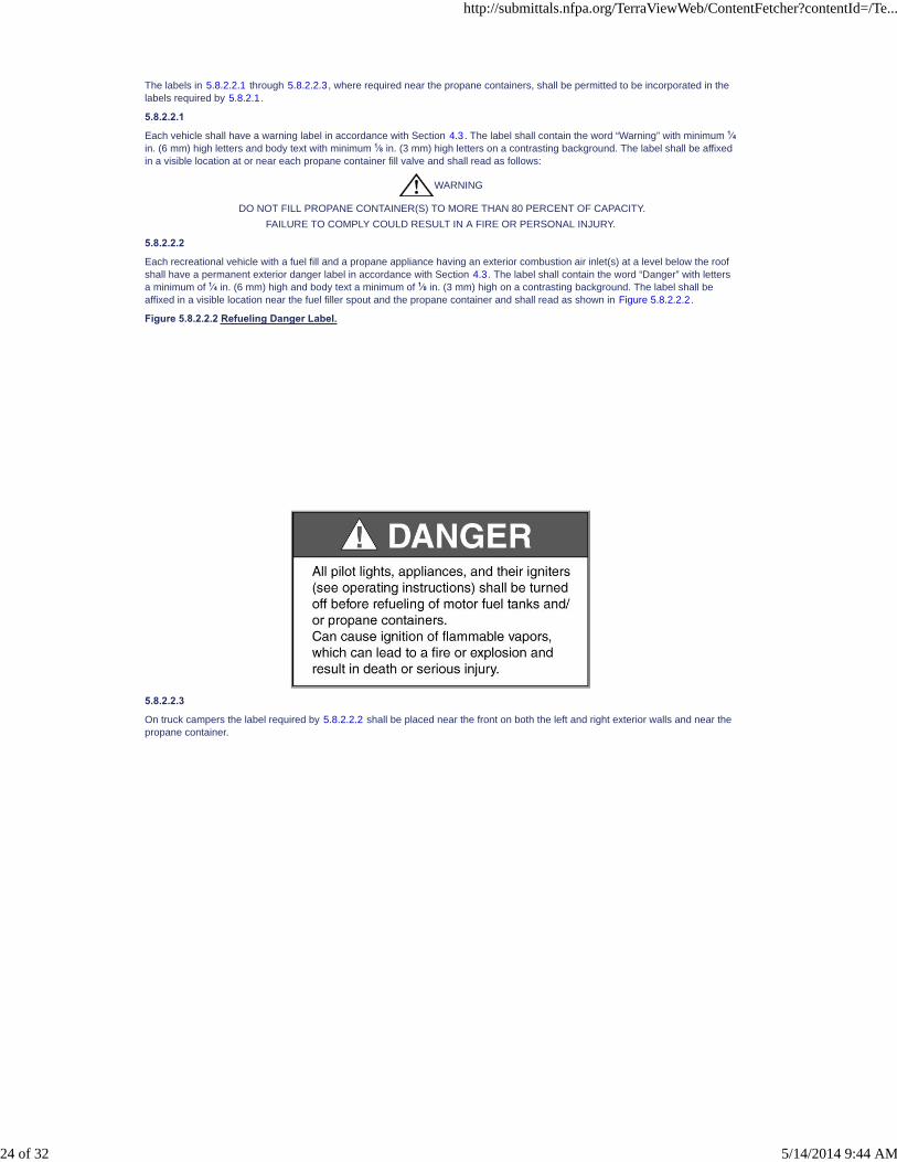
The labels in 5.8.2.2.1 through 5.8.2.2.3, where required near the propane containers, shall be permitted to be incorporated in thelabels required by 5.8.2.1.
5.8.2.2.1
Each vehicle shall have a warning label in accordance with Section 4.3. The label shall contain the word “Warning” with minimum 1⁄4in. (6 mm) high letters and body text with minimum 1⁄8 in. (3 mm) high letters on a contrasting background. The label shall be affixedin a visible location at or near each propane container fill valve and shall read as follows:
WARNING
DO NOT FILL PROPANE CONTAINER(S) TO MORE THAN 80 PERCENT OF CAPACITY.
FAILURE TO COMPLY COULD RESULT IN A FIRE OR PERSONAL INJURY.
5.8.2.2.2
Each recreational vehicle with a fuel fill and a propane appliance having an exterior combustion air inlet(s) at a level below the roofshall have a permanent exterior danger label in accordance with Section 4.3. The label shall contain the word “Danger” with lettersa minimum of 1⁄4 in. (6 mm) high and body text a minimum of 1⁄8 in. (3 mm) high on a contrasting background. The label shall beaffixed in a visible location near the fuel filler spout and the propane container and shall read as shown in Figure 5.8.2.2.2.
Figure 5.8.2.2.2 Refueling Danger Label.
5.8.2.2.3
On truck campers the label required by 5.8.2.2.2 shall be placed near the front on both the left and right exterior walls and near thepropane container.
http://submittals.nfpa.org/TerraViewWeb/ContentFetcher?contentId=/Te...
24 of 32 5/14/2014 9:44 AM

5.8.2.3
When fuel-burning equipment is installed by the recreational vehicle manufacturer, a permanent danger label with the word“Danger” with letters a minimum of 1⁄4 in. (6 mm) high and body text a minimum of 1⁄8 in. (3 mm) high letters on a contrastingbackground shall be affixed in a visible location near the range. This label, which shall be permitted to be affixed to the back of acabinet door providing the door is frequently used, shall read as shown in Figure 5.8.2.3
Figure 5.8.2.3 Propane Danger Label.
http://submittals.nfpa.org/TerraViewWeb/ContentFetcher?contentId=/Te...
25 of 32 5/14/2014 9:44 AM

PCs [1] SR-7 Hide Legislative
5.8.2.4
A permanent warning label with the word words “Warning” and “Danger” with letters a minimum of 1⁄4 in. (6 mm) high and body texta minimum of1⁄8 in. (3 mm) high on a contrasting background shall be affixed in a visible location adjacent to fuel-burning ranges andshall read as shown in Figure 5.8.2.4.
Figure 5.8.2.4 Fresh Air Danger/Warning Label.
5.9 Gasoline or Diesel Fuel Systems.
5.9.1 General.
The requirement of this section shall apply to the installation of gasoline or diesel fuel systems for nonprimary mover engineapplications in recreational vehicles.
5.9.2 Fuel Tank Construction.
Fuel tanks shall comply with the information requirements of 5.9.2.1 and 5.9.2.2.
http://submittals.nfpa.org/TerraViewWeb/ContentFetcher?contentId=/Te...
26 of 32 5/14/2014 9:44 AM
5.9.2.1
The tank shall be permanently and legibly marked in minimum 1⁄16 in. (1.6 mm) high letters by the tank manufacturer, with thefollowing minimum information:
(1) Name (logo) and address of manufacturer
(2) The month and year of manufacture
(3) Maximum level of fuel in U.S. gallons and liters
(4) Model identifier
(5) Statement of fuel suitability
5.9.2.2
The tank shall be identified by its manufacturer as being compliant with applicable sections of 5.9.5.
5.9.3
Fuel tanks shall be constructed in accordance with 5.9.3.1 through 5.9.3.7.
5.9.3.1 Construction of Metal Liquid Fuel Tanks — Joints.
Joints of a metal liquid fuel tank body shall be closed by arc-, gas-, seam-, or spot-welding, by brazing, by silver soldering, or bytechniques that provide heat resistance and mechanical securement at least equal to those specifically named. Joints shall not beclosed solely by crimping or by soldering with a lead-based or other soft solder.
5.9.3.2 Fittings.
The fuel tank body shall have flanges or spuds suitable for the installation of all fittings.
5.9.3.2.1
Fittings for withdrawing fuel from the fuel tank shall be located above the normal level of the fuel in the tank when the tank is full.
5.9.3.2.2
Drains and bottom fittings shall not be permitted.
5.9.3.3 Threads.
The threads of all fittings shall be Dryseal American Standard Taper Pipe Thread, specified in SAE J476 and the SAE Handbook,except that straight (nontapered) threads are permitted to be used on fittings that have integral flanges and use gaskets for sealing.At least four full threads shall be in engagement in each fitting.
5.9.3.4 Safety Venting System.
A metallic liquid fuel tank shall have a venting system that, in the event the tank is subjected to fire, prevents internal tank pressurefrom rupturing the tank's body or seams.
5.9.3.5 Rollover Vent.
Rollover vent valves identified as complying with 49 CFR 393.67(c)(10) shall be used, as applicable.
5.9.3.6 Pressure Resistance.
The body and fittings of a metallic liquid fuel tank, including the external filler assembly, shall be capable of withstanding an internalhydrostatic gauge pressure =10 psi (0.69 bar).
5.9.3.7 Overfill Restriction.
A liquid fuel tank shall be designed and constructed as follows:
(1) The tank shall not be filled with a quantity of fuel that exceeds 90 percent of the tank's liquid capacity.
(2) When the tank is filled, expansion of the fuel shall not cause fuel spillage.
5.9.4 Fill System.
5.9.4.1
The filler cap end shall be completely above the top of the fuel tank. Filler openings shall be located in accordance with 5.5.3.
5.9.4.2
Fuel filler openings into fuel tanks located below the normal level of fuel in the tank shall be equipped with an anti-expulsion valve orcheck valve installed at the fuel filler opening into the fuel tank.
5.9.5 Liquid Fuel Tank Tests.
5.9.5.1
Liquid fuel tanks shall be capable of passing the following leakage test:
(1) Procedure. Fill the tank to capacity with fuel having a temperature between 50°F (10°C) and 80°F (27°C). With the fillerpipecap installed, turn the tank through an angle of 150 degrees in any direction about any axis from its normal position.
(2) Required Performance. Neither the tank nor any fitting shall leak more than a total of 1 oz (28 g) by weight of fuel per minute inany position the tank assumes during the test.
5.9.5.2
Liquid fuel tanks shall be capable of passing the following drop test:
(1) Procedure. Fill the tank with a quantity of water having a weight equal to the weight of the maximum fuel load of the tank, thendrop the tank 30 ft (9.14 m) onto an unyielding surface so that it lands squarely on one corner.
(2) Required Performance. Neither the tank nor any fitting shall leak more than a total of 1 oz (28 g) by weight of water per minute.
http://submittals.nfpa.org/TerraViewWeb/ContentFetcher?contentId=/Te...
27 of 32 5/14/2014 9:44 AM

5.9.5.3
Each liquid fuel tank manufactured shall pass the following static pressure test:
(1) Procedure. Pressurize the tank with air or inert gas to a gauge pressure of 3 psi (21 kPa) and maintain for a period of at least 5minutes.
(2) Required Performance. During the 5-minute test period, a drop in pressure shall not occur.
5.9.5.4
Metallic liquid fuel tanks shall be capable of passing the following safety venting system test:
(1) Procedure. Fill the tank three fourths full with fuel, seal the fuel feed outlet, and invert the tank 2 ft (0.6 m) above the top edgeof a pan large enough to extend beyond the tank on all sides in plain view and deep enough to hold the entire fuel contents ofthe tank. When the fuel temperature is between 50°F (10°C) and 80°F (27°C), apply an enveloping flame to the tank so thatthe temperature of the fuel rises at a rate of not less than 6°F (3.3°C) per minute for the duration of the test. Remove theenveloping flame when the fuel system becomes self-heating (fuel venting from tank is ignited and acts as fuel for the fire),provided the temperature of the fuel continues to rise at a rate of not less than 6°F (3.3°C) per minute. Continue the test untilthe fuel tank is empty or until no further pressure rise is possible in the tank.
(2) Required Performance. The safety venting system required by 5.9.3.4 shall prevent the internal pressure in the tank fromexceeding a gauge pressure of 30 psi (207 kPa), and the body or seams of the tank shall not rupture during the test.
5.9.5.5
Side-mounted liquid fuel tanks shall be capable of passing the following filler pipe test:
(1) Procedure. Fill the tank with a quantity of water having a weight equal to the weight of the maximum fuel load of the tank, thendrop the tank 10 ft (3.05 m) onto an unyielding surface so that it lands squarely on its filler pipe.
(2) Required Performance. Neither the tank nor any fitting shall leak more than a total of 1 oz (28 g) by weight of water per minute.
5.9.6 Fuel Tank Installation.
5.9.6.1
The fuel tank shall be located under the floor, in a compartment, on a trailer A-frame, or forward of the front bulkhead below theoverhang of a fifth-wheel trailer.
5.9.6.2
The fuel tank and any of its attachments and fittings shall be located above rear and front clearance lines and thus shall beconsidered protected from road impact damage.
5.9.6.3
All measurements shall be determined from the bottom of the fuel tank or from the lowest fitting, support, or attachment on the fueltank or fuel tank housing, whichever is lower, while the vehicle is level and loaded to its maximum gross vehicle weight rating(GVWR).
5.9.6.4
The installation shall comply with 5.9.6.4.1 through 5.9.6.4.3.
5.9.6.4.1
The fuel tank shall be permitted to be located on a trailer A-frame if no part extends below the bottom of the A-frame members.
5.9.6.4.2
Where the fuel tank is located between the chassis main rails, the rear point shall be permitted to be taken at the bottom of the mainrail. Skid bars shall not be used to lower this point.
5.9.6.4.3
The fuel tank shall be permitted to be located in a compartment under the following conditions:
(1) A compartment containing a fuel tank with filler opening, vent, or any combination thereof within the compartment shall haveno floor.
(2) A compartment containing a fuel tank that is filled and vented to the exterior shall be permitted to have a floor, provided thatthe compartment sidewalls and floor are resistant and nonabsorbent to fuel, that the floor has a minimum 1⁄2 in. (13 mm)diameter drainage hole to the exterior at each low point, and that the joints between compartment sidewalls and floor aresealed to prevent fuel entry.
(3) The fuel tank compartment shall be vapor resistant to the recreational vehicle interior and sealed so that vapors cannot travelinto the interior of the vehicle. Sealing compounds used to seal the compartment shall be fuel resistant.
(4) The fuel tank compartment shall not contain flame- or spark-producing equipment.
5.9.6.5
The fuel tank shall be secured by fastenings that hold it in place when a force equal to eight times the fuel tank's filled weight isapplied through the filled fuel tank's center of gravity in any direction.
5.9.6.6
Metallic fuel tanks shall be electrically bonded to the vehicle chassis.
5.9.6.7
Fuel tanks shall be securely installed in such locations as to be removable for service, repair, or replacement without the necessityof removing permanent structural members.
5.9.6.8
Side-fill fuel tanks installed between the vehicle's main rails shall be permitted to have the fuel tank filler openings located below thenormal level of fuel in the tank and shall comply with 5.9.4.
http://submittals.nfpa.org/TerraViewWeb/ContentFetcher?contentId=/Te...
28 of 32 5/14/2014 9:44 AM
5.9.7 Filler Pipe.
5.9.7.1
The filler pipe and vent of a fuel tank shall permit filling the tank with fuel at a rate of at least 12 gpm (45.4 L/m) without fuel spillage.
5.9.7.2
Each filler pipe shall be fitted with a cap that can be fastened securely over the opening in the filler pipe. Screw threads and abayonet-type joint are methods of conforming to the requirements of this 5.9.7.
5.9.7.3
Sealing compounds used around the filler pipe and in the area described in 5.9.7.6 shall be fuel resistant.
5.9.7.4*
The type of fuel to be used shall be identified on or adjacent to the filler cap.
5.9.7.5
The area surrounding fuel filler pipes and vents shall be sealed so that vapors cannot travel between the exterior and interiorsurfaces of the recreational vehicle.
5.9.7.6
The sidewall surface below the filler cap and extending at least 12 in. (305 mm) to each side of the cap's vertical centerline shall beconstructed of fuel-resistant nonabsorbent materials.
5.9.7.7
Metallic fuel fillers shall be electrically bonded to the vehicle chassis.
5.9.8 Fuel Distribution System.
5.9.8.1 Location.
Each fuel system shall be located on the vehicle so that the following apply:
(1) No part of the system shall extend beyond the widest part of the vehicle.
(2) Fuel spilled vertically from a fuel tank while it is being filled shall not contact any part of the exhaust or electrical systems of thevehicle, except the fuel level indicator assembly.
(3) A fuel line shall not extend between a towed vehicle and the vehicle that is towing it while the vehicles are in motion.
(4) A fuel system shall not supply fuel by gravity or siphon feed directly to the carburetor or injector.
5.9.8.2
The entire fuel system shall be liquidtight and vapor resistant to the interior of the vehicle.
5.9.8.3
Valves, filters, strainers, and similar components shall be accessible for maintenance.
5.9.8.4
Equipment located above the clearance lines or as specified in 5.9.6.4.1 shall be considered protected.
5.9.8.5
Tubing shall be constructed of prime aluminized steel or material approved for use with fuel.
5.9.8.6
Hose shall conform at a minimum to SAE J30 R7 or the equivalent.
5.9.8.7
Hose-to-tube joints shall remain leak free when subjected to a 20 lb (9.0 kg) axial pull test applied for 1 minute.
5.9.8.8
The fuel distribution system shall be secured and supported in place to minimize chafing.
5.9.8.9
Rigid fuel distribution system piping or hose shall be secured and supported at intervals of not more than 4 ft (1.2 m).
5.9.8.10
The fuel distribution system shall maintain at least a 41⁄2 in. (114 mm) clearance from any unshielded exhaust system components.
5.9.8.11
The fuel system shall not be in contact with electrical wiring except as required for component operation.
5.9.8.12
The fuel system shall be designed so that leakage from fuel tanks or joints does not contact electrical or exhaust systemcomponents.
5.9.8.13
Drain troughs shall be permitted to be used as required.
5.9.8.14
Fittings and piping (tubing, hose, and pipe) in the fuel distribution system shall not be located inside any floor, wall, partition, or otherconcealed construction space.
http://submittals.nfpa.org/TerraViewWeb/ContentFetcher?contentId=/Te...
29 of 32 5/14/2014 9:44 AM

5.9.8.15
Clamps shall be in accordance with the following:
(1) Clamps shall have a nonperforated band and meet the specifications of SAE J1508.
(2) Clamps shall be identified for the type and size of the fuel lines used.
5.9.9 Fuel-Dispensing Systems.
5.9.9.1
Systems for dispensing fuel to other vehicles or containers shall be permitted when constructed in accordance with 5.9.8 and otherstate and federal laws or regulations as applicable.
5.9.9.2
All fuel-dispensing systems shall have an emergency manual shutoff valve or remotely controlled electronic shutoff valve that isreadily accessible during fuel dispensing and that is located within the hose storage compartment or on the vehicle's exterior withinthe length of the fully extended hose nozzle and not more than 18 in. (457 mm) from the vehicle's outside wall.
5.9.9.3
A label with a minimum 1⁄4 in. (6 mm) high red block letters on a contrasting background and made of material that does notdeteriorate when in contact with petroleum-based products shall be placed adjacent to the shutoff valve or valve control and read asfollows:
FUEL DISPENSING SYSTEM
EMERGENCY SHUTOFF SWITCH
5.9.9.4
All fuel-dispensing equipment, including but not limited to tanks, pumps, hoses, and valves, shall be protected from road impactdamage.
5.9.9.5
Equipment located above the clearance lines or as specified in 5.9.6.4.1 shall be considered protected.
5.9.9.6
All fuel-dispensing equipment shall be accessible only from the exterior of the vehicle.
5.9.10 Fuel-Dispensing Compartments and Enclosures.
5.9.10.1
Compartments and enclosures that house dispensing systems shall be made of nonporous and noncombustible material, sealedfrom the interior atmosphere of the recreational vehicle and vented.
5.9.10.2
These compartments shall be ventilated with openings having a minimum area of 1.7 in.2 (1100 mm2) within 2 in. (51 mm) of boththe top and the bottom.
5.9.10.3
These compartments shall have a minimum 1⁄2 in. (13 mm) diameter drainage hole to the exterior at each low point.
5.9.10.4
These compartments shall not contain flame- or spark-producing equipment.
5.9.11 Other Fuel-Dispensing System Requirements.
5.9.11.1
Fuel tanks with dispensing capabilities shall be provided with a method of venting while fuel is being dispensed.
5.9.11.2
Nozzles shall be used for the dispensing of fuel and shall be listed to ANSI/UL 842, designed for use with unleaded fuel, of atrigger-and-handle type, and made with a nonferrous body.
5.9.11.3
A fuel-dispensing system shall have provisions to prevent unauthorized use.
5.9.11.4
The fuel-dispensing system shall be designed and installed to prevent fuel from siphoning due to hose failure.
5.9.11.5
The fuel-dispensing hose between the nozzle and its first connection on the vehicle shall be a hose assembly listed to ANSI/UL330.
5.9.11.6
Fuel-dispensing hoses shall be limited in length to a maximum of 5 ft (1.5 m) from the side of the recreational vehicle.
5.9.11.7
Tanks and valves used in fuel dispensing systems shall be identified for use with fuel being dispensed.
5.9.11.8
Pumps used in fuel dispensing systems shall be identified for the fuel being dispensed, and the pump motor shall be listed.
5.9.11.9
Nonsubmersible fuel pumps shall be securely attached to the vehicle.
http://submittals.nfpa.org/TerraViewWeb/ContentFetcher?contentId=/Te...
30 of 32 5/14/2014 9:44 AM
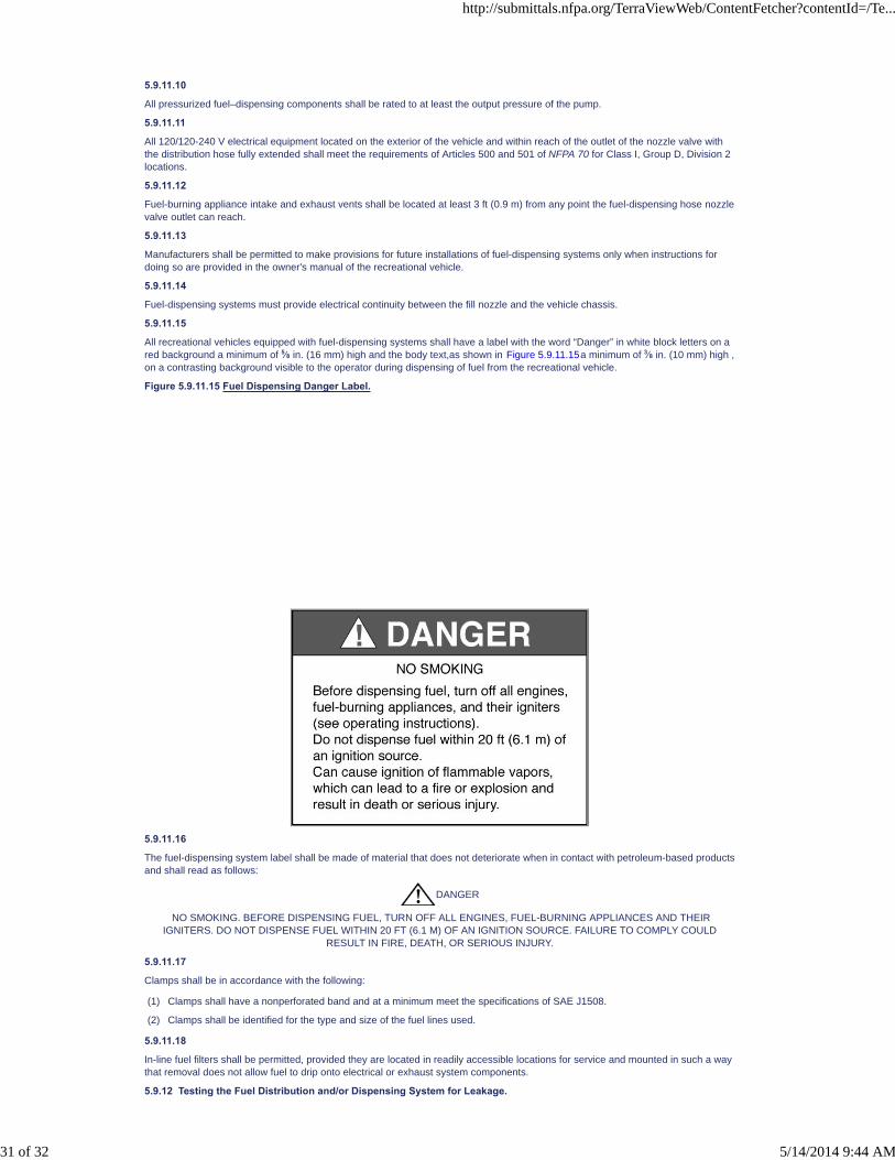
5.9.11.10
All pressurized fuel–dispensing components shall be rated to at least the output pressure of the pump.
5.9.11.11
All 120/120-240 V electrical equipment located on the exterior of the vehicle and within reach of the outlet of the nozzle valve withthe distribution hose fully extended shall meet the requirements of Articles 500 and 501 of NFPA 70 for Class I, Group D, Division 2locations.
5.9.11.12
Fuel-burning appliance intake and exhaust vents shall be located at least 3 ft (0.9 m) from any point the fuel-dispensing hose nozzlevalve outlet can reach.
5.9.11.13
Manufacturers shall be permitted to make provisions for future installations of fuel-dispensing systems only when instructions fordoing so are provided in the owner's manual of the recreational vehicle.
5.9.11.14
Fuel-dispensing systems must provide electrical continuity between the fill nozzle and the vehicle chassis.
5.9.11.15
All recreational vehicles equipped with fuel-dispensing systems shall have a label with the word “Danger” in white block letters on ared background a minimum of 5⁄8 in. (16 mm) high and the body text,as shown in Figure 5.9.11.15a minimum of 3⁄8 in. (10 mm) high ,on a contrasting background visible to the operator during dispensing of fuel from the recreational vehicle.
Figure 5.9.11.15 Fuel Dispensing Danger Label.
5.9.11.16
The fuel-dispensing system label shall be made of material that does not deteriorate when in contact with petroleum-based productsand shall read as follows:
DANGER
NO SMOKING. BEFORE DISPENSING FUEL, TURN OFF ALL ENGINES, FUEL-BURNING APPLIANCES AND THEIRIGNITERS. DO NOT DISPENSE FUEL WITHIN 20 FT (6.1 M) OF AN IGNITION SOURCE. FAILURE TO COMPLY COULD
RESULT IN FIRE, DEATH, OR SERIOUS INJURY.
5.9.11.17
Clamps shall be in accordance with the following:
(1) Clamps shall have a nonperforated band and at a minimum meet the specifications of SAE J1508.
(2) Clamps shall be identified for the type and size of the fuel lines used.
5.9.11.18
In-line fuel filters shall be permitted, provided they are located in readily accessible locations for service and mounted in such a waythat removal does not allow fuel to drip onto electrical or exhaust system components.
5.9.12 Testing the Fuel Distribution and/or Dispensing System for Leakage.
http://submittals.nfpa.org/TerraViewWeb/ContentFetcher?contentId=/Te...
31 of 32 5/14/2014 9:44 AM

5.9.12.1
The fuel system shall be proven by test to be leak free by maintaining a minimum air pressure of 1psi (6.9 kPa) for at least 10minutes.
5.9.12.2
The fuel filler hose or pipe's connection to the tank shall not be required to meet the pressure test of 5.9.12.1.
5.9.12.3
Before the test is begun, the temperature of the air and of the piping shall be approximately the same, and a uniform temperatureshall be maintained throughout the test period.
5.9.12.4
Leaks, if observed, shall be located and corrected.
5.9.12.5
Defective material shall be replaced.
5.9.12.6
Products that contain ammonia or chlorine shall not be used for locating leaks.
5.9.12.7
The test shall be conducted by either of the following methods:
(1) Air pressure as follows:
(a) The fuel system shall be pressurized per 5.9.12.1.
(b) The source of air pressure to the fuel distribution system shall be shut off.
(c) The pressure in the system shall be measured over a period of 10 minutes with a manometer or other pressure-sensingdevice designed and calibrated to measure in increments of not greater than 1⁄10 psi (.69 kPa).
(d) During the 10-minute test period, a drop in pressure shall not occur.
(2) Bubble type leak detector as follows:
(a) A bubble-type leak detector shall be installed between the source of pressure and the fuel distribution system.
(b) The bubble detector shall not indicate any air flow for a period of 1 minute.
5.9.13 Future Generator Installations.
Where a fuel system is installed for an electric generator but the electric generator is not installed at the recreational vehicle factory,all fuel lines between the fuel tank and the generator compartment shall be routed and plugged at the open end(s).
5.10 Propane Vehicle Propulsion Engine Installations.
5.10.1
Propane systems supplying both vapor and liquid withdrawal shall comply with Section 11.3 of NFPA 58, except as provided for in5.10.2.
5.10.2
Tanks shall be mounted in accordance with 5.2.3.3 and secured in accordance with 5.2.4.
5.11 Fuel Cells and Fuel Cell Systems.
5.11.1
Fuel cells and fuel cell systems shall be listed for installation in recreational vehicles.
5.11.2
Fuel cells and fuel cell systems shall be installed in accordance with the terms of their listing and according to the manufacturer’sinstallation instructions.
5.11.3
Fuel cell installation shall be vapor resistant to the vehicle interior.
5.11.4
Fuel cells shall be accessible for inspection, service, repair, or replacement.
5.11.5
A fuel cell system shall be securely attached to the vehicle.
http://submittals.nfpa.org/TerraViewWeb/ContentFetcher?contentId=/Te...
32 of 32 5/14/2014 9:44 AM

NFPA 1192®, Standard on Recreational Vehicles, 2011 Edition
NFPA STANDARDS DEVELOPMENT SITESECOND DRAFT REPORTClosing Date: July 19, 2013 NOTE: All Public Comment must be received by 5:00 pm EST/EDST on the published Closing Date.
Quick Print
PCs [1]
PCs [1]
PCs [2] SR-8 Hide Legislative
PCs [2] SR-8 Hide Legislative
Chapter 6 Fire and Life Safety Provisions
6.1 Interior Finish and Textile or Film Materials.
6.1.1 Interior Finish Flame Spread Limitation.
6.1.1.1
Interior finish (as defined in 3.3.34) of walls, partitions, ceilings, exterior passage doors, cabinets, habitable areas, hallways, andbath or toilet rooms, including tub/shower walls, of recreational vehicles shall be of materials with a flame spread index that doesnot exceed 200 when tested in accordance with ASTM E84 or ANSI/UL 723.
6.1.1.2
Cabinet door and drawer faces, exposed cabinet bottoms and end panels, and tub/shower walls shall be permitted to obtain aradiant panel index of the same value as determined in accordance with ASTM E 162.
6.1.1.3
The flame spread limitations shall not apply to moldings; trim; furnishings; windows, door, or skylight frames and casings; interiorpassage doors; countertops; cabinet rails; stiles; mullions; toe kicks; and padded cabinet ends.
6.1.2 Combustibility of Textile or Film Materials.
Where the walls, partitions, or ceilings consist of textile or film materials, such as tent fabric, insect screening, and flexible plasticweather protection, they shall conform to the requirements of 49 CFR 571.302, paragraphs S4.3 and S5 of Federal Motor VehicleSafety Standard No. 302, “Flammability of Interior Materials.”
6.1.3 Use of Cellular Foam or Foamed Plastic Materials.
Cellular foam or foamed plastic materials shall not be used for interior finish (as defined in 3.3.34) in recreational vehicles.
Exception No. 1: Cellular or foamed plastic materials shall be permitted on the basis of fire tests that substantiate theircombustibility characteristics, for the use intended, in actual fire conditions.
Exception No. 2: Incidental use of cellular or foamed materials for molding, trim, splash panels, and on doors shall be permitted.
6.1.4 Glazing Materials.
All interior glazing materials with an exposed area exceeding 431 in.2 (278,064 mm2) shall comply with ANSI Z97.1 GlazingMaterials Used in Buildings, Safety Performance Specifications and Methods of Test; 16 CFR 1201, “Safety Standard forArchitectural Glazing Materials”; or equal requirements and shall be so identified by the manufacturer of the glazing material.
6.2 Recreational Vehicle Means of Escape.
6.2.1 Minimum Means of Escape.
6.2.1.1
Each living and sleeping area in a recreational vehicle shall have one primary means of escape and at least one secondary meansof escape.
6.2.1.2
A secondary means of escape shall not be required where the sleeping area or living area has a door Each sleeping area shallhave two different paths to escape to the outside of the recreational vehicle.
6.2.1.2.1
Where more than one sleeping area is provided and a sleeping area has a door as a primary means of escape to the outside ofthe recreational vehicle, no additional escape shall be required for this area.
6.2.1.3
The primary means of escape shall be a door to the outside of the recreational vehicle.
6.2.1.4
The path to an escape in the set-up and travel mode shall have a minimum of 13 inches (330mm) of clear width for the entire lengthof the path.
6.2.1.5
http://submittals.nfpa.org/TerraViewWeb/ContentFetcher?contentId=/Te...
1 of 8 5/14/2014 9:44 AM

A recreational vehicle with collapsible, nonrigid roof or side wall sections that is incapable of having a secondary means of escapewhile in the travel mode shall have a warning label , with the word “WARNING” with letters a minimum of ¾ in. (19 mm) high andbody text a minimum 1/4 in. (6 mm) high, on a contrasting background, affixed in a visible location on the interior of the primarymeans of escape and read as shown in Figure 6.2.1.5.
Figure 6.2.1.5 Means of Escape Warning Label.
6.2.1.5.1
The owner’s manual shall contain, as a minimum, this statement:
The following label has been placed on the interior of the main entry door and reads as follows:
Do not utilize this RV unless fully set up because a secondary means of escape is not available. May result in death or seriousinjury.
6.2.1.6
The requirements of 6.2.1.5 shall not apply to folding camping trailers.
6.2.2 Secondary Means of Escape.
6.2.2.1
The secondary means of escape shall be as follows:
(1) An outside window, outside door, or roof hatch
(2) Operable in accordance with 6.2.4
(3) Sized in accordance with 6.2.5
(4) Independent of and remote from the primary means of escape
6.2.2.2
At least one secondary means of escape shall be located on an exterior wall other than the primary means of escape or shall belocated in the roof.
6.2.2.3
The bottom of any secondary means of escape shall be 36 in. (914 mm) or less above either the vehicle floor or a readily accessiblehorizontal surface capable of supporting a mass of 300 lb (136 kg).
6.2.2.4
The driver’s door of a motorhome shall be permitted as a secondary means of escape.
6.2.2.5
When a secondary means of escape is located in the roof of the vehicle, a ladder or equivalent means for descending from the roofshall be provided.
6.2.3 Marking of Secondary Means of Escape.
6.2.3.1
The secondary means of escape, other than exterior doors, shall be identified by a permanent label with the word “EXIT” in redletters of 1 in. (25 mm) minimum height on a contrasting background.
6.2.3.2
“EXIT” labels shall be located on or within 8 in. (203 mm) of the secondary means of escape.
6.2.3.3
All handles that must be operated to open a secondary means of escape, except for exterior and interior doors, shall be red in color.
6.2.4 Operation of Means of Escape.
6.2.4.1
The latch mechanism of any means of escape shall be operable by hand and shall not require the use of a key or special tool foroperation from inside the vehicle.
http://submittals.nfpa.org/TerraViewWeb/ContentFetcher?contentId=/Te...
2 of 8 5/14/2014 9:44 AM

6.2.4.2
No more than 20 lb of force (89 N) shall be required to open a means of escape.
6.2.5 Size of Means of Escape.
6.2.5.1*
Means of escape, if not an exterior passage door, shall provide an opening of sufficient size to permit the unobstructed passage,with its major axis parallel to the plane of the opening and horizontal at all times, of an ellipsoid generated by rotating about theminor axis an ellipse having a major axis of 24 in. (610 mm) and a minor axis of 17 in. (432 mm).
6.2.5.2
An exterior passage door, if used for a means of escape, shall provide an unobstructed opening with a minimum horizontaldimension of 18 in. (432 mm) and a minimum vertical dimension of 48 in. (1219 mm).
6.3 Fire Detection Equipment.
6.3.1 Smoke Alarms.
6.3.1.1
At least one integral battery-operated smoke alarm shall be installed in each recreation vehicle.
6.3.1.2
A fifth-wheel trailer or travel trailer that has only interior lighting capable of being powered only by a 120 V or 120 V/240 V externalpower supply shall be permitted to be equipped with a 120 V operated smoke alarm with battery backup that shall be on a branchcircuit supplying lighting and receptacle outlets that shall not have ground-fault protection.
6.3.2* Smoke Alarm Listing Requirement.
The smoke alarm shall be listed and marked on the device as being suitable for installation in recreational vehicles under therequirements of ANSI/UL 217.
6.3.3 Installation of Smoke Alarm.
The required smoke alarm shall be installed in accordance with its listing but not within the separate sleeping areas.
6.3.4 Operational Check Warning Label.
A warning label with the word “Warning” a minimum of 1⁄4 in. (6 mm) high and body text a minimum of 1⁄8 in. (3 mm) high on acontrasting background shall be affixed in a visible location on or within 24 in. (610 mm) of the smoke alarm and shall read asshown in Figure 6.3.4.
Figure 6.3.4 Smoke Alarm Warning Label.
6.3.5 Owner’s Manual Information.
The owner’s manual shall contain a statement regarding smoke alarm expiration.
6.4 Other Considerations.
6.4.1 Provisions for Portable Fire Extinguishers.
6.4.1.1
Each motor home shall be equipped with a listed portable fire extinguisher with a minimum rating of 10-B:C.
6.4.1.2
Each recreational vehicle equipped with fuel-burning equipment (other than the prime mover engine) or a 120/240 V electricalsystem shall be provided with a listed portable fire extinguisher with a minimum rating of 5-B:C as defined in NFPA 10, Standard forPortable Fire Extinguishers, or CAN/ULC-S508, Standard for the Rating and Fire Testing of Fire Extinguishers..
6.4.1.3
The fire extinguisher shall be installed in accordance with its listing to ANSI/UL 299, Dry Chemical Fire Extinguishers, orCAN/ULC-S504, Standard for Dry Chemical Fire Extinguishersand to to NFPA 10, Standard for Portable Fire Extinguishers, orCAN/ULC-S508, Standard for the Rating and Fire Testing of Fire Extinguishers, and shall be located in the recreational vehicleinterior within 24 in. (610 mm) of the opening of the primary means of escape.
6.4.2 Liquid Fuel Filler Installation Provisions.
http://submittals.nfpa.org/TerraViewWeb/ContentFetcher?contentId=/Te...
3 of 8 5/14/2014 9:44 AM
6.4.2.1
The area surrounding liquid fuel filler pipes and vent tubing shall be sealed so that fuel vapors cannot travel into concealed spacesbetween exterior and interior surfaces of the recreational vehicle or to the interior of the vehicle.
6.4.2.2
Materials and sealants used to seal the fill pipe and vent tubing location shall be nonabsorbent and resistant to intermittent contact(splashing) with fuel.
6.4.3 Combustion Engine Exhausts and Vehicle Wall Openings.
6.4.3.1
The terminus of combustion exhausts shall extend beyond the periphery of the vehicle and discharge exhaust gases away from thevehicle. Diesel exhaust systems complying with EPA emissions regulations effective January 1, 2007, shall be permitted to have theterminus no more than 12 in. (305 mm) inside the periphery of the vehicle and shall discharge exhaust gases away from the vehicle.
6.4.3.2
The terminus of combustion exhausts other than the primary mover engine shall not be permitted within a vertical distance of 36 in.(914 mm) below any expandable portion of the recreational vehicle.
6.4.3.3
Combustion exhaust components installed by the recreational vehicle manufacturer shall not extend or protrude in a manner thatcould subject them to road damage.
6.4.3.4
Combustion exhaust shall not terminate so that a communicable air passage exists into the living area within an area defined by adistance of 6 in. (152 mm) measured from the tailpipe terminus perimeter as projected onto the vehicle side.
6.4.3.5
Vents or windows that can be opened for ventilation shall not be installed in the rear wall of motorhomes and truck campers.
6.4.3.6
Normally unopenable alternate exit windows shall be permitted in rear walls.
6.4.3.7
Rear entry doors with fixed windows shall be permitted in truck campers.
6.4.3.8
Rear entry doors with fixed windows shall be permitted in motorhomes, provided that no combustion exhausts discharge from therear of the vehicle.
6.4.4 Floor Penetrations for Recreational Vehicles Equipped with or Designed for Future Installation of an InternalCombustion Engine(s).
6.4.4.1
No uncovered hole(s) shall be permitted in or through the floor.
6.4.4.2
Holes or other penetrations provided or made for piping, wiring, or other similar components for systems addressed by this standardshall be filled or sealed.
6.4.5 Installation of Internal Combustion Engine Generators.
6.4.5.1
Internal combustion engine–driven generator units (subject to the provisions of this standard) shall be listed and installed inaccordance with the manufacturer's instructions and shall be vapor resistant to the interior of the vehicle.
6.4.5.2
Where a generator compartment is used to isolate the installed generator from the vehicle's interior, or a compartment is providedfor the future installation of a generator and is intended to isolate the future generator from the vehicle interior, the generatorcompartment shall be lined with galvanized steel not less than 26 MSG thick.
6.4.5.2.1
Seams and joints shall be lapped, mechanically secured, and made vapor resistant to the interior of the vehicle.
6.4.5.2.2
Alternative materials and methods of construction shall be permitted in accordance with Section 1.5.
6.4.5.2.3
Liquid fuel lines and exhaust systems shall not penetrate into the living area.
6.4.5.2.4
Holes into the living area shall be sealed.
6.4.6 Carbon Monoxide (CO) Alarms.
All recreational vehicles shall be equipped with a CO alarm listed and marked on the device as being suitable for use in recreationalvehicles under the requirements of ANSI/UL 2034 or CSA 6.19 and installed according to the terms of its listing.
6.4.7 Special Transportation Provisions.
6.4.7.1
All recreational vehicles providing any entrance door greater than 36 in. (914 mm) in width and an access ramp for that door or thatare promoted as providing the ability to transport and store internal combustion engine vehicles shall be constructed in accordancewith 6.4.7.2 through 6.4.7.12.
http://submittals.nfpa.org/TerraViewWeb/ContentFetcher?contentId=/Te...
4 of 8 5/14/2014 9:44 AM

PCs [1] SR-9 Hide Legislative
6.4.7.2
Venting shall be provided by openings, windows, or ram air ventilation systems.
6.4.7.3
Venting shall provide a minimum of 10 in.2 (6452 mm2) of openable area in the forward upper end of the transportation area and 10
in.2 (6452 mm2) of openable area in the lower rear end of the transportation area.
6.4.7.3.1
The lower rearward vent shall not be located in the floor of recreational vehicles either equipped with or designed for the futureinstallation of a combustion engine unless a permanent wall of separation (door and windows permitted) exists between thetransport area and the living area.
6.4.7.4
Flooring of the transportation area shall be in accordance with 6.4.7.4.1 and 6.4.7.4.2.
6.4.7.4.1
The flooring of the transportation area shall be nonabsorbent and resistant to intermittent contact with flammable liquids.
6.4.7.4.2
Where flooring in the transportation area contains a seam or meets a wall, these areas shall be sealed with sealant that isnonabsorbent and resistant to intermittent contact with flammable liquids.
6.4.7.5
An additional listed portable fire extinguisher with a minimum rating of 10-B:C, as defined in NFPA 10, Standard for Portable FireExtinguishers, , shall be provided in the cargo special transportation area within 24 in. (610 mm) of the exterior door that serves thecargo special transportation area. .
6.4.7.6
Propane ranges and ovens containing a pilot light shall be equipped with a pilot light shutoff.
http://submittals.nfpa.org/TerraViewWeb/ContentFetcher?contentId=/Te...
5 of 8 5/14/2014 9:44 AM

6.4.7.7
Recreational vehicles with an interior area designed for transporting internal combustion engine vehicles shall have a danger labelplaced inside the recreational vehicle adjacent to each entry and visible to anyone entering the recreational vehicle. The label(s)shall be printed , with the word “Danger” a minimum of 3⁄4 in. (19 mm) high, the body text that shall be a minimum of 1⁄4 in. (6 mm)high, and with the letters on a contrasting background, and shall read as shown in Figure 6.4.7.7.
Figure 6.4.7.7 Internal Combustion Engine Transporting Danger Label.
http://submittals.nfpa.org/TerraViewWeb/ContentFetcher?contentId=/Te...
6 of 8 5/14/2014 9:44 AM
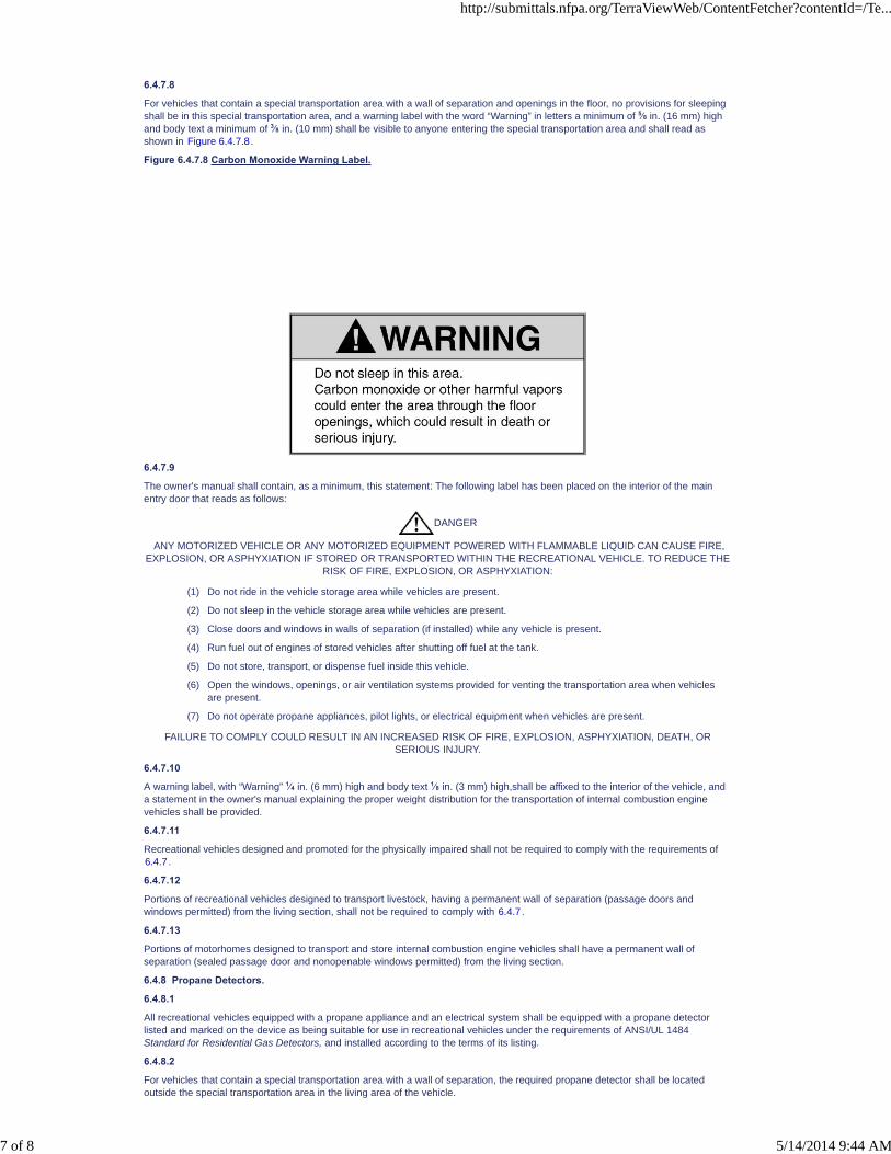
6.4.7.8
For vehicles that contain a special transportation area with a wall of separation and openings in the floor, no provisions for sleepingshall be in this special transportation area, and a warning label with the word “Warning” in letters a minimum of 5⁄8 in. (16 mm) highand body text a minimum of 3⁄8 in. (10 mm) shall be visible to anyone entering the special transportation area and shall read asshown in Figure 6.4.7.8.
Figure 6.4.7.8 Carbon Monoxide Warning Label.
6.4.7.9
The owner's manual shall contain, as a minimum, this statement: The following label has been placed on the interior of the mainentry door that reads as follows:
DANGER
ANY MOTORIZED VEHICLE OR ANY MOTORIZED EQUIPMENT POWERED WITH FLAMMABLE LIQUID CAN CAUSE FIRE,EXPLOSION, OR ASPHYXIATION IF STORED OR TRANSPORTED WITHIN THE RECREATIONAL VEHICLE. TO REDUCE THE
RISK OF FIRE, EXPLOSION, OR ASPHYXIATION:
(1) Do not ride in the vehicle storage area while vehicles are present.
(2) Do not sleep in the vehicle storage area while vehicles are present.
(3) Close doors and windows in walls of separation (if installed) while any vehicle is present.
(4) Run fuel out of engines of stored vehicles after shutting off fuel at the tank.
(5) Do not store, transport, or dispense fuel inside this vehicle.
(6) Open the windows, openings, or air ventilation systems provided for venting the transportation area when vehiclesare present.
(7) Do not operate propane appliances, pilot lights, or electrical equipment when vehicles are present.
FAILURE TO COMPLY COULD RESULT IN AN INCREASED RISK OF FIRE, EXPLOSION, ASPHYXIATION, DEATH, ORSERIOUS INJURY.
6.4.7.10
A warning label, with “Warning” 1⁄4 in. (6 mm) high and body text 1⁄8 in. (3 mm) high,shall be affixed to the interior of the vehicle, anda statement in the owner's manual explaining the proper weight distribution for the transportation of internal combustion enginevehicles shall be provided.
6.4.7.11
Recreational vehicles designed and promoted for the physically impaired shall not be required to comply with the requirements of6.4.7.
6.4.7.12
Portions of recreational vehicles designed to transport livestock, having a permanent wall of separation (passage doors andwindows permitted) from the living section, shall not be required to comply with 6.4.7.
6.4.7.13
Portions of motorhomes designed to transport and store internal combustion engine vehicles shall have a permanent wall ofseparation (sealed passage door and nonopenable windows permitted) from the living section.
6.4.8 Propane Detectors.
6.4.8.1
All recreational vehicles equipped with a propane appliance and an electrical system shall be equipped with a propane detectorlisted and marked on the device as being suitable for use in recreational vehicles under the requirements of ANSI/UL 1484Standard for Residential Gas Detectors, and installed according to the terms of its listing.
6.4.8.2
For vehicles that contain a special transportation area with a wall of separation, the required propane detector shall be locatedoutside the special transportation area in the living area of the vehicle.
http://submittals.nfpa.org/TerraViewWeb/ContentFetcher?contentId=/Te...
7 of 8 5/14/2014 9:44 AM

PCs [2] SR-10 Hide Legislative
SR-10 Hide Legislative
6.4.9 Protruding Component Operation.
Any protruding component that is operated The operation of protruding components (i.e., awning, landing gear, level system orslide outs) controlled by means of an electrical switch or controller accessible for operation when , shall be incapable of activationwhile the vehicle is in transit, shall comply with the following: .
Be provided with momentary switching with nonlatching circuitry or the equivalent
Not be capable of activation while the vehicle is in motion
6.4.10 Slide-Out Room Activation.
Slide-out room activation shall use only momentary switching with non-latching circuitry or equivalent.
6.4.11 Power Bed Activation.
Power bed activation shall use only momentary switching with non-latching circuitry or equivalent.
6.5 Automatic Generator Starting System (AGS) Requirements.
6.5.1
A manual command shall be required to activate the AGS.
6.5.2
Manually stopping the engine generator shall turn off the AGS.
http://submittals.nfpa.org/TerraViewWeb/ContentFetcher?contentId=/Te...
8 of 8 5/14/2014 9:44 AM

NFPA 1192®, Standard on Recreational Vehicles, 2011 Edition
NFPA STANDARDS DEVELOPMENT SITESECOND DRAFT REPORTClosing Date: July 19, 2013 NOTE: All Public Comment must be received by 5:00 pm EST/EDST on the published Closing Date.
Quick PrintChapter 7 Plumbing Systems
7.1 Plumbing System.
7.1.1 General Requirements.
7.1.1.1
Any plumbing system installed in a recreational vehicle shall conform to the provisions of this standard.
7.1.1.2
Requirements for any size, weight, or quality of material modified by the terms minimum, not less than, at least, and similarexpressions shall be minimum standards.
7.1.1.3
All plumbing fixtures, drains, appurtenances, and appliances designed or used to receive or discharge liquid waste or body wasteshall be connected to the recreational vehicle drainage system in a manner provided by this standard.
7.1.2 Components.
7.1.2.1
Plumbing materials, devices, fixtures, fittings, equipment, appliances, accessories, and appurtenances installed in or attached to arecreational vehicle shall be listed and conform to minimum performance and sanitation standards as applicable or shall bespecifically approved by the authority having jurisdiction when listing by an approved listing agency is not available.
7.1.2.2
All listed components shall be installed in accordance with terms of their listing.
7.1.2.3
All design, construction, and workmanship shall be in conformance with accepted engineering practices.
7.1.2.4
All valves, pipes, and fittings shall be installed in correct relationship to the direction of flow.
7.1.2.5
Plastic, brass, or combination plastic and brass valves shall be listed. This requirement shall not become effective until September1, 2017, for brass or combination plastic and brass valves.
7.1.3 Assembling of Pipe.
7.1.3.1
All joints and connections shall be correctly assembled for tightness.
7.1.3.2
Pipe threads shall be fully engaged with the threads of the fittings.
7.1.3.3
Pipe threads and slip joints shall not be wrapped with string, paper, putty, or similar fillers.
7.1.3.4
Plastic pipe and copper tubing shall be inserted to the full depth of the fitting sockets.
7.1.3.5
Sealants used on threaded pipe or fittings shall be identified for use with potable water.
7.1.4 Solder Fittings and Joints.
7.1.4.1
Solder joints for copper tubing shall be made with approved or listed sweat-solder-type fittings.
7.1.4.2
Surfaces to be soldered shall be cleaned bright.
7.1.4.3
The joints shall be properly fluxed with noncorrosive paste–type flux and made with approved solder that contains less thantwo-tenths of one percent of lead.
7.1.4.4
The use of self-cleaning fluxes shall not be permitted.
7.1.5 Prohibited Practices.
7.1.5.1
Piping, fixtures, or equipment shall be located so as not to interfere with the normal use or operation of windows, doors, or otherrequired facilities.
http://submittals.nfpa.org/TerraViewWeb/ContentFetcher?contentId=/Te...
1 of 15 5/14/2014 9:44 AM

7.1.5.2
Fittings, connections, devices, or methods of installation that obstruct or retard the flow of liquid waste, body waste, or air in thedrainage or venting systems in an amount greater than the normal frictional resistance to flow shall not be used unless their use isapproved or acceptable in the standard.
7.1.5.3
Drainage or vent piping shall not be drilled and tapped for the purpose of making connections.
7.1.5.4
Cracks, holes, or other imperfections in piping and fittings shall not be concealed by welding, brazing, or soldering or by paint, wax,tar, or other leak-sealing or repairing agents.
7.1.5.5
Galvanized pipe shall not be bent or welded.
7.1.6 Protective Requirements.
7.1.6.1
Pipes, supports, drains, outlets, or drain hoses shall not extend or protrude where they could be subjected to road hazard.
7.1.6.2
Drain terminations and other plumbing components protruding below the plane formed by the rear axle tire to road interface and therear bumper and frame shall be protected from contact with the road.
7.1.6.3*
Pipe and hoses shall be installed so they cannot be subject to dislocation, strain, or damage by extendable components.
7.1.6.4
All exterior openings around piping shall be sealed to prevent the entrance of rodents.
7.1.6.5
Piping in a plumbing system shall be installed with provision for expansion and contraction.
7.1.6.6
Piping shall be securely attached to the structure by proper hangers, clamps, or brackets that provide protection against damagefrom motion, vibration, road shock, torque in the chassis, or other unusual conditions.
7.1.6.7
Hangers and anchors shall support the pipe.
7.1.6.8
Hangers and supports exposed to and potentially subject to damage caused by weather, water, mud, or road hazards shall bepainted, coated, wrapped, or otherwise protected from deterioration.
7.2 Plumbing Fixtures.
7.2.1 General Requirements.
7.2.1.1
Plumbing fixtures shall have smooth impervious finishes, be free from defects and concealed fouling surfaces, be capable ofresisting road shock and vibration, and conform in quality and design to approved or listed standards.
7.2.1.2
The waste outlet of all plumbing fixtures, other than toilets, shall be equipped with a drain fitting that provides an unobstructedwaterway.
7.2.2 Fixture Connections.
7.2.2.1
Fixture tailpieces and continuous wastes in exposed or accessible locations shall be not less than No. 20 Brown and Sharpe gaugeseamless drawn-brass tubing or other approved pipe or tubing.
7.2.2.2
Fixture connections shall be constructed according to the requirements for drainage piping.
7.2.2.3
Each fixture tailpiece, continuous waste, or waste and overflow shall be not less than 11⁄4 in. (32 mm) for a single fixture having a 2in. (51 mm) maximum drain opening.
7.2.2.4
The vertical distance from the fixture outlet to the trap shall not exceed 24 in. (610 mm).
7.2.2.5
The horizontal distance from the fixture's outlet to the trap shall not exceed 30 in. (762 mm).
7.2.2.6
Concealed slip joint connections shall be provided with unobstructed access panels and shall be accessible for inspection andrepair.
7.2.2.7
Each plumbing fixture shall be located and installed in a manner to provide access for cleaning and repair.
http://submittals.nfpa.org/TerraViewWeb/ContentFetcher?contentId=/Te...
2 of 15 5/14/2014 9:44 AM
7.2.2.8
Fixtures shall be set level.
7.2.2.9
Fixtures shall be rigidly supported without any strain being transmitted to the piping connections.
7.2.3 Toilets.
7.2.3.1
Recirculating or mechanical seal toilets shall be permitted to provide for storage of liquid waste and body waste as an integral partof the unit.
7.2.3.2
When a mechanical seal toilet does not contain storage for the retention of liquid waste and body waste, it shall be connected to anapproved waste holding tank.
7.2.3.3
Flush toilets shall not be installed in a system that incorporates a body waste holding tank.
7.2.3.4
Toilets, when directly connected to a waste holding tank or drainage system, shall be bolted to either the tank or other approvedfitting.
7.2.3.5
Bolts used to attach the toilet to the flange shall be of brass or equally corrosion-resistant material and shall be not less than 1⁄4 in.(6 mm) in diameter.
7.2.3.6
Screws or bolts used to attach the flange to the floor shall be of brass, zinc, or cadmium-plated steel or other approved corrosion-resistant material and shall be not less than 1⁄4 in. (6 mm) in diameter.
7.2.3.7
A watertight seal shall be made between the toilet and flange or other approved fittings by the use of a gasket or sealing compound.
7.2.3.8
When a toilet is utilized that pumps body waste under pressure, an auxiliary safety shutoff sensor shall be used to preventadditional flushing of the toilet that could result in overfilling of the body waste holding tank.
7.2.4 Shower Stalls.
7.2.4.1
Each shower stall shall be provided with an approved watertight receptor with sides and back extending 1 in. (25 mm) above thefinished dam or threshold.
7.2.4.2
In no case shall the depth of a shower receptor be less than 2 in. (51 mm) or more than 9 in. (229 mm), measured from the top ofthe finished dam or threshold to the top of the drain.
7.2.4.3
The wall area shall be constructed of smooth, noncorrosive, and nonabsorbent waterproof materials to a height not less than 70 in.(1778 mm) above the top of the drain, or to the ceiling if less than 70 in. (1778 mm) above the top of the drain. Such walls shall forma watertight joint with each other, as well as with the receptor or shower floor.
7.2.4.4
Fabric wall portions of folding camper trailers and folding truck campers shall be permitted to be protected by a shower curtain.
7.2.4.5
The joint around the drain connection and around the toilet outlet in combination compartments shall be made watertight by aflange, clamping ring, or other approved or listed means.
7.2.4.6
Shower doors and tub and shower enclosures shall be constructed so as to be waterproof.
7.2.4.7
Shower doors and tubs and shower enclosures, if glazed, shall conform to ANSI Z97.1.
7.2.4.8
Hinged, swinging shower doors shall open outward.
7.3 Water Distribution Systems.
7.3.1 Materials.
Water pipe shall be of standard weight brass; galvanized wrought iron; galvanized steel; Type K, L, or M copper tubing; listed plasticsuitable for potable water; or other approved or listed material suitable for potable water.
7.3.2 Fittings.
7.3.2.1
Appropriate fittings shall be used for all changes in size and where pipes are joined.
7.3.2.2
The material and design of fittings shall conform to the type of piping used.
http://submittals.nfpa.org/TerraViewWeb/ContentFetcher?contentId=/Te...
3 of 15 5/14/2014 9:44 AM

PCs [1]
7.3.2.3
Fittings for screw piping shall be standard weight galvanized iron for galvanized iron and steel pipe, and brass for brass piping.
7.3.2.4
Fittings shall be installed where required for change in direction or reduction of size, or where pipes are joined together.
7.3.2.5
Fittings for copper tubing shall be cast brass or drawn copper sweat solder pattern or flare type.
7.3.2.6
Faucet fittings shall be accessible for removal and repair.
7.3.3 Prohibited Practices.
7.3.3.1
Used piping materials shall not be permitted.
7.3.3.2
Plastic pipe, tubing, and fittings shall not be used in water systems containing water heating devices unless such pipe and fittingsare listed for use in hot water systems.
7.3.3.3
When any substance other than potable water is added to the water distribution system, that substance shall be identified for use ina potable water system.
7.3.3.4
Ethylene glycol, methanol-based antifreeze, or other poisonous chemicals shall not be used.
7.3.4 Demand Pressure Pump Installation.
7.3.4.1
A minimum 24 in. (610 mm) length of separation shall be provided between the water heater and cold water flexible hose.
7.3.4.2
When provisions for a city water connection are installed in the water distribution system and a pressure regulator is not installed,the cold water flexible hose shall be approved for the maximum test pressure specified in 7.7.2.
7.3.5 Installation of Piping.
7.3.5.1
Iron pipe–size brass or galvanized iron or steel pipe and fittings shall be joined with standard pipe threads fully engaged in thefittings.
7.3.5.2
Threads for pipe and fittings shall conform to the approved or applicable standard.
7.3.5.3
Pipe ends shall be reamed out to size of bore, and all chips and cutting oil shall be removed.
7.3.5.4
Pipe joint compound or thread lubricant shall be insoluble in water, shall be nontoxic, and shall be applied to male threads only.
7.3.5.5
A flaring tool shall be used to shape the ends of flared tubing to match the flare of fittings.
7.3.5.6
Water distribution lines, tubes, and piping shall be secured and supported at intervals of not more than 4 ft (1.2 m).
7.3.6 Water Supply Requirements.
7.3.6.1
Valves other than those controlling a single fixture, when installed in the water supply distribution system and when fully opened,shall have a nominal size at least equal to the nominal size of the pipe in which the valve is installed.
7.3.6.2
Provisions for drainage of both hot and cold water distribution systems shall be provided at a low point.
7.3.6.3
The water distribution system shall be protected from freeze damage by one of the following:
(1) Designed and installed for gravity drainage or
(2) Constructed of materials identified as not being susceptible to freeze damage
http://submittals.nfpa.org/TerraViewWeb/ContentFetcher?contentId=/Te...
4 of 15 5/14/2014 9:44 AM

7.3.6.4
The size of water supply piping and branch lines shall be not less than shown in Table 7.3.6.4.
Table 7.3.6.4 Minimum Size Tubing and Pipe for Water Distribution Systems
Number of Fixtures
Tubing
Iron Pipe Size(in.)
I.D.(in.)
O.D.(in.)
1 1⁄4* 3⁄8*3⁄8
2 1⁄4† 3⁄8†3⁄8
3 3⁄8 1⁄2 1⁄2
4 3⁄8 1⁄2 1⁄2
5 or more 1⁄2 5⁄8 1⁄2
Note: Minimum size for toilet water supply line shall be not less than the size recommended by the manufacturer.
*12 ft (3.7 m) maximum length allowable only from water service connection to a single fixture.
†6 ft (1.8 m) maximum length.
7.3.6.5
A water heater or ice maker shall not be counted as a water-using fixture when computing pipe sizes.
7.3.7 Potable Water Storage Tanks.
7.3.7.1
Potable water tanks shall be supported, secured in place, and installed to be removable for service, repair, or replacement withoutthe need to remove structural members.
7.3.7.2
Tanks shall be installed so they are not subject to road damage.
7.3.7.3
Each nonpressure or gravity tank shall be equipped with a vent at the top of the tank to assist in filling and drainage.
7.3.7.4
Each inlet to a potable water tank shall have affixed a warning label with the word “Warning” with letters a minimum of 1⁄4 in. (6 mm)high and body text a minimum of1⁄8 in. (3 mm) high on a contrasting background that shall read as shown in Figure 7.3.7.4.
Figure 7.3.7.4 Potable Water Warning Label.
7.3.7.5*
Instructions for proper sanitizing of water distribution systems shall be furnished with each vehicle.
7.3.8 Water Service Connections, Outlets, and Backflow Prevention.
7.3.8.1
Each recreational vehicle with a water distribution system that is sized as required in Table 7.3.6.4 and can be connected to anoutside source shall be equipped with a 3⁄4 in. (19 mm) swivel female hose water service connection.
http://submittals.nfpa.org/TerraViewWeb/ContentFetcher?contentId=/Te...
5 of 15 5/14/2014 9:44 AM

7.3.8.2
A matching cap or plug shall be provided to close the water inlet when it is not in use and shall be attached to the recreationalvehicle.
7.3.8.3
The water service connection, if provided, shall be located on the left road side or at the rear of the recreational vehicle within 18 in.(457 mm) of the outside wall.
7.3.8.4
A location other than that specified in 7.3.8.3 shall be permitted, provided that a length of listed cold water flexible hose connectedto the water distribution system and equipped with a 3⁄4 in. (19 mm) swivel female hose water service connection with matching capor plug extends to the required location.
7.3.8.5
Recreational vehicles designed to transport livestock shall be permitted to have the water service connection located on either sideor at the rear within 18 in. (457 mm) of the outside wall.
7.3.8.6
Potable water supply piping or fixture or appliance connections shall be installed to prevent backflow (see 7.3.10).
7.3.8.7
No part of the water system shall be connected to any drainage or vent piping.
7.3.9 Water Outlets.
7.3.9.1
Unless they are individually protected by a listed backflow preventer or anti-siphon device, the outlets of faucets, spouts, and similardevices shall be spaced at least 1 in. (25 mm) above the flood level of the fixture.
7.3.9.2
Valved hose outlets shall be installed to prevent a cross connection.
7.3.9.3
A listed backflow preventer or anti-siphon device, hose length, or an installed retaining device to prevent cross connections shall bepermitted to be used.
7.3.9.4
When using hose length or a retaining device, the extreme end of the assembly shall be a minimum of 2 in. (51 mm) above theflood plane of the closest fixture.
7.3.9.5
An outside shower hose assembly shall have a listed backflow preventer or anti-siphon device to preclude cross connection unlessthe extreme end of the assembly is more than 12 in. (305 mm) above the ground in its free-hanging position.
7.3.10 Backflow Prevention Device.
When nonpressurized water storage tank(s) (reservoirs) [except water heater(s)] for storing potable water are connected to thewater distribution system of recreational vehicles that have a water service connection for an outside source of supply, they shallhave an approved or listed backflow check valve or other approved or listed type backflow prevention device installed in the watersupply piping adjacent to the water service connection.
7.3.11 Temperature and Pressure Relief Valve.
7.3.11.1
Every water heater shall be protected against overtemperature and overpressure by an approved or listed and adequately sizedtemperature and pressure relief valve.
7.3.11.2
Valves rated at not more than 150 psi (1034 kPa) and 210°F (98.9°C) shall be acceptable for the protection of systems constructedof materials authorized by 7.3.1 and 7.3.2.
7.3.12 Pressure Relief Valve and Drain.
7.3.12.1
The pressure relief valve, if located inside the recreational vehicle, shall be equipped with a full size drain able to withstand 225°F(107°C), which shall extend outside with the end directed downward, except that no drain shall be required if the pressure reliefvalve discharges into an area sealed off from the inside of the vehicle and drained and ventilated to the outside.
7.3.12.2
The discharge end of the drain shall not be equipped with a thread or other means of capping or plugging.
7.3.12.3
The threaded discharge of a pressure relief valve not equipped with a drain shall be provided with a means to make capping orplugging difficult.
7.3.13 Air-Pressurized Water Storage Tanks.
7.3.13.1
Water storage tanks, except water heaters, which can be pressurized by air, shall be equipped with a listed air pressure relief valveset to open at not more than 125 psi (862 kPa) or at the tank manufacturer's recommended working pressure, whichever is lower.
7.3.13.2
The air pressure relief valve shall be located above the maximum water level of the tank.
7.4 Drainage Systems.
http://submittals.nfpa.org/TerraViewWeb/ContentFetcher?contentId=/Te...
6 of 15 5/14/2014 9:44 AM

7.4.1 Pipe and Fittings.
7.4.1.1
Drainage piping shall be standard weight, galvanized steel, galvanized wrought iron, brass, copper tube DWV, listed DWV plastic, orother approved or listed material.
7.4.1.2
Drainage fittings shall have a recessed drainage pattern with smooth interior waterways of the same diameter as the piping andshall be of a material conforming to the type of piping used.
7.4.1.3
Drainage fittings shall be designed to provide for 1⁄4 in./ft (21 mm/m) grade in horizontal piping.
7.4.1.4
Fittings for threaded pipe shall be cast iron, malleable iron, brass, or approved or listed plastic with standard pipe threads.
7.4.1.5
Fittings for copper tubing shall be cast brass or wrought copper.
7.4.1.6
Fittings for plastic piping shall be made to approved or applicable standards.
7.4.1.7
Brass adapter or wrought copper fittings shall be used to join copper tubing to threaded pipe.
7.4.2 Drainage Piping.
7.4.2.1
Drain pipe sizes shall be determined by the type of fixtures and the total number connected to each drain.
7.4.2.2
One and one-quarter inch (32 mm) minimum diameter piping shall be required for one and not more than three individually ventedfixtures.
7.4.2.3
Nominal 3 in. (76 mm) minimum diameter piping shall be required for toilets or sized in accordance with the listed toilet systeminstallation instructions.
7.4.2.4
Horizontal drainage piping, except fixture connections on the inlet side of the trap, shall have a uniform slope of not less than 1⁄8in./ft (10.4 mm/m) toward the recreational vehicle main drain outlet.
7.4.2.5
Drain piping shall be secured at not more than 4 ft (1.2 m) intervals, unless different spacing is recommended by the pipingmanufacturer, to keep the pipe in alignment and carry the weight of the pipe and contents.
7.4.2.6
Changes in direction of drainage piping shall be made by the appropriate use of approved or listed fittings, and the angle shall beeither 111⁄4 degrees, 221⁄2 degrees, 45 degrees, 60 degrees, or 90 degrees, or other approved or listed fittings, or combination offittings with equivalent radius or sweep.
7.4.3 Connections.
7.4.3.1
Horizontal drainage lines, connecting with vertical pipes, shall enter through 45 degree “Y” branches, sanitary “T” branches, or otherapproved or listed fittings or combination of fittings having equivalent sweep.
7.4.3.2
No fitting having more than one branch at the same level shall be used unless the fitting is constructed so that the discharge fromany one branch cannot readily enter any other branch.
7.4.3.3
Horizontal drainage lines connecting with other horizontal drainage lines or vertical drainage lines connected with horizontaldrainage lines shall enter through 45 degree “Y” branches, long-turn “TY” branches, or other approved or listed fittings orcombination of fittings having the equivalent sweep.
7.4.3.4
A single-entry, short-turn “TY” shall be permitted to be used as a horizontal-to-horizontal drainage fitting providing final termination ifit is mounted directly to the fullway termination valve on one side and has a manual disconnect on the other.
7.4.3.5
A double-entry, short-turn “TY” shall be permitted to be used as a horizontal-to-horizontal drainage fitting, provided it is a finaltermination collector fitting and provided it is approved as a component part of a listed waste valve termination assembly.
7.4.3.6
A flexible drainage connector shall comply with both of the following:
(1) It shall be listed.
(2) It shall be anchored at each mating attachment for strain relief.
7.4.3.7
A flexible drainage connector shall be used for interconnection of portions of the drainage system that are designed to move.
http://submittals.nfpa.org/TerraViewWeb/ContentFetcher?contentId=/Te...
7 of 15 5/14/2014 9:44 AM

7.4.4 Traps.
7.4.4.1
Each plumbing fixture, except listed toilets and fixtures utilizing listed detachable waste holding tanks with integral traps, shall beseparately trapped by approved or listed traps.
7.4.4.2
A two-compartment sink, two single sinks, two lavatories, or a single sink and a single lavatory, with waste outlets not more than 30in. (762 mm) apart and flood level rims at same level, shall be permitted to be connected to one trap and thereby considered as asingle fixture for the purpose of drainage and vent requirements.
7.4.4.3
Traps and connected tailpieces or continuous wastes shall be designed and installed so they can be separated without the removalof the strainer assembly by the use of two or more mechanical joints.
7.4.4.4
Full “S” traps, bell traps, drum traps, and crown-vented traps shall be prohibited.
7.4.4.5
A water seal trap that depends for its seal upon concealed interior partitions shall not be used except for listed flexible drainsystems.
7.4.4.6
Fixtures shall not be double trapped.
7.4.4.7
Listed flexible drain systems and listed systems utilizing a detachable waste holding tank with integral trap shall be permitted.
7.4.4.8
Each water seal trap shall have a water seal of not less than 2 in. (51 mm) and not more than 4 in. (102 mm) and shall be set true toits seal.
7.4.4.9
Traps shall not be less than 11⁄4 in. (32 mm) in diameter.
7.4.4.10
A trap shall not be larger than the waste pipe to which it is connected.
7.4.4.11
Traps shall be accessible.
7.4.4.12
A waterless trap shall have affixed to it a label with the word “NOTICE” with letters a minimum of 1⁄4 in. (6 mm) high and body text aminimum of 1⁄8 in. (3 mm) high on a contrasting background that shall read as shown in Figure 7.4.4.12.
Figure 7.4.4.12 Waterless Trap Notice Label.
7.4.5 Trap Arms.
7.4.5.1
The piping between a water seal trap and the fixture tee or the vented waste line shall be graded 1⁄4 in./ft (21 mm/m) and in no eventshall have a slope greater than its diameter.
7.4.5.2
The vent opening at fixture tees shall not be below the weir of the water seal trap outlet.
7.4.5.3
The piping between the water seal trap and the vent shall be permitted to change direction or be offset horizontally with theequivalent of no more than 180 degrees.
http://submittals.nfpa.org/TerraViewWeb/ContentFetcher?contentId=/Te...
8 of 15 5/14/2014 9:44 AM

7.4.5.4
The distance between a water seal trap and its vent or vented waste line shall be in accordance with Table 7.4.5.4.
Table 7.4.5.4 Distance of Fixture Water Seal Trap from Vent
Size of Water Seal Trap Arm Distance from Water Seal Trap to Vent
in. mm ft m
11⁄4 32 41⁄2 1.37
11⁄2 38 41⁄2 1.37
2 51 5 1.52
3 76 6 1.83
7.4.5.5
Not more than one trap shall connect to a trap arm.
7.4.6 Wet-Vented Drainage System.
7.4.6.1
All parts of a wet-vented drainage system, including the connected fixture drains, shall be horizontal except for the wet-ventedvertical riser and the final section consisting of an appropriate horizontal-to-vertical fitting with a connecting pipe that shall bepermitted to turn vertically to enter the top of the waste holding tank.
7.4.6.2
Where required by structural design, wet-vented drain piping shall be permitted to be offset vertically when other vented drains orrelief vents are connected to the drain piping below the vertical offsets.
7.4.6.3
A wet-vented drain pipe shall be at least one pipe size larger than the largest required water seal trap.
7.4.6.4
Not more than three fixtures shall be permitted to connect to a wet-vented drain system.
7.4.7 Side-Vented Drainage Systems and Flexible Drain Systems.
7.4.7.1
A side-vented liquid waste drainage system shall be permitted to be utilized in conjunction with a one- or two-compartment sink,lavatory fixture, shower, or tub with no more than a 2 in. (51 mm) drain opening and including the trap, strainer, pipe, and ventconnections in accordance with the following:
(1) The side-vented drainage system shall be constructed of approved or listed components.
(2) The side-vented drainage system installation shall have the following features:
(a) The baffle or diverter tee shall be used to connect the trap arm to the highest fixture to the side-vented drain system.
(b) The trap shall be 11⁄4 in. (32 mm) minimum diameter installed as close to the fixture as possible with the center of theoutlet not more than 6 in. (152 mm) from the bottom of the fixture or other approved trap system.
(c) The drain shall be permitted to terminate through the outside wall above the floor or extend vertically through the floor tothe exterior or shall be permitted to discharge into a liquid waste holding tank.
(d) The horizontal vent offset center shall be located not less than 21⁄4 in. (57 mm) above the bottom of the highest fixture andshall be permitted to terminate through the outside wall at a level lower than the offset.
(e) The vent termination through the outside wall shall be at least 3 ft (0.9 m) away from any fuel-burning appliance intakethat is above the level of the vent.
(f) The vent offset shall be permitted to terminate through the sidewall horizontally without change in direction when thedrain discharges into a liquid waste holding tank.
(g) There shall be no connection between liquid and body waste drainage systems, including downstream of the fullwayvalve.
http://submittals.nfpa.org/TerraViewWeb/ContentFetcher?contentId=/Te...
9 of 15 5/14/2014 9:44 AM

7.4.7.1.1
For recreational vehicles that contain a side-vented drainage system that drains into a holding tank, a caution label,with the word“Caution” with letters a minimum of 1/4 in. high (6 mm) and body text a minimum of 1/8 in. (3 mm) high on a contrastingbackground, shall be affixed in a visible location and adjacent to the side-vented drainage system termination valve, and shall readas shown in Figure 7.4.7.1.1.
Figure 7.4.7.1.1 Sewer Gas Caution Label.
7.4.7.1.2
The owner's manual shall contain information for proper use of a side-vented drainage system system and the statement.: Thefollowing label has been placed near the side-vented termination that reads [as shown in Figure 7.4.7.1.2].
Figure 7.4.7.1.2 Sewer Gas Caution Label
7.4.7.2
Flexible drain systems shall be permitted to be used on single-compartment sinks and showers.
7.4.7.3
A flexible drain system shall not be used on a tub drain.
7.4.7.4
Each flexible drain system shall be a listed assembly.
7.4.7.5
A flexible drain system shall be permitted to be connected to the fixed drain piping of a side-vented drainage system with approvedfittings below the vent offset through the wall or to be installed as provided in 7.5.7.4. (See 7.5.7.5 and 7.5.7.7 for relatedinformation on drain outlets.)
7.4.8 Cleanouts.
7.4.8.1
Cleanouts shall be installed if the drainage system cannot be cleaned through fixtures or vent openings.
http://submittals.nfpa.org/TerraViewWeb/ContentFetcher?contentId=/Te...
10 of 15 5/14/2014 9:44 AM

7.4.8.2
A cleaning tool shall not be required to pass through more than 360 degrees of fittings, excluding all parts of removable traps andthe first fitting used to gain system access, to reach any part of the drainage system.
7.4.8.3
Cleanouts shall be accessible through an unobstructed minimum clearance of 6 in. (152 mm) directly in front of the opening.
7.4.8.4
Each cleanout fitting shall open in a direction opposite to the flow or at right angles to the pipe.
7.4.8.5
Cleanouts that are not provided with access covers shall be extended to a point above the floor or outside the recreational vehicle,with pipe and directional fittings installed, as required, for drainage piping.
7.4.8.6
Plugs and caps shall be brass or approved or listed plastic, with screw pipe threads.
7.4.8.7
Cleanout plugs shall have raised heads except that plugs at floor level shall have countersunk slots.
7.5 Waste Holding Tanks.
7.5.1 Installation of Waste Holding Tanks.
Waste holding tanks shall be securely installed in such locations as to be removable for service, repair, or replacement without thenecessity of removing structural members.
7.5.2 Liquid Waste Holding Tank.
7.5.2.1
The minimum size of inlet connections shall be determined by the total number of connected fixtures in accordance with 7.4.2.
7.5.2.2
Neither the inlet nor vent fitting shall extend downward into the tank more than 1⁄2 in. (13 mm).
7.5.2.3
The drain opening shall be 11⁄2 in. (38 mm) minimum pipe size located at the lowest point in the tank.
7.5.2.4
A listed fullway termination valve shall be directly connected to the tank or installed in the drain pipe of the tank.
7.5.2.5
The tank shall be vented at the highest point in the top of the tank by one of the following methods:
(1) A 11⁄4 in. (32 mm) minimum diameter individual vent pipe extending undiminished in size through the roof
(2) A continuous vent serving as a drain for not more than three fixtures, provided the drain portion is increased one pipe sizelarger than the largest required trap
(3) A side-vented drainage system as permitted by 7.4.7
7.5.3 Body Waste Holding Tank.
7.5.3.1
Toilet connections shall be in accordance with 7.4.2.3 and shall extend vertically.
7.5.3.2
The inlet fitting shall not extend downward into the tank more than 11⁄2 in. (38 mm).
7.5.3.3
The toilet connection shall be designed to receive or conform in an approved shape to a closet flange of standard dimensions orother approved fitting.
7.5.3.4
The drain opening shall be a 3 in. (76 mm) minimum pipe size outlet located at the lowest point in the tank.
7.5.3.5
A listed fullway termination valve shall be directly connected to the tank or installed in the drain pipe of the tank within 36 in. (91.4cm) of the tank drain outlet.
7.5.3.6
The tank shall be vented at the highest point in the top of the tank by one of the following methods:
(1) A 11⁄4 in. (32 mm) minimum diameter individual vent pipe extending undiminished in size through the roof
(2) A continuous vent serving as a drain from one additional fixture, provided the drain portion is increased one pipe size largerthan the connected trap arm
(3) Two or more vented drains when at least one is wet-vented and each drain is separately connected to the top of the tank
http://submittals.nfpa.org/TerraViewWeb/ContentFetcher?contentId=/Te...
11 of 15 5/14/2014 9:44 AM

PCs [1]
7.5.3.7
A caution label containing the word “Caution” with letters a minimum of 1/4 in. (6 mm) high and body text a minimum of 1/8 in. (3mm) high on a contrasting background shall be affixed in a visible location adjacent to the tank flush valve inlet and shall read asfollows:
CAUTION
Do not use the tank flush valve unless the fullway termination valve is in the open position. May result in an unsanitary conditionleading to illness or personal injury.
7.5.4 Connections Between Holding Tanks.
No drain connection shall be made between liquid waste and body waste holding tanks upstream of any fullway termination valves.
7.5.5 Operation and Location of Fullway Termination Valves.
7.5.5.1
Fullway termination valves shall be designed for manual operation from outside the recreational vehicle and have no extension oractivating device within the vehicle.
7.5.5.2
Remotely operated termination valves shall be permitted to be used under the following conditions:
(1) The remotely operated valves shall be capable of manual operation.
(2) The body waste valve control shall be installed outside the living volume of the vehicle with a security lockout.
(3) The primary liquid waste valve control shall be located outside the living volume of the vehicle with a security lockout.
(4) A secondary liquid waste valve control shall be permitted to be located within the living volume of the vehicle with a means todisable the valve control as follows:
(a) When the vehicle ignition is activated
(b) When the vehicle transmission selector is moved from the park position
(c) When the waste sewer hose is stowed
(5) A secondary liquid waste valve control, if provided, shall be located either in the bathroom or within 5 ft (1.5 m) of the clotheswasher.
7.5.6 Detachable Waste Holding System.
A recreational vehicle having a sink as its only liquid waste plumbing fixture shall be permitted to have all its liquid waste dischargeinto a listed detachable waste holding tank.
7.5.7 Drain Outlets.
7.5.7.1
A drain outlet used for the discharge of body waste shall be nominal 3 in. (76 mm) pipe size.
7.5.7.2
Except for listed flexible drain systems, a drain outlet used for the discharge of liquid waste shall be 11⁄2 in. (38 mm) minimum pipesize.
7.5.7.3
Each recreational vehicle shall have a main drain outlet(s) that shall terminate at any point within 221⁄2 ft (6.9 m) of the rear, on theleft (road) side or at the rear left of the longitudinal center of the vehicle within 18 in. (457 mm) of the outside wall.
7.5.7.4
When less than 18 in. (457 mm) above the ground, the drain outlet(s) shall be permitted to terminate vertically when it is equippedwith a manual-disconnect-type coupler and a companion elbow hose adapter.
7.5.7.5
A recreational vehicle equipped with only a listed flexible drain system or a side-vent drain system, or designed for transportinglivestock, shall be permitted to have its drain outlet located on either side or at the rear, within 18 in. (457 mm) of the outside wall.(See also 7.5.7.7.)
7.5.7.6
A recreational vehicle having a mechanical seal toilet with a waste holding tank or a recirculating chemical toilet shall be permittedto have a separate drain outlet installed in accordance with the location requirements specified in 7.5.7.3 through 7.5.7.8.
7.5.7.7
A recreational vehicle with drainage systems limited to a listed flexible drain system and a side-vent drain system shall be permittedto have separate drain outlets for these systems. (See also 7.5.7.5.)
7.5.7.8
Subject to the other requirements in 7.5.7.3 through 7.5.7.7, truck campers shall be permitted to have the main drain(s) locatedanywhere across the rear of the vehicle.
7.5.7.9
Each drain outlet shall be equipped with a watertight cap that shall be attached to the vehicle or drain piping.
7.5.7.10
Drain outlets shall be provided with a minimum clearance of 11⁄2 in. (38 mm) on three sides from all parts of the vehicle and withclearance directly in front of the outlet to permit connection of a drain hose or cap.
http://submittals.nfpa.org/TerraViewWeb/ContentFetcher?contentId=/Te...
12 of 15 5/14/2014 9:44 AM

7.5.7.11
Where drain outlets are equipped or arranged for hose coupling devices, such devices shall be of the manual disconnect type.
7.6 Vents and Venting.
7.6.1 General.
7.6.1.1
Each plumbing fixture water seal trap shall be protected against siphonage and backpressure.
7.6.1.2
Air circulation shall be ensured throughout all parts of the drainage system by means of vents.
7.6.1.3
Except as specifically provided elsewhere in this chapter, vent pipes shall not be used as waste or drain pipes.
7.6.2 Vent Pipe and Fittings.
7.6.2.1
Vent piping shall be standard weight galvanized steel, galvanized wrought iron, brass, copper tube DWV, listed DWV plastic, orother approved or listed materials.
7.6.2.2
Appropriate fittings shall be used for all changes in direction, size, or shape, and where pipes are joined.
7.6.2.3
The material and design of fittings shall conform to appropriate national standards.
7.6.2.4
Listed rectangular tubing shall be permitted to be used for venting with listed transition fittings.
7.6.3 Sizing of Vent Piping.
7.6.3.1
Unless protected by an anti-siphon trap vent device (see 7.6.6), a 11⁄4 in. (32 mm) minimum diameter vent pipe shall be required forall individually vented fixtures with 11⁄2 in. (38 mm) or smaller water seal traps.
7.6.3.2
The continuous vent of wet-vented drainage systems shall be 11⁄4 in. (32 mm) minimum diameter.
7.6.3.3
When two fixture water seal traps located within the listed distance allowed from their vent have their trap arms connectedseparately at the same level into an approved double fitting, an individual vent pipe shall be permitted to serve as a common ventwithout any increase in size.
7.6.3.4
Where two or more vent pipes are joined together, no increase in size shall be required.
7.6.3.4.1
The largest vent pipe shall extend full size through the roof.
7.6.4 Flush Toilet Venting.
7.6.4.1
The trap arm for each flush toilet shall be vented by a 11⁄2 in. (38 mm) minimum diameter vent or rectangular vent of venting crosssection equivalent to or greater than the venting cross section of a 11⁄2 in. (38 mm) diameter vent, connected to the trap arm withinthe distance outlined in Table 7.4.5.4 for 3 in. (76 mm) trap arms.
7.6.4.2
The connection for venting shall be accomplished by one of the following methods:
(1) A 11⁄2 in. (38 mm) minimum diameter individual vent pipe connected to the trap arm and extended undiminished in size throughthe roof
(2) A 11⁄2 in. (38 mm) minimum diameter continuous vent indirectly connected to the toilet drain pipe through a 2 in. (51 mm)wet-vented drain
7.6.5 Horizontal Vents.
7.6.5.1
Each vent, other than a wet-vented drain or a side-vented drainage system, shall extend vertically from its fixture “T” or point ofconnection with the waste piping, to a point not less than one vent pipe diameter above the flood level of the lowest fixtureconnected to that drainage system, before offsetting horizontally or being connected with any other vent pipe.
7.6.5.2
Vents for horizontal drains shall connect to the drain piping downstream of the water seal trap.
7.6.5.3
Vents other than wet-vented drains shall connect above the centerline of horizontal drain piping.
7.6.5.4
Vents shall be level or so designed to drain back to the drainage system by gravity.
http://submittals.nfpa.org/TerraViewWeb/ContentFetcher?contentId=/Te...
13 of 15 5/14/2014 9:44 AM

PCs [2] SR-18 Hide Legislative
PCs [3] SR-19 Hide Legislative
7.6.6 Anti-Siphon Trap Vent Devices.
An anti-siphon trap vent device shall be permitted to be used only as a secondary vent in accordance with the following:
(1) An anti-siphon trap vent device shall be installed in accordance with the terms of its listing.
(2) One anti-siphon trap vent device shall be permitted to serve not more than two fixtures.
(3) Anti-siphon trap devices shall not be used as a primary vent for toilets or holding tanks.
(4) When a fixture drain or main drain bypasses a holding tank, that drain shall be vented by a primary vent.
(5) Two fixtures protected by one anti-siphon trap vent device shall be drained by a common 1 1⁄2 in. (38 mm) minimum drain.
(6) The device shall be installed in an accessible location that permits a free flow of air.
7.6.7 Roof Vent Terminations.
7.6.7.1
Except as otherwise permitted in this standard, each vent pipe shall pass through the roof and terminate vertically, undiminished insize, not less than 2 in. (51 mm) above the roof.
7.6.7.2
Vents terminating on curved roof recreation vehicles or recreation vehicles with elevating tops shall pass through the roof or upperside of the recreation vehicle at a point as high as practicable and not less than 6 ft (1.8 m) from the ground level.
7.6.8 Other Vent Termination Requirements.
7.6.8.1
Waste holding tank vent openings shall not be less than 3 ft (0.9 m) away from any motor-driven air intake that opens into habitableareas.
7.6.8.2
The opening around each vent pipe shall be made watertight by flashing or flashing material.
7.6.8.3
Vent caps, if provided, shall be removable without removing the flashing from the roof.
7.6.8.4
Vent caps shall provide a free air exposure equal to at least the cross-sectional area of the vent pipe.
7.7 Plumbing System Tests.
7.7.1 Water Piping System Tests.
7.7.1.1
All pressure water piping in the water distribution system shall be subjected to a pressure test.
7.7.1.2
A pressure gauge or bubble-type leak detector shall be used on all tests.
7.7.1.3
Tests shall be performed in accordance with 7.7.2 and 7.7.3.
7.7.2 Pressurized System Test.
7.7.2.1
The test shall be performed by subjecting the pressurized water piping system to either air or water pressure for 10 minutes withoutleakage or loss of pressure in accordance with 7.7.2.1.1 or 7.7.2.1.2.
7.7.2.1.1
The entire piping system shall be filled with water and pressure tested with air or water at 80 psi to 100 psi (551 kPa to 689 kPa).The entire piping system shall include the hot water storage tank and the pressurized potable water storage tank.
7.7.2.1.2
The water heater storage tank and the pressurized potable water storage tank shall be removed from the piping system, and theremaining piping system shall be pressure tested with air at 80 psi to 100 psi (551 kPa to 689 kPa).
7.7.2.2
PVC and CPVC systems shall be permitted to be tested to the manufacturer's recommended test procedure.
7.7.2.3
Vehicles with demand systems that do not have city water connections shall be permitted to be tested by subjecting the system toair or water pressure equivalent to the maximum discharge pressure of the pump for a period of 10 minutes without leakage or lossof pressure.
7.7.2.4
The potable-water storage tank shall be subjected to a static water test for 15 minutes by filling the system with water to overflowwith no evidence of leaks.
7.7.2.5
The entire pressurized water distribution system shall be subjected to a flow test by pressurizing the system with water at aminimum of the demand pump pressure and operating each fixture faucet (both hot and cold) with no evidence of leaks.
http://submittals.nfpa.org/TerraViewWeb/ContentFetcher?contentId=/Te...
14 of 15 5/14/2014 9:44 AM
7.7.3 Tests for Drainage and Vent Systems.
The waste and vent system shall be subjected to one of the three tests described in 7.7.3.1 through 7.7.3.3 without evidence ofleaks.
7.7.3.1
Before plumbing fixtures are connected, all the openings into the piping shall be plugged and the entire piping system subjected to astatic water test for 15 minutes by filling it with water to the top of the highest vent opening.
7.7.3.2
After all fixtures have been installed, the water seal traps filled with water, and the remaining openings securely plugged, the entiresystem shall be subjected to a 2 in. (51 mm) (manometer) water column air pressure test.
7.7.3.3 Testing Procedures.
7.7.3.3.1
The body waste holding system shall be subjected to a static water test for 15 minutes by filling the system with water to a levelabove the connection of the toilet to the toilet flange without evidence of leaks.
7.7.3.3.2
The liquid waste–holding system shall be subjected to a static water test for 15 minutes by filling the system with water to a levelabove the lowest connected trap without evidence of leaks.
7.7.3.3.3
The waste piping not tested in 7.7.3.3.1 and 7.7.3.3.2 in both liquid and body waste systems shall be tested and show no evidenceof leakage or retarded flow when the high fixtures are filled with water and emptied.
http://submittals.nfpa.org/TerraViewWeb/ContentFetcher?contentId=/Te...
15 of 15 5/14/2014 9:44 AM

NFPA 1192®, Standard on Recreational Vehicles, 2011 Edition
NFPA STANDARDS DEVELOPMENT SITESECOND DRAFT REPORTClosing Date: July 19, 2013 NOTE: All Public Comment must be received by 5:00 pm EST/EDST on the published Closing Date.
Quick Print
PCs [1] SR-13 Hide Legislative
Chapter 8 Vehicular Requirements.
8.1 Couplings. Coupling Requirements.
8.1.1 Couplings.
8.1.1.1*
Couplings shall be mounted to the attaching member by bolting, welding, or riveting in such a way that the minimum breaking load(see SAE J684, Couplings, Hitches, and Safety Chains —Automotive Type, Table 1) in of the coupling is safely and adequatelytransferred to that member.
8.1.1.2
Couplings shall be equipped with a manually operated mechanism to prevent disengagement of the coupling while the vehicle isin operation and shall offer a means to padlock the couplings when engaged.
8.1.1.3
It shall be possible to disengage couplings at any angle in azimuth and elevation between the trailer and the towing vehicle thatcan be achieved by the coupling.
8.1.1.4
Ball couplings and hitch balls, if supplied, shall be identified as complying with SAE J684, Couplings, Hitches, and Safety Chains—Automotive Type .
8.1.1.5
Fifth-wheel and gooseneck couplings shall be identified as complying with SAE J2638, Fifth Wheel and Gooseneck AttachmentPerformance Up to 13,608/Kg (30,000/Lb) Trailer GVW .
8.1.2
Couplings shall be equipped with a manually operated mechanism to prevent disengagement of the coupling while the vehicle isin operation and shall offer a means to padlock the couplings when engaged.
8.1.3
It shall be possible to disengage couplings at any angle in azimuth and elevation between the trailer and the towing vehicle thatcan be achieved by the coupling.
8.1.4
Ball couplings and hitch balls, if supplied, shall be identified as complying with SAE J684, Couplings, Hitches, and Safety Chains—Automotive Type .
8.1.5
Fifth-wheel and gooseneck couplings shall be identified as complying with SAE J2638, Fifth Wheel and Gooseneck AttachmentPerformance Up to 13 608/Kg (30 000/Lb) Trailer GVW .
8.1.2 Tongues and A-Frames.
8.1.2.1
If a tongue or A-frame is 40 in. (1000 mm) or less above ground level, as measured on a smooth, level surface, its length shall bedetermined by measuring the distance along the longitudinal axis of the tongue or A-frame from the centerline of the coupling ballsocket to the vertical plane of the foremost part of the trailer body.
8.1.2.2*
The length of the tongue or A-frame shall comply with either of the following:
(1) Be at least 35 in. (900 mm)
(2) Be sufficient to allow a 47 in. (1200 mm) rod, pivoted in a horizontal plane about any point on a line running verticallythrough the center of the coupling, to make an angle of 41 degrees or less with the centerline of the recreational vehiclebefore the end of the rod comes in contact with any part of the front of the recreational vehicle.
8.1.3 Safety Chains or Cables.
8.1.3.1
Trailers (except fifth-wheel trailers) shall be equipped with safety chains or cables for attachment to the towing vehicle.
8.1.3.2
Safety chains or cables shall consist of two single lengths or one double length of chain or cable for attachment to two points onthe towing vehicle and shall permit compliance with the requirements of the manufacturer’s instructions and as specified in8.1.3.6 .
http://submittals.nfpa.org/TerraViewWeb/ContentFetcher?contentId=/Te...
1 of 7 5/14/2014 9:45 AM

8.1.3.3
Safety chains shall be made of welded steel, and safety cables shall be made of galvanized or stainless steel strands, attachedeither to the draw bar or A-frame in a way that under normal operating conditions does not allow tension to be placed directly onthe means of attachment. The safety chains or cables shall not be welded to an A-frame or draw bar. The fastening attachmentshall be permitted to be welded. A means for attaching safety chains or cables shall comply with the following:
(1) Have a rating equal to or greater than the rating of the chains
(2) Be designed to prevent the trailer from disengaging while it is being towed
8.1.3.4
Safety chains or cables, including each length of a pair, shall meet the strength requirements of SAE J684, Couplings, Hitches,and Safety Chains — Automotive Type , Table 4.
8.1.3.5
Safety chains or cables shall be color coded or labeled as follows:
(1) Class 1: Silver
(2) Class 2: Brass
(3) Class 3: Black
(4) Class 4: Permanently labeled to indicate proof load rating on each cable and at least one link per length of chain attached tothe recreational vehicle
8.1.3.6
The slack of each length of safety chain or cable attached to the towed vehicle shall be the same and not more than necessary topermit the towing vehicle and the towed vehicle to turn at their minimum radius.
8.1.3.7
When the chains or cables are being passed forward to the towing vehicle, they shall be oriented in a way that prevents thetongue from dropping to the ground and maintains a connection if the primary connecting system fails.
8.1.3.8
Instructions indicating the recommended method of installing the safety chain or cable on the towing vehicle and attaching thechain or cable to the towed vehicle shall be provided with every trailer.
8.2 Tongues and A-Frames.
8.2.1
If a tongue or A-frame is 40 in. (1000 mm) or less above ground level, as measured on a smooth, level surface, its length shall bedetermined by measuring the distance along the longitudinal axis of the tongue or A-frame from the centerline of the coupling ballsocket to the vertical plane of the foremost part of the trailer body.
8.2.2*
The length of the tongue or A-frame shall comply with either of the following:
Be at least 35 in. (900 mm)
Be sufficient to allow a 47 in. (1200 mm) rod pivoted in a horizontal plane about any point on a line running vertically throughthe center of the coupling to make an angle of 41 degrees or less with the centerline of the recreational vehicle before theend of the rod comes in contact with any part of the front of the recreational vehicle.
8.2 Safety Chains or Cables.
8.2.1
Trailers (except fifth-wheel trailers) shall be equipped with safety chains or cables for attachment to the towing vehicle.
8.2.2
Safety chains or cables shall consist of two single lengths or one double length of chain or cable for attachment to two points onthe towing vehicle and shall permit compliance with the requirements of the manufacturer’s instructions and as specified in8.3.6 .
8.2.3
Safety chains shall be made of welded steel and safety cables shall be made of galvanized or stainless steel strands, eitherattached to the draw bar or A-frame in a way that, under normal operating conditions, does not allow tension to be placed directlyon the means of attachment. The safety chains or cables shall not be welded to an A-frame or draw bar. The fastening attachmentshall be permitted to be welded. A means for attaching safety chains or cables shall comply with the following:
Have a rating equal to or greater than the rating of the chains
Be designed to prevent disengagement while the trailer is being towed
8.2.4
Safety chains or cables, including each length of a pair, shall meet the strength requirements of SAE J684, Couplings, Hitches,and Safety Chains —Automotive Type , Table 4.
http://submittals.nfpa.org/TerraViewWeb/ContentFetcher?contentId=/Te...
2 of 7 5/14/2014 9:45 AM

8.2.5
Safety chains or cables shall be color coded or labeled as follows:
Class 1: silver
Class 2: brass
Class 3: black
Class 4: permanently labeled to indicate proof load rating on each cable and at least one link per length of chain attached tothe recreational vehicle
8.2.6
The slack of each length of safety chain or cable attached to the towed vehicle shall be the same and not more than necessary topermit the towing vehicle and the towed vehicle to turn at their minimum radius.
8.2.6.1
When passing forward to the towing vehicle, the chains or cables shall be oriented in a way that prevents the tongue fromdropping to the ground and maintains a connection if the primary connecting system fails.
8.2.7
Instructions indicating the recommended method of installing the safety chain or cable on the towing vehicle and attaching thechain or cable to the towed vehicle shall be provided with every trailer.
8.2 Tie-Downs for Truck Campers.
8.2.1 Tie-Downs.
8.2.1.1
Attachment points for tying down a truck camper to a carrying vehicle shall be provided.
8.2.1.2
Instructions shall be provided with every tie-down and include the recommended method(s) of tying down the truck camper and thelocation and type of tie-down required.
8.2.2 Lamps and Reflectors.
8.2.2.1
The lamps specified in 8.2.2.2 through 8.2.2.6 shall be fitted to truck campers except where they would duplicate lightingprovided by the carrying vehicle.
8.2.2.2
Lamp heights shall be measured vertically from the center of the lens to the road surface, with the truck camper installed on thecarrying vehicle
8.2.2.3
Paired lamps shall be separated by more than one-half the overall width of the vehicle, symmetrically located in a rear elevationwith respect to the plane of symmetry of the truck camper, and positioned at the same height.
8.2.2.4
The following lamps shall be fitted to the rear of every truck camper:
(1) Two tail lamps that emit a red light and are 15 in. to 72 in. (380 mm to 1830 mm) above the road surface
(2) Two stop signal lamps that emit a red light and are 15 in. to 72 in. (380 mm to 1830 mm) above the road surface
(3) Two turn signal lamps that emit an amber or red flashing light and are 15 in. to 83 in. (380 mm to 2110 mm) above the roadsurface
(4) One or more license plate lamps positioned to illuminate the rear license plate with white light
(5) On campers more than 79 in. (2000 mm) wide, two clearance lamps positioned as far apart as practicable but not separatedby less than two-thirds the overall width of the vehicle, located as high as practicable and emitting a red light
(6) On campers more than 79 in. (2000 mm) wide, three identification lamps 6 in. to 12 in. (150 mm to 300 mm) apart that emita red light, are located as high as practicable, and are symmetrically disposed about the centerline of the truck camper
8.2.2.5
The following lamps shall be fitted to the front of truck campers more than 79 in. (2000 mm) wide:
(1) Two clearance lamps positioned as far apart as practicable but not separated by less than two-thirds the overall width of thevehicle, located symmetrically as high as practicable and emitting an amber light
(2) Three identification lamps 6 in. to 12 in. (150 mm to 300 mm) apart that emit an amber light, are located as high aspracticable, and symmetrically located about the centerline of the truck camper
8.2.2.6
When a truck camper extends beyond the rear of the carrying vehicle box, a lamp emitting a red light shall be fitted on each sideof the truck camper as far to the rear as practicable and at least 15 in. (380 mm) above the road surface when the camper isinstalled on the carrying vehicle.
8.3 Lamps and Reflectors.
http://submittals.nfpa.org/TerraViewWeb/ContentFetcher?contentId=/Te...
3 of 7 5/14/2014 9:45 AM
8.3.1
The lamps specified in 8.5.2 through 8.5.6 shall be fitted to truck campers except where they would duplicate lighting providedby the carrying vehicle.
8.3.2
Lamp heights shall be measured vertically from the center of the lens to the road surface, with the truck camper installed on thecarrying vehicle
8.3.3
Paired lamps shall be separated by more than one-half the overall width of the vehicle, symmetrically disposed in a rear elevationwith respect to the plane of symmetry of the truck camper, and positioned at the same height.
8.3.4
The following lamps shall be fitted to the rear of every truck camper:
Two tail lamps that emit a red light and are 15 in. to 72 in. (380 mm to 1830 mm) above the road surface
Two stop signal lamps that emit a red light and are 15 in. to 72 in. (380 mm to 1830 mm) above the road surface
Two turn signal lamps that emit an amber or red flashing light and are 15 in. to 83 in. (380 mm to 2110 mm) above the roadsurface
One or more license plate lamps positioned to illuminate the rear license plate with white light
On campers more than 79 in. (2000 mm) wide, two clearance lamps positioned as far apart as practicable but not separatedby less than two-thirds the overall width of the vehicle, located as high as practicable and emitting a red light
On campers more than 79 in. (2000 mm) wide, three identification lamps 6 in. to 12 in. (150 mm to 300 mm) apart that emita red light, are located as high as practicable, and are symmetrically disposed about the centerline of the truck camper
8.3.5
The following lamps shall be fitted to the front of truck campers more than 79 in. (2000 mm) wide:
Two clearance lamps positioned as far apart as practicable but not separated by less than two-thirds the overall width of thevehicle, located symmetrically as high as practicable and emitting an amber light
Three identification lamps 6 in. to 12 in. (150 mm to 300 mm) apart that emit an amber light, are located as high aspracticable, and are symmetrically disposed about the centerline of the truck camper
8.3.6
When a truck camper extends beyond the rear of the carrying vehicle box, a lamp emitting a red light shall be fitted on each sideof the truck camper as far to the rear as practicable and at least 15 in. (380 mm) above the road surface when the camper isinstalled on the carrying vehicle.
8.3 Steps.
If provided at the exit(s) of a recreational vehicle, all exterior steps shall have a minimum tread depth of 8 in. (200 mm), and thetop step shall protrude a minimum of 8 in. (200 mm) from the side of the vehicle.
8.3 Vehicular Connections.
8.3.1 General.
Vehicular wiring connection circuits shall be in accordance with 8.7.2 8.3.2 through 8.7.4 8.3.4 . Sufficient slack shall be providedin the wiring connection so that it remains unbroken to the limits of relative movement between the trailer and towing vehicleallowed by the safety chains between the trailer and towing vehicle . Wiring between the connector and the trailer body shall beprotected from physical damage.
8.3.2 Color Coding.
Wires shall be identified as follows:
(1) White: ground Ground
(2) Blue: electric Electric brakes
(3) Green: tail Tail and running lamps
(4) Yellow: backup Backup lights or auxiliary use
(5) Black: charging Charging circuit or auxiliary or stop lamps
(6) Brown: right Right turn signal and stop lamp
(7) Red: left Left turn signal and stop lamp
8.3.3 Connections for Electric Brake Systems.
Recreational vehicles equipped with electric brakes shall employ a connector that has a safety catch to prevent an accidentaldisconnection and a means of disconnecting without placing the wiring under strain.
8.3.4 Connections for Nonelectric Brake Systems.
Recreational vehicles without electric brakes shall be permitted to use a pin-type connector of the molded rubber type or equivalent.
8.3.5 Truck Camper.
A truck camper shall be connected to vehicle wiring by wiring disconnects readily accessible for service.
8.3.6 Trailer Running Gear.
http://submittals.nfpa.org/TerraViewWeb/ContentFetcher?contentId=/Te...
4 of 7 5/14/2014 9:45 AM

8.3.6.1
Trailer running gear shall comply with CAN3-D313, Trailer Running Gear , and shall be marked in accordance with CAN3-D313by the final assembler or the supplier of the complete running gear.
8.3.6.2
When loaded to the design GVWR and center of gravity, trailers shall impose a load on each running gear assembly notexceeding the gross axle weight rating of each assembly.
8.3.6.3
Service brakes arranged symmetrically on each axle of the trailer shall be used on recreational vehicles if the unloaded vehiclemass is greater than 1500 lb (680 kg) or the GVWR as specified on the manufacturer’s nameplate is greater than 2006 lb. (910kg). Brakes actuated by the inertia overrun of the trailer on the towing vehicle may be used on trailers up to 6008 lb (2725 kg) orthe GVWR.
8.3.6.4*
Recreational vehicles with GVWR exceeding 2976 lb (1350 kg) shall be equipped with service brakes that can be automaticallyactuated upon the trailer breaking away from the towing vehicle.
8.3.6.5
When the device is electrically operated, it shall be activated by a power source at least equivalent to a 12 V battery with anampere-hour rating numerically equal to the current draw of the brake magnets, provided that the brakes have a 12 V rating (e.g.,one braked axle with 4 L magnets will draw 6 A and thus the battery should be at least 12 V, 6 A.h.).
8.3.6.6
Trailers shall also have safety chains or cables attached to the A-frame in accordance with Section 8.3 .
8.3.6.7
Hydraulic trailer service brakes shall be designed to ensure there is no loss of hydraulic fluid if the trailer breaks away from thetowing vehicle
8.3.6.8
Where electrically operated brakes are used, they shall be activated by a power source equivalent to or greater than that providedby a 12 V automobile battery, and wiring shall comply with SAE J1128 or equal. (See Figure 8.7.6.8 )
Figure 8.3.6.8
8.4 Trailer Running Gear.
8.4.1 General.
8.4.1.1
Trailer running gear shall comply with CAN3-D313, Trailer Running Gear , and shall be marked in accordance with CAN3-D313by the final assembler or the supplier of the complete running gear.
8.4.1.2
When loaded to the design GVWR and center of gravity, trailers shall impose a load on each running gear assembly notexceeding the gross axle weight rating of each assembly.
8.4.1.3
Service brakes arranged symmetrically on each axle of the trailer shall be used on recreational vehicles if the unloaded vehiclemass is greater than 1500 lb (680 kg) or the GVWR as specified on the manufacturer’s nameplate is greater than 2006 lb (910kg). Brakes actuated by the inertia overrun of the trailer on the towing vehicle may be used on trailers up to 6008 lb (2725 kg) orthe GVWR.
8.4.1.4*
Recreational vehicles with GVWR exceeding 2976 lb (1350 kg) shall be equipped with service brakes that can be automaticallyactuated upon the trailer breaking away from the towing vehicle.
8.4.1.5
When the device is electrically operated, it shall be activated by a power source at least equivalent to a 12 V battery with anampere-hour rating numerically equal to the current draw of the brake magnets, provided that the brakes have a 12 V rating (e.g.,one braked axle with four L magnets will draw 6 A and thus the battery should be at least 12 V, 6 A).
http://submittals.nfpa.org/TerraViewWeb/ContentFetcher?contentId=/Te...
5 of 7 5/14/2014 9:45 AM

8.4.1.6
Trailers shall also have safety chains or cables attached to the A-frame in accordance with Section 8.1.3 .
8.4.1.7
Hydraulic trailer service brakes shall be designed to ensure there is no loss of hydraulic fluid if the trailer breaks away from thetowing vehicle.
8.4.1.8
Where electrically operated brakes are used, they shall be activated by a power source equivalent to or greater than that providedby a 12 V automobile battery, and wiring shall comply with SAE J1128 or equal. (See Figure 8.4.1.8 )
Figure 8.4.1.8 Brake Wiring Diagram.
8.5 Lamps.
8.5.1 General.
8.5.1.1
Except for 120 V and porch lamps, lamps other than those specified in Section 8.2.2 shall not be fitted if they will impair theeffectiveness of the lamps specified in Section 8.2.2 .
8.5.1.2
When the truck camper width at the front or the rear is significantly less than the maximum overall width, clearance lamps shall belocated at the maximum cross-section as near the top as practicable.
8.5.1.3
Lamps and reflectors shall be removable and reinstallable using standard tools.
8.5.1.4
The lamps specified in Section 8.2.2 shall be operated by the same controls that operate the carrying vehicle’s lights. Thefunctioning of these lights shall be coordinated with their counterparts on the carrying vehicle. Identification lamps shall beenergized with the clearance and marker lamps.
8.5.2 Installation.
8.5.2.1
Every lamp and reflector shall be oriented on the camper as follows:
(1) In the case of front and rear devices, the photometric axis shall be parallel to the ground and the longitudinal axis of thecamper.
(2) In the case of side markers, the photometric axis shall be parallel to the ground and perpendicular to the longitudinal axis ofthe camper.
8.5.2.2
Each device shall be installed in such a way that the required photometric performance is not reduced by the length of the wiringor by an adjacent structure.
8.5.2.3
If the photometric axis of the installed lamp or reflective device does not comply with 8.5.2 , the orientation of the lamp orreflective device shall be acceptable if the photometric characteristics of the installed device meet the requirements of 8.5.2.4 .
8.5.2.4
Lamps (including license plate lamps) and reflectors shall meet the candlepower and test requirements of Transport Canada’sTSD 108 or the requirements of 49 CFR 571.108, Federal Motor Vehicle Safety Standard, “Lamps, Reflective Devices, andAssociated Equipment.”
8.6 Additional Requirements.
8.6.1
Except for 120V and porch lamps, lamps other than those specified in Section 8.5 shall not be fitted if they will impair theeffectiveness of the lamps specified in Section 8.5 .
http://submittals.nfpa.org/TerraViewWeb/ContentFetcher?contentId=/Te...
6 of 7 5/14/2014 9:45 AM

8.6.2
When the truck camper width at the front or the rear is significantly less than the maximum overall width, clearance lamps shall belocated at the maximum cross-section as near the top as practicable.
8.6.3
Lamps and reflectors shall be removable and reinstallable using standard tools.
8.6.4
The lamps specified in Section 8.5 shall be operated by the same controls that operate the carrying vehicle’s lights. Thefunctioning of these lights shall be coordinated with their counterparts on the carrying vehicle. Identification lamps shall beenergized with the clearance and marker lamps.
8.6.5 Installation.
8.6.5.1
Every lamp and reflector shall be oriented on the camper as follows:
In the case of rear and front devices, the photometric axis shall be parallel to the ground and the longitudinal axis of thecamper.
In the case of side markers, the photometric axis shall be parallel to the ground and perpendicular to the longitudinal axis ofthe camper.
8.6.5.2
Each device shall be installed in such a way that the required photometric performance is not reduced by the length of the wiringor by an adjacent structure.
8.6.5.3
If the photometric axis of the installed lamp or reflective device does not comply with 8.8.5 , the orientation of the lamp orreflective device shall be acceptable if the photometric characteristics of the installed device meet the requirements of 8.8.6 .
8.6.6
Lamps (including license plate lamps) and reflectors shall meet the candlepower and test requirements of Transport Canada’sTSD 108 or the requirements of 49 CFR 571.108, Federal Motor Vehicle Safety Standard, “Lamps, reflective devices, andassociated equipment.”
8.6.1 Tire and Wheel Assemblies.
Tire and wheel assemblies shall be installed on towable recreation vehicles (except for truck campers) in accordance with ANSITSIC-1 Recommended Practice, Process Controls for Assembly of Wheels on Trailers .
8.6.2 Steps.
If provided at the exit(s) of a recreational vehicle, all exterior steps shall have a minimum tread depth of 8 in. (200 mm), and thetop step shall protrude a minimum of 8 in. (200 mm) from the side of the vehicle.
8.7 Tire and Wheel Assemblies.
Tire and wheel assemblies shall be installed on towable recreation vehicles (except for truck campers) in accordance with ANSITSIC-1 Recommended Practice, Process Controls for Assembly of Wheels on Trailers .
http://submittals.nfpa.org/TerraViewWeb/ContentFetcher?contentId=/Te...
7 of 7 5/14/2014 9:45 AM

NFPA 1192®, Standard on Recreational Vehicles, 2011 Edition
NFPA STANDARDS DEVELOPMENT SITESECOND DRAFT REPORTClosing Date: July 19, 2013 NOTE: All Public Comment must be received by 5:00 pm EST/EDST on the published Closing Date.
Quick PrintAnnex A Explanatory Material
Annex A is not a part of the requirements of this NFPA document but is included for informational purposes only. This annexcontains explanatory material, numbered to correspond with the applicable text paragraphs.
A.1.1
Those members of the engineering profession and others associated with the design, manufacturing, and inspection of recreationalvehicles have been aware of the need for uniform technical standards leading to the proper use of this special type of equipment.They also have recognized that, because of conditions of transport, size, and use, existing standards for motor vehicles orpermanent buildings are not completely applicable to recreational vehicles. It is with these factors in mind that this standard hasbeen developed. Much of the material in this standard has been taken from or is based on nationally recognized standards for fireand life safety. Applicable standards are shown in Chapter 2.
A.1.3.1
This standard should not be intended as a design specification or an instruction manual.
A.1.6
SI stands for the International System of Units, which is officially abbreviated SI in all languages. For full explanation, see ANSI SI10.
A.3.2.1 Approved.
The National Fire Protection Association does not approve, inspect, or certify any installations, procedures, equipment, or materials;nor does it approve or evaluate testing laboratories. In determining the acceptability of installations, procedures, equipment, ormaterials, the authority having jurisdiction may base acceptance on compliance with NFPA or other appropriate standards. In theabsence of such standards, said authority may require evidence of proper installation, procedure, or use. The authority havingjurisdiction may also refer to the listings or labeling practices of an organization that is concerned with product evaluations and isthus in a position to determine compliance with appropriate standards for the current production of listed items.
A.3.2.2 Authority Having Jurisdiction (AHJ).
The phrase “authority having jurisdiction,” or its acronym AHJ, is used in NFPA documents in a broad manner, since jurisdictionsand approval agencies vary, as do their responsibilities. Where public safety is primary, the authority having jurisdiction may be afederal, state, local, or other regional department or individual such as a fire chief; fire marshal; chief of a fire prevention bureau,labor department, or health department; building official; electrical inspector; or others having statutory authority. For insurancepurposes, an insurance inspection department, rating bureau, or other insurance company representative may be the authorityhaving jurisdiction. In many circumstances, the property owner or his or her designated agent assumes the role of the authorityhaving jurisdiction; at government installations, the commanding officer or departmental official may be the authority havingjurisdiction.
A.3.2.4 Listed.
The means for identifying listed equipment may vary for each organization concerned with product evaluation; some organizationsdo not recognize equipment as listed unless it is also labeled. The authority having jurisdiction should utilize the system employedby the listing organization to identify a listed product.
A.3.3.4 Axle Height.
A single or dual beam axle is measured at the lowest point of that beam axle at the spring location.
A.3.3.30 Gross Trailer Area.
In calculating the square footage, measurements should be taken on the exterior. Square footage includes all siding, corner trims,moldings, storage spaces, and areas enclosed by windows but not the roof overhangs (see HUD Interpretive Bulletin A-1-88).Expandable room sections, regardless of height, should be included. Storage lofts contained within the basic unit should haveceiling heights less than 5 ft (1.5 m) and would not constitute additional square footage.
A.3.3.34 Interior Finish.
Interior finish includes any material (e.g., paint, wallpaper, decorative panels) that is affixed to such surfaces.
A.3.3.39 Pipe.
An example of pipe is iron pipe.
A.3.3.40 Piping.
Examples of piping include iron pipe, hose, and copper tubing.
A.3.3.43 Pressure Relief Valve.
The term pressure relief valve also includes the following:
(1) External Pressure Relief Valve. A pressure relief valve that is used on older domestic containers, on pressure relief valvemanifolds, and for piping protection where all the working parts are located entirely outside the container or piping.
(2) Flush-Type Full Internal Pressure Relief Valve. An internal pressure relief valve in which the wrenching section is also withinthe container connection, not including a small portion due to pipe thread tolerances on makeup. [58, 2011]
(3) Full Internal Pressure Relief Valve. A pressure relief valve, for engine fuel and mobile container use, in which all working partsare recessed within the container connection, and the spring and guiding mechanism are not exposed to the atmosphere.
(4) Internal Spring-Type Pressure Relief Valve. The exposed parts of the pressure relief valve have a low profile.
http://submittals.nfpa.org/TerraViewWeb/ContentFetcher?contentId=/Te...
1 of 7 5/14/2014 9:45 AM

A.3.3.48 Protruding Component.
Examples of protruding components include but are not limited to slideout room extensions, power awnings, leveling jacks, andelectric steps.
http://submittals.nfpa.org/TerraViewWeb/ContentFetcher?contentId=/Te...
2 of 7 5/14/2014 9:45 AM

A.3.3.50 Recreational Vehicle (RV).
http://submittals.nfpa.org/TerraViewWeb/ContentFetcher?contentId=/Te...
3 of 7 5/14/2014 9:45 AM
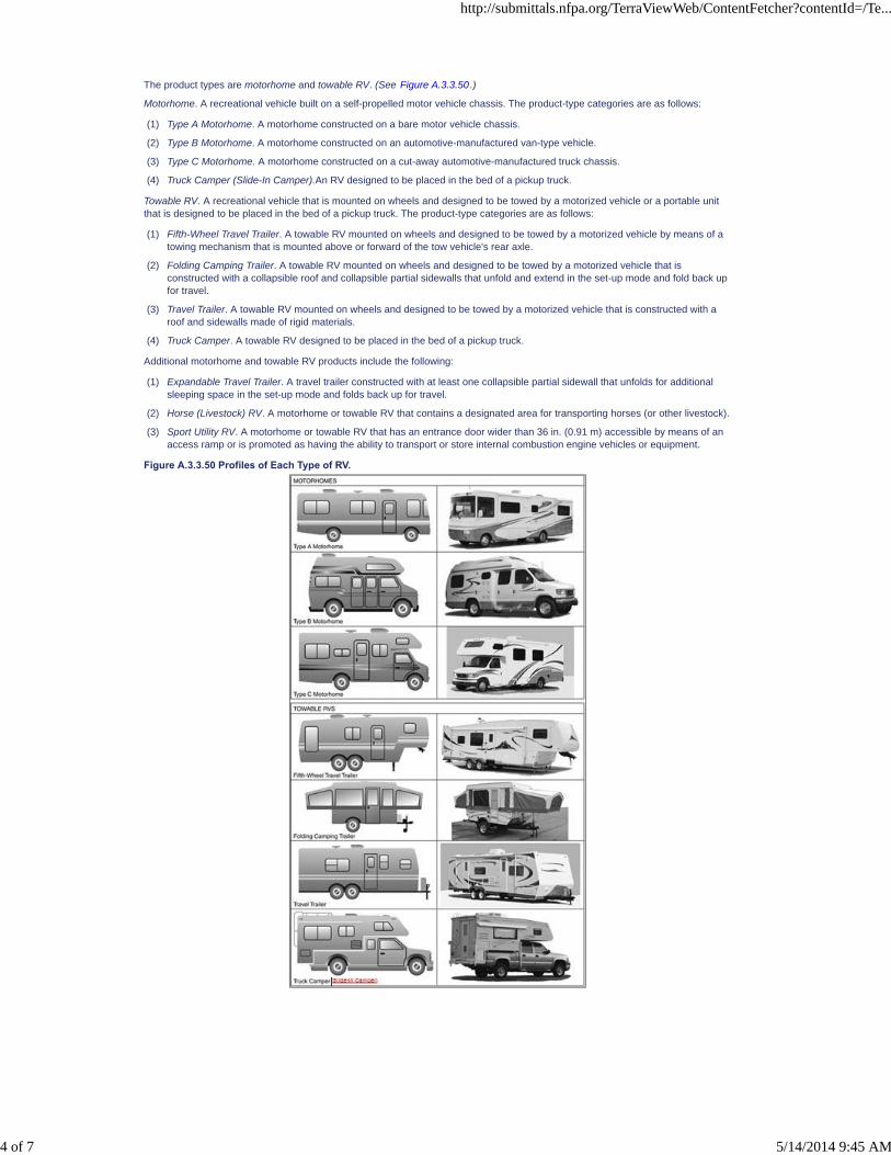
The product types are motorhome and towable RV. (See Figure A.3.3.50.)
Motorhome. A recreational vehicle built on a self-propelled motor vehicle chassis. The product-type categories are as follows:
(1) Type A Motorhome. A motorhome constructed on a bare motor vehicle chassis.
(2) Type B Motorhome. A motorhome constructed on an automotive-manufactured van-type vehicle.
(3) Type C Motorhome. A motorhome constructed on a cut-away automotive-manufactured truck chassis.
(4) Truck Camper (Slide-In Camper).An RV designed to be placed in the bed of a pickup truck.
Towable RV. A recreational vehicle that is mounted on wheels and designed to be towed by a motorized vehicle or a portable unitthat is designed to be placed in the bed of a pickup truck. The product-type categories are as follows:
(1) Fifth-Wheel Travel Trailer. A towable RV mounted on wheels and designed to be towed by a motorized vehicle by means of atowing mechanism that is mounted above or forward of the tow vehicle's rear axle.
(2) Folding Camping Trailer. A towable RV mounted on wheels and designed to be towed by a motorized vehicle that isconstructed with a collapsible roof and collapsible partial sidewalls that unfold and extend in the set-up mode and fold back upfor travel.
(3) Travel Trailer. A towable RV mounted on wheels and designed to be towed by a motorized vehicle that is constructed with aroof and sidewalls made of rigid materials.
(4) Truck Camper. A towable RV designed to be placed in the bed of a pickup truck.
Additional motorhome and towable RV products include the following:
(1) Expandable Travel Trailer. A travel trailer constructed with at least one collapsible partial sidewall that unfolds for additionalsleeping space in the set-up mode and folds back up for travel.
(2) Horse (Livestock) RV. A motorhome or towable RV that contains a designated area for transporting horses (or other livestock).
(3) Sport Utility RV. A motorhome or towable RV that has an entrance door wider than 36 in. (0.91 m) accessible by means of anaccess ramp or is promoted as having the ability to transport or store internal combustion engine vehicles or equipment.
Figure A.3.3.50 Profiles of Each Type of RV.
http://submittals.nfpa.org/TerraViewWeb/ContentFetcher?contentId=/Te...
4 of 7 5/14/2014 9:45 AM

A.3.3.53.3 Flexible Drain System.
A liquid waste drainage system (including the trap, strainer, hose, and connectors) with a minimum free waterway of 5⁄8 in. (16 mm)inside diameter (or equivalent passage) is used where authorized under 7.4.7.
A.3.3.54.2 Side-Mounted Fuel Tank.
In determining whether a fuel tank on a trailer or motor home is side-mounted, the fill pipe is not considered a part of the tank.
A.3.3.60 Tubing.
An example of tubing is copper tubing.
A.3.3.63 Vapor Resistant.
Examples of vapor resistant include construction where penetrations, seams, or joints are caulked, sealed, filled, or equivalent.
A.5.2.12
This provision is not to be construed as requiring an automatic changeover device.
A.5.2.19
This section should not apply to unventilated compartment doors containing either door or body side seals and entry doors notcontaining screens or openable windows below the level of the propane discharge outlet(s).
A.5.5.3
This subsection does not apply to diesel filter spout. Unlike gasoline fuel, diesel fuel requires atomization and compression to reachflash point. Therefore, the diesel fuel fill does not require the 3 ft (0.9 m) separation from fuel-burning heating appliances,combustion air inlets, or flue gas outlets.
A.5.5.3.3
A partial obstruction can be created for a swinging door if a portion of the door comes closer than 2 in. (50 mm) to any portion of thevent when the door is fully open. In truck campers, the vent shall not terminate in the box area of the truck.
A.5.7.6.2
For example: (supply duct static pressure) + (0.10 in. water column and return air duct static pressure) - (0.04 in. water column).Numerical total is 0.14 in. water column static pressure.
A.5.7.10
For this test, the register or grille is to be at a temperature of not less than 165°F (74°C) and is to be supported in accordance withthe manufacturer's instructions.
A.5.7.10.2
This subsection should apply to ducted rooftop air-conditioning systems with heat strips or heat pumps where the system does notexceed 175°F (80°C) when tested in accordance with ANSI/UL 484.
A.5.9.7.4
Examples of fuel type identifications are “Gasoline Only” or “Diesel Only.”
A.6.2.1.2
Global SR-8 Hide Deleted
The path from a sleeping area begins at the floor where one leaves a bed (bunk beds, cab-over beds, dinettes, sleeper sofas,etc.). To qualify as a “different path,” the path cannot duplicate another path after 24 in. from a sleeping area. To maintain the pathsize criteria, it is recognized that built-in furniture, cabinets, and so forth, can be part of the path, as long as these items support aminimum of 300 pounds and do not exceed the 36 in. vertical dimension. See Figure A.6.2.1.2 .
Figure A.6.2.1.2 Bed Within 24 in. (610 mm) of the Plane of the Nearest Designated Exit.
http://submittals.nfpa.org/TerraViewWeb/ContentFetcher?contentId=/Te...
5 of 7 5/14/2014 9:45 AM

SR-32 Hide Legislative
A.6.2.5.1
Figure A.6.2.5.1 is useful in explaining the method of measuring the alternate exit in 6.2.5.
Figure A.6.2.5.1 Ellipsoid of Revolution About a Minor Axis.
A.6.3.2
Because some smoke alarms are activated by the gases released when cooking food and can result in an unwanted alarm, thesmoke alarm manufacturer should be consulted regarding the alarm's suitability for operation in close proximity to cookingprocesses.
A.7.1.6.3
Extendable components include power supply assemblies.
A.7.3.7.5
To ensure complete disinfection of the potable water system, it is recommended that the following procedures be followed on a newsystem, one that has not been used for a period of time, or one that could have become contaminated. This procedure is alsorecommended before long periods of storage such as over winter.
(1) Prepare a chlorine solution using 1 gal. (3.8 L) of water and 1⁄4 cup (60 ml) household bleach (sodium hypochlorite solution).With tank empty, pour chlorine solution into the tank. Use 1 gal. (3.8 L) solution for each 15 gal (57 L) of tank capacity. Thisprocedure will result in a residual chlorine concentration of 50 ppm in the water system. If a 100 ppm concentration is required,as discussed in A.7.3.7.5(3), use 1⁄2 cup of household bleach with 1 gal. of water to prepare the chlorine solution. Use 1 gal. ofthe solution for each 15 gal. of tank capacity.
(2) Complete filling of tank with potable water. Open each faucet and run the water until a distinct odor of chlorine can be detectedin the water discharged. Do not forget the hot water taps.
(3) Allow the system to stand for at least 4 hours when disinfecting with 50 ppm residual chlorine. If a shorter time period isdesired, a 100 ppm chlorine concentration should be permitted to stand in the system for at least 1 hour.
(4) Drain and flush with potable water.
Global SR-32 Hide Deleted
A.8.1.1.1
See SAE J684, Couplings, Hitches, and Safety Chains — Automotive Type , Table 1.
http://submittals.nfpa.org/TerraViewWeb/ContentFetcher?contentId=/Te...
6 of 7 5/14/2014 9:45 AM

SR-30 Hide Legislative
SR-31 Hide Legislative
A.8.1.2.2
Figure A.8.1.2.2 shows the method to determine the shortest allowable tongue or A-frame.
Figure A.8.1.2.2 Method of Determining Shortest Tongue or A-Frame.
A.8.4.1.4
Where a breakaway switch and safety chains or cables are provided on the same unit, care should be taken to ensure that thebreakaway switch–actuating cable will not operate the switch until the trailer completely separates from the towing vehicle. Thisincludes failure and disengagement of the hitch mechanism and safety chains or cables and ensures that normal brake control ismaintained until complete separation.The power source for the breakaway device can be the same battery that is used to power theinterior 12 V circuits.
http://submittals.nfpa.org/TerraViewWeb/ContentFetcher?contentId=/Te...
7 of 7 5/14/2014 9:45 AM

NFPA 1192®, Standard on Recreational Vehicles, 2011 Edition
NFPA STANDARDS DEVELOPMENT SITESECOND DRAFT REPORTClosing Date: July 19, 2013 NOTE: All Public Comment must be received by 5:00 p
Quick PrintAnnex B Propane Pipe Sizing
This annex is not a part of the requirements of this NFPA document but is included forinformational purposes only.
http://submittals.nfpa.org/TerraViewWeb/ContentFetcher?contentId=/Te...
1 of 4 5/14/2014 9:45 AM

B.1 Example of Propane Pipe Sizing.
http://submittals.nfpa.org/TerraViewWeb/ContentFetcher?contentId=/Te...
2 of 4 5/14/2014 9:45 AM

To determine the required propane supply pipe sizes for each piping section (A–I) of the typicalexample diagrammed in Figure B.1, assuming a combination propane/natural gas supplysystem, the steps given in Table B.1 should be taken.
Figure B.1 Typical Example of Propane Pipe System Sizing for a Recreational Vehicle.
Table B.1 Example of Determining Propane Supply Pipe Sizes
Figure Sizingby Front Propane Supply Connection Rear Propane Supply Connection
Step 1.Measure thelength of thepiping from thepropane supplyconnection tothe inlet of themost remoteappliance. Step2. In theappropriateTable 5.3.4.2(a)through Table5.3.4.2(d),select thecolumnshowing thatdistance or thenext longerdistance if thetable does notgive the exactlength. In thisexample useTable5.3.4.2(a),since itpresumesusing acombinationpropane/naturalgas pipingsystem usingiron pipe.
Step 3. Use thevertical columnin Table5.3.4.2(a)selected inStep 2 for allpropane pipesizing. For
28 ft (8.5 m) (A + I + C + E + G)
[Total: 82,000 Btu/hr (24,026 W)]
30 ft (9.2 m) column [which for 82,000 Btu/hr(24,026 W) means 1⁄2 in. (13 mm) iron pipe or
3⁄4 in. (19 mm) tubing] 30 ft (9.2 m) columnfront connection
19 ft (5.8 m) (F + E + C + H)
[Total: 82,000 Btu/hr (24,026 W)] 20 ft (6.1 m)column [which for 82,000 Btu/hr
(24,026 W) means 1⁄2 in. (13 mm) iron pipe
or 3⁄4 in. (19 mm) tubing]
20 ft (6.1 m) column rear connection
NominalI.D.Pipe
Tubing
O.D.
NominalI.D.Pipe
TubingO.D.
http://submittals.nfpa.org/TerraViewWeb/ContentFetcher?contentId=/Te...
3 of 4 5/14/2014 9:45 AM

Figure Sizingby Front Propane Supply Connection Rear Propane Supply Connection
each section ofpiping,determine thetotal demandfor that section.In the verticalcolumnselected inStep 2, locatethe Btu/hrdemand equalto or justgreater than thedemand for thatsection of pipe.
Step 4. Choosethe larger sizepiping requiredfrom either thefront or rearpropane supplyconnection. If asingle propanesupplyconnection isprovided, thisstep is notrequired.
PipingSection
Btu/hrDemand(1000s)
WDemand in. mm in. mm
PipingSection
Btu/hrDemand(1000s)
W
Demand in. mm in. mm
A 82 24,026 1⁄2 13 3⁄4 19 A — — — — — —
B 30 8,790 3⁄8 10 1⁄2 13 B 30 8,790 3⁄8 10 1⁄2 13
C 50 14,650 3⁄8 10 5⁄8 16 C 32 9,376 3⁄8 10 1⁄2 13
D 15 4,395 1⁄4 6 3⁄8 10 D 15 4,395 1⁄4 6 3⁄8 10
E 35 10,255 3⁄8 10 5⁄8 16 E 47 13,771 3⁄8 10 5⁄8 16
F — — — — — — F 82 24,026 1⁄2 13 3⁄4 19
G 35 10,255 3⁄8 10 5⁄8 16 G 35 10,255 3⁄8 10 1⁄2 13
H 2 586 1⁄4 6 3⁄8 10 H 2 586 1⁄4 6 3⁄8 10
I 52 15,236 3⁄8 10 5⁄8 16 I 30 8,790 3⁄8 10 1⁄2 13
http://submittals.nfpa.org/TerraViewWeb/ContentFetcher?contentId=/Te...
4 of 4 5/14/2014 9:45 AM

NFPA 1192®, Standard on Recreational Vehicles, 2011 Edition
NFPA STANDARDS DEVELOPMENT SITESECOND DRAFT REPORTClosing Date: July 19, 2013 NOTE: All Public Comment must be received by 5:00 pm EST/EDST on the published Closing Date.
Quick PrintAnnex C Product Listing Standards
This annex is not a part of the requirements of this NFPA document but is included for informational purposes only.
C.1
The following documents are listed here to provide reference information. These documents are not a part of the requirements ofthis standard unless also listed in Chapter 2.
http://submittals.nfpa.org/TerraViewWeb/ContentFetcher?contentId=/Te...
1 of 3 5/14/2014 9:45 AM

C.1.1 Plumbing.
(1) Accumulators (IAPMO TS 4, NSF 61)
(2) Valves, potable water system (IAPMO TS 8, CSA Z240.3.2, NSF 61)
(3) Check valves (water heater) (IAPMO TS 8, CSA Z240.3.2, NSF 61)
(4) City water entry (IAPMO TS 28, NSF 24, CSA Z240.3.2, NSF 61)
(5) City water entry outlet plumbing (CSA B125, CSA B137, NSF 14, NSF 61)
(6) Dump valves (IAPMO TS 30)
(7) DWV continuous waste (ABS) (NSF 14, ASTM F409)
(8) DWV continuous waste (PVC) (NSF 14, ASTM F409)
(9) DWV fittings (ABS) (NSF 14, CSA B1800, ASTM D2661)
(10) DWV fittings (PVC) (NSF 14, CSA B1800, ASTM D2665)
(11) DWV pipe (ABS) (NSF 14, CSA B1800, ASTM D2665)
(12) DWV pipe (PVC) (NSF 14, CSA B1800, ASTM D2661)
(13) DWV purple primer (PVC) (NSF 14, CSA B1800, ASTM D2661)
(14) DWV solvent cement (ABS) (NSF 14, CSA B1800, ASTM D2661)
(15) DWV solvent cement (PVC) (NSF 14, CSA B1800, ASTM D2661)
(16) Faucets (metal) (ASME 112.18.1/CSA B125.1)
(17) Faucets (plastic) (ASME 112.18.1/CSA B125.1)
(18) Fill hose, cap, and vent (IAPMO TS 13 [cap], IAPMO TS 19)
(19) Filters (drinking water) (NSF 42, NSF 53, NSF 58, CSA B483.1)
(20) Freshwater tank (IAPMO TS 4, NSF 14)
(21) Gravity water fill (IAPMO TS 19)
(22) Inlet fittings (non-psi) (NSF 24, NSF 14, IAPMO TS, CSA Z 240.3.2)
(23) Inlet plumbing (soft, non-pressure) (NSF 24, NSF 14, IAPMO TS, CSA Z 240.3.2)
(24) Main system clamp rings (NSF 14, CSA B137, ASTM F877, ASTM 1960, ASTM F2098, ASTM F2159)
(25) Main system fittings (Brass) (NSF 14, CSA B137, NSF 61)
(26) Main system fittings (CPVC) (NSF 14, CSA B137, NSF 61)
(27) Main system fittings (CU) (NSF 14, CSA B137, NSF 61)
(28) Main system fittings (plastic) (NSF 14, CSA B137, NSF 61)
(29) Main system manifolds (NSF 14, IAPMO IGC 109, CSA Z240.3.2, NSF 61)
(30) Main system PEX rings (ASTM F877, ASTM F1960)
(31) Main system pipe (CPVC) (CSA B137/ASTM F493, NSF 61)
(32) Main system pipe (CU) (ASTM B88, ASTM B75, CSA Z240.3.2, NSF 61)
(33) Main system pipe (PEX) (CSA B137, ASTM 876, NSF 61)
(34) Pump fittings (IAPMO TS 15, CSA Z240.3.2, NSF 61)
(35) Outlet plumbing (soft) (NSF 14, CSA B125, NSF 61)
(36) Plumbing fixtures (shower) (IAPMO TS 11, CSA B45, ANSI Z124, NSF 61)
(37) Plumbing fixtures (plastic lave sinks) (IAPMO TS 11, CSA B45, ANSI Z124, NSF 61)
(38) Plumbing fixtures (plastic sinks) (IAPMO TS 11, CSA B45, ANSI Z124, NSF 61)
(39) Plumbing fixtures (SS sinks) (IAPMO TS 20, NSF 61)
(40) Plumbing fixtures (tub/shower) (IAPMO TS 11, CSA B45, ANSI Z124, NSF 61)
(41) Pump strainers (IAPMO TS 28, CSA Z240.3.2, NSF 24, NSF 61)
(42) Pumps, electric (IAPMO TS 14, CSA Z240.3.2, NSF 61)
(43) Pumps, manual (IAPMO TS 15, CSA Z240.3.2, NSF 61)
(44) Relief valves (water heater) (IAPMO TS 8, CSA B140, NSF 61)
(45) Shower drains (IAPMO TS 26)
(46) Tank fittings (NSF 14, NSF 24, CSA B125, CSA B240.3.2, NSF 61)
(47) Tank strainer (IAPMO TS 28, CSA Z240.3.2, NSF 24, NSF 61)
(48) Toilets (NSF 24, CSA B45, IAPMO TS 1, IAPMO TS 24, IAPMO TS 12, IAPMO TS 34m, IAPMO IGC 132)
(49) Waste tank flushing systems (IAPMO TS 27)
(50) Waste tanks (IAPMO TS 2, CSA B45)
(51) Water heaters (ANSI/CSA 4.1, ANSI Z21.10.3/CSA 4.3, NSF 61)
(52) Flexible drainage, waste, and vent connector (IAPMO TS-35)
(53) Potable water plastic piping components (NSF-14)
http://submittals.nfpa.org/TerraViewWeb/ContentFetcher?contentId=/Te...
2 of 3 5/14/2014 9:45 AM
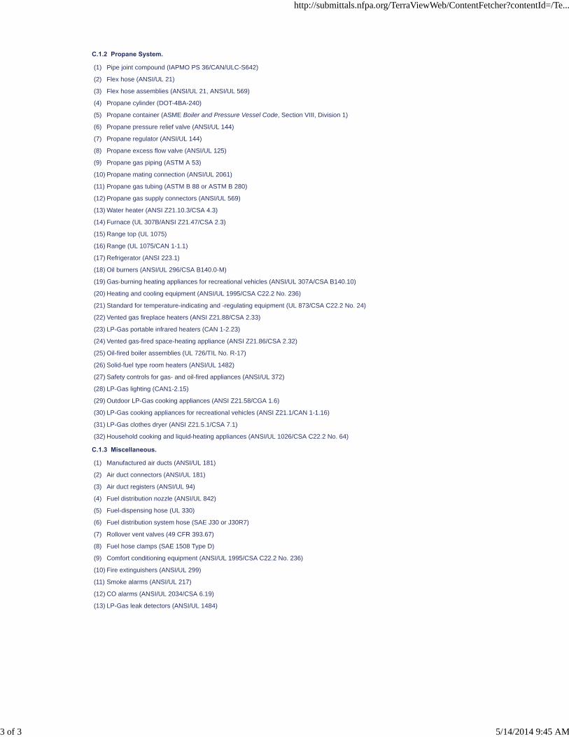
C.1.2 Propane System.
(1) Pipe joint compound (IAPMO PS 36/CAN/ULC-S642)
(2) Flex hose (ANSI/UL 21)
(3) Flex hose assemblies (ANSI/UL 21, ANSI/UL 569)
(4) Propane cylinder (DOT-4BA-240)
(5) Propane container (ASME Boiler and Pressure Vessel Code, Section VIII, Division 1)
(6) Propane pressure relief valve (ANSI/UL 144)
(7) Propane regulator (ANSI/UL 144)
(8) Propane excess flow valve (ANSI/UL 125)
(9) Propane gas piping (ASTM A 53)
(10) Propane mating connection (ANSI/UL 2061)
(11) Propane gas tubing (ASTM B 88 or ASTM B 280)
(12) Propane gas supply connectors (ANSI/UL 569)
(13) Water heater (ANSI Z21.10.3/CSA 4.3)
(14) Furnace (UL 307B/ANSI Z21.47/CSA 2.3)
(15) Range top (UL 1075)
(16) Range (UL 1075/CAN 1-1.1)
(17) Refrigerator (ANSI 223.1)
(18) Oil burners (ANSI/UL 296/CSA B140.0-M)
(19) Gas-burning heating appliances for recreational vehicles (ANSI/UL 307A/CSA B140.10)
(20) Heating and cooling equipment (ANSI/UL 1995/CSA C22.2 No. 236)
(21) Standard for temperature-indicating and -regulating equipment (UL 873/CSA C22.2 No. 24)
(22) Vented gas fireplace heaters (ANSI Z21.88/CSA 2.33)
(23) LP-Gas portable infrared heaters (CAN 1-2.23)
(24) Vented gas-fired space-heating appliance (ANSI Z21.86/CSA 2.32)
(25) Oil-fired boiler assemblies (UL 726/TIL No. R-17)
(26) Solid-fuel type room heaters (ANSI/UL 1482)
(27) Safety controls for gas- and oil-fired appliances (ANSI/UL 372)
(28) LP-Gas lighting (CAN1-2.15)
(29) Outdoor LP-Gas cooking appliances (ANSI Z21.58/CGA 1.6)
(30) LP-Gas cooking appliances for recreational vehicles (ANSI Z21.1/CAN 1-1.16)
(31) LP-Gas clothes dryer (ANSI Z21.5.1/CSA 7.1)
(32) Household cooking and liquid-heating appliances (ANSI/UL 1026/CSA C22.2 No. 64)
C.1.3 Miscellaneous.
(1) Manufactured air ducts (ANSI/UL 181)
(2) Air duct connectors (ANSI/UL 181)
(3) Air duct registers (ANSI/UL 94)
(4) Fuel distribution nozzle (ANSI/UL 842)
(5) Fuel-dispensing hose (UL 330)
(6) Fuel distribution system hose (SAE J30 or J30R7)
(7) Rollover vent valves (49 CFR 393.67)
(8) Fuel hose clamps (SAE 1508 Type D)
(9) Comfort conditioning equipment (ANSI/UL 1995/CSA C22.2 No. 236)
(10) Fire extinguishers (ANSI/UL 299)
(11) Smoke alarms (ANSI/UL 217)
(12) CO alarms (ANSI/UL 2034/CSA 6.19)
(13) LP-Gas leak detectors (ANSI/UL 1484)
http://submittals.nfpa.org/TerraViewWeb/ContentFetcher?contentId=/Te...
3 of 3 5/14/2014 9:45 AM

NFPA 1192®, Standard on Recreational Vehicles, 2011 Edition
NFPA STANDARDS DEVELOPMENT SITESECOND DRAFT REPORTClosing Date: July 19, 2013 NOTE: All Public Comment must be received by 5:00 pm EST/EDST on the published Closing Date.
Quick Print
PCs [1] SR-14 Hide Legislative
SR-33 Hide Legislative
Annex D Informational References
D.1 Referenced Publications.
The documents or portions thereof listed in this annex are referenced within the informational sections of this standard and are notpart of the requirements of this document unless also listed in Chapter 2 for other reasons.
D.1.1 NFPA Publications.
(Reserved)
D.1.2 Other Publications.
D.1.2.1 ANSI Publications.
American National Standards Institute, Inc., 25 West 43rd Street, 4th Floor, New York, NY 10036.
ANSI SI 10, Standard for Use of the International System of Units (SI): The Modern Metric System, 1997.
D.1.2.2 UL Publications.
Underwriters Laboratories Inc., 333 Pfingsten Road, Northbrook, IL 60062-2096.
ANSI/UL 484, Standard for Room Air Conditioners, 2007, Revised revised 2009 2012 .
D.1.2.3 U.S. Government Publications.
U.S. Government Printing Office, Washington, DC 20402.
HUD Interpretive Bulletin A-1-88.
D.2 Informational References.
The following documents or portions thereof are listed here as informational resources only. They are not a part of the requirementsof this document.
D.2.1 UL Publications.
Underwriters Laboratories Inc., 333 Pfingsten Road, Northbrook, IL 60062-2096.
ANSI/UL 2034, Standard for Safety Single and Multiple Station Carbon Monoxide Alarms, 2008, Revised revised 2009.
D.3 References for Extracts in Informational Sections.
NFPA 58, Liquefied Petroleum Gas Code, 2011 2014 edition.
http://submittals.nfpa.org/TerraViewWeb/ContentFetcher?contentId=/Te...
1 of 1 5/14/2014 9:46 AM

Public Comment No. 26-NFPA 1192-2012 [ Global Input ]
NOTE: This Comment received from Keith Jollay was submitted on First Revision (FR) No. 13 to delete thenewly added text to Section 5.4.5 in the First Draft Report. FR 13 was submitted by the Committee to adda new Section 5.4.5 on Flame Failure Devices. FR 13 was balloted by the Committee and appeared in thePDF version of the First Draft Report and was posted on the Document Information Page on the NFPAwebsite. FR 13 was inadvertently omitted from the electronic comment version of the First Draft Report. The text added to NFPA 1192 by FR 13 in the First Draft Report was:
First Revision No. 13:NFPA 1192-2011
[FR 30: FileMaker]
5.4.5 Flame Failure Devices. Fuel-burning ranges and cooktops shall have a flame failure device on
all burners and pilot lights. This requirement shall not become effective until September 1, 2017.
Statement of Problem and Substantiation for Public Comment
RV and residential ranges are attended appliances during use of top burner(s) and provide direct line of sight during use of the appliance. As such, residential ranges are not required to provide a flame failure device on all burners. Thus, our position is the RV range requirements should directly align with the requirements of residential ranges. In addition, US and Canadian standards exist for 3rd party qualification, testing, and certification (CSA, UL, etc.) for ranges. However, no agency standards define or reference proposed flame failure device(s) on top burners, or the testing criteria to qualify the intent of the proposed requirement. The addition of this requirement to NFPA 1192 would be in direct conflict with the available appliance standards as there are no requirements or tests procedures to verify or certify the intent of this requirement through independent 3rd party testing.
Submitter Information Verification
Submitter Full Name: Keith Jollay
Organization: Suburban Mfg. Co.
Street Address:City:State:Zip:Submittal Date: Mon Nov 26 07:53:09 EST 2012
Committee Statement
CommitteeAction:
Accepted
Resolution: SR-17-NFPA 1192-2013
Statement: RV and residential ranges are attended appliances during use of top burner(s) and provide directline of sight during use of the appliance. As such, residential ranges are not required to provide aflame failure device on all burners. Thus, our position is the RV range requirements should directlyalign with the requirements of residential ranges.
In addition, US and Canadian standards exist for 3rd party qualification, testing, and certification(CSA, UL, etc.) for ranges. However, no agency standards define or reference proposed flamefailure device(s) on top burners, or the testing criteria to qualify the intent of the proposedrequirement. The addition of this requirement to NFPA 1192 would be in direct conflict with theavailable appliance standards as there are no requirements or tests procedures to verify or certifythe intent of this requirement through independent 3rd party testing.
National Fire Protection Association Report http://submittals.nfpa.org/TerraViewWeb/ContentFetcher?commentPara...
1 of 33 5/14/2014 9:54 AM

Public Comment No. 14-NFPA 1192-2012 [ Section No. 2.3.1 ]
2.3.1 ANSI Publications. American National Standards Institute, Inc., 25 West 43rd Street, 4th Floor, New York, NY 10036.
ANSI B1.20.1, Pipe Threads, General Purpose (Inch), 2001.
ANSI/RVIA 12V, Low Voltage Systems in Conversion and Recreational Vehicles , 2002.
ANSI TSIC-1 Recommended Practice, Process Controls for Assembly of Wheels on Trailers, 2008.
ANSI Z535, Safety Alerting Standard Series, 2011.
ANSI Z97.1, Glazing Materials Used in Buildings, Safety Performance Specifications and Methods of Test,1994.
Statement of Problem and Substantiation for Public Comment
NFPA Editorial Staff deleted the reference to ANSI/RVIA 12V Low Voltage Systems in Conversion and Recreational Vehicles from section 2.3.1 and re-inserted this reference into a new section 2.3.9 RVIA Publications. If the intent is to identify "where" publications can be obtained then the reference of ANSI TSIC-1 Recommended Practice, Process Controls for Assembly of Wheels on Trailers, 2008 should be moved to its own section because this document is not available from ANSI but rather the National Association of Trailer Manufacturers (NATM) 1320 SW Topeka Blvd., Topeka, KS 66612-1817. If the intent is to just to identify ANSI publication, then the ANSI RVIA 12V standard should remain under section 2.3.1 because it is a ANSI approved standard.
Submitter Information Verification
Submitter Full Name: Kent Perkins
Organization: Recreation Vehicle Industry As
Street Address:City:State:Zip:Submittal Date: Thu Nov 15 08:13:55 EST 2012
Committee Statement
CommitteeAction:
Rejected but see related SR
Resolution: SR-5-NFPA 1192-2013
Statement: Relocate reference to ANSI TSIC-1 Recommended Practice, Process Controls for Assembly ofWheels on Trailers, 2008 to its own section because this document is not available from ANSI butrather the National Association of Trailer Manufacturers (NATM) 1320 SW Topeka Blvd., Topeka,KS 66612-1817
National Fire Protection Association Report http://submittals.nfpa.org/TerraViewWeb/ContentFetcher?commentPara...
2 of 33 5/14/2014 9:54 AM

Public Comment No. 7-NFPA 1192-2012 [ Section No. 2.3.3 ]
2.3.3 ASTM Publications. ASTM International, 100 Barr Harbor Drive, P.O. Box C700, West Conshohocken, PA 19428-2959.
ASTM A 53/A53M, Standard Specifications for Pipe, Steel, Black and Hot-Dipped, Zinc-Coated Welded andSeamless, 2010.
ASTM A 539, Standard Specifications for Electric-Resistance Welded Coiled Steel Tubing for Gas and FuelOil Lines, 1999 (withdrawn 2004).
ASTM B 88, Standard Specifications for Seamless Copper Water Tube, 2009.
ASTM B 280, Specifications for Seamless Copper Tube for Air Conditioning and Refrigeration FieldService, 2008.
ASTM E 84, Standard Test Method for Surface Burning Characteristics of Building Materials, 2011c 2012b .
ASTM E 162, Standard Test Method for Surface Flammability of Materials Using a Radiant Heat EnergySource, 2011a 2012a .
Statement of Problem and Substantiation for Public Comment
Date updates
Submitter Information Verification
Submitter Full Name: Marcelo Hirschler
Organization: GBH International
Street Address:City:State:Zip:Submittal Date: Sun Nov 04 23:08:57 EST 2012
Committee Statement
Committee Action: Accepted
Resolution: SR-4-NFPA 1192-2013
Statement: Date updates
National Fire Protection Association Report http://submittals.nfpa.org/TerraViewWeb/ContentFetcher?commentPara...
3 of 33 5/14/2014 9:54 AM

Public Comment No. 1-NFPA 1192-2012 [ Section No. 2.3.4 ]
2.3.4 CAN/ULC Publications. Underwriters Laboratories of Canada, 7 Underwriters Road, Toronto, Ontario, Canada MIR 3A9.
CAN/ULC-S508, Standard for the Rating and Fire Testing of Fire Extinguishers, 2002 2004, revised 2009(including amendments 1, 2 and 3)
CAN/ULC S504, Standard for Dry Chemical Fire Extinguishers, 2002 2012 (including Amendments 1, 2,and 3).
Statement of Problem and Substantiation for Public Comment
Update referenced standard to most recent edition as indicated.
Submitter Information Verification
Submitter Full Name: John Bender
Organization: UL LLC
Street Address:City:State:Zip:Submittal Date: Wed Oct 24 13:06:33 EDT 2012
Committee Statement
Committee Action: Accepted
Resolution: SR-15-NFPA 1192-2013
Statement: Update referenced standard to most recent edition as indicated.
National Fire Protection Association Report http://submittals.nfpa.org/TerraViewWeb/ContentFetcher?commentPara...
4 of 33 5/14/2014 9:54 AM

Public Comment No. 15-NFPA 1192-2012 [ Section No. 2.3.8 ]
2.3.8 RVIA Publications. Recreation Vehicle Industry Association, 1896 Preston White Drive, Reston, VA 20191.
ANSI/RVIA, Low Voltage Systems in Conversion and Recreational Vehicles , 2011.
Statement of Problem and Substantiation for Public Comment
NFPA Editorial Staff deleted the reference to ANSI/RVIA 12V Low Voltage Systems in Conversion and Recreational Vehicles from section 2.3.1 and re-inserted this reference into a new section 2.3.9 RVIA Publications. If the intent is to identify "where" publications can be obtained then the reference of ANSI TSIC-1 Recommended Practice, Process Controls for Assembly of Wheels on Trailers, 2008 should be moved to its own section because this document is not available from ANSI but rather the National Association of Trailer Manufacturers (NATM) 1320 SW Topeka Blvd., Topeka, KS 66612-1817. If the intent is to just to identify ANSI publication, then the ANSI RVIA 12V standard should remain under section 2.3.1 because it is a ANSI approved standard.
Submitter Information Verification
Submitter Full Name: Kent Perkins
Organization: Recreation Vehicle Industry As
Street Address:City:State:Zip:Submittal Date: Thu Nov 15 08:15:33 EST 2012
Committee Statement
Committee Action: Rejected
Resolution: See committee action on SR5
National Fire Protection Association Report http://submittals.nfpa.org/TerraViewWeb/ContentFetcher?commentPara...
5 of 33 5/14/2014 9:54 AM

Public Comment No. 2-NFPA 1192-2012 [ Section No. 2.3.10 ]
2.3.10 UL Publications. Underwriters Laboratories Inc., 333 Pfingsten Road, Northbrook, IL 60062-2096.
ANSI/UL 21, Standard for LP-Gas Hose, 2007, Revised 2010.
ANSI/UL 94, Standard for Safety Test for Flammability of Plastic Materials for Parts in Devices andAppliances, 1996, Revised 2010 2012 .
ANSI/UL 125, Standard for Flow Control Valves for Anhydrous Ammonia and LP-Gas, 2009, Revised 2011.
ANSI/UL 144, Standard for LP-Gas Regulators, 1999, Revised 2010 2012 .
ANSI/UL 181, Standard for Safety Factory-Made Air Ducts and Air Connectors, 2005, Revised 2008.
ANSI/UL 217, Standard for Single and Multiple Station Smoke Alarms, 2006, Revised 2011 2012 .
ANSI/UL 299, Dry Chemical Extinguishers, 2012.
ANSI/UL 330, Standard for Hose and Hose Assemblies for Dispensing Flammable Liquids, 2009, Revised2011.
ANSI/UL 484, Standard for Room Air Conditioners, 2007, Revised 2011 2012 .
ANSI/UL 569, Standard for Pigtails and Flexible Hose Connectors for LP-Gas, 1995, Revised 2009.
ANSI/UL 723, Test of Surface Burning Characteristics of Burning Materials, 2008, revised 2010.
ANSI/UL 842, Standard for Valves for Flammable Liquids, 2007, revised 2011 .
ANSI/UL 1484, Standard for Residential Gas Detectors, 2000, Revised 2010.
ANSI/UL 2034, Standard for Single and Multiple Station Carbon Monoxide Detectors, 2008, Revised 2009.
ANSI/UL 2061, Standard for Adapters and Cylinder Connection Devices for Portable LP-Gas CylinderAssemblies, 2008, revised 2012 .
ANSI/UL 2227, Standard for Overfilling Prevention Devices, 2007, revised 2009 .
Statement of Problem and Substantiation for Public Comment
Update referenced standard to most recent edition as indicated.
Submitter Information Verification
Submitter Full Name: John Bender
Organization: UL LLC
Street Address:City:State:Zip:Submittal Date: Wed Oct 24 13:07:43 EDT 2012
Committee Statement
Committee Action: Accepted
Resolution: SR-16-NFPA 1192-2013
Statement: Update referenced standard to most recent edition as indicated.
National Fire Protection Association Report http://submittals.nfpa.org/TerraViewWeb/ContentFetcher?commentPara...
6 of 33 5/14/2014 9:54 AM

Public Comment No. 8-NFPA 1192-2012 [ Section No. 3.3.27 ]
3.3.27 Fuel Cell System. The complete aggregate of equipment used to convert chemical fuel into usable electricity and whichtypically consists of a reformer, a stack, a power inverter, and auxiliary equipment.
Statement of Problem and Substantiation for Public Comment
The proposed change provides a better grammatical sentence structure.
Submitter Information Verification
Submitter Full Name: Marcelo Hirschler
Organization: GBH International
Street Address:City:State:Zip:Submittal Date: Sun Nov 04 23:11:08 EST 2012
Committee Statement
CommitteeAction:
Rejected
Resolution: The use of "which" is redundant to the word "typically" and does not grammatically improve thedefinition.
National Fire Protection Association Report http://submittals.nfpa.org/TerraViewWeb/ContentFetcher?commentPara...
7 of 33 5/14/2014 9:54 AM
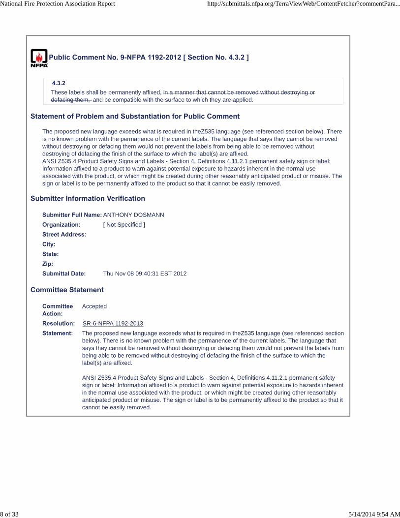
Public Comment No. 9-NFPA 1192-2012 [ Section No. 4.3.2 ]
4.3.2 These labels shall be permanently affixed, in a manner that cannot be removed without destroying ordefacing them, and be compatible with the surface to which they are applied.
Statement of Problem and Substantiation for Public Comment
The proposed new language exceeds what is required in theZ535 language (see referenced section below). There is no known problem with the permanence of the current labels. The language that says they cannot be removed without destroying or defacing them would not prevent the labels from being able to be removed without destroying of defacing the finish of the surface to which the label(s) are affixed.ANSI Z535.4 Product Safety Signs and Labels - Section 4, Definitions 4.11.2.1 permanent safety sign or label: Information affixed to a product to warn against potential exposure to hazards inherent in the normal use associated with the product, or which might be created during other reasonably anticipated product or misuse. The sign or label is to be permanently affixed to the product so that it cannot be easily removed.
Submitter Information Verification
Submitter Full Name: ANTHONY DOSMANN
Organization: [ Not Specified ]
Street Address:City:State:Zip:Submittal Date: Thu Nov 08 09:40:31 EST 2012
Committee Statement
CommitteeAction:
Accepted
Resolution: SR-6-NFPA 1192-2013
Statement: The proposed new language exceeds what is required in theZ535 language (see referenced sectionbelow). There is no known problem with the permanence of the current labels. The language thatsays they cannot be removed without destroying or defacing them would not prevent the labels frombeing able to be removed without destroying of defacing the finish of the surface to which thelabel(s) are affixed.
ANSI Z535.4 Product Safety Signs and Labels - Section 4, Definitions 4.11.2.1 permanent safetysign or label: Information affixed to a product to warn against potential exposure to hazards inherentin the normal use associated with the product, or which might be created during other reasonablyanticipated product or misuse. The sign or label is to be permanently affixed to the product so that itcannot be easily removed.
National Fire Protection Association Report http://submittals.nfpa.org/TerraViewWeb/ContentFetcher?commentPara...
8 of 33 5/14/2014 9:54 AM

Public Comment No. 16-NFPA 1192-2012 [ Section No. 5.8.2.1 ]
5.8.2.1 Each recreational vehicle shall have a label affixed in a visible location at or near each propane supplyconnection or at the end of the piping. The label shall contain the word “Warning” with letters a minimum of1?4 in. (6 mm) high letters and body text a minimum of 1?8 in. (3 mm) high letters on a contrastingbackground, that reads (as appropriate) as shown in Figure 5.8.2.1 . either of the following:
Figure 5.8.2.1
Statement of Problem and Substantiation for Public Comment
The minimum dimension requirements for the word Warning and the body text are incorrect. They should be 1/4 in. and 1/8 in. respectfully not "1.4 in. & 1.8 in."
Submitter Information Verification
Submitter Full Name: Kent Perkins
Organization: Recreation Vehicle Industry As
Street Address:City:State:Zip:Submittal Date: Thu Nov 15 08:17:52 EST 2012
Committee Statement
Committee Action: Rejected
Resolution: The issues have already been addressed in the posted copy of the first draft report.
National Fire Protection Association Report http://submittals.nfpa.org/TerraViewWeb/ContentFetcher?commentPara...
9 of 33 5/14/2014 9:54 AM

Public Comment No. 17-NFPA 1192-2012 [ Section No. 5.8.2.4 ]
5.8.2.4 A permanent warning label with the word words “Warning” and "Danger" with letters a minimum of 1?4 in.(6 mm) high and body text a minimum of 1?8 in. (3 mm) high on a contrasting background shall be affixed ina visible location adjacent to fuel-burning ranges and shall read as shown in Figure 5.8.2.4.
Figure 5.8.2.4
Statement of Problem and Substantiation for Public Comment
The required label (see Figure 5.8.2.4 in the FD - page 39) is actually a duel label and includes both "Warning" and "Danger." Currently the 5.9.2.4 text only addresses "Warning" and should include and identify the term "Danger."
Submitter Information Verification
Submitter Full Name: Kent Perkins
Organization: Recreation Vehicle Industry As
Street Address:City:State:Zip:Submittal Date: Thu Nov 15 08:23:20 EST 2012
Committee Statement
CommitteeAction:
Accepted
Resolution: SR-7-NFPA 1192-2013
National Fire Protection Association Report http://submittals.nfpa.org/TerraViewWeb/ContentFetcher?commentPara...
10 of 33 5/14/2014 9:54 AM
Statement: The required label (see Figure 5.8.2.4 in the FD - page 39) is actually a duel label and includesboth "Warning" and "Danger." Currently the 5.9.2.4 text only addresses "Warning" and shouldinclude and identify the term "Danger."
National Fire Protection Association Report http://submittals.nfpa.org/TerraViewWeb/ContentFetcher?commentPara...
11 of 33 5/14/2014 9:54 AM

Public Comment No. 5-NFPA 1192-2012 [ Section No. 6.1.2 ]
6.1.
2 Combustibility2 Combustibility of Textile or Film Materials.
Where the walls, partitions, or ceilings consist of textile or film materials, such as tent fabric, insectscreening, and flexible plastic weather protection, they shall conform to the requirements of the flamepropagation performance criteria contained in Test Method 1 or Test Method 2, as appropriate, of NFPA701 49 CFR 571.302, paragraphs S4.3 and S5 of Federal Motor Vehicle Safety Standard No. 302,“Flammability of Interior Materials.”
Also, add a reference to NFPA 701 into section 2.2 on referenced NFPA publications: NFPA 701, StandardMethods of Fire Tests for Flame Propagation of Textiles and Films.
Statement of Problem and Substantiation for Public Comment
Experience with FMVSS 302 has demonstrated that it is a very mild test and two references follow: research work by NHTSA (at Southwest Research Institute) and an NFPA consensus document (NFPA 556) specifically devoted to fire safety of road vehicles, including recreational vehicles. The technical committee is correct in its statement that canvas is usually not a problem as an interior finish material, because canvas and other tent fabrics are usually required to comply with NFPA 701 (see, for example http://oceancitymd.gov/fire_department/firemarshal/forms/TentApplication.pdf, http://tentexperts.org/safety/safetyarticles/flammabilityrequirements, http://www.hss.doe.gov/nuclearsafety/techstds/docs/standard/std1088.pdf or http://osfm.fire.ca.gov/strucfireengineer/pdf/flameretardant/FrRegs.pdf ). The same is not true for other film materials, including insect screening and flexible plastic weather protection. Therefore, protection via NFPA 701 is important for such applications. Note that there is a tremendous discrepancy between the requirements for normal interior finish (ASTM E84 or ASTM E162), which are very reasonable, and the almost complete lack of requirements for interior finish if it is “tent fabric, insect screening, and flexible plastic weather protection”, since testing to FMVSS 302 is almost meaningless.
NFPA 701 is a fire test that is specific to textiles and films and is, therefore, fully applicable to its use for “textile or film materials, such as tent fabric, insect screening, and flexible plastic weather protection”, whether they are contained in a recreational vehicle or elsewhere.
A study commissioned by NHTSA at Southwest Research Institute (Battipaglia, K. C., A. L. Griffith, J. P. Huczek, M. L. Janssens, M. A. Miller, and K. R.Willson. October 2003. “Comparison of Fire Properties of Automotive Materials and Evaluation of Performance Levels” San Antonio, TX: Southwest Research Institute, for Department of Transportation, National Highway Traffic Safety Administration) has demonstrated that the fire safety associated with materials tested to FMVSS 302 is very poor.
NFPA 556 is a guide developed by NFPA specifically to look at the fire hazard of road vehicles. It is entitled “Guide on Methods for Evaluating Fire Hazard to Occupants of Passenger Road Vehicles”. NFPA 556 contains a series of tables with fire statistics that show the high level of fire losses associated with road vehicles.
NFPA 556 states as follows in section 5.3.4: “FMVSS 302 provides some measure of fire growth from a match-sized ignition source. However, because it involves only horizontal flame spread, FMVSS 302 provides no direct measure of flame spread on a vertical surface. It does not provide information on how a material might respond to the levels of external radiation input that inevitably occur as a fire grows larger and begins to involve multiple surfaces that exchange radiation.”
Submitter Information Verification
Submitter Full Name: Marcelo Hirschler
Organization: GBH International
Street Address:
National Fire Protection Association Report http://submittals.nfpa.org/TerraViewWeb/ContentFetcher?commentPara...
12 of 33 5/14/2014 9:54 AM
City:State:Zip:Submittal Date: Sun Nov 04 22:53:43 EST 2012
Committee Statement
CommitteeAction:
Rejected
Resolution: No additional evidence has been given that enacting these rules will yield improved safety. Canvasusage in RVs has not proven to be an issue to date. The last time NHTSA reviewed FMVSS 302 forpassenger vehicles, they determined that any revision would yield minimal potential safety benefits.Introducing NFPA 701 guidelines may have negative effects on fire safety. It may encourage the useof fire retardants, which introduce a host of toxicity concerns to both humans and the environment intheir manufacture, transportation, in component manufacture, and in burning vehicles. GM/DOTtesting has shown that significantly more toxic chemicals may be produced when components withfire retardants are burning. NFPA 701, like NFPA 556, are guidelines which are not suitable for motorvehicles. o These guidelines were developed for building fires, for which links between bench-scaletesting and full scale testing have been made. o No conclusive evidence exists which linksbench-scale component level testing to full scale testing for motor vehicles. The Society of FireProtection Engineers (SFPE) handbook states that “bench scale measurements cannot be simplyextrapolated in order to compute the full scale fire. Instead, what is required is either a theory or anempirical relationship that connects the two.” GM/DOT testing has shown that, while an HVACsystem with fire retardants performed better in bench-scale testing, it did not increase the time fortenability in the vehicle tested. National Institute of Standards and Technology (NIST) bus fire testingconcluded that “small-fire scale tests of materials cannot be depended upon to predict the firebehavior in the real world.”
National Fire Protection Association Report http://submittals.nfpa.org/TerraViewWeb/ContentFetcher?commentPara...
13 of 33 5/14/2014 9:54 AM

Public Comment No. 6-NFPA 1192-2012 [ Section No. 6.1.3 ]
6.1.3 Use of Cellular Foam or Foamed Plastic Materials. 6.1.3.1 Cellular foam or foamed plastic materials shall not be used for interior finish (as defined in 3.3.34)in recreational vehicles, except as permitted in 6 . Exception No. 1: Cellular or
1.3.2 or for the incidental uses in 6.1.3.4.
6.1.3.2 A cellular foam or foamed plastic material shall be permitted to be used as interior finish if it hasbeen tested to NFPA 286 and complies with the following:1. During the 40 kW exposure, flames shall not spread to the ceiling.
2. The flame shall not spread to the outer extremity of the sample on any wall or ceiling.
3. Flashover, as defined in NFPA 286, shall not occur.
4. The peak heat release rate throughout the test shall not exceed 800 kW.
6.1.3.3 Cellular foam or foamed plastic materials shall be permitted
on the basis of fire tests that substantiate their combustibility characteristics, for the use intended, in actualfire conditions.Exception No. 2: Incidental use of cellular or foamed materials for
to be used if the material is separated from the interior of the vehicle by an approved thermal barrier ofeither ½ inch (12.7 mm) gypsum wallboard or a material that has been tested in accordance with andmeets the acceptance criteria of both the Temperature Transmission Fire Test and the Integrity Fire Test ofNFPA 275.
6.1.3.4 The cellular or foamed plastic materials shall be permitted to be used for incidental use in molding,trim, splash panels
,
and on doors
shall be permitted.
, but only if the material has a maximum thickness of ½ inch (12.7 mm), a maximum width of 8 inches (204mm) and does not constitute more than 10 percent of the specific area to which it is attached.
Also, add NFPA 275 (Standard Method of Fire Tests for the Evaluation of Thermal Barriers Used overFoam Plastic Insulation) and NFPA 286 (Standard Method of Fire Test for Evaluating Contribution of Walland Ceiling Interior Finish to Room Fire Growth) into chapter 2 on referenced standards.
Additional Proposed Changes
File Name Description ApprovedComment_NFPA_1192_6_1_3_change_only.docx Proposed text for 6.1.3.2 as it should read
Statement of Problem and Substantiation for Public Comment
The proposed wording does not require higher levels of fire performance but simply eliminates the exceptions, which is consistent with the policy in NFPA standards of replacing exceptions by specific instructions.
The exceptions to 6.1.3 are vague and difficult to comply with. Specific information on how to safely use cellular foam or foamed plastic materials exist via test methods and criteria that are used elsewhere (in the Life Safety Code (NFPA 101) and in the building and fire codes) to regulate these materials. NFPA 1192 correctly adopted the experience that indicated that foam plastics cannot be safely tested by means of ASTM E84 (or UL 723) by requiring that interior finish be tested to ASTM E84 (section 6.1.1.1) while excluding foam plastics from such a test. However, this need not exclude all foam plastics, as the exceptions correctly suggest. Typically, foam plastics are allowed to be used only when tested by an appropriate fire test. Since NFPA 286 was first developed, the phrase “fire tests that substantiate their combustibility characteristics” is now typically considered to refer to NFPA 286, the room corner test.
National Fire Protection Association Report http://submittals.nfpa.org/TerraViewWeb/ContentFetcher?commentPara...
14 of 33 5/14/2014 9:54 AM
The new proposed 6.1.3.2 therefore lays out the criteria for approval via the fire test (it has the same criteria that is used in the codes but it eliminates the smoke requirements because NFPA 1192 does not have smoke requirements elsewhere). Note that NFPA 286 has no pass/fail criteria and the criteria must be added into the requirements.
The new proposed 6.1.3.3 is again consistent with the codes and states when foam plastics can safely be used if they are not exposed: when they are separated from the interior by a thermal barrier.
The new proposed 6.1.3.4 quantifies the exception regarding “incidental use”, which is a term that has not been defined in NFPA 1192. In accordance with the wishes of the technical committee, neither fire safety criteria nor material property criteria are included here but there is just a limitation in terms of size, again consistent with what is done in codes.
Submitter Information Verification
Submitter Full Name: Marcelo Hirschler
Organization: GBH International
Street Address:City:State:Zip:Submittal Date: Sun Nov 04 23:00:28 EST 2012
Committee Statement
CommitteeAction:
Rejected
Resolution: No known documentation has been provided suggesting that a different standard is needed toimprove safety.
National Fire Protection Association Report http://submittals.nfpa.org/TerraViewWeb/ContentFetcher?commentPara...
15 of 33 5/14/2014 9:54 AM

Public Comment No. 12-NFPA 1192-2012 [ Sections 6.2.1.1, 6.2.1.2 ]
Sections 6.2.1.1, 6.2.1.26.2.1.1 Each living and sleeping area in a recreational vehicle shall have one primary means of escape and atleast one secondary means of escape.
6.2.1.2* A secondary means of escape shall not be required where the sleeping area or living
Each sleeping area shall have two different paths to escape to the outside of the recreationalvehicle. Where more than one sleeping area is provided and a sleeping area has a door to theoutside of the recreational vehicle , no additional escape is required for this area .
Statement of Problem and Substantiation for Public Comment
The revised wording above accomplishes the goal of providing adequate paths of escape for the recreational vehicle and for each sleeping area in the vehicle. This wording also harmonizes with the wording for NFPA 101 to address bedroom areas.
Submitter Information Verification
Submitter Full Name: David Mihalick
Organization: Thor Industries Inc.
Street Address:City:State:Zip:Submittal Date: Wed Nov 14 11:31:35 EST 2012
Committee Statement
CommitteeAction:
Rejected but see related SR
Resolution: SR-8-NFPA 1192-2013
Statement: The revised wording above accomplishes the goal of providing adequate paths of escape for therecreational vehicle and for each sleeping area in the vehicle. This wording also harmonizes withthe wording of NFPA 101 to address bedroom areas.
National Fire Protection Association Report http://submittals.nfpa.org/TerraViewWeb/ContentFetcher?commentPara...
16 of 33 5/14/2014 9:54 AM

Public Comment No. 22-NFPA 1192-2012 [ Sections 6.2.1.1, 6.2.1.2 ]
Reject the recommendation of the Technical Committee and revise the original proposal as:
6.2.1.1 Each recreational vehicle shall have one primary means of escape and at least onesecondary means of escape.
6.2.1.2 Each sleeping area shall have two means of escape.
Sections 6.2.1.1, 6.2.1.2
6.2.1.1 Each living and sleeping area in a recreational vehicle shall have one primary means of escape and at leastone secondary means of escape.
6.2.1.2* A secondary means of escape shall not be required where the sleeping area or living area has a door to theoutside of the recreational vehicle.
Statement of Problem and Substantiation for Public Comment
The approved proposal would require a door to the outside of the RV from every sleeping area. This is not practical as escape windows have been successfully used in the past. It was also determined that there is not a living area within an RV that doesn’t also serve as a sleeping area, so the reference to living area was deleted to eliminate confusion. Further, living area is not defined. Paragraph 6.2.1.2 modifications are to simplify the requirements, move closer to CSA harmonization and address the State of Oregon by clarifying two means of escape from each sleeping area.
Submitter Information Verification
Submitter Full Name: Kent Perkins
Organization: Recreation Vehicle Industry As
Street Address:City:State:Zip:Submittal Date: Thu Nov 15 08:53:03 EST 2012
Committee Statement
CommitteeAction:
Rejected but see related SR
Resolution: SR-8-NFPA 1192-2013
Statement: The revised wording above accomplishes the goal of providing adequate paths of escape for therecreational vehicle and for each sleeping area in the vehicle. This wording also harmonizes withthe wording of NFPA 101 to address bedroom areas.
National Fire Protection Association Report http://submittals.nfpa.org/TerraViewWeb/ContentFetcher?commentPara...
17 of 33 5/14/2014 9:54 AM

Public Comment No. 19-NFPA 1192-2012 [ Section No. 6.4.7.5 ]
6.4.7.5 An additional listed portable fire extinguisher with a minimum rating of 10-B:C, as defined in NFPA 10,Standard for Portable Fire Extinguishers, , shall be provided in the cargo special transportation area within24 in. (610mm 610 mm ) of the exterior door that serves the cargo special transportation area. .
Statement of Problem and Substantiation for Public Comment
As currently written each individual exterior “cargo” compartment would need a fire extinguisher, technically no matter the compartment size. Therefore the above revision clarifies that the area needing an additional fire extinguisher is only the special transportation area as defined by section 6.4.7.
Submitter Information Verification
Submitter Full Name: Kent Perkins
Organization: Recreation Vehicle Industry As
Street Address:City:State:Zip:Submittal Date: Thu Nov 15 08:28:44 EST 2012
Committee Statement
CommitteeAction:
Accepted
Resolution: SR-9-NFPA 1192-2013
Statement: As currently written each individual exterior “cargo” compartment would need a fire extinguisher,technically no matter the compartment size. Therefore the above revision clarifies that the areaneeding an additional fire extinguisher is only the special transportation area as defined by section6.4.7.
National Fire Protection Association Report http://submittals.nfpa.org/TerraViewWeb/ContentFetcher?commentPara...
18 of 33 5/14/2014 9:54 AM

Public Comment No. 13-NFPA 1192-2012 [ Section No. 6.4.9 ]
6.4.9 9 Protruding Component Operation.6.4.9.1 Any protruding component that is operated by means of an electrical switch or controller that canbe accessible for operation when the vehicle is in transit, shall comply with the following:
(1) Be provided with momentary switching with nonlatching circuitry or the equivalent
Not
(2) Be interlocked to the transmission circuit and not be capable of activation while the vehicle is in
motion
(3) gear when installed on a motorhome.
(4) Not be capable of unintentional activation when installed on a towable RV.
Statement of Problem and Substantiation for Public Comment
Momentary switching for all protruding components should be mandatory and need to remain as part of the standard. Unintentional activation also needs to be prevented. Due to the operational differences between motor homes and trailers the unintentional activation requirement needs to be treated separately to allow it to be accomplished.
Submitter Information Verification
Submitter Full Name: David Mihalick
Organization: Thor Industries Inc.
Street Address:City:State:Zip:Submittal Date: Wed Nov 14 11:33:31 EST 2012
Committee Statement
CommitteeAction:
Rejected but see related SR
Resolution: SR-10-NFPA 1192-2013
Statement: This limits unintentional activation to all the components while in motion and narrows the scopeof momentary latching to the slide-outs and power beds.
National Fire Protection Association Report http://submittals.nfpa.org/TerraViewWeb/ContentFetcher?commentPara...
19 of 33 5/14/2014 9:54 AM

Public Comment No. 18-NFPA 1192-2012 [ Section No. 6.4.9 ]
6.4.9 9 Protrouding Component Operation.Any protruding component (i.e, awning, landing gear, level system or slide outs) that is operated by meansof an electrical switch or controller accessible for operation when the vehicle is in transit, shall comply withthe following:
(1) Be provided with momentary switching with nonlatching circuitry or the equivalent
(2) Not be capable of unintentional activation while the vehicle is in motion
Statement of Problem and Substantiation for Public Comment
The recommendation appears to remove the title from 6.4.9. This would result in a change to the current format that all three digit code numbers have a title within NFPA 1192. The term “any” protruding component is too broad and therefore by adding the specific items that qualify as protruding components helps clarify this requirement. When this requirement was proposed, the intent was for application to motor homes only. In subsequent discussions, we felt it should also apply to towables. However, installing systems on trailers that are based on the movement of the vehicle is technologically impracticable. Unintentional activation was the bases for the proposal and this comment, if accepted, would clarify this. Specific methods of how to prevent accidental operation should be left to the market place.
Submitter Information Verification
Submitter Full Name: Kent Perkins
Organization: Recreation Vehicle Industry As
Street Address:City:State:Zip:Submittal Date: Thu Nov 15 08:25:37 EST 2012
Committee Statement
CommitteeAction:
Rejected but see related SR
Resolution: SR-10-NFPA 1192-2013
Statement: This limits unintentional activation to all the components while in motion and narrows the scopeof momentary latching to the slide-outs and power beds.
National Fire Protection Association Report http://submittals.nfpa.org/TerraViewWeb/ContentFetcher?commentPara...
20 of 33 5/14/2014 9:54 AM

Public Comment No. 21-NFPA 1192-2012 [ New Section after 7.3.6.3 ]
Re-insert existing NFPA 1192 2011 Section 7.3.6.3 as new 7.3.6.4 and renumber the rest of the section asnecessary.
7.3.6.4 Piping systems shall be sized to provide a quantity of water to each plumbing fixture at a flow rateto keep the fixture in a clean and sanitary condition without backflow or siphonage.
Statement of Problem and Substantiation for Public Comment
The 2011 7.3.6.3 requirement was deleted with no rationale provided in the FR statement and needs to be retained in order to address necessary sizing and flow rate.
Submitter Information Verification
Submitter Full Name: Kent Perkins
Organization: Recreation Vehicle Industry As
Street Address:City:State:Zip:Submittal Date: Thu Nov 15 08:31:35 EST 2012
Committee Statement
CommitteeAction:
Rejected
Resolution: Section 7.3.6.4 does not provide quantifying values and a design table is currently in thestandard which is to be utilized for sizing of piping.
National Fire Protection Association Report http://submittals.nfpa.org/TerraViewWeb/ContentFetcher?commentPara...
21 of 33 5/14/2014 9:54 AM

Public Comment No. 23-NFPA 1192-2012 [ Section No. 7.5.3.7 ]
7.5.3.7 8 A caution label containing the word “Caution” with letters a minimum of 1/4 in. (6 mm) high and body text aminimum of 1/8 in. (3 mm) high on a contrasting background shall be affixed in a visible location adjacent tothe tank flush valve inlet and shall read as follows:
CAUTION
Do not use the tank flush valve unless the fullway termination valve is in the open position. May result inan unsanitary condition leading to illness or personal injury.
Statement of Problem and Substantiation for Public Comment
Editorial – the Technical Committee recommendation states – Add new section 7.5.3.8 to read as follows:
Submitter Information Verification
Submitter Full Name: Kent Perkins
Organization: Recreation Vehicle Industry As
Street Address:City:State:Zip:Submittal Date: Thu Nov 15 08:54:41 EST 2012
Committee Statement
Committee Action: Rejected
Resolution: NFPA editing issue
National Fire Protection Association Report http://submittals.nfpa.org/TerraViewWeb/ContentFetcher?commentPara...
22 of 33 5/14/2014 9:54 AM

Public Comment No. 11-NFPA 1192-2012 [ Section No. 7.7.2.4 ]
7.7.2.4 The potable-water storage tank shall be subjected to a static water test for 15 minutes by filling the systemwith water to overflow with no evidence of leaks.
Statement of Problem and Substantiation for Public Comment
FR 67 (7.3.7.1) already addresses the concerns regarding potential water leaks involving potable water storage tanks by establish criteria for support and securement. In addition, these tanks are already required to be pressure tested by the respective listing standard for tank integrity.
Submitter Information Verification
Submitter Full Name: David Mihalick
Organization: Thor Industries Inc.
Street Address:City:State:Zip:Submittal Date: Wed Nov 14 11:30:29 EST 2012
Committee Statement
CommitteeAction:
Rejected but see related SR
Resolution: SR-18-NFPA 1192-2013
Statement: FR 67 (7.3.7.1) already addresses the concerns regarding potential water leaks involving potablewater storage tanks by establish criteria for support and securement. In addition, these tanks arealready required to be pressure tested by the respective listing standard for tank integrity.
National Fire Protection Association Report http://submittals.nfpa.org/TerraViewWeb/ContentFetcher?commentPara...
23 of 33 5/14/2014 9:54 AM

Public Comment No. 24-NFPA 1192-2012 [ Sections 7.7.2.4, 7.7.2.5 ]
Reject this recommendation.
7.7.2.4 The potable-water storage tank shall be subjected to a static water test for 15 minutesby filling the system with
water to overflow with no evidence of leaks.
Add new section 7.7.2.5 to read as follows:
7.7.2.5 The entire pressurized water distribution system shall be subjected to a flow test bypressurizing the system with
water at a minimum of the demand pump pressure and operating each fixture faucet (both hot andcold) with no evidence of leaks .
Sections 7.7.2.4, 7.7.2.5
7.7.2.4 The potable-water storage tank shall be subjected to a static water test for 15 minutes by filling the systemwith water to overflow with no evidence of leaks.
7.7.2.5 The entire pressurized water distribution system shall be subjected to a flow test by pressurizing the systemwith water at a minimum of the demand pump pressure and operating each fixture faucet (both hot andcold) with no evidence of leaks.
Statement of Problem and Substantiation for Public Comment
FR 67 (7.3.7.1) already addresses the concerns regarding potential water leaks involving potable water storage tanks by establishing criteria for support and securement. In addition, these tanks are already required to be pressure tested by the respective listing standard for tank integrity. The original proposal also did not include any empirical data to support the need for these additional tests, and testing by RV manufacturers shows this is not an area where leaks are occurring. Finally the environmental impact from the tremendous amount of water needed to perform these tests on an ongoing basis is not justified nor a sustainable practice.
Submitter Information Verification
Submitter Full Name: Kent Perkins
Organization: Recreation Vehicle Industry As
Street Address:City:State:Zip:Submittal Date: Thu Nov 15 08:55:33 EST 2012
Committee Statement
CommitteeAction:
Rejected but see related SR
Resolution: SR-18-NFPA 1192-2013
Statement: FR 67 (7.3.7.1) already addresses the concerns regarding potential water leaks involving potablewater storage tanks by establish criteria for support and securement. In addition, these tanks arealready required to be pressure tested by the respective listing standard for tank integrity.
National Fire Protection Association Report http://submittals.nfpa.org/TerraViewWeb/ContentFetcher?commentPara...
24 of 33 5/14/2014 9:54 AM

Public Comment No. 10-NFPA 1192-2012 [ Section No. 7.7.2.5 ]
7.7.2.5 The entire pressurized water distribution system shall be subjected to a flow test by pressurizing thesystem with water at a minimum of the demand pump pressure and operating each fixture faucet (both hotand cold) with no evidence of leaks.
Statement of Problem and Substantiation for Public Comment
Current Section 7.7.2 addresses safety concerns due to potable water system failure by requiring the plumbing system be tested with air or water. Present testing does not require a potable water fixture flow test, and the original proposal did not include it. The need for such a test is not supported by empirical data, would not improve safety and the resulting volume of water needed to satisfy this requirement far outweighs the potential benefit.
Submitter Information Verification
Submitter Full Name: Jerome Hoover
Organization: Navistar RV LLC
Street Address:City:State:Zip:Submittal Date: Tue Nov 13 09:09:54 EST 2012
Committee Statement
CommitteeAction:
Rejected but see related SR
Resolution: SR-19-NFPA 1192-2013
Statement: Current Section 7.7.2 addresses safety concerns due to potable water system failure by requiringthe plumbing system be tested with air or water. Present testing does not require a potable waterfixture flow test, and the original proposal did not include it. The need for such a test is notsupported by empirical data, would not improve safety and the resulting volume of water needed tosatisfy this requirement far outweighs the potential benefit.
National Fire Protection Association Report http://submittals.nfpa.org/TerraViewWeb/ContentFetcher?commentPara...
25 of 33 5/14/2014 9:54 AM
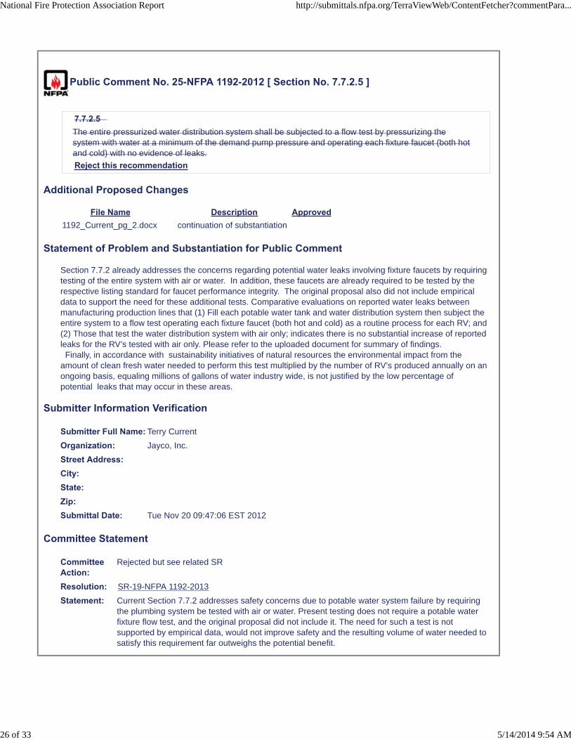
Public Comment No. 25-NFPA 1192-2012 [ Section No. 7.7.2.5 ]
7.7.2.5 The entire pressurized water distribution system shall be subjected to a flow test by pressurizing thesystem with water at a minimum of the demand pump pressure and operating each fixture faucet (both hotand cold) with no evidence of leaks.
Reject this recommendation
Additional Proposed Changes
File Name Description Approved1192_Current_pg_2.docx continuation of substantiation
Statement of Problem and Substantiation for Public Comment
Section 7.7.2 already addresses the concerns regarding potential water leaks involving fixture faucets by requiring testing of the entire system with air or water. In addition, these faucets are already required to be tested by the respective listing standard for faucet performance integrity. The original proposal also did not include empirical data to support the need for these additional tests. Comparative evaluations on reported water leaks between manufacturing production lines that (1) Fill each potable water tank and water distribution system then subject the entire system to a flow test operating each fixture faucet (both hot and cold) as a routine process for each RV; and (2) Those that test the water distribution system with air only; indicates there is no substantial increase of reported leaks for the RV’s tested with air only. Please refer to the uploaded document for summary of findings. Finally, in accordance with sustainability initiatives of natural resources the environmental impact from the amount of clean fresh water needed to perform this test multiplied by the number of RV’s produced annually on an ongoing basis, equaling millions of gallons of water industry wide, is not justified by the low percentage of potential leaks that may occur in these areas.
Submitter Information Verification
Submitter Full Name: Terry Current
Organization: Jayco, Inc.
Street Address:City:State:Zip:Submittal Date: Tue Nov 20 09:47:06 EST 2012
Committee Statement
CommitteeAction:
Rejected but see related SR
Resolution: SR-19-NFPA 1192-2013
Statement: Current Section 7.7.2 addresses safety concerns due to potable water system failure by requiringthe plumbing system be tested with air or water. Present testing does not require a potable waterfixture flow test, and the original proposal did not include it. The need for such a test is notsupported by empirical data, would not improve safety and the resulting volume of water needed tosatisfy this requirement far outweighs the potential benefit.
National Fire Protection Association Report http://submittals.nfpa.org/TerraViewWeb/ContentFetcher?commentPara...
26 of 33 5/14/2014 9:54 AM

Summary of Findings
Comparison of Water Distribution Systems and Fixtures Tested with Water OR Air Only
Line A validates that there are no leaks in the fresh water distribution system using air. Fifth-wheels are built on that
line.
There was only one Fifth-wheel that had a warranty claim involving a leak in the fresh water system. There were 226
Fifth-wheels produced and tested on that line in the review period. The incident rate is 0.4%.
Line B validates that there are no leaks in the fresh water distribution system using water. Fifth-wheels are produced on
that line.
There were seven Fifth-wheels that had warranty claims involving leaks in the fresh water system. There were 3,159
Fifth-wheels produced and tested on that line in the review period. The incident rate is 0.2%.
Line C validates that there are no leaks in the fresh water distribution system using water. Travel Trailers are produced
on that line.
There were 17 Travel Trailers that had warranty claims involving leaks in the fresh water system. There were 5,108
Travel Trailers produced and tested on that line in the review period. The incident rate is 0.3%.
Test
Method
Line # of units
with claims
# of
units
built
Incident
Rate
Air A 1 226 0.4%
Water B 7 3159 0.2%
Water C 17 5108 0.3%

Public Comment No. 20-NFPA 1192-2012 [ Chapter 8 ]
The proposed numbering system of this Chapter should align with the current numberingsequence that is present in the other chapters.Chapter 8 Vehicular Requirements. 8.1 Couplings. 8.1.1 Couplings shall be mounted to the attaching member by bolting, welding, or riveting in such a way that theminimum breaking load (see SAE J684,Couplings, Hitches, and Safety Chains —Automotive Type, Table 1)in the coupling is safely and adequately transferred to that member.
8.1.2 Couplings shall be equipped with a manually operated mechanism to prevent disengagement of thecoupling while the vehicle is in operation and shall be capable of being padlocked when engaged.
8.1.3 It shall be possible to disengage couplings at any angle in azimuth and elevation between the trailer andthe towing vehicle that can be accomplished by the coupling.
8.1.4 Ball couplings and hitch balls, if supplied, shall be identified as complying with SAE J684, Couplings,Hitches, and Safety Chains —Automotive Type.
8.1.5 Fifth-wheel and gooseneck couplings shall be identified as complying with SAE J2638, Fifth Wheel andGooseneck Attachment Performance Up to 30 000/Lb (13 608/Kg) Trailer GVW.
8.2 Tongues and A-Frames. 8.2.1 If a tongue or A-frame is 40 in. (1000 mm) or less above ground level, as measured on a smooth, levelsurface, its length shall be determined by measuring the distance along the longitudinal axis of the tongueor A-frame from the centerline of the coupling ball socket to the vertical plane of the foremost part of thetrailer body.
8.2.2* The length of the tongue or A-frame shall comply with either of the following:
(1) Be at least 35 in. (900 mm)
(2) Be sufficient to allow a 47 in. (1200 mm) rod pivoted in a horizontal plane about any point on a linerunning vertically through the center of the coupling to make an angle of 41 degrees or less with thecenterline of the recreational vehicle before the end of the rod comes in contact with any part of thefront of the recreational vehicle.
8.3 Safety Chains or Cables. 8.3.1 Trailers (except fifth-wheel trailers) shall be equipped with safety chains or cables for attachment to thetowing vehicle.
8.3.2 Safety chains or cables shall consist of two single lengths or one double length of chain or cable forattachment to two points on the towing vehicle and shall permit compliance with the requirements of themanufacturer’s instructions and as specified in 8.3.6.
National Fire Protection Association Report http://submittals.nfpa.org/TerraViewWeb/ContentFetcher?commentPara...
27 of 33 5/14/2014 9:54 AM

8.3.3 Safety chains shall be made of welded steel and safety cables shall be made of galvanized or stainlesssteel strands, either attached to the draw bar or A-frame in a way that, under normal operating conditions,does not allow tension to be placed directly on the means of attachment. The safety chains or cables shallnot be welded to an A-frame or draw bar. The fastening attachment shall be permitted to be welded. Ameans for attaching safety chains or cables shall comply with the following:
(1) Have a rating equal to or greater than the rating of the chains
(2) Be designed to prevent disengagement while the trailer is being towed
8.3.4 Safety chains or cables, including each length of a pair, shall meet the strength requirements of SAE J684,Couplings, Hitches, and Safety Chains —Automotive Type, Table 4.
8.3.5 Safety chains or cables shall be color coded or labeled as follows:
(1) Class 1: silver
(2) Class 2: brass
(3) Class 3: black
(4) Class 4: permanently labeled to indicate proof load rating on each cable and at least one link perlength of chain attached to the recreational vehicle
8.3.6 The slack of each length of safety chain or cable attached to the towed vehicle shall be the same and notmore than necessary to permit the towing vehicle and the towed vehicle to turn at their minimum radius.
8.3.6.1 When passing forward to the towing vehicle, the chains or cables shall be oriented in a way that preventsthe tongue from dropping to the ground and maintains a connection if the primary connecting system fails.
8.3.7 Instructions indicating the recommended method of installing the safety chain or cable on the towing vehicleand attaching the chain or cable to the towed vehicle shall be provided with every trailer.
8.4 Tie-Downs for Truck Campers. Attachment points for tying down a truck camper to a carrying vehicle shall be provided.
8.4.1 Instructions shall be provided with every tie-down and include the recommended method(s) of tying downthe truck camper and the location and type of tie-down required.
8.5 Lamps and Reflectors for Truck Campers. 8.5.1 The lamps specified in 8.5.2 through8.5.6 shall be fitted to truck campers except where they wouldduplicate lighting provided by the carrying vehicle.
8.5.2 Lamp heights shall be measured vertically from the center of the lens to the road surface, with the truckcamper installed on the carrying vehicle
8.5.3 Paired lamps shall be separated by more than one-half the overall width of the vehicle, symmetricallydisposed in a rear elevation with respect to the plane of symmetry of the truck camper, and positioned atthe same height.
National Fire Protection Association Report http://submittals.nfpa.org/TerraViewWeb/ContentFetcher?commentPara...
28 of 33 5/14/2014 9:54 AM

8.5.4 The following lamps shall be fitted to the rear of every truck camper:
(1) Two tail lamps that emit a red light and are 15 in. to 72 in. (380 mm to 1830 mm) above the roadsurface
(2) Two stop signal lamps that emit a red light and are 15 in. to 72 in. (380 mm to 1830 mm) above theroad surface
(3) Two turn signal lamps that emit an amber or red flashing light and are 15 in. to 83 in. (380 mm to 2110mm) above the road surface
(4) One or more license plate lamps positioned to illuminate the rear license plate with white light
(5) On campers more than 79 in. (2000 mm) wide, two clearance lamps positioned as far apart aspracticable but not separated by less than two-thirds the overall width of the vehicle, located as highas practicable and emitting a red light
(6) On campers more than 79 in. (2000 mm) wide, three identification lamps 6 in. to 12 in. (150 mm to 300mm) apart that emit a red light, are located as high as practicable, and are symmetrically disposedabout the centerline of the truck camper
8.5.5 The following lamps shall be fitted to the front of truck campers more than 79 in. (2000 mm) wide:
(1) Two clearance lamps positioned as far apart as practicable but not separated by less than two-thirdsthe overall width of the vehicle, located symmetrically as high as practicable and emitting an amberlight
(2) Three identification lamps 6 in. to 12 in. (150 mm to 300 mm) apart that emit an amber light, arelocated as high as practicable, and are symmetrically disposed about the centerline of the truckcamper
8.5.6 When a truck camper extends beyond the rear of the carrying vehicle box, a lamp emitting a red light shallbe fitted on each side of the truck camper as far to the rear as practicable and at least 15 in. (380 mm)above the road surface when the camper is installed on the carrying vehicle.
8.6 Steps. If provided at the exit(s) of a recreational vehicle, all exterior steps shall have a minimum tread depth of 8in. (200 mm), and the top step shall protrude a minimum of 8 in. (200 mm) from the side of the vehicle.
8.7 Vehicular Connections. 8.7.1 General. Vehicular wiring connection circuits shall be in accordance with 8.7.2 through 8.7.4. Sufficient slack shallbe provided in the wiring connection so that it remains unbroken to the limits of relative movement betweenthe trailer and towing vehicle allowed by the safety chains. Wiring between the connector and the trailerbody shall be protected from physical damage.
8.7.2 Color Coding. Wires shall be identified as follows:
(1) White: ground
(2) Blue: electric brakes
(3) Green: tail and running lamps
(4) Yellow: backup lights or auxiliary use
(5) Black: charging circuit or auxiliary or stop lamps
(6) Brown: right turn signal and stop lamp
(7) Red: left turn signal and stop lamp
8.7.3 Connections for Electric Brake Systems. Recreational vehicles equipped with electric brakes shall employ a connector that has a safety catch toprevent an accidental disconnection and a means of disconnecting without placing the wiring under strain.
National Fire Protection Association Report http://submittals.nfpa.org/TerraViewWeb/ContentFetcher?commentPara...
29 of 33 5/14/2014 9:54 AM

8.7.4 Connections for Nonelectric Brake Systems. Recreational vehicles without electric brakes shall be permitted to use a pin-type connector of the moldedrubber type or equivalent.
8.7.5 Truck Camper. A truck camper shall be connected to vehicle wiring by wiring disconnects readily accessible for service.
8.7.6 Trailer Running Gear. 8.7.6.1 Trailer running gear shall comply with CAN3-D313, Trailer Running Gear, and shall be marked inaccordance with CAN3-D313 by the final assembler or the supplier of the complete running gear.
8.7.6.2 When loaded to the design GVWR and center of gravity, trailers shall impose a load on each running gearassembly not exceeding the gross axle weight rating of each assembly.
8.7.6.3 Service brakes arranged symmetrically on each axle of the trailer shall be used on recreational vehicles ifthe unloaded vehicle mass is greater than 1500 lb (680 kg) or the GVWR as specified on themanufacturer’s nameplate is greater than 2006 lb. (910 kg). Brakes actuated by the inertia overrun of thetrailer on the towing vehicle may be used on trailers up to 6008 lb (2725 kg) or the GVWR.
8.7.6.4* Recreational vehicles with GVWR exceeding 2976 lb (1350 kg) shall be equipped with service brakes thatcan be automatically actuated upon the trailer breaking away from the towing vehicle.
8.7.6.5 When the device is electrically operated, it shall be activated by a power source at least equivalent to a 12V battery with an ampere-hour rating numerically equal to the current draw of the brake magnets, providedthat the brakes have a 12 V rating (e.g., one braked axle with 4 L magnets will draw 6 A and thus thebattery should be at least 12 V, 6 A.h.).
8.7.6.6 Trailers shall also have safety chains or cables attached to the A-frame in accordance with Section 8.3.
8.7.6.7 Hydraulic trailer service brakes shall be designed to ensure there is no loss of hydraulic fluid if the trailerbreaks away from the towing vehicle
8.7.6.8 Where electrically operated brakes are used, they shall be activated by a power source equivalent to orgreater than that provided by a 12 V automobile battery, and wiring shall comply with SAE J1128 or equal.(See Figure 8.7.6.8)
Figure 8.7.6.8
8.8 Additional Requirements. 8.8.1 Except for 120V and porch lamps, lamps other than those specified in Section 8.5shall not be fitted if theywill impair the effectiveness of the lamps specified in Section 8.5.
National Fire Protection Association Report http://submittals.nfpa.org/TerraViewWeb/ContentFetcher?commentPara...
30 of 33 5/14/2014 9:54 AM

8.8.2 When the truck camper width at the front or the rear is significantly less than the maximum overall width,clearance lamps shall be located at the maximum cross-section as near the top as practicable.
8.8.3 Lamps and reflectors shall be removable and reinstallable using standard tools.
8.8.4 The lamps specified in Section 8.5 shall be operated by the same controls that operate the carryingvehicle’s lights. The functioning of these lights shall be coordinated with their counterparts on the carryingvehicle. Identification lamps shall be energized with the clearance and marker lamps.
8.8.5 Installation. 8.8.5.1 Every lamp and reflector shall be oriented on the camper as follows:
(1) In the case of rear and front devices, the photometric axis shall be parallel to the ground and thelongitudinal axis of the camper.
(2) In the case of side markers, the photometric axis shall be parallel to the ground and perpendicular tothe longitudinal axis of the camper.
8.8.5.2 Each device shall be installed in such a way that the required photometric performance is not reduced bythe length of the wiring or by an adjacent structure.
8.8.5.3 If the photometric axis of the installed lamp or reflective device does not comply with 8.8.5, the orientationof the lamp or reflective device shall be acceptable if the photometric characteristics of the installed devicemeet the requirements of 8.8.6.
8.8.6 Lamps (including license plate lamps) and reflectors shall meet the candlepower and test requirements ofTransport Canada’s TSD 108 or the requirements of 49 CFR 571.108, Federal Motor Vehicle SafetyStandard, “Lamps, reflective devices, and associated equipment.”
8.9 Tire and Wheel Assemblies. Tire and wheel assemblies shall be installed on towable recreation vehicles (except for truck campers) inaccordance with ANSI TSIC-1 Recommended Practice, Process Controls for Assembly of Wheels onTrailers.
Statement of Problem and Substantiation for Public Comment
The code reference formatting (numbering) does not match the current format of other chapters within NFPA 1192. For example, currently all three digit numbers have titles. In Chapter 8, sections 8.1 through 8.5 none of the three digit numbers have titles, while within section 8.7 all three digit numbers have titles. Also there appears to be no apparent reason why Section 8.3.5 is not completely underlined as new text in the FR 60 recommendation.
Submitter Information Verification
Submitter Full Name: Kent Perkins
Organization: Recreation Vehicle Industry As
Street Address:City:State:Zip:Submittal Date: Thu Nov 15 08:30:20 EST 2012
Committee Statement
CommitteeAction:
Accepted
National Fire Protection Association Report http://submittals.nfpa.org/TerraViewWeb/ContentFetcher?commentPara...
31 of 33 5/14/2014 9:54 AM

Resolution: SR-13-NFPA 1192-2013
Statement: The code reference formatting (numbering) does not match the current format of other chapterswithin NFPA 1192. For example, currently all three digit numbers have titles. In Chapter 8, sections8.1 through 8.5 none of the three digit numbers have titles, while within section 8.7 all three digitnumbers have titles. Also there appears to be no apparent reason why Section 8.3.5 is notcompletely underlined as new text in the FR 60 recommendation.
National Fire Protection Association Report http://submittals.nfpa.org/TerraViewWeb/ContentFetcher?commentPara...
32 of 33 5/14/2014 9:54 AM

Public Comment No. 3-NFPA 1192-2012 [ Section No. D.1.2.2 ]
D.1.2.2 UL Publications. Underwriters Laboratories Inc., 333 Pfingsten Road, Northbrook, IL 60062-2096.
ANSI/UL 484, Standard for Room Air Conditioners, 2007, Revised 2009 2012 .
Statement of Problem and Substantiation for Public Comment
Update referenced standard to most recent edition as indicated.
Submitter Information Verification
Submitter Full Name: John Bender
Organization: UL LLC
Street Address:City:State:Zip:Submittal Date: Wed Oct 24 13:09:40 EDT 2012
Committee Statement
Committee Action: Accepted
Resolution: SR-14-NFPA 1192-2013
Statement: Update referenced standard to most recent edition as indicated.
National Fire Protection Association Report http://submittals.nfpa.org/TerraViewWeb/ContentFetcher?commentPara...
33 of 33 5/14/2014 9:54 AM

Second Revision No. 17-NFPA 1192-2013 [ Global Input ]
NOTE: This Comment received from Keith Jollay was submitted on First Revision (FR) No. 13 to delete thenewly added text to Section 5.4.5 in the First Draft Report. FR 13 was submitted by the Committee to adda new Section 5.4.5 on Flame Failure Devices. FR 13 was balloted by the Committee and appeared in thePDF version of the First Draft Report and was posted on the Document Information Page on the NFPAwebsite. FR 13 was inadvertently omitted from the electronic comment version of the First Draft Report. The text added to NFPA 1192 by FR 13 in the First Draft Report was:
First Revision No. 13:NFPA 1192-2011
[FR 30: FileMaker]
5.4.5 Flame Failure Devices. Fuel-burning ranges and cooktops shall have a flame failure device on
all burners and pilot lights. This requirement shall not become effective until September 1, 2017.
Submitter Information Verification
Submitter Full Name: [ Not Specified ]
Organization: [ Not Specified ]
Street Address:City:State:Zip:Submittal Date: Fri Mar 29 06:54:47 EDT 2013
Committee Statement
CommitteeStatement:
RV and residential ranges are attended appliances during use of top burner(s) and provide directline of sight during use of the appliance. As such, residential ranges are not required to provide aflame failure device on all burners. Thus, our position is the RV range requirements should directlyalign with the requirements of residential ranges.
In addition, US and Canadian standards exist for 3rd party qualification, testing, and certification(CSA, UL, etc.) for ranges. However, no agency standards define or reference proposed flamefailure device(s) on top burners, or the testing criteria to qualify the intent of the proposedrequirement. The addition of this requirement to NFPA 1192 would be in direct conflict with theavailable appliance standards as there are no requirements or tests procedures to verify or certifythe intent of this requirement through independent 3rd party testing.
ResponseMessage:Public Comment No. 26-NFPA 1192-2012 [Global Input]
Ballot Results
This item has passed ballot
26 Eligible Voters
7 Not Returned
18 Affirmative All
1 Affirmative with Comments
0 Negative with Comments
0 Abstention
National Fire Protection Association Report http://submittals.nfpa.org/TerraViewWeb/ContentFetcher?commentPara...
1 of 153 5/14/2014 9:52 AM

Not ReturnedArnold, Thomas R.
Ballard, Charles N.
Colwell, Jeff D.
Kitchens, John R.
Klein, Richard H.
Mittelstaedt, Jr., Arthur H.
Taylor, Monte L.
Affirmative AllBloom, Christopher J.
Christner, Jeffrey A.
Elliott, Wade
Foster, Dean
Haas, Douglas
Habib, Khaled E.
Harvey, John P.
Hoover, Jerome A.
Hopkins, Bruce A.
Livingston, Bob
Luttich, Mark
Mihalick, David M.
Mulvaney, Doug
Parrott, Kerry
Sinclair, Paul
Staves, Homer A.
Swiecicki, Bruce J.
Woodward, Leslie
Affirmative with CommentJordal, Dale
By voiting affirmative I agree with Keith Jollay substantiation to delete 5.4.5 Flame Failure Devices.
National Fire Protection Association Report http://submittals.nfpa.org/TerraViewWeb/ContentFetcher?commentPara...
2 of 153 5/14/2014 9:52 AM
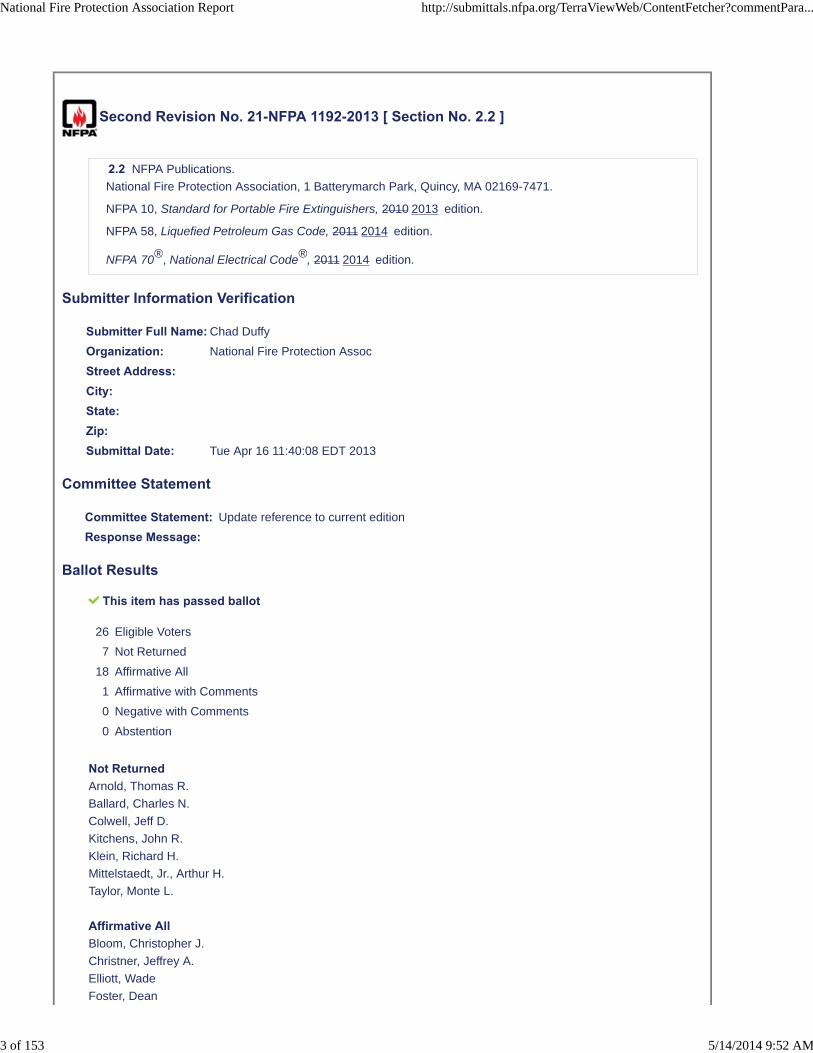
Second Revision No. 21-NFPA 1192-2013 [ Section No. 2.2 ]
2.2 NFPA Publications.
National Fire Protection Association, 1 Batterymarch Park, Quincy, MA 02169-7471.
NFPA 10, Standard for Portable Fire Extinguishers, 2010 2013 edition.
NFPA 58, Liquefied Petroleum Gas Code, 2011 2014 edition.
NFPA 70®, National Electrical Code®, 2011 2014 edition.
Submitter Information Verification
Submitter Full Name: Chad Duffy
Organization: National Fire Protection Assoc
Street Address:City:State:Zip:Submittal Date: Tue Apr 16 11:40:08 EDT 2013
Committee Statement
Committee Statement: Update reference to current edition
Response Message:
Ballot Results
This item has passed ballot
26 Eligible Voters
7 Not Returned
18 Affirmative All
1 Affirmative with Comments
0 Negative with Comments
0 Abstention
Not ReturnedArnold, Thomas R.
Ballard, Charles N.
Colwell, Jeff D.
Kitchens, John R.
Klein, Richard H.
Mittelstaedt, Jr., Arthur H.
Taylor, Monte L.
Affirmative AllBloom, Christopher J.
Christner, Jeffrey A.
Elliott, Wade
Foster, Dean
National Fire Protection Association Report http://submittals.nfpa.org/TerraViewWeb/ContentFetcher?commentPara...
3 of 153 5/14/2014 9:52 AM

Haas, Douglas
Habib, Khaled E.
Harvey, John P.
Hoover, Jerome A.
Hopkins, Bruce A.
Livingston, Bob
Luttich, Mark
Mihalick, David M.
Mulvaney, Doug
Parrott, Kerry
Sinclair, Paul
Staves, Homer A.
Swiecicki, Bruce J.
Woodward, Leslie
Affirmative with CommentJordal, Dale
I understand adding the latest revision to a reference document is a Manual of Style requirement. However I thinkthis practice is misleading as it is typically the listing agency that determines which standard, which revision, andthe effectivity date the change goes into affect.
National Fire Protection Association Report http://submittals.nfpa.org/TerraViewWeb/ContentFetcher?commentPara...
4 of 153 5/14/2014 9:52 AM

Second Revision No. 5-NFPA 1192-2013 [ Section No. 2.3.1 ]
2.3.1 ANSI Publications.
American National Standards Institute, Inc., 25 West 43rd Street, 4th Floor, New York, NY 10036.
ANSI B1.20.1, Pipe Threads, General Purpose (Inch), 2001.
ANSI TSIC-1 Recommended Practice, Process Controls for Assembly of Wheels on Trailers, 2008.
ANSI Z535 , Safety Alerting Standard Series, 2011.
ANSI Z97.1, Glazing Materials Used in Buildings, Safety Performance Specifications and Methods ofTest, 1994.
ANSI Z535, Safety Alerting Standard Series , 2011.
Submitter Information Verification
Submitter Full Name: [ Not Specified ]
Organization: [ Not Specified ]
Street Address:City:State:Zip:Submittal Date: Tue Mar 26 12:32:41 EDT 2013
Committee Statement
CommitteeStatement:
Relocate reference to ANSI TSIC-1 Recommended Practice, Process Controls for Assembly ofWheels on Trailers, 2008 to its own section because this document is not available from ANSI butrather the National Association of Trailer Manufacturers (NATM) 1320 SW Topeka Blvd., Topeka,KS 66612-1817
ResponseMessage:Public Comment No. 14-NFPA 1192-2012 [Section No. 2.3.1]
Ballot Results
This item has passed ballot
26 Eligible Voters
7 Not Returned
19 Affirmative All
0 Affirmative with Comments
0 Negative with Comments
0 Abstention
Not ReturnedArnold, Thomas R.
Ballard, Charles N.
Colwell, Jeff D.
Kitchens, John R.
Klein, Richard H.
National Fire Protection Association Report http://submittals.nfpa.org/TerraViewWeb/ContentFetcher?commentPara...
5 of 153 5/14/2014 9:52 AM

Mittelstaedt, Jr., Arthur H.
Taylor, Monte L.
Affirmative AllBloom, Christopher J.
Christner, Jeffrey A.
Elliott, Wade
Foster, Dean
Haas, Douglas
Habib, Khaled E.
Harvey, John P.
Hoover, Jerome A.
Hopkins, Bruce A.
Jordal, Dale
Livingston, Bob
Luttich, Mark
Mihalick, David M.
Mulvaney, Doug
Parrott, Kerry
Sinclair, Paul
Staves, Homer A.
Swiecicki, Bruce J.
Woodward, Leslie
National Fire Protection Association Report http://submittals.nfpa.org/TerraViewWeb/ContentFetcher?commentPara...
6 of 153 5/14/2014 9:52 AM

Second Revision No. 4-NFPA 1192-2013 [ Section No. 2.3.3 ]
2.3.3 ASTM Publications.
ASTM International, 100 Barr Harbor Drive, P.O. Box C700, West Conshohocken, PA 19428-2959.
ASTM A 53/A53M, Standard Specifications for Pipe, Steel, Black and Hot-Dipped, Zinc-Coated Weldedand Seamless, 2010.
ASTM A 539, Standard Specifications for Electric-Resistance Welded Coiled Steel Tubing for Gas andFuel Oil Lines, 1999 (withdrawn 2004).
ASTM B 88, Standard Specifications for Seamless Copper Water Tube, 2009.
ASTM B 280, Specifications for Seamless Copper Tube for Air Conditioning and Refrigeration FieldService, 2008.
ASTM E 84, Standard Test Method for Surface Burning Characteristics of Building Materials,2011c 2012b .
ASTM E 162, Standard Test Method for Surface Flammability of Materials Using a Radiant Heat EnergySource, 2011a 2012a .
Submitter Information Verification
Submitter Full Name: [ Not Specified ]
Organization: [ Not Specified ]
Street Address:City:State:Zip:Submittal Date: Tue Mar 26 12:09:10 EDT 2013
Committee Statement
Committee Statement: Date updates
Response Message:Public Comment No. 7-NFPA 1192-2012 [Section No. 2.3.3]
Ballot Results
This item has passed ballot
26 Eligible Voters
7 Not Returned
18 Affirmative All
1 Affirmative with Comments
0 Negative with Comments
0 Abstention
Not ReturnedArnold, Thomas R.
Ballard, Charles N.
Colwell, Jeff D.
Kitchens, John R.
National Fire Protection Association Report http://submittals.nfpa.org/TerraViewWeb/ContentFetcher?commentPara...
7 of 153 5/14/2014 9:52 AM

Klein, Richard H.
Mittelstaedt, Jr., Arthur H.
Taylor, Monte L.
Affirmative AllBloom, Christopher J.
Christner, Jeffrey A.
Elliott, Wade
Foster, Dean
Haas, Douglas
Habib, Khaled E.
Harvey, John P.
Hoover, Jerome A.
Hopkins, Bruce A.
Livingston, Bob
Luttich, Mark
Mihalick, David M.
Mulvaney, Doug
Parrott, Kerry
Sinclair, Paul
Staves, Homer A.
Swiecicki, Bruce J.
Woodward, Leslie
Affirmative with CommentJordal, Dale
I understand adding the latest revision to a reference document is a Manual of Style requirement. However I thinkthis practice is misleading, as it is typically the listing agency that determines which standard, which revision, andthe effectivity date the change goes into affect.
National Fire Protection Association Report http://submittals.nfpa.org/TerraViewWeb/ContentFetcher?commentPara...
8 of 153 5/14/2014 9:52 AM

Second Revision No. 15-NFPA 1192-2013 [ Section No. 2.3.4 ]
2.3.4 CAN/ULC Publications.
Underwriters Laboratories of Canada, 7 Underwriters Road, Toronto, Ontario, Canada MIR 3A9 ON, MIR3A9, Canada .
CAN/ULC-S508, Standard for the Rating and Fire Testing of Fire Extinguishers,2002 2004, revised 2009(including amendments 1, 2, and 3)
CAN/ULC S504, Standard for Dry Chemical Fire Extinguishers, 2002 (including Amendments 2012(including amendments 1, 2, and 3).
Submitter Information Verification
Submitter Full Name: [ Not Specified ]
Organization: [ Not Specified ]
Street Address:City:State:Zip:Submittal Date: Tue Mar 26 18:14:55 EDT 2013
Committee Statement
Committee Statement: Update referenced standard to most recent edition as indicated.
Response Message:Public Comment No. 1-NFPA 1192-2012 [Section No. 2.3.4]
Ballot Results
This item has passed ballot
26 Eligible Voters
7 Not Returned
18 Affirmative All
1 Affirmative with Comments
0 Negative with Comments
0 Abstention
Not ReturnedArnold, Thomas R.
Ballard, Charles N.
Colwell, Jeff D.
Kitchens, John R.
Klein, Richard H.
Mittelstaedt, Jr., Arthur H.
Taylor, Monte L.
Affirmative AllBloom, Christopher J.
Christner, Jeffrey A.
National Fire Protection Association Report http://submittals.nfpa.org/TerraViewWeb/ContentFetcher?commentPara...
9 of 153 5/14/2014 9:52 AM

Elliott, Wade
Foster, Dean
Haas, Douglas
Habib, Khaled E.
Harvey, John P.
Hoover, Jerome A.
Hopkins, Bruce A.
Livingston, Bob
Luttich, Mark
Mihalick, David M.
Mulvaney, Doug
Parrott, Kerry
Sinclair, Paul
Staves, Homer A.
Swiecicki, Bruce J.
Woodward, Leslie
Affirmative with CommentJordal, Dale
I understand adding the latest revision to a reference document is a Manual of Style requirement. However I thinkthis practice is misleading, as it is typically the listing agency that determines which standard, which revision, aswell as the effectivity date the change goes into affect.
National Fire Protection Association Report http://submittals.nfpa.org/TerraViewWeb/ContentFetcher?commentPara...
10 of 153 5/14/2014 9:52 AM

Second Revision No. 16-NFPA 1192-2013 [ Section No. 2.3.10 ]
2.3.11 UL Publications.
Underwriters Laboratories Inc., 333 Pfingsten Road, Northbrook, IL 60062-2096.
ANSI/UL 21, Standard for LP-Gas Hose, 2007, Revised revised 2010.
ANSI/UL 94, Standard for Safety Test for Flammability of Plastic Materials for Parts in Devices andAppliances, 1996, Revised revised 2010 2012 .
ANSI/UL 125, Standard for Flow Control Valves for Anhydrous Ammonia and LP-Gas, 2009,Revised revised 2011.
ANSI/UL 144, Standard for LP-Gas Regulators, 1999, Revised 2010 2012 .
ANSI/UL 181, Standard for Safety Factory-Made Air Ducts and Air Connectors, 2005, Revised revised2008.
ANSI/UL 217, Standard for Single and Multiple Station Smoke Alarms, 2006, Revised revised 2011 2012 .
ANSI/UL 299, Dry Chemical Extinguishers, 2012.
ANSI/UL 330, Standard for Hose and Hose Assemblies for Dispensing Flammable Liquids, 2009,Revised revised 2011.
ANSI/UL 484, Standard for Room Air Conditioners, 2007, Revised revised 2011 2012 .
ANSI/UL 569, Standard for Pigtails and Flexible Hose Connectors for LP-Gas, 1995, Revised revised2009.
ANSI/UL 723, Test of Surface Burning Characteristics of Burning Materials, 2008, revised 2010.
ANSI/UL 842, Standard for Valves for Flammable Liquids, 2007. , revised 2011.
ANSI/UL 1484, Standard for Residential Gas Detectors, 2000, Revised revised 2010.
ANSI/UL 2034, Standard for Single and Multiple Station Carbon Monoxide Detectors, 2008,Revised revised 2009.
ANSI/UL 2061, Standard for Adapters and Cylinder Connection Devices for Portable LP-Gas CylinderAssemblies, 2008. , revised 2012.
ANSI/UL 2227, Standard for Overfilling Prevention Devices, 2007. , revised 2009.
Submitter Information Verification
Submitter Full Name: [ Not Specified ]
Organization: [ Not Specified ]
Street Address:City:State:Zip:Submittal Date: Tue Mar 26 18:19:28 EDT 2013
Committee Statement
Committee Statement: Update referenced standard to most recent edition as indicated.
Response Message:Public Comment No. 2-NFPA 1192-2012 [Section No. 2.3.10]
Ballot Results
National Fire Protection Association Report http://submittals.nfpa.org/TerraViewWeb/ContentFetcher?commentPara...
11 of 153 5/14/2014 9:52 AM

This item has passed ballot
26 Eligible Voters
7 Not Returned
18 Affirmative All
1 Affirmative with Comments
0 Negative with Comments
0 Abstention
Not ReturnedArnold, Thomas R.
Ballard, Charles N.
Colwell, Jeff D.
Kitchens, John R.
Klein, Richard H.
Mittelstaedt, Jr., Arthur H.
Taylor, Monte L.
Affirmative AllBloom, Christopher J.
Christner, Jeffrey A.
Elliott, Wade
Foster, Dean
Haas, Douglas
Habib, Khaled E.
Harvey, John P.
Hoover, Jerome A.
Hopkins, Bruce A.
Livingston, Bob
Luttich, Mark
Mihalick, David M.
Mulvaney, Doug
Parrott, Kerry
Sinclair, Paul
Staves, Homer A.
Swiecicki, Bruce J.
Woodward, Leslie
Affirmative with CommentJordal, Dale
I understand adding the latest revision to a reference document is a Manual of Style requirement. However I thinkthis practice is misleading, as it is typically the listing agency that determines which standard, which revision, aswell as the effectivity date the change goes into affect.
National Fire Protection Association Report http://submittals.nfpa.org/TerraViewWeb/ContentFetcher?commentPara...
12 of 153 5/14/2014 9:52 AM

Second Revision No. 20-NFPA 1192-2013 [ Section No. 2.4 ]
2.4 References for Extracts in Mandatory Sections.
NFPA 51, Standard for the Design and Installation of Oxygen–Fuel Gas Systems for Welding, Cutting,and Allied Processes, 2007 2013 edition.
NFPA 54, National Fuel Gas Code, 2009 2012 edition.
NFPA 58, Liquefied Petroleum Gas Code, 2011 2014 edition.
NFPA 70®, National Electrical Code®, 2011 2014 edition.
NFPA 211, Standard for Chimneys, Fireplaces, Vents, and Solid Fuel–Burning Appliances, 2010 2013edition.
Submitter Information Verification
Submitter Full Name: Chad Duffy
Organization: National Fire Protection Assoc
Street Address:City:State:Zip:Submittal Date: Tue Apr 16 11:34:59 EDT 2013
Committee Statement
Committee Statement: Update NFPA references for extracted text.
Response Message:
Ballot Results
This item has passed ballot
26 Eligible Voters
7 Not Returned
18 Affirmative All
1 Affirmative with Comments
0 Negative with Comments
0 Abstention
Not ReturnedArnold, Thomas R.
Ballard, Charles N.
Colwell, Jeff D.
Kitchens, John R.
Klein, Richard H.
Mittelstaedt, Jr., Arthur H.
Taylor, Monte L.
Affirmative AllBloom, Christopher J.
National Fire Protection Association Report http://submittals.nfpa.org/TerraViewWeb/ContentFetcher?commentPara...
13 of 153 5/14/2014 9:52 AM

Christner, Jeffrey A.
Elliott, Wade
Foster, Dean
Haas, Douglas
Habib, Khaled E.
Harvey, John P.
Hoover, Jerome A.
Hopkins, Bruce A.
Livingston, Bob
Luttich, Mark
Mihalick, David M.
Mulvaney, Doug
Parrott, Kerry
Sinclair, Paul
Staves, Homer A.
Swiecicki, Bruce J.
Woodward, Leslie
Affirmative with CommentJordal, Dale
I understand adding the latest revision to a reference document is a Manual of Style requirement. However I thinkthis practice is misleading, as it is typically the listing agency that determines which standard, which revision, aswell as the effectivity date the change goes into affect.
National Fire Protection Association Report http://submittals.nfpa.org/TerraViewWeb/ContentFetcher?commentPara...
14 of 153 5/14/2014 9:52 AM

Second Revision No. 22-NFPA 1192-2013 [ Section No. 3.3.1 ]
3.3.1 Accessible.
Having access to but which first requires the removal of a panel, door, or similar covering of the itemdescribed. [54,2009 2012 ]
Submitter Information Verification
Submitter Full Name: Chad Duffy
Organization: National Fire Protection Assoc
Street Address:City:State:Zip:Submittal Date: Tue Apr 16 11:42:09 EDT 2013
Committee Statement
Committee Statement: Update extract reference.
Response Message:
Ballot Results
This item has passed ballot
26 Eligible Voters
7 Not Returned
19 Affirmative All
0 Affirmative with Comments
0 Negative with Comments
0 Abstention
Not ReturnedArnold, Thomas R.
Ballard, Charles N.
Colwell, Jeff D.
Kitchens, John R.
Klein, Richard H.
Mittelstaedt, Jr., Arthur H.
Taylor, Monte L.
Affirmative AllBloom, Christopher J.
Christner, Jeffrey A.
Elliott, Wade
Foster, Dean
Haas, Douglas
Habib, Khaled E.
Harvey, John P.
National Fire Protection Association Report http://submittals.nfpa.org/TerraViewWeb/ContentFetcher?commentPara...
15 of 153 5/14/2014 9:52 AM

Hoover, Jerome A.
Hopkins, Bruce A.
Jordal, Dale
Livingston, Bob
Luttich, Mark
Mihalick, David M.
Mulvaney, Doug
Parrott, Kerry
Sinclair, Paul
Staves, Homer A.
Swiecicki, Bruce J.
Woodward, Leslie
National Fire Protection Association Report http://submittals.nfpa.org/TerraViewWeb/ContentFetcher?commentPara...
16 of 153 5/14/2014 9:52 AM
Second Revision No. 23-NFPA 1192-2013 [ Section No. 3.3.3.2 ]
3.3.3.2 Heat-Producing Appliance.
An appliance that produces heat by utilizing electric energy or by burning fuel. [211,2010 2013 ]
Submitter Information Verification
Submitter Full Name: Chad Duffy
Organization: National Fire Protection Assoc
Street Address:City:State:Zip:Submittal Date: Tue Apr 16 11:43:00 EDT 2013
Committee Statement
Committee Statement: Update extract reference
Response Message:
Ballot Results
This item has passed ballot
26 Eligible Voters
7 Not Returned
19 Affirmative All
0 Affirmative with Comments
0 Negative with Comments
0 Abstention
Not ReturnedArnold, Thomas R.
Ballard, Charles N.
Colwell, Jeff D.
Kitchens, John R.
Klein, Richard H.
Mittelstaedt, Jr., Arthur H.
Taylor, Monte L.
Affirmative AllBloom, Christopher J.
Christner, Jeffrey A.
Elliott, Wade
Foster, Dean
Haas, Douglas
Habib, Khaled E.
Harvey, John P.
Hoover, Jerome A.
National Fire Protection Association Report http://submittals.nfpa.org/TerraViewWeb/ContentFetcher?commentPara...
17 of 153 5/14/2014 9:52 AM

Hopkins, Bruce A.
Jordal, Dale
Livingston, Bob
Luttich, Mark
Mihalick, David M.
Mulvaney, Doug
Parrott, Kerry
Sinclair, Paul
Staves, Homer A.
Swiecicki, Bruce J.
Woodward, Leslie
National Fire Protection Association Report http://submittals.nfpa.org/TerraViewWeb/ContentFetcher?commentPara...
18 of 153 5/14/2014 9:52 AM

Second Revision No. 24-NFPA 1192-2013 [ Section No. 3.3.21 ]
3.3.21 Fixed Maximum Liquid Level Gauge.
A fixed liquid level gauge that indicates the liquid level at which the container is filled to its maximumpermitted filling limit. [58,2011 2014 ]
Submitter Information Verification
Submitter Full Name: Chad Duffy
Organization: National Fire Protection Assoc
Street Address:City:State:Zip:Submittal Date: Tue Apr 16 11:43:54 EDT 2013
Committee Statement
Committee Statement: Update extract reference
Response Message:
Ballot Results
This item has passed ballot
26 Eligible Voters
7 Not Returned
19 Affirmative All
0 Affirmative with Comments
0 Negative with Comments
0 Abstention
Not ReturnedArnold, Thomas R.
Ballard, Charles N.
Colwell, Jeff D.
Kitchens, John R.
Klein, Richard H.
Mittelstaedt, Jr., Arthur H.
Taylor, Monte L.
Affirmative AllBloom, Christopher J.
Christner, Jeffrey A.
Elliott, Wade
Foster, Dean
Haas, Douglas
Habib, Khaled E.
Harvey, John P.
National Fire Protection Association Report http://submittals.nfpa.org/TerraViewWeb/ContentFetcher?commentPara...
19 of 153 5/14/2014 9:52 AM

Hoover, Jerome A.
Hopkins, Bruce A.
Jordal, Dale
Livingston, Bob
Luttich, Mark
Mihalick, David M.
Mulvaney, Doug
Parrott, Kerry
Sinclair, Paul
Staves, Homer A.
Swiecicki, Bruce J.
Woodward, Leslie
National Fire Protection Association Report http://submittals.nfpa.org/TerraViewWeb/ContentFetcher?commentPara...
20 of 153 5/14/2014 9:52 AM

Second Revision No. 25-NFPA 1192-2013 [ Section No. 3.3.38 ]
3.3.38 Overfilling Prevention Device (OPD).
A safety device that is designed to provide an automatic means to prevent the filling of a container inexcess of the maximum permitted filling limit. [58,2011 2014 ]
Submitter Information Verification
Submitter Full Name: Chad Duffy
Organization: National Fire Protection Assoc
Street Address:City:State:Zip:Submittal Date: Tue Apr 16 11:49:57 EDT 2013
Committee Statement
Committee Statement: Update extract reference
Response Message:
Ballot Results
This item has passed ballot
26 Eligible Voters
7 Not Returned
19 Affirmative All
0 Affirmative with Comments
0 Negative with Comments
0 Abstention
Not ReturnedArnold, Thomas R.
Ballard, Charles N.
Colwell, Jeff D.
Kitchens, John R.
Klein, Richard H.
Mittelstaedt, Jr., Arthur H.
Taylor, Monte L.
Affirmative AllBloom, Christopher J.
Christner, Jeffrey A.
Elliott, Wade
Foster, Dean
Haas, Douglas
Habib, Khaled E.
Harvey, John P.
National Fire Protection Association Report http://submittals.nfpa.org/TerraViewWeb/ContentFetcher?commentPara...
21 of 153 5/14/2014 9:52 AM

Hoover, Jerome A.
Hopkins, Bruce A.
Jordal, Dale
Livingston, Bob
Luttich, Mark
Mihalick, David M.
Mulvaney, Doug
Parrott, Kerry
Sinclair, Paul
Staves, Homer A.
Swiecicki, Bruce J.
Woodward, Leslie
National Fire Protection Association Report http://submittals.nfpa.org/TerraViewWeb/ContentFetcher?commentPara...
22 of 153 5/14/2014 9:52 AM
Second Revision No. 26-NFPA 1192-2013 [ Section No. 3.3.39 [Excluding any
Sub-Sections] ]
Rigid conduit of iron, steel, copper, brass, aluminum, or plastic. [54,2009 2012 ]
Submitter Information Verification
Submitter Full Name: Chad Duffy
Organization: National Fire Protection Assoc
Street Address:City:State:Zip:Submittal Date: Tue Apr 16 11:50:38 EDT 2013
Committee Statement
Committee Statement: Update extract reference.
Response Message:
Ballot Results
This item has passed ballot
26 Eligible Voters
7 Not Returned
19 Affirmative All
0 Affirmative with Comments
0 Negative with Comments
0 Abstention
Not ReturnedArnold, Thomas R.
Ballard, Charles N.
Colwell, Jeff D.
Kitchens, John R.
Klein, Richard H.
Mittelstaedt, Jr., Arthur H.
Taylor, Monte L.
Affirmative AllBloom, Christopher J.
Christner, Jeffrey A.
Elliott, Wade
Foster, Dean
Haas, Douglas
Habib, Khaled E.
Harvey, John P.
Hoover, Jerome A.
National Fire Protection Association Report http://submittals.nfpa.org/TerraViewWeb/ContentFetcher?commentPara...
23 of 153 5/14/2014 9:52 AM

Hopkins, Bruce A.
Jordal, Dale
Livingston, Bob
Luttich, Mark
Mihalick, David M.
Mulvaney, Doug
Parrott, Kerry
Sinclair, Paul
Staves, Homer A.
Swiecicki, Bruce J.
Woodward, Leslie
National Fire Protection Association Report http://submittals.nfpa.org/TerraViewWeb/ContentFetcher?commentPara...
24 of 153 5/14/2014 9:52 AM

Second Revision No. 27-NFPA 1192-2013 [ Section No. 3.3.43 ]
3.3.43* Pressure Relief Valve.
A type of pressure relief device designed to both open and close to maintain internal fluid pressure.[58,2011 2014 ]
Submitter Information Verification
Submitter Full Name: Chad Duffy
Organization: National Fire Protection Assoc
Street Address:City:State:Zip:Submittal Date: Tue Apr 16 11:51:31 EDT 2013
Committee Statement
Committee Statement: Update extract reference
Response Message:
Ballot Results
This item has passed ballot
26 Eligible Voters
7 Not Returned
19 Affirmative All
0 Affirmative with Comments
0 Negative with Comments
0 Abstention
Not ReturnedArnold, Thomas R.
Ballard, Charles N.
Colwell, Jeff D.
Kitchens, John R.
Klein, Richard H.
Mittelstaedt, Jr., Arthur H.
Taylor, Monte L.
Affirmative AllBloom, Christopher J.
Christner, Jeffrey A.
Elliott, Wade
Foster, Dean
Haas, Douglas
Habib, Khaled E.
Harvey, John P.
National Fire Protection Association Report http://submittals.nfpa.org/TerraViewWeb/ContentFetcher?commentPara...
25 of 153 5/14/2014 9:52 AM
Hoover, Jerome A.
Hopkins, Bruce A.
Jordal, Dale
Livingston, Bob
Luttich, Mark
Mihalick, David M.
Mulvaney, Doug
Parrott, Kerry
Sinclair, Paul
Staves, Homer A.
Swiecicki, Bruce J.
Woodward, Leslie
National Fire Protection Association Report http://submittals.nfpa.org/TerraViewWeb/ContentFetcher?commentPara...
26 of 153 5/14/2014 9:52 AM

Second Revision No. 28-NFPA 1192-2013 [ Section No. 3.3.60 ]
3.3.60* Tubing.
Semirigid conduit of copper, steel, aluminum, corrugated stainless steel tubing (CSST), or plastic.[54,2009 2012 ]
Submitter Information Verification
Submitter Full Name: Chad Duffy
Organization: National Fire Protection Assoc
Street Address:City:State:Zip:Submittal Date: Tue Apr 16 11:52:35 EDT 2013
Committee Statement
Committee Statement: Update extract reference.
Response Message:
Ballot Results
This item has passed ballot
26 Eligible Voters
7 Not Returned
19 Affirmative All
0 Affirmative with Comments
0 Negative with Comments
0 Abstention
Not ReturnedArnold, Thomas R.
Ballard, Charles N.
Colwell, Jeff D.
Kitchens, John R.
Klein, Richard H.
Mittelstaedt, Jr., Arthur H.
Taylor, Monte L.
Affirmative AllBloom, Christopher J.
Christner, Jeffrey A.
Elliott, Wade
Foster, Dean
Haas, Douglas
Habib, Khaled E.
Harvey, John P.
National Fire Protection Association Report http://submittals.nfpa.org/TerraViewWeb/ContentFetcher?commentPara...
27 of 153 5/14/2014 9:52 AM

Hoover, Jerome A.
Hopkins, Bruce A.
Jordal, Dale
Livingston, Bob
Luttich, Mark
Mihalick, David M.
Mulvaney, Doug
Parrott, Kerry
Sinclair, Paul
Staves, Homer A.
Swiecicki, Bruce J.
Woodward, Leslie
National Fire Protection Association Report http://submittals.nfpa.org/TerraViewWeb/ContentFetcher?commentPara...
28 of 153 5/14/2014 9:52 AM

Second Revision No. 29-NFPA 1192-2013 [ Section No. 3.3.62.1 ]
3.3.62.1 Backflow Check Valve.
A device designed to allow flow in only one direction. [51, 2007 2013 ]
Submitter Information Verification
Submitter Full Name: Chad Duffy
Organization: National Fire Protection Assoc
Street Address:City:State:Zip:Submittal Date: Tue Apr 16 11:53:16 EDT 2013
Committee Statement
Committee Statement: Update extract reference
Response Message:
Ballot Results
This item has passed ballot
26 Eligible Voters
7 Not Returned
19 Affirmative All
0 Affirmative with Comments
0 Negative with Comments
0 Abstention
Not ReturnedArnold, Thomas R.
Ballard, Charles N.
Colwell, Jeff D.
Kitchens, John R.
Klein, Richard H.
Mittelstaedt, Jr., Arthur H.
Taylor, Monte L.
Affirmative AllBloom, Christopher J.
Christner, Jeffrey A.
Elliott, Wade
Foster, Dean
Haas, Douglas
Habib, Khaled E.
Harvey, John P.
Hoover, Jerome A.
National Fire Protection Association Report http://submittals.nfpa.org/TerraViewWeb/ContentFetcher?commentPara...
29 of 153 5/14/2014 9:52 AM

Hopkins, Bruce A.
Jordal, Dale
Livingston, Bob
Luttich, Mark
Mihalick, David M.
Mulvaney, Doug
Parrott, Kerry
Sinclair, Paul
Staves, Homer A.
Swiecicki, Bruce J.
Woodward, Leslie
National Fire Protection Association Report http://submittals.nfpa.org/TerraViewWeb/ContentFetcher?commentPara...
30 of 153 5/14/2014 9:52 AM

Second Revision No. 6-NFPA 1192-2013 [ Section No. 4.3.2 ]
4.3.2
These labels shall be permanently affixed, in a manner that cannot be removed without destroying ordefacing them, and be compatible with the surface to which they are applied.
Submitter Information Verification
Submitter Full Name: [ Not Specified ]
Organization: [ Not Specified ]
Street Address:City:State:Zip:Submittal Date: Tue Mar 26 12:46:25 EDT 2013
Committee Statement
CommitteeStatement:
The proposed new language exceeds what is required in theZ535 language (see referencedsection below). There is no known problem with the permanence of the current labels. The languagethat says they cannot be removed without destroying or defacing them would not prevent the labelsfrom being able to be removed without destroying of defacing the finish of the surface to which thelabel(s) are affixed.
ANSI Z535.4 Product Safety Signs and Labels - Section 4, Definitions 4.11.2.1 permanent safetysign or label: Information affixed to a product to warn against potential exposure to hazards inherentin the normal use associated with the product, or which might be created during other reasonablyanticipated product or misuse. The sign or label is to be permanently affixed to the product so that itcannot be easily removed.
ResponseMessage:Public Comment No. 9-NFPA 1192-2012 [Section No. 4.3.2]
Ballot Results
This item has passed ballot
26 Eligible Voters
7 Not Returned
19 Affirmative All
0 Affirmative with Comments
0 Negative with Comments
0 Abstention
Not ReturnedArnold, Thomas R.
Ballard, Charles N.
Colwell, Jeff D.
Kitchens, John R.
Klein, Richard H.
Mittelstaedt, Jr., Arthur H.
National Fire Protection Association Report http://submittals.nfpa.org/TerraViewWeb/ContentFetcher?commentPara...
31 of 153 5/14/2014 9:52 AM

Taylor, Monte L.
Affirmative AllBloom, Christopher J.
Christner, Jeffrey A.
Elliott, Wade
Foster, Dean
Haas, Douglas
Habib, Khaled E.
Harvey, John P.
Hoover, Jerome A.
Hopkins, Bruce A.
Jordal, Dale
Livingston, Bob
Luttich, Mark
Mihalick, David M.
Mulvaney, Doug
Parrott, Kerry
Sinclair, Paul
Staves, Homer A.
Swiecicki, Bruce J.
Woodward, Leslie
National Fire Protection Association Report http://submittals.nfpa.org/TerraViewWeb/ContentFetcher?commentPara...
32 of 153 5/14/2014 9:52 AM

Second Revision No. 7-NFPA 1192-2013 [ Section No. 5.8.2.4 ]
5.8.2.4
A permanent warning label with the word words “Warning” and “Danger” with letters a minimum of 1⁄4 in.(6 mm) high and body text a minimum of1⁄8 in. (3 mm) high on a contrasting background shall be affixed ina visible location adjacent to fuel-burning ranges and shall read as shown in Figure 5.8.2.4.
Figure 5.8.2.4 Fresh Air Danger/Warning Label.
Submitter Information Verification
Submitter Full Name: [ Not Specified ]
National Fire Protection Association Report http://submittals.nfpa.org/TerraViewWeb/ContentFetcher?commentPara...
33 of 153 5/14/2014 9:52 AM
Organization: [ Not Specified ]
Street Address:City:State:Zip:Submittal Date: Tue Mar 26 13:13:16 EDT 2013
Committee Statement
CommitteeStatement:
The required label (see Figure 5.8.2.4 in the FD - page 39) is actually a duel label and includesboth "Warning" and "Danger." Currently the 5.9.2.4 text only addresses "Warning" and shouldinclude and identify the term "Danger."
ResponseMessage:Public Comment No. 17-NFPA 1192-2012 [Section No. 5.8.2.4]
Ballot Results
This item has passed ballot
26 Eligible Voters
7 Not Returned
19 Affirmative All
0 Affirmative with Comments
0 Negative with Comments
0 Abstention
Not ReturnedArnold, Thomas R.
Ballard, Charles N.
Colwell, Jeff D.
Kitchens, John R.
Klein, Richard H.
Mittelstaedt, Jr., Arthur H.
Taylor, Monte L.
Affirmative AllBloom, Christopher J.
Christner, Jeffrey A.
Elliott, Wade
Foster, Dean
Haas, Douglas
Habib, Khaled E.
Harvey, John P.
Hoover, Jerome A.
Hopkins, Bruce A.
Jordal, Dale
Livingston, Bob
Luttich, Mark
Mihalick, David M.
Mulvaney, Doug
Parrott, Kerry
National Fire Protection Association Report http://submittals.nfpa.org/TerraViewWeb/ContentFetcher?commentPara...
34 of 153 5/14/2014 9:52 AM

Sinclair, Paul
Staves, Homer A.
Swiecicki, Bruce J.
Woodward, Leslie
National Fire Protection Association Report http://submittals.nfpa.org/TerraViewWeb/ContentFetcher?commentPara...
35 of 153 5/14/2014 9:52 AM

Second Revision No. 8-NFPA 1192-2013 [ Sections 6.2.1.1, 6.2.1.2 ]
6.2.1.1
Each living and sleeping area in a recreational vehicle shall have one primary means of escape and atleast one secondary means of escape.
6.2.1.2
A secondary means of escape shall not be required where the sleeping area or living area has adoor Each sleeping area shall have two different paths to escape to the outside of the recreationalvehicle.
6.2.1.2.1
Where more than one sleeping area is provided and a sleeping area has a door as a primary meansof escape to the outside of the recreational vehicle, no additional escape shall be required for thisarea.
Submitter Information Verification
Submitter Full Name: [ Not Specified ]
Organization: [ Not Specified ]
Street Address:City:State:Zip:Submittal Date: Tue Mar 26 14:01:38 EDT 2013
Committee Statement
CommitteeStatement:
The revised wording above accomplishes the goal of providing adequate paths of escape for therecreational vehicle and for each sleeping area in the vehicle. This wording also harmonizes withthe wording of NFPA 101 to address bedroom areas.
ResponseMessage:Public Comment No. 12-NFPA 1192-2012 [Sections 6.2.1.1, 6.2.1.2]
Public Comment No. 22-NFPA 1192-2012 [Sections 6.2.1.1, 6.2.1.2]
Ballot Results
This item has passed ballot
26 Eligible Voters
7 Not Returned
16 Affirmative All
3 Affirmative with Comments
0 Negative with Comments
0 Abstention
Not ReturnedArnold, Thomas R.
Ballard, Charles N.
Colwell, Jeff D.
Kitchens, John R.
National Fire Protection Association Report http://submittals.nfpa.org/TerraViewWeb/ContentFetcher?commentPara...
36 of 153 5/14/2014 9:52 AM

Klein, Richard H.
Mittelstaedt, Jr., Arthur H.
Taylor, Monte L.
Affirmative AllBloom, Christopher J.
Christner, Jeffrey A.
Elliott, Wade
Foster, Dean
Haas, Douglas
Habib, Khaled E.
Harvey, John P.
Hoover, Jerome A.
Livingston, Bob
Luttich, Mark
Mulvaney, Doug
Parrott, Kerry
Sinclair, Paul
Staves, Homer A.
Swiecicki, Bruce J.
Woodward, Leslie
Affirmative with CommentHopkins, Bruce A.
It was not the intent of the Committee action to retain the asterisk of 6.2.1.2 and corresponding Annex A:A.6.2.1.2. The new text of 6.2.1.2.1 now addresses the criteria for means of escape for multiple sleeping areas.The current FIGURE A.6.2.1.2 in the 2011 edition of NFPA 1192 has no correlation to the new text of 6.2.1.2. andtherefore needs to be eliminated, along with respective 6.2.1.2 asterisk. Below is the original comment RVIAsubmitted ? it does not match what was in the Tempe agenda (page 20 Public Comment No. 22) - somehow NFPAstaff added additional (duplicate) 6.2.1.1 & 6.2.1.2* The asterisk (*) was never submitted in the RVIA submittedcomment. It can be seen on Page 20 that there is no asterisk in the first 6.2.1.2. The intent of RVIA?s commentwas not to include the asterisk and thus not include the respective Annex A Figure A.6.2.1.2. From originalcomment: Reject the recommendation of the Technical Committee and revise the original proposal as: 6.2.1.1Each recreational vehicle shall have one primary means of escape and at least one secondary means of escape.6.2.1.2 Each sleeping area shall have two means of escape.
Jordal, Dale
This proposal makes the referenced Annex illustration no longer valid. The statement " two different paths toescape " is vague and needs further definition similar to what the annex provided.
Mihalick, David M.
The asterik on section 6.2.1.2 was inadvertently left in the revision. It and the appendix comments pertaining to itshould be removed as they no longer reflect that section's contents.
National Fire Protection Association Report http://submittals.nfpa.org/TerraViewWeb/ContentFetcher?commentPara...
37 of 153 5/14/2014 9:52 AM

Second Revision No. 9-NFPA 1192-2013 [ Section No. 6.4.7.5 ]
6.4.7.5
An additional listed portable fire extinguisher with a minimum rating of 10-B:C, as defined in NFPA 10,Standard for Portable Fire Extinguishers, , shall be provided in the cargo special transportation areawithin 24 in. (610 mm) of the exterior door that serves the cargo special transportation area. .
Submitter Information Verification
Submitter Full Name: [ Not Specified ]
Organization: [ Not Specified ]
Street Address:City:State:Zip:Submittal Date: Tue Mar 26 16:21:11 EDT 2013
Committee Statement
CommitteeStatement:
As currently written each individual exterior “cargo” compartment would need a fire extinguisher,technically no matter the compartment size. Therefore the above revision clarifies that the areaneeding an additional fire extinguisher is only the special transportation area as defined by section6.4.7.
ResponseMessage:Public Comment No. 19-NFPA 1192-2012 [Section No. 6.4.7.5]
Ballot Results
This item has passed ballot
26 Eligible Voters
7 Not Returned
19 Affirmative All
0 Affirmative with Comments
0 Negative with Comments
0 Abstention
Not ReturnedArnold, Thomas R.
Ballard, Charles N.
Colwell, Jeff D.
Kitchens, John R.
Klein, Richard H.
Mittelstaedt, Jr., Arthur H.
Taylor, Monte L.
Affirmative AllBloom, Christopher J.
Christner, Jeffrey A.
National Fire Protection Association Report http://submittals.nfpa.org/TerraViewWeb/ContentFetcher?commentPara...
38 of 153 5/14/2014 9:52 AM

Elliott, Wade
Foster, Dean
Haas, Douglas
Habib, Khaled E.
Harvey, John P.
Hoover, Jerome A.
Hopkins, Bruce A.
Jordal, Dale
Livingston, Bob
Luttich, Mark
Mihalick, David M.
Mulvaney, Doug
Parrott, Kerry
Sinclair, Paul
Staves, Homer A.
Swiecicki, Bruce J.
Woodward, Leslie
National Fire Protection Association Report http://submittals.nfpa.org/TerraViewWeb/ContentFetcher?commentPara...
39 of 153 5/14/2014 9:52 AM

Second Revision No. 10-NFPA 1192-2013 [ Section No. 6.4.9 ]
6.4.9 Protruding Component Operation.
Any protruding component that is operated The operation of protruding components (i.e., awning, landinggear, level system or slide outs) controlled by means of an electrical switch or controller accessible foroperation when , shall be incapable of activation while the vehicle is in transit, shall comply with thefollowing: .
Be provided with momentary switching with nonlatching circuitry or the equivalent
Not be capable of activation while the vehicle is in motion
6.4.10 Slide-Out Room Activation.
Slide-out room activation shall use only momentary switching with non-latching circuitry or equivalent.
Submitter Information Verification
Submitter Full Name: [ Not Specified ]
Organization: [ Not Specified ]
Street Address:City:State:Zip:Submittal Date: Tue Mar 26 16:29:09 EDT 2013
Committee Statement
CommitteeStatement:
This limits unintentional activation to all the components while in motion and narrows the scopeof momentary latching to the slide-outs and power beds.
ResponseMessage:Public Comment No. 13-NFPA 1192-2012 [Section No. 6.4.9]
Public Comment No. 18-NFPA 1192-2012 [Section No. 6.4.9]
Ballot Results
This item has passed ballot
26 Eligible Voters
7 Not Returned
19 Affirmative All
0 Affirmative with Comments
0 Negative with Comments
0 Abstention
Not ReturnedArnold, Thomas R.
Ballard, Charles N.
Colwell, Jeff D.
Kitchens, John R.
Klein, Richard H.
Mittelstaedt, Jr., Arthur H.
National Fire Protection Association Report http://submittals.nfpa.org/TerraViewWeb/ContentFetcher?commentPara...
40 of 153 5/14/2014 9:52 AM

Taylor, Monte L.
Affirmative AllBloom, Christopher J.
Christner, Jeffrey A.
Elliott, Wade
Foster, Dean
Haas, Douglas
Habib, Khaled E.
Harvey, John P.
Hoover, Jerome A.
Hopkins, Bruce A.
Jordal, Dale
Livingston, Bob
Luttich, Mark
Mihalick, David M.
Mulvaney, Doug
Parrott, Kerry
Sinclair, Paul
Staves, Homer A.
Swiecicki, Bruce J.
Woodward, Leslie
National Fire Protection Association Report http://submittals.nfpa.org/TerraViewWeb/ContentFetcher?commentPara...
41 of 153 5/14/2014 9:52 AM

Second Revision No. 18-NFPA 1192-2013 [ Section No. 7.7.2.4 ]
7.7.2.4
The potable-water storage tank shall be subjected to a static water test for 15 minutes by filling thesystem with water to overflow with no evidence of leaks.
Submitter Information Verification
Submitter Full Name: [ Not Specified ]
Organization: [ Not Specified ]
Street Address:City:State:Zip:Submittal Date: Fri Mar 29 07:56:24 EDT 2013
Committee Statement
CommitteeStatement:
FR 67 (7.3.7.1) already addresses the concerns regarding potential water leaks involving potablewater storage tanks by establish criteria for support and securement. In addition, these tanks arealready required to be pressure tested by the respective listing standard for tank integrity.
ResponseMessage:Public Comment No. 11-NFPA 1192-2012 [Section No. 7.7.2.4]
Public Comment No. 24-NFPA 1192-2012 [Sections 7.7.2.4, 7.7.2.5]
Ballot Results
This item has passed ballot
26 Eligible Voters
7 Not Returned
19 Affirmative All
0 Affirmative with Comments
0 Negative with Comments
0 Abstention
Not ReturnedArnold, Thomas R.
Ballard, Charles N.
Colwell, Jeff D.
Kitchens, John R.
Klein, Richard H.
Mittelstaedt, Jr., Arthur H.
Taylor, Monte L.
Affirmative AllBloom, Christopher J.
Christner, Jeffrey A.
Elliott, Wade
National Fire Protection Association Report http://submittals.nfpa.org/TerraViewWeb/ContentFetcher?commentPara...
42 of 153 5/14/2014 9:52 AM

Foster, Dean
Haas, Douglas
Habib, Khaled E.
Harvey, John P.
Hoover, Jerome A.
Hopkins, Bruce A.
Jordal, Dale
Livingston, Bob
Luttich, Mark
Mihalick, David M.
Mulvaney, Doug
Parrott, Kerry
Sinclair, Paul
Staves, Homer A.
Swiecicki, Bruce J.
Woodward, Leslie
National Fire Protection Association Report http://submittals.nfpa.org/TerraViewWeb/ContentFetcher?commentPara...
43 of 153 5/14/2014 9:52 AM

Second Revision No. 19-NFPA 1192-2013 [ Section No. 7.7.2.5 ]
7.7.2.5
The entire pressurized water distribution system shall be subjected to a flow test by pressurizing thesystem with water at a minimum of the demand pump pressure and operating each fixture faucet (bothhot and cold) with no evidence of leaks.
Submitter Information Verification
Submitter Full Name: [ Not Specified ]
Organization: [ Not Specified ]
Street Address:City:State:Zip:Submittal Date: Fri Mar 29 07:58:15 EDT 2013
Committee Statement
CommitteeStatement:
Current Section 7.7.2 addresses safety concerns due to potable water system failure by requiringthe plumbing system be tested with air or water. Present testing does not require a potable waterfixture flow test, and the original proposal did not include it. The need for such a test is notsupported by empirical data, would not improve safety and the resulting volume of water needed tosatisfy this requirement far outweighs the potential benefit.
ResponseMessage:Public Comment No. 10-NFPA 1192-2012 [Section No. 7.7.2.5]
Public Comment No. 25-NFPA 1192-2012 [Section No. 7.7.2.5]
Ballot Results
This item has passed ballot
26 Eligible Voters
7 Not Returned
19 Affirmative All
0 Affirmative with Comments
0 Negative with Comments
0 Abstention
Not ReturnedArnold, Thomas R.
Ballard, Charles N.
Colwell, Jeff D.
Kitchens, John R.
Klein, Richard H.
Mittelstaedt, Jr., Arthur H.
Taylor, Monte L.
Affirmative All
National Fire Protection Association Report http://submittals.nfpa.org/TerraViewWeb/ContentFetcher?commentPara...
44 of 153 5/14/2014 9:52 AM

Bloom, Christopher J.
Christner, Jeffrey A.
Elliott, Wade
Foster, Dean
Haas, Douglas
Habib, Khaled E.
Harvey, John P.
Hoover, Jerome A.
Hopkins, Bruce A.
Jordal, Dale
Livingston, Bob
Luttich, Mark
Mihalick, David M.
Mulvaney, Doug
Parrott, Kerry
Sinclair, Paul
Staves, Homer A.
Swiecicki, Bruce J.
Woodward, Leslie
National Fire Protection Association Report http://submittals.nfpa.org/TerraViewWeb/ContentFetcher?commentPara...
45 of 153 5/14/2014 9:52 AM

Second Revision No. 13-NFPA 1192-2013 [ Chapter 8 ]
National Fire Protection Association Report http://submittals.nfpa.org/TerraViewWeb/ContentFetcher?commentPara...
46 of 153 5/14/2014 9:52 AM
Chapter 8 Vehicular Requirements.
National Fire Protection Association Report http://submittals.nfpa.org/TerraViewWeb/ContentFetcher?commentPara...
47 of 153 5/14/2014 9:52 AM

8.1 Couplings. Coupling Requirements.
National Fire Protection Association Report http://submittals.nfpa.org/TerraViewWeb/ContentFetcher?commentPara...
48 of 153 5/14/2014 9:52 AM

8.1.1 Couplings.
National Fire Protection Association Report http://submittals.nfpa.org/TerraViewWeb/ContentFetcher?commentPara...
49 of 153 5/14/2014 9:52 AM

8.1.1.1*
Couplings shall be mounted to the attaching member by bolting, welding, or riveting in such a way thatthe minimum breaking load (see SAE J684, Couplings, Hitches, and Safety Chains —Automotive Type,Table 1) in of the coupling is safely and adequately transferred to that member.
National Fire Protection Association Report http://submittals.nfpa.org/TerraViewWeb/ContentFetcher?commentPara...
50 of 153 5/14/2014 9:52 AM

8.1.1.2
Couplings shall be equipped with a manually operated mechanism to prevent disengagement of thecoupling while the vehicle is in operation and shall offer a means to padlock the couplings whenengaged.
National Fire Protection Association Report http://submittals.nfpa.org/TerraViewWeb/ContentFetcher?commentPara...
51 of 153 5/14/2014 9:52 AM

8.1.1.3
It shall be possible to disengage couplings at any angle in azimuth and elevation between the trailerand the towing vehicle that can be achieved by the coupling.
National Fire Protection Association Report http://submittals.nfpa.org/TerraViewWeb/ContentFetcher?commentPara...
52 of 153 5/14/2014 9:52 AM
8.1.1.4
Ball couplings and hitch balls, if supplied, shall be identified as complying with SAE J684,Couplings, Hitches, and Safety Chains —Automotive Type .
National Fire Protection Association Report http://submittals.nfpa.org/TerraViewWeb/ContentFetcher?commentPara...
53 of 153 5/14/2014 9:52 AM

8.1.1.5
Fifth-wheel and gooseneck couplings shall be identified as complying with SAE J2638, Fifth Wheeland Gooseneck Attachment Performance Up to 13,608/Kg (30,000/Lb) Trailer GVW .
National Fire Protection Association Report http://submittals.nfpa.org/TerraViewWeb/ContentFetcher?commentPara...
54 of 153 5/14/2014 9:52 AM

8.1.2
Couplings shall be equipped with a manually operated mechanism to prevent disengagement of thecoupling while the vehicle is in operation and shall offer a means to padlock the couplings whenengaged.
National Fire Protection Association Report http://submittals.nfpa.org/TerraViewWeb/ContentFetcher?commentPara...
55 of 153 5/14/2014 9:52 AM

8.1.3
It shall be possible to disengage couplings at any angle in azimuth and elevation between thetrailer and the towing vehicle that can be achieved by the coupling.
National Fire Protection Association Report http://submittals.nfpa.org/TerraViewWeb/ContentFetcher?commentPara...
56 of 153 5/14/2014 9:52 AM
8.1.4
Ball couplings and hitch balls, if supplied, shall be identified as complying with SAE J684,Couplings, Hitches, and Safety Chains —Automotive Type .
National Fire Protection Association Report http://submittals.nfpa.org/TerraViewWeb/ContentFetcher?commentPara...
57 of 153 5/14/2014 9:52 AM

8.1.5
Fifth-wheel and gooseneck couplings shall be identified as complying with SAE J2638, FifthWheel and Gooseneck Attachment Performance Up to 13 608/Kg (30 000/Lb) Trailer GVW .
National Fire Protection Association Report http://submittals.nfpa.org/TerraViewWeb/ContentFetcher?commentPara...
58 of 153 5/14/2014 9:52 AM
8.1.2 Tongues and A-Frames.
National Fire Protection Association Report http://submittals.nfpa.org/TerraViewWeb/ContentFetcher?commentPara...
59 of 153 5/14/2014 9:52 AM

8.1.2.1
If a tongue or A-frame is 40 in. (1000 mm) or less above ground level, as measured on a smooth,level surface, its length shall be determined by measuring the distance along the longitudinal axisof the tongue or A-frame from the centerline of the coupling ball socket to the vertical plane of theforemost part of the trailer body.
National Fire Protection Association Report http://submittals.nfpa.org/TerraViewWeb/ContentFetcher?commentPara...
60 of 153 5/14/2014 9:52 AM

8.1.2.2*
The length of the tongue or A-frame shall comply with either of the following:
(1) Be at least 35 in. (900 mm)
(2) Be sufficient to allow a 47 in. (1200 mm) rod, pivoted in a horizontal plane about any pointon a line running vertically through the center of the coupling, to make an angle of 41degrees or less with the centerline of the recreational vehicle before the end of the rodcomes in contact with any part of the front of the recreational vehicle.
National Fire Protection Association Report http://submittals.nfpa.org/TerraViewWeb/ContentFetcher?commentPara...
61 of 153 5/14/2014 9:52 AM

8.1.3 Safety Chains or Cables.
National Fire Protection Association Report http://submittals.nfpa.org/TerraViewWeb/ContentFetcher?commentPara...
62 of 153 5/14/2014 9:52 AM

8.1.3.1
Trailers (except fifth-wheel trailers) shall be equipped with safety chains or cables forattachment to the towing vehicle.
National Fire Protection Association Report http://submittals.nfpa.org/TerraViewWeb/ContentFetcher?commentPara...
63 of 153 5/14/2014 9:52 AM
8.1.3.2
Safety chains or cables shall consist of two single lengths or one double length of chain orcable for attachment to two points on the towing vehicle and shall permit compliance with therequirements of the manufacturer’s instructions and as specified in 8.1.3.6 .
National Fire Protection Association Report http://submittals.nfpa.org/TerraViewWeb/ContentFetcher?commentPara...
64 of 153 5/14/2014 9:52 AM

8.1.3.3
Safety chains shall be made of welded steel, and safety cables shall be made of galvanized orstainless steel strands, attached either to the draw bar or A-frame in a way that under normaloperating conditions does not allow tension to be placed directly on the means of attachment.The safety chains or cables shall not be welded to an A-frame or draw bar. The fasteningattachment shall be permitted to be welded. A means for attaching safety chains or cablesshall comply with the following:
(1) Have a rating equal to or greater than the rating of the chains
(2) Be designed to prevent the trailer from disengaging while it is being towed
National Fire Protection Association Report http://submittals.nfpa.org/TerraViewWeb/ContentFetcher?commentPara...
65 of 153 5/14/2014 9:52 AM

8.1.3.4
Safety chains or cables, including each length of a pair, shall meet the strength requirementsof SAE J684, Couplings, Hitches, and Safety Chains — Automotive Type , Table 4.
National Fire Protection Association Report http://submittals.nfpa.org/TerraViewWeb/ContentFetcher?commentPara...
66 of 153 5/14/2014 9:52 AM

8.1.3.5
Safety chains or cables shall be color coded or labeled as follows:
(1) Class 1: Silver
(2) Class 2: Brass
(3) Class 3: Black
(4) Class 4: Permanently labeled to indicate proof load rating on each cable and at leastone link per length of chain attached to the recreational vehicle
National Fire Protection Association Report http://submittals.nfpa.org/TerraViewWeb/ContentFetcher?commentPara...
67 of 153 5/14/2014 9:52 AM

8.1.3.6
The slack of each length of safety chain or cable attached to the towed vehicle shall be thesame and not more than necessary to permit the towing vehicle and the towed vehicle to turnat their minimum radius.
National Fire Protection Association Report http://submittals.nfpa.org/TerraViewWeb/ContentFetcher?commentPara...
68 of 153 5/14/2014 9:52 AM

8.1.3.7
When the chains or cables are being passed forward to the towing vehicle, they shall beoriented in a way that prevents the tongue from dropping to the ground and maintains aconnection if the primary connecting system fails.
National Fire Protection Association Report http://submittals.nfpa.org/TerraViewWeb/ContentFetcher?commentPara...
69 of 153 5/14/2014 9:52 AM

8.1.3.8
Instructions indicating the recommended method of installing the safety chain or cable on thetowing vehicle and attaching the chain or cable to the towed vehicle shall be provided withevery trailer.
National Fire Protection Association Report http://submittals.nfpa.org/TerraViewWeb/ContentFetcher?commentPara...
70 of 153 5/14/2014 9:52 AM
8.2 Tongues and A-Frames.
National Fire Protection Association Report http://submittals.nfpa.org/TerraViewWeb/ContentFetcher?commentPara...
71 of 153 5/14/2014 9:52 AM

8.2.1
If a tongue or A-frame is 40 in. (1000 mm) or less above ground level, as measured on asmooth, level surface, its length shall be determined by measuring the distance along thelongitudinal axis of the tongue or A-frame from the centerline of the coupling ball socket tothe vertical plane of the foremost part of the trailer body.
National Fire Protection Association Report http://submittals.nfpa.org/TerraViewWeb/ContentFetcher?commentPara...
72 of 153 5/14/2014 9:52 AM

8.2.2*
The length of the tongue or A-frame shall comply with either of the following:
(1) Be at least 35 in. (900 mm)
(2) Be sufficient to allow a 47 in. (1200 mm) rod pivoted in a horizontal plane about anypoint on a line running vertically through the center of the coupling to make an angleof 41 degrees or less with the centerline of the recreational vehicle before the end ofthe rod comes in contact with any part of the front of the recreational vehicle.
National Fire Protection Association Report http://submittals.nfpa.org/TerraViewWeb/ContentFetcher?commentPara...
73 of 153 5/14/2014 9:52 AM

8.2 Safety Chains or Cables.
National Fire Protection Association Report http://submittals.nfpa.org/TerraViewWeb/ContentFetcher?commentPara...
74 of 153 5/14/2014 9:52 AM

8.2.1
Trailers (except fifth-wheel trailers) shall be equipped with safety chains or cables forattachment to the towing vehicle.
National Fire Protection Association Report http://submittals.nfpa.org/TerraViewWeb/ContentFetcher?commentPara...
75 of 153 5/14/2014 9:52 AM

8.2.2
Safety chains or cables shall consist of two single lengths or one double length of chain orcable for attachment to two points on the towing vehicle and shall permit compliance withthe requirements of the manufacturer’s instructions and as specified in 8.3.6 .
National Fire Protection Association Report http://submittals.nfpa.org/TerraViewWeb/ContentFetcher?commentPara...
76 of 153 5/14/2014 9:52 AM
8.2.3
Safety chains shall be made of welded steel and safety cables shall be made ofgalvanized or stainless steel strands, either attached to the draw bar or A-frame in a waythat, under normal operating conditions, does not allow tension to be placed directly onthe means of attachment. The safety chains or cables shall not be welded to an A-frameor draw bar. The fastening attachment shall be permitted to be welded. A means forattaching safety chains or cables shall comply with the following:
(1) Have a rating equal to or greater than the rating of the chains
(2) Be designed to prevent disengagement while the trailer is being towed
National Fire Protection Association Report http://submittals.nfpa.org/TerraViewWeb/ContentFetcher?commentPara...
77 of 153 5/14/2014 9:52 AM

8.2.4
Safety chains or cables, including each length of a pair, shall meet the strengthrequirements of SAE J684, Couplings, Hitches, and Safety Chains —Automotive Type ,Table 4.
National Fire Protection Association Report http://submittals.nfpa.org/TerraViewWeb/ContentFetcher?commentPara...
78 of 153 5/14/2014 9:52 AM

8.2.5
Safety chains or cables shall be color coded or labeled as follows:
(1) Class 1: silver
(2) Class 2: brass
(3) Class 3: black
(4) Class 4: permanently labeled to indicate proof load rating on each cable and atleast one link per length of chain attached to the recreational vehicle
National Fire Protection Association Report http://submittals.nfpa.org/TerraViewWeb/ContentFetcher?commentPara...
79 of 153 5/14/2014 9:52 AM

8.2.6
The slack of each length of safety chain or cable attached to the towed vehicle shall bethe same and not more than necessary to permit the towing vehicle and the towedvehicle to turn at their minimum radius.
National Fire Protection Association Report http://submittals.nfpa.org/TerraViewWeb/ContentFetcher?commentPara...
80 of 153 5/14/2014 9:52 AM

8.2.6.1
When passing forward to the towing vehicle, the chains or cables shall be oriented in away that prevents the tongue from dropping to the ground and maintains a connection ifthe primary connecting system fails.
National Fire Protection Association Report http://submittals.nfpa.org/TerraViewWeb/ContentFetcher?commentPara...
81 of 153 5/14/2014 9:52 AM

8.2.7
Instructions indicating the recommended method of installing the safety chain or cableon the towing vehicle and attaching the chain or cable to the towed vehicle shall beprovided with every trailer.
National Fire Protection Association Report http://submittals.nfpa.org/TerraViewWeb/ContentFetcher?commentPara...
82 of 153 5/14/2014 9:52 AM
8.2 Tie-Downs for Truck Campers.
National Fire Protection Association Report http://submittals.nfpa.org/TerraViewWeb/ContentFetcher?commentPara...
83 of 153 5/14/2014 9:52 AM

8.2.1 Tie-Downs.
National Fire Protection Association Report http://submittals.nfpa.org/TerraViewWeb/ContentFetcher?commentPara...
84 of 153 5/14/2014 9:52 AM

8.2.1.1
Attachment points for tying down a truck camper to a carrying vehicle shall be provided.
National Fire Protection Association Report http://submittals.nfpa.org/TerraViewWeb/ContentFetcher?commentPara...
85 of 153 5/14/2014 9:52 AM

8.2.1.2
Instructions shall be provided with every tie-down and include the recommendedmethod(s) of tying down the truck camper and the location and type of tie-downrequired.
National Fire Protection Association Report http://submittals.nfpa.org/TerraViewWeb/ContentFetcher?commentPara...
86 of 153 5/14/2014 9:52 AM

8.2.2 Lamps and Reflectors.
National Fire Protection Association Report http://submittals.nfpa.org/TerraViewWeb/ContentFetcher?commentPara...
87 of 153 5/14/2014 9:52 AM

8.2.2.1
The lamps specified in 8.2.2.2 through 8.2.2.6 shall be fitted to truck campersexcept where they would duplicate lighting provided by the carrying vehicle.
National Fire Protection Association Report http://submittals.nfpa.org/TerraViewWeb/ContentFetcher?commentPara...
88 of 153 5/14/2014 9:52 AM

8.2.2.2
Lamp heights shall be measured vertically from the center of the lens to the roadsurface, with the truck camper installed on the carrying vehicle
National Fire Protection Association Report http://submittals.nfpa.org/TerraViewWeb/ContentFetcher?commentPara...
89 of 153 5/14/2014 9:52 AM
8.2.2.3
Paired lamps shall be separated by more than one-half the overall width of thevehicle, symmetrically located in a rear elevation with respect to the plane ofsymmetry of the truck camper, and positioned at the same height.
National Fire Protection Association Report http://submittals.nfpa.org/TerraViewWeb/ContentFetcher?commentPara...
90 of 153 5/14/2014 9:52 AM

8.2.2.4
The following lamps shall be fitted to the rear of every truck camper:
(1) Two tail lamps that emit a red light and are 15 in. to 72 in. (380 mm to 1830mm) above the road surface
(2) Two stop signal lamps that emit a red light and are 15 in. to 72 in. (380 mm to1830 mm) above the road surface
(3) Two turn signal lamps that emit an amber or red flashing light and are 15 in.to 83 in. (380 mm to 2110 mm) above the road surface
(4) One or more license plate lamps positioned to illuminate the rear licenseplate with white light
(5) On campers more than 79 in. (2000 mm) wide, two clearance lampspositioned as far apart as practicable but not separated by less thantwo-thirds the overall width of the vehicle, located as high as practicable andemitting a red light
(6) On campers more than 79 in. (2000 mm) wide, three identification lamps 6 in.to 12 in. (150 mm to 300 mm) apart that emit a red light, are located as highas practicable, and are symmetrically disposed about the centerline of thetruck camper
National Fire Protection Association Report http://submittals.nfpa.org/TerraViewWeb/ContentFetcher?commentPara...
91 of 153 5/14/2014 9:52 AM

8.2.2.5
The following lamps shall be fitted to the front of truck campers more than 79 in.(2000 mm) wide:
(1) Two clearance lamps positioned as far apart as practicable but not separatedby less than two-thirds the overall width of the vehicle, located symmetricallyas high as practicable and emitting an amber light
(2) Three identification lamps 6 in. to 12 in. (150 mm to 300 mm) apart that emitan amber light, are located as high as practicable, and symmetrically locatedabout the centerline of the truck camper
National Fire Protection Association Report http://submittals.nfpa.org/TerraViewWeb/ContentFetcher?commentPara...
92 of 153 5/14/2014 9:52 AM

8.2.2.6
When a truck camper extends beyond the rear of the carrying vehicle box, a lampemitting a red light shall be fitted on each side of the truck camper as far to therear as practicable and at least 15 in. (380 mm) above the road surface when thecamper is installed on the carrying vehicle.
National Fire Protection Association Report http://submittals.nfpa.org/TerraViewWeb/ContentFetcher?commentPara...
93 of 153 5/14/2014 9:52 AM

8.3 Lamps and Reflectors.
National Fire Protection Association Report http://submittals.nfpa.org/TerraViewWeb/ContentFetcher?commentPara...
94 of 153 5/14/2014 9:52 AM

8.3.1
The lamps specified in 8.5.2 through 8.5.6 shall be fitted to truck campersexcept where they would duplicate lighting provided by the carrying vehicle.
National Fire Protection Association Report http://submittals.nfpa.org/TerraViewWeb/ContentFetcher?commentPara...
95 of 153 5/14/2014 9:52 AM

8.3.2
Lamp heights shall be measured vertically from the center of the lens to the roadsurface, with the truck camper installed on the carrying vehicle
National Fire Protection Association Report http://submittals.nfpa.org/TerraViewWeb/ContentFetcher?commentPara...
96 of 153 5/14/2014 9:52 AM

8.3.3
Paired lamps shall be separated by more than one-half the overall width of thevehicle, symmetrically disposed in a rear elevation with respect to the plane ofsymmetry of the truck camper, and positioned at the same height.
National Fire Protection Association Report http://submittals.nfpa.org/TerraViewWeb/ContentFetcher?commentPara...
97 of 153 5/14/2014 9:52 AM

8.3.4
The following lamps shall be fitted to the rear of every truck camper:
(1) Two tail lamps that emit a red light and are 15 in. to 72 in. (380 mm to1830 mm) above the road surface
(2) Two stop signal lamps that emit a red light and are 15 in. to 72 in. (380mm to 1830 mm) above the road surface
(3) Two turn signal lamps that emit an amber or red flashing light and are 15in. to 83 in. (380 mm to 2110 mm) above the road surface
(4) One or more license plate lamps positioned to illuminate the rear licenseplate with white light
(5) On campers more than 79 in. (2000 mm) wide, two clearance lampspositioned as far apart as practicable but not separated by less thantwo-thirds the overall width of the vehicle, located as high as practicableand emitting a red light
(6) On campers more than 79 in. (2000 mm) wide, three identification lamps 6in. to 12 in. (150 mm to 300 mm) apart that emit a red light, are located ashigh as practicable, and are symmetrically disposed about the centerlineof the truck camper
National Fire Protection Association Report http://submittals.nfpa.org/TerraViewWeb/ContentFetcher?commentPara...
98 of 153 5/14/2014 9:52 AM

8.3.5
The following lamps shall be fitted to the front of truck campers more than 79 in.(2000 mm) wide:
(1) Two clearance lamps positioned as far apart as practicable but notseparated by less than two-thirds the overall width of the vehicle, locatedsymmetrically as high as practicable and emitting an amber light
(2) Three identification lamps 6 in. to 12 in. (150 mm to 300 mm) apart thatemit an amber light, are located as high as practicable, and aresymmetrically disposed about the centerline of the truck camper
National Fire Protection Association Report http://submittals.nfpa.org/TerraViewWeb/ContentFetcher?commentPara...
99 of 153 5/14/2014 9:52 AM

8.3.6
When a truck camper extends beyond the rear of the carrying vehicle box, alamp emitting a red light shall be fitted on each side of the truck camper as farto the rear as practicable and at least 15 in. (380 mm) above the road surfacewhen the camper is installed on the carrying vehicle.
National Fire Protection Association Report http://submittals.nfpa.org/TerraViewWeb/ContentFetcher?commentPara...
100 of 153 5/14/2014 9:52 AM

8.3 Steps.
If provided at the exit(s) of a recreational vehicle, all exterior steps shall have aminimum tread depth of 8 in. (200 mm), and the top step shall protrude aminimum of 8 in. (200 mm) from the side of the vehicle.
National Fire Protection Association Report http://submittals.nfpa.org/TerraViewWeb/ContentFetcher?commentPara...
101 of 153 5/14/2014 9:52 AM

8.3 Vehicular Connections.
National Fire Protection Association Report http://submittals.nfpa.org/TerraViewWeb/ContentFetcher?commentPara...
102 of 153 5/14/2014 9:52 AM

8.3.1 General.
Vehicular wiring connection circuits shall be in accordance with 8.7.2 8.3.2through 8.7.4 8.3.4 . Sufficient slack shall be provided in the wiring connectionso that it remains unbroken to the limits of relative movement between thetrailer and towing vehicle allowed by the safety chains between the trailer andtowing vehicle . Wiring between the connector and the trailer body shall beprotected from physical damage.
National Fire Protection Association Report http://submittals.nfpa.org/TerraViewWeb/ContentFetcher?commentPara...
103 of 153 5/14/2014 9:52 AM

8.3.2 Color Coding.
Wires shall be identified as follows:
(1) White: ground Ground
(2) Blue: electric Electric brakes
(3) Green: tail Tail and running lamps
(4) Yellow: backup Backup lights or auxiliary use
(5) Black: charging Charging circuit or auxiliary or stop lamps
(6) Brown: right Right turn signal and stop lamp
(7) Red: left Left turn signal and stop lamp
National Fire Protection Association Report http://submittals.nfpa.org/TerraViewWeb/ContentFetcher?commentPara...
104 of 153 5/14/2014 9:52 AM

8.3.3 Connections for Electric Brake Systems.
Recreational vehicles equipped with electric brakes shall employ a connectorthat has a safety catch to prevent an accidental disconnection and a means ofdisconnecting without placing the wiring under strain.
National Fire Protection Association Report http://submittals.nfpa.org/TerraViewWeb/ContentFetcher?commentPara...
105 of 153 5/14/2014 9:52 AM
8.3.4 Connections for Nonelectric Brake Systems.
Recreational vehicles without electric brakes shall be permitted to use apin-type connector of the molded rubber type or equivalent.
National Fire Protection Association Report http://submittals.nfpa.org/TerraViewWeb/ContentFetcher?commentPara...
106 of 153 5/14/2014 9:52 AM
8.3.5 Truck Camper.
A truck camper shall be connected to vehicle wiring by wiring disconnectsreadily accessible for service.
National Fire Protection Association Report http://submittals.nfpa.org/TerraViewWeb/ContentFetcher?commentPara...
107 of 153 5/14/2014 9:52 AM

8.3.6 Trailer Running Gear.
National Fire Protection Association Report http://submittals.nfpa.org/TerraViewWeb/ContentFetcher?commentPara...
108 of 153 5/14/2014 9:52 AM
8.3.6.1
Trailer running gear shall comply with CAN3-D313, Trailer Running Gear ,and shall be marked in accordance with CAN3-D313 by the final assembleror the supplier of the complete running gear.
National Fire Protection Association Report http://submittals.nfpa.org/TerraViewWeb/ContentFetcher?commentPara...
109 of 153 5/14/2014 9:52 AM
8.3.6.2
When loaded to the design GVWR and center of gravity, trailers shallimpose a load on each running gear assembly not exceeding the grossaxle weight rating of each assembly.
National Fire Protection Association Report http://submittals.nfpa.org/TerraViewWeb/ContentFetcher?commentPara...
110 of 153 5/14/2014 9:52 AM

8.3.6.3
Service brakes arranged symmetrically on each axle of the trailer shall beused on recreational vehicles if the unloaded vehicle mass is greater than1500 lb (680 kg) or the GVWR as specified on the manufacturer’snameplate is greater than 2006 lb. (910 kg). Brakes actuated by theinertia overrun of the trailer on the towing vehicle may be used on trailersup to 6008 lb (2725 kg) or the GVWR.
National Fire Protection Association Report http://submittals.nfpa.org/TerraViewWeb/ContentFetcher?commentPara...
111 of 153 5/14/2014 9:52 AM

8.3.6.4*
Recreational vehicles with GVWR exceeding 2976 lb (1350 kg) shall beequipped with service brakes that can be automatically actuated upon thetrailer breaking away from the towing vehicle.
National Fire Protection Association Report http://submittals.nfpa.org/TerraViewWeb/ContentFetcher?commentPara...
112 of 153 5/14/2014 9:52 AM

8.3.6.5
When the device is electrically operated, it shall be activated by a powersource at least equivalent to a 12 V battery with an ampere-hour ratingnumerically equal to the current draw of the brake magnets, provided thatthe brakes have a 12 V rating (e.g., one braked axle with 4 L magnetswill draw 6 A and thus the battery should be at least 12 V, 6 A.h.).
National Fire Protection Association Report http://submittals.nfpa.org/TerraViewWeb/ContentFetcher?commentPara...
113 of 153 5/14/2014 9:52 AM

8.3.6.6
Trailers shall also have safety chains or cables attached to the A-framein accordance with Section 8.3 .
National Fire Protection Association Report http://submittals.nfpa.org/TerraViewWeb/ContentFetcher?commentPara...
114 of 153 5/14/2014 9:52 AM

8.3.6.7
Hydraulic trailer service brakes shall be designed to ensure there is noloss of hydraulic fluid if the trailer breaks away from the towing vehicle
National Fire Protection Association Report http://submittals.nfpa.org/TerraViewWeb/ContentFetcher?commentPara...
115 of 153 5/14/2014 9:52 AM

8.3.6.8
Where electrically operated brakes are used, they shall be activated bya power source equivalent to or greater than that provided by a 12 Vautomobile battery, and wiring shall comply with SAE J1128 or equal.(See Figure 8.7.6.8 )
Figure 8.3.6.8
National Fire Protection Association Report http://submittals.nfpa.org/TerraViewWeb/ContentFetcher?commentPara...
116 of 153 5/14/2014 9:52 AM

8.4 Trailer Running Gear.
National Fire Protection Association Report http://submittals.nfpa.org/TerraViewWeb/ContentFetcher?commentPara...
117 of 153 5/14/2014 9:52 AM

8.4.1 General.
National Fire Protection Association Report http://submittals.nfpa.org/TerraViewWeb/ContentFetcher?commentPara...
118 of 153 5/14/2014 9:52 AM

8.4.1.1
Trailer running gear shall comply with CAN3-D313, Trailer RunningGear , and shall be marked in accordance with CAN3-D313 by thefinal assembler or the supplier of the complete running gear.
National Fire Protection Association Report http://submittals.nfpa.org/TerraViewWeb/ContentFetcher?commentPara...
119 of 153 5/14/2014 9:52 AM

8.4.1.2
When loaded to the design GVWR and center of gravity, trailers shallimpose a load on each running gear assembly not exceeding thegross axle weight rating of each assembly.
National Fire Protection Association Report http://submittals.nfpa.org/TerraViewWeb/ContentFetcher?commentPara...
120 of 153 5/14/2014 9:52 AM

8.4.1.3
Service brakes arranged symmetrically on each axle of the trailershall be used on recreational vehicles if the unloaded vehicle mass isgreater than 1500 lb (680 kg) or the GVWR as specified on themanufacturer’s nameplate is greater than 2006 lb (910 kg). Brakesactuated by the inertia overrun of the trailer on the towing vehicle maybe used on trailers up to 6008 lb (2725 kg) or the GVWR.
National Fire Protection Association Report http://submittals.nfpa.org/TerraViewWeb/ContentFetcher?commentPara...
121 of 153 5/14/2014 9:52 AM
8.4.1.4*
Recreational vehicles with GVWR exceeding 2976 lb (1350 kg) shallbe equipped with service brakes that can be automatically actuatedupon the trailer breaking away from the towing vehicle.
National Fire Protection Association Report http://submittals.nfpa.org/TerraViewWeb/ContentFetcher?commentPara...
122 of 153 5/14/2014 9:52 AM

8.4.1.5
When the device is electrically operated, it shall be activated by apower source at least equivalent to a 12 V battery with anampere-hour rating numerically equal to the current draw of thebrake magnets, provided that the brakes have a 12 V rating (e.g.,one braked axle with four L magnets will draw 6 A and thus thebattery should be at least 12 V, 6 A).
National Fire Protection Association Report http://submittals.nfpa.org/TerraViewWeb/ContentFetcher?commentPara...
123 of 153 5/14/2014 9:52 AM

8.4.1.6
Trailers shall also have safety chains or cables attached to theA-frame in accordance with Section 8.1.3 .
National Fire Protection Association Report http://submittals.nfpa.org/TerraViewWeb/ContentFetcher?commentPara...
124 of 153 5/14/2014 9:52 AM

8.4.1.7
Hydraulic trailer service brakes shall be designed to ensure there isno loss of hydraulic fluid if the trailer breaks away from the towingvehicle.
National Fire Protection Association Report http://submittals.nfpa.org/TerraViewWeb/ContentFetcher?commentPara...
125 of 153 5/14/2014 9:52 AM

8.4.1.8
Where electrically operated brakes are used, they shall beactivated by a power source equivalent to or greater than thatprovided by a 12 V automobile battery, and wiring shall comply withSAE J1128 or equal. (See Figure 8.4.1.8 )
Figure 8.4.1.8 Brake Wiring Diagram.
National Fire Protection Association Report http://submittals.nfpa.org/TerraViewWeb/ContentFetcher?commentPara...
126 of 153 5/14/2014 9:52 AM

8.5 Lamps.
National Fire Protection Association Report http://submittals.nfpa.org/TerraViewWeb/ContentFetcher?commentPara...
127 of 153 5/14/2014 9:52 AM

8.5.1 General.
National Fire Protection Association Report http://submittals.nfpa.org/TerraViewWeb/ContentFetcher?commentPara...
128 of 153 5/14/2014 9:52 AM

8.5.1.1
Except for 120 V and porch lamps, lamps other than thosespecified in Section 8.2.2 shall not be fitted if they will impair theeffectiveness of the lamps specified in Section 8.2.2 .
National Fire Protection Association Report http://submittals.nfpa.org/TerraViewWeb/ContentFetcher?commentPara...
129 of 153 5/14/2014 9:52 AM

8.5.1.2
When the truck camper width at the front or the rear issignificantly less than the maximum overall width, clearancelamps shall be located at the maximum cross-section as near thetop as practicable.
National Fire Protection Association Report http://submittals.nfpa.org/TerraViewWeb/ContentFetcher?commentPara...
130 of 153 5/14/2014 9:52 AM
8.5.1.3
Lamps and reflectors shall be removable and reinstallable usingstandard tools.
National Fire Protection Association Report http://submittals.nfpa.org/TerraViewWeb/ContentFetcher?commentPara...
131 of 153 5/14/2014 9:52 AM

8.5.1.4
The lamps specified in Section 8.2.2 shall be operated by thesame controls that operate the carrying vehicle’s lights. Thefunctioning of these lights shall be coordinated with theircounterparts on the carrying vehicle. Identification lamps shall beenergized with the clearance and marker lamps.
National Fire Protection Association Report http://submittals.nfpa.org/TerraViewWeb/ContentFetcher?commentPara...
132 of 153 5/14/2014 9:52 AM

8.5.2 Installation.
National Fire Protection Association Report http://submittals.nfpa.org/TerraViewWeb/ContentFetcher?commentPara...
133 of 153 5/14/2014 9:52 AM

8.5.2.1
Every lamp and reflector shall be oriented on the camper asfollows:
(1) In the case of front and rear devices, the photometric axisshall be parallel to the ground and the longitudinal axis ofthe camper.
(2) In the case of side markers, the photometric axis shall beparallel to the ground and perpendicular to thelongitudinal axis of the camper.
National Fire Protection Association Report http://submittals.nfpa.org/TerraViewWeb/ContentFetcher?commentPara...
134 of 153 5/14/2014 9:52 AM

8.5.2.2
Each device shall be installed in such a way that the requiredphotometric performance is not reduced by the length of thewiring or by an adjacent structure.
National Fire Protection Association Report http://submittals.nfpa.org/TerraViewWeb/ContentFetcher?commentPara...
135 of 153 5/14/2014 9:52 AM

8.5.2.3
If the photometric axis of the installed lamp or reflective devicedoes not comply with 8.5.2 , the orientation of the lamp orreflective device shall be acceptable if the photometriccharacteristics of the installed device meet the requirements of8.5.2.4 .
National Fire Protection Association Report http://submittals.nfpa.org/TerraViewWeb/ContentFetcher?commentPara...
136 of 153 5/14/2014 9:52 AM

8.5.2.4
Lamps (including license plate lamps) and reflectors shallmeet the candlepower and test requirements of TransportCanada’s TSD 108 or the requirements of 49 CFR 571.108,Federal Motor Vehicle Safety Standard, “Lamps, ReflectiveDevices, and Associated Equipment.”
National Fire Protection Association Report http://submittals.nfpa.org/TerraViewWeb/ContentFetcher?commentPara...
137 of 153 5/14/2014 9:52 AM

8.6 Additional Requirements.
National Fire Protection Association Report http://submittals.nfpa.org/TerraViewWeb/ContentFetcher?commentPara...
138 of 153 5/14/2014 9:52 AM
8.6.1
Except for 120V and porch lamps, lamps other than thosespecified in Section 8.5 shall not be fitted if they will impairthe effectiveness of the lamps specified in Section 8.5 .
National Fire Protection Association Report http://submittals.nfpa.org/TerraViewWeb/ContentFetcher?commentPara...
139 of 153 5/14/2014 9:52 AM

8.6.2
When the truck camper width at the front or the rear issignificantly less than the maximum overall width, clearancelamps shall be located at the maximum cross-section as nearthe top as practicable.
National Fire Protection Association Report http://submittals.nfpa.org/TerraViewWeb/ContentFetcher?commentPara...
140 of 153 5/14/2014 9:52 AM

8.6.3
Lamps and reflectors shall be removable and reinstallableusing standard tools.
8.6.4
The lamps specified in Section 8.5 shall be operated bythe same controls that operate the carrying vehicle’s lights.The functioning of these lights shall be coordinated withtheir counterparts on the carrying vehicle. Identificationlamps shall be energized with the clearance and markerlamps.
8.6.5 Installation.
8.6.5.1
Every lamp and reflector shall be oriented on the camperas follows:
(1) In the case of rear and front devices, the photometricaxis shall be parallel to the ground and thelongitudinal axis of the camper.
(2) In the case of side markers, the photometric axisshall be parallel to the ground and perpendicular tothe longitudinal axis of the camper.
8.6.5.2
Each device shall be installed in such a way that therequired photometric performance is not reduced by thelength of the wiring or by an adjacent structure.
8.6.5.3
If the photometric axis of the installed lamp or reflectivedevice does not comply with 8.8.5 , the orientation of thelamp or reflective device shall be acceptable if thephotometric characteristics of the installed device meetthe requirements of 8.8.6 .
8.6.6
Lamps (including license plate lamps) and reflectors shallmeet the candlepower and test requirements of TransportCanada’s TSD 108 or the requirements of 49 CFR571.108, Federal Motor Vehicle Safety Standard, “Lamps,reflective devices, and associated equipment.”
8.6.1 Tire and Wheel Assemblies.
Tire and wheel assemblies shall be installed on towablerecreation vehicles (except for truck campers) inaccordance with ANSI TSIC-1 Recommended Practice,Process Controls for Assembly of Wheels on Trailers .
8.6.2 Steps.
If provided at the exit(s) of a recreational vehicle, allexterior steps shall have a minimum tread depth of 8 in.(200 mm), and the top step shall protrude a minimum of8 in. (200 mm) from the side of the vehicle.
8.7 Tire and Wheel Assemblies.
Tire and wheel assemblies shall be installed on towablerecreation vehicles (except for truck campers) inaccordance with ANSI TSIC-1 Recommended Practice,Process Controls for Assembly of Wheels on Trailers .
Supplemental Information
File Name Description
National Fire Protection Association Report http://submittals.nfpa.org/TerraViewWeb/ContentFetcher?commentPara...
141 of 153 5/14/2014 9:52 AM

1192Chapter_8MM_G1364335838469_-_CD.docx Renumbering Chapter 8
Submitter Information Verification
Submitter Full Name: [ Not Specified ]
Organization: [ Not Specified ]
Street Address:City:State:Zip:Submittal Date: Tue Mar 26 18:08:53 EDT 2013
Committee Statement
CommitteeStatement:
The code reference formatting (numbering) does not match the current format of other chapterswithin NFPA 1192. For example, currently all three digit numbers have titles. In Chapter 8, sections8.1 through 8.5 none of the three digit numbers have titles, while within section 8.7 all three digitnumbers have titles. Also there appears to be no apparent reason why Section 8.3.5 is notcompletely underlined as new text in the FR 60 recommendation.
ResponseMessage:Public Comment No. 20-NFPA 1192-2012 [Chapter 8]
Ballot Results
This item has passed ballot
26 Eligible Voters
7 Not Returned
19 Affirmative All
0 Affirmative with Comments
0 Negative with Comments
0 Abstention
Not ReturnedArnold, Thomas R.
Ballard, Charles N.
Colwell, Jeff D.
Kitchens, John R.
Klein, Richard H.
Mittelstaedt, Jr., Arthur H.
Taylor, Monte L.
Affirmative AllBloom, Christopher J.
Christner, Jeffrey A.
Elliott, Wade
Foster, Dean
Haas, Douglas
Habib, Khaled E.
Harvey, John P.
Hoover, Jerome A.
Hopkins, Bruce A.
National Fire Protection Association Report http://submittals.nfpa.org/TerraViewWeb/ContentFetcher?commentPara...
142 of 153 5/14/2014 9:52 AM

Jordal, Dale
Livingston, Bob
Luttich, Mark
Mihalick, David M.
Mulvaney, Doug
Parrott, Kerry
Sinclair, Paul
Staves, Homer A.
Swiecicki, Bruce J.
Woodward, Leslie
National Fire Protection Association Report http://submittals.nfpa.org/TerraViewWeb/ContentFetcher?commentPara...
143 of 153 5/14/2014 9:52 AM

Second Revision No. 32-NFPA 1192-2013 [ New Section after A.7.3.7.5 ]
A.8.1.1.1
See SAE J684, Couplings, Hitches, and Safety Chains — Automotive Type , Table 1.
Submitter Information Verification
Submitter Full Name: Chad Duffy
Organization: National Fire Protection Assoc
Street Address:City:State:Zip:Submittal Date: Tue Apr 16 12:04:58 EDT 2013
Committee Statement
Committee Statement: Remove nonmanditory language from the requirement and place it in the annex.
Response Message:
Ballot Results
This item has passed ballot
26 Eligible Voters
7 Not Returned
19 Affirmative All
0 Affirmative with Comments
0 Negative with Comments
0 Abstention
Not ReturnedArnold, Thomas R.
Ballard, Charles N.
Colwell, Jeff D.
Kitchens, John R.
Klein, Richard H.
Mittelstaedt, Jr., Arthur H.
Taylor, Monte L.
Affirmative AllBloom, Christopher J.
Christner, Jeffrey A.
Elliott, Wade
Foster, Dean
Haas, Douglas
Habib, Khaled E.
Harvey, John P.
Hoover, Jerome A.
National Fire Protection Association Report http://submittals.nfpa.org/TerraViewWeb/ContentFetcher?commentPara...
144 of 153 5/14/2014 9:52 AM
Hopkins, Bruce A.
Jordal, Dale
Livingston, Bob
Luttich, Mark
Mihalick, David M.
Mulvaney, Doug
Parrott, Kerry
Sinclair, Paul
Staves, Homer A.
Swiecicki, Bruce J.
Woodward, Leslie
National Fire Protection Association Report http://submittals.nfpa.org/TerraViewWeb/ContentFetcher?commentPara...
145 of 153 5/14/2014 9:52 AM

Second Revision No. 30-NFPA 1192-2013 [ Section No. A.8.2.2 ]
A.8.1.2.2
Figure A.8.1.2.2 shows the method to determine the shortest allowable tongue or A-frame.
Figure A.8.1.2.2 Method of Determining Shortest Tongue or A-Frame.
Submitter Information Verification
Submitter Full Name: Chad Duffy
Organization: National Fire Protection Assoc
Street Address:City:State:Zip:
National Fire Protection Association Report http://submittals.nfpa.org/TerraViewWeb/ContentFetcher?commentPara...
146 of 153 5/14/2014 9:52 AM

Submittal Date: Tue Apr 16 11:56:45 EDT 2013
Committee Statement
Committee Statement: Update annex number to align with chapter section number.
Response Message:
Ballot Results
This item has passed ballot
26 Eligible Voters
7 Not Returned
19 Affirmative All
0 Affirmative with Comments
0 Negative with Comments
0 Abstention
Not ReturnedArnold, Thomas R.
Ballard, Charles N.
Colwell, Jeff D.
Kitchens, John R.
Klein, Richard H.
Mittelstaedt, Jr., Arthur H.
Taylor, Monte L.
Affirmative AllBloom, Christopher J.
Christner, Jeffrey A.
Elliott, Wade
Foster, Dean
Haas, Douglas
Habib, Khaled E.
Harvey, John P.
Hoover, Jerome A.
Hopkins, Bruce A.
Jordal, Dale
Livingston, Bob
Luttich, Mark
Mihalick, David M.
Mulvaney, Doug
Parrott, Kerry
Sinclair, Paul
Staves, Homer A.
Swiecicki, Bruce J.
Woodward, Leslie
National Fire Protection Association Report http://submittals.nfpa.org/TerraViewWeb/ContentFetcher?commentPara...
147 of 153 5/14/2014 9:52 AM

Second Revision No. 31-NFPA 1192-2013 [ Section No. A.8.7.6.4 ]
A.8.4.1.4
Where a breakaway switch and safety chains or cables are provided on the same unit, care should betaken to ensure that the breakaway switch–actuating cable will not operate the switch until the trailercompletely separates from the towing vehicle. This includes failure and disengagement of the hitchmechanism and safety chains or cables and ensures that normal brake control is maintained untilcomplete separation.The power source for the breakaway device can be the same battery that is used topower the interior 12 V circuits.
Submitter Information Verification
Submitter Full Name: Chad Duffy
Organization: National Fire Protection Assoc
Street Address:City:State:Zip:Submittal Date: Tue Apr 16 11:59:10 EDT 2013
Committee Statement
Committee Statement: Update annex number to align with chapter section number.
Response Message:
Ballot Results
This item has passed ballot
26 Eligible Voters
7 Not Returned
19 Affirmative All
0 Affirmative with Comments
0 Negative with Comments
0 Abstention
Not ReturnedArnold, Thomas R.
Ballard, Charles N.
Colwell, Jeff D.
Kitchens, John R.
Klein, Richard H.
Mittelstaedt, Jr., Arthur H.
Taylor, Monte L.
Affirmative AllBloom, Christopher J.
Christner, Jeffrey A.
Elliott, Wade
Foster, Dean
National Fire Protection Association Report http://submittals.nfpa.org/TerraViewWeb/ContentFetcher?commentPara...
148 of 153 5/14/2014 9:52 AM

Haas, Douglas
Habib, Khaled E.
Harvey, John P.
Hoover, Jerome A.
Hopkins, Bruce A.
Jordal, Dale
Livingston, Bob
Luttich, Mark
Mihalick, David M.
Mulvaney, Doug
Parrott, Kerry
Sinclair, Paul
Staves, Homer A.
Swiecicki, Bruce J.
Woodward, Leslie
National Fire Protection Association Report http://submittals.nfpa.org/TerraViewWeb/ContentFetcher?commentPara...
149 of 153 5/14/2014 9:52 AM

Second Revision No. 14-NFPA 1192-2013 [ Section No. D.1.2.2 ]
D.1.2.2 UL Publications.
Underwriters Laboratories Inc., 333 Pfingsten Road, Northbrook, IL 60062-2096.
ANSI/UL 484, Standard for Room Air Conditioners, 2007, Revised revised 2009 2012 .
Submitter Information Verification
Submitter Full Name: [ Not Specified ]
Organization: [ Not Specified ]
Street Address:City:State:Zip:Submittal Date: Tue Mar 26 18:13:08 EDT 2013
Committee Statement
Committee Statement: Update referenced standard to most recent edition as indicated.
Response Message:Public Comment No. 3-NFPA 1192-2012 [Section No. D.1.2.2]
Ballot Results
This item has passed ballot
26 Eligible Voters
7 Not Returned
19 Affirmative All
0 Affirmative with Comments
0 Negative with Comments
0 Abstention
Not ReturnedArnold, Thomas R.
Ballard, Charles N.
Colwell, Jeff D.
Kitchens, John R.
Klein, Richard H.
Mittelstaedt, Jr., Arthur H.
Taylor, Monte L.
Affirmative AllBloom, Christopher J.
Christner, Jeffrey A.
Elliott, Wade
Foster, Dean
Haas, Douglas
Habib, Khaled E.
National Fire Protection Association Report http://submittals.nfpa.org/TerraViewWeb/ContentFetcher?commentPara...
150 of 153 5/14/2014 9:52 AM

Harvey, John P.
Hoover, Jerome A.
Hopkins, Bruce A.
Jordal, Dale
Livingston, Bob
Luttich, Mark
Mihalick, David M.
Mulvaney, Doug
Parrott, Kerry
Sinclair, Paul
Staves, Homer A.
Swiecicki, Bruce J.
Woodward, Leslie
National Fire Protection Association Report http://submittals.nfpa.org/TerraViewWeb/ContentFetcher?commentPara...
151 of 153 5/14/2014 9:52 AM

Second Revision No. 33-NFPA 1192-2013 [ Section No. D.3 ]
D.3 References for Extracts in Informational Sections.
NFPA 58, Liquefied Petroleum Gas Code, 2011 2014 edition.
Submitter Information Verification
Submitter Full Name: Chad Duffy
Organization: National Fire Protection Assoc
Street Address:City:State:Zip:Submittal Date: Tue Apr 16 14:15:55 EDT 2013
Committee Statement
Committee Statement: Updated extract reference
Response Message:
Ballot Results
This item has passed ballot
26 Eligible Voters
7 Not Returned
19 Affirmative All
0 Affirmative with Comments
0 Negative with Comments
0 Abstention
Not ReturnedArnold, Thomas R.
Ballard, Charles N.
Colwell, Jeff D.
Kitchens, John R.
Klein, Richard H.
Mittelstaedt, Jr., Arthur H.
Taylor, Monte L.
Affirmative AllBloom, Christopher J.
Christner, Jeffrey A.
Elliott, Wade
Foster, Dean
Haas, Douglas
Habib, Khaled E.
Harvey, John P.
Hoover, Jerome A.
National Fire Protection Association Report http://submittals.nfpa.org/TerraViewWeb/ContentFetcher?commentPara...
152 of 153 5/14/2014 9:52 AM

Hopkins, Bruce A.
Jordal, Dale
Livingston, Bob
Luttich, Mark
Mihalick, David M.
Mulvaney, Doug
Parrott, Kerry
Sinclair, Paul
Staves, Homer A.
Swiecicki, Bruce J.
Woodward, Leslie
National Fire Protection Association Report http://submittals.nfpa.org/TerraViewWeb/ContentFetcher?commentPara...
153 of 153 5/14/2014 9:52 AM