nfpa 24 submitter · submitter: technical committee on private water supply piping systems...
TRANSCRIPT

NFPA 24 — May 2002 ROP — Copyright 2001, NFPA
1092
NFPA 24
(Log #CP2) Committee: AUT-PRI
24- 1 - (1-1 Scope): Accept SUBMITTER: Technical Committee on Private Water Supply Piping Systems RECOMMENDATION: Modify the scope to read as follows: 1.1 Scope. This standard establishes the minimum requirements for installation of private fire service mains and their appurtenances supplying automatic sprinkler systems, open sprinkler systems, water spray fixed systems, foam systems, private hydrants, monitor nozzles, standpipe systems and hose houses. This standard also applies to “combined service mains” used to carry water both fire service and other use. The authority having jurisdiction shall always be consulted before installation or remodeling of private fire service mains. SUBSTANTIATION: The committee wanted to further clarify the scope of NFPA 24 and to remove redundant language. COMMITTEE ACTION: Accept. NUMBER OF COMMITTEE MEMBERS ELIGIBLE TO VOTE: 23 VOTE ON COMMITTEE ACTION: AFFIRMATIVE: 20 NOT RETURNED: 3 Lake, Mowrer, Trigg
___________________
(Log #7) Committee: AUT-PRI
24- 2 - (3-3): Accept in Principle SUBMITTER: Tariq Bsharat, Nat’l Fire Sprinkler Assn. RECOMMENDATION: Delete Section 3-3. SUBSTANTIATION: Post Indicating Valves are not necessary on underground lines to individual fire protection systems. The system control valve required by installation standards is sufficient for controlling the water supply. COMMITTEE ACTION: Accept in Principle. COMMITTEE STATEMENT: See the draft of NFPA 24 at the end of this report. NUMBER OF COMMITTEE MEMBERS ELIGIBLE TO VOTE: 23 VOTE ON COMMITTEE ACTION: AFFIRMATIVE: 20 NOT RETURNED: 3 Lake, Mowrer, Trigg
___________________
(Log #2) Committee: AUT-PRI
24- 3 - (3-6.2(c)): Accept in Part SUBMITTER: John F. Marthens, Alexander & Alexander, Inc. RECOMMENDATION: Change the existing sub-paragraph to read: (c) Valves locked in the open position. SUBSTANTIATION: Presently, the existing wording is not in agreement with a similar sub-section contained in NFPA 13, Section 4-6.1.1.3(c). This disagreement may lead to confusion and conflict and should be eliminated. Additionally, wording in NFPA 24, Section 3-6.2(c) concerning the phrase “correct position” should be made to agree with NFPA 13. COMMITTEE ACTION: Accept in Part. Part 1: The correct position is not always the “open position”. This part is rejected. Part 2 is covered in NFPA 25. COMMITTEE STATEMENT: See the draft of NFPA 24 at the end of this report. NUMBER OF COMMITTEE MEMBERS ELIGIBLE TO VOTE: 23 VOTE ON COMMITTEE ACTION: AFFIRMATIVE: 20 NOT RETURNED: 3 Lake, Mowrer, Trigg
___________________
(Log #4) Committee: AUT-PRI
24- 4 - (4-1.1): Reject SUBMITTER: James W. Cragun, Phillips Petroleum Co. RECOMMENDATION: Revise text as follows: “4-1.1 ...A valve shall be installed in the hydrant connection...”. Change “shall” to “should.” SUBSTANTIATION: Guard post can be used to protect the hydrants in traffic areas. Self closing hydrants can be used. Sectional valves in mains between three or four hydrants. COMMITTEE ACTION: Reject. COMMITTEE STATEMENT: The Committee feels that the valve is necessary for individual hydrant maintenance, not just for protection of the device. Secondly, the NFPA Manual of Style prohibits the use of “should” in the body of the document. NUMBER OF COMMITTEE MEMBERS ELIGIBLE TO VOTE: 23 VOTE ON COMMITTEE ACTION: AFFIRMATIVE: 20 NOT RETURNED: 3 Lake, Mowrer, Trigg
___________________
(Log #5) Committee: AUT-PRI
24- 5 - (4-3.3and A-4.3.3 (New)): Accept in Principle SUBMITTER: Don Turno, Westinghouse Savannah River RECOMMENDATION: Revise text to read as follows: “The center of a hose outlet shall be not less than 18 in. (457 mm) [nor greater than 36 in. (914 mm)] above final grade, or when located in a hose house, 12 in. (305 mm) above the floor.” Add new text to read as follows: A-4-3.3 In setting hydrants, due regard should be given to final grade line.
Figure A-4-3.3 Typical hydrant connection with minimum height requirements.
Figure A-4-3.3 Typical hydrant connection with maximum height requirements. SUBSTANTIATION: When installing hydrants many contractors add spool pieces that when final grading is completed the hydrants become to high for safe operation. When asked to lower the hydrant the contractor states that they have met the code. There are no

NFPA 24 — May 2002 ROP — Copyright 2001, NFPA
1093
maximum height requirements. Many times the contractor may add backfill around the hydrant to meet the 18 in. requirement. However, all this does is create a mound around the hydrant. This is still not safe to operate. COMMITTEE ACTION: Accept in Principle. COMMITTEE STATEMENT: See the draft of NFPA 24 at the end of this report. NUMBER OF COMMITTEE MEMBERS ELIGIBLE TO VOTE: 23 VOTE ON COMMITTEE ACTION: AFFIRMATIVE: 20 NOT RETURNED: 3 Lake, Mowrer, Trigg
___________________
(Log #6) Committee: AUT-PRI
24- 6 - (4-3.6): Reject SUBMITTER: Richard A. Pashkow, Sr., St. Petersburg Fire & Rescue RECOMMENDATION: To be the same as NFPA 25, 4-2.2.4 for Dry Barrel Hydrants. To be tested annually. Revise text to read as follows: 4-3.6 To ensure proper functioning, all private hydrants are to be tested at least annually, or by the requirements of the authority having jurisdiction, and/or follow NFPA 25, Chapter 4 requirements. SUBSTANTIATION: NFPA 24, Chapter 4, 4-3.6 and NFPA 25, Chapter 4, 4-2.2.4 will be consistent with each other for Dry Barrel Hydrants. COMMITTEE ACTION: Reject. COMMITTEE STATEMENT: This is outside the Scope of NFPA 24, and is covered in NFPA 25 where it belongs. NUMBER OF COMMITTEE MEMBERS ELIGIBLE TO VOTE: 23 VOTE ON COMMITTEE ACTION: AFFIRMATIVE: 20 NOT RETURNED: 3 Lake, Mowrer, Trigg
___________________
(Log #3) Committee: AUT-PRI
24- 7 - (7-1.1): Accept in Principle SUBMITTER: James W. Cragun, Phillips Petroleum Co. RECOMMENDATION: Delete the following: “7-1.1 ...Steel Piping shall not be allowed for use in private fire service main applications.” SUBSTANTIATION: Steel piping has been used successfully for service mains in refineries and chemical plants for many years. When installed correctly and cathodically protected has provided many years of dependable service. This action puts steel piping in an unwarranted disadvantage which could result in legal action. COMMITTEE ACTION: Accept in Principle. COMMITTEE STATEMENT: See the draft of NFPA 24 at the end of this report. NUMBER OF COMMITTEE MEMBERS ELIGIBLE TO VOTE: 23 VOTE ON COMMITTEE ACTION: AFFIRMATIVE: 20 NOT RETURNED: 3 Lake, Mowrer, Trigg
___________________
(Log #8) Committee: AUT-PRI
24- 8 - (7-1.1 Exception (New) ): Accept in Principle SUBMITTER: Tariq Bsharat, Nat’l Fire Sprinkler Assn. RECOMMENDATION: Add the following Exception: “Steel pipe shall be permitted for use in underground service if coated and lined in accordance with Section 7-2.” SUBSTANTIATION: Currently a contradiction regarding underground steel pipe allowance exists between Section 7-1.1 and 7-2. COMMITTEE ACTION: Accept in Principle.
COMMITTEE STATEMENT: See the draft of NFPA 24 at the end of this report. NUMBER OF COMMITTEE MEMBERS ELIGIBLE TO VOTE: 23 VOTE ON COMMITTEE ACTION: AFFIRMATIVE: 20 NOT RETURNED: 3 Lake, Mowrer, Trigg
___________________ (Log #1)
Committee: AUT-PRI 24- 9 - (Chapter 9): Reject SUBMITTER: Gene Dorman, Publix Super Markets, Inc. RECOMMENDATION: Add minimum of one fire hydrant to fire main in order to remove foreign material that might have entered the main during the course of repair during a break in the main. SUBSTANTIATION: Without a hydrant on the main, when a break occurs to flush, foreign material will enter sprinkler system. COMMITTEE ACTION: Reject. COMMITTEE STATEMENT: This is outside the Scope of this standard. Flushing after repairs is (and should be) covered by NFPA 25. Additionally, proposed wording is too restrictive; there are other methods to flush private fire service mains (e.g., through the fire department connection). NUMBER OF COMMITTEE MEMBERS ELIGIBLE TO VOTE: 23 VOTE ON COMMITTEE ACTION: AFFIRMATIVE: 20 NOT RETURNED: 3 Lake, Mowrer, Trigg
___________________
(Log #9) Committee: AUT-PRI
24- 10 - (9-2.2 Exception (New) ): Accept in Principle SUBMITTER: Tariq Bsharat, Nat’l Fire Sprinkler Assn. RECOMMENDATION: Add an Exception after 9-2.2 as follows: “Where required for safety measures, the pipe and joints shall be permitted to be backfilled provided the sprinkler contractor takes the responsibility for locating and correcting leakage in excess of that permitted in 9-2.3.2 and 9-2.3.2.” SUBSTANTIATION: Contractors must leave trenches exposed for long periods of time while waiting to schedule tests with inspection authorities. They should be permitted to cover their work as long as they take the responsibility for correcting problems. This concept is consistent with the appendix. COMMITTEE ACTION: Accept in Principle. COMMITTEE STATEMENT: See the draft of NFPA 24 at the end of this report. NUMBER OF COMMITTEE MEMBERS ELIGIBLE TO VOTE: 23 VOTE ON COMMITTEE ACTION: AFFIRMATIVE: 20 NOT RETURNED: 3 Lake, Mowrer, Trigg
___________________
(Log #12) Committee: AUT-PRI
24- 11 - (10-1.2): Accept SUBMITTER: Richard W. Bonds, Ductile Iron Pipe Research Assn. RECOMMENDATION: Add reference: AWWA C153, Ductile Iron Compact Fittings, 3 in. through 24 in. and 54 in. through 64 in. for Water Service, 1994. AWWA C606, Grooved and Shouldered Joints, 1997. Also the titles of the following standards have changed: AWWA C105, Polyethylene Encasement for Ductile Iron Piping for Water and Other Liquids Pipe Systems, 1993. AWWA C115, Flanged Ductile Iron Pipe with Ductile Iron or Gray Iron Threaded Flanges, 1994. AWWA C151, Ductile Iron Pipe, Centrifugally Cast in Metal Molds or Sand-Lined Molds for Water or Other Liquids, 1996.

NFPA 24 — May 2002 ROP — Copyright 2001, NFPA
1094
SUBSTANTIATION: AWWA C153 for flanged ductile iron pipe and AWWA C606 for grooved and shouldered joints are commonly specified standards and should be referenced. AWWA C105, C115, and C151 titles have changed and should be revised. COMMITTEE ACTION: Accept. COMMITTEE STATEMENT: See the draft of NFPA 24 at the end of this report. NUMBER OF COMMITTEE MEMBERS ELIGIBLE TO VOTE: 23 VOTE ON COMMITTEE ACTION: AFFIRMATIVE: 20 NOT RETURNED: 3 Lake, Mowrer, Trigg COMMENT ON AFFIRMATIVE: BONDS: 1. Since the ballot, AWWA C153 has been revised and the title changed to “Ductile Iron Compact Fittings for Water Service, 2000.” 2. The title of AWWA C105 is incorrect. The correct title for AWWA C105 is “Polyethylene Encasement for Ductile Iron Pipe Systems, 1999.” 3. A new standard has been published which should be referenced. It is “AWWA C116, Protective Fusion-Bonded Epoxy Coatings for the Interior and Exterior Surfaces of Ductile-Iron and Gray-Iron Fittings for Water Supply Service, 1998.” Recommendation: The titles of AWWA C153 and AWWA C105 should be revised, and AWWA C116 added to the references.
___________________ (Log #13)
Committee: AUT-PRI 24- 12 - (A-7): Accept SUBMITTER: Richard W. Bonds, Ductile Iron Pipe Research Assn. RECOMMENDATION: Revise text to read: “American Society for Testing Materials 1916 Race Street, Philadelphia, PA 19103-1187 100 Barr Harbor Drive, West Conshohockon, PA 19428-2959.” SUBSTANTIATION: ASTM’s address has been changed. COMMITTEE ACTION: Accept. COMMITTEE STATEMENT: See the draft of NFPA 24 at the end of this report. NUMBER OF COMMITTEE MEMBERS ELIGIBLE TO VOTE: 23 VOTE ON COMMITTEE ACTION: AFFIRMATIVE: 20 NOT RETURNED: 3 Lake, Mowrer, Trigg
___________________ (Log #14)
Committee: AUT-PRI 24- 13 - (A-7-1.1): Accept SUBMITTER: Richard W. Bonds, Ductile Iron Pipe Research Assn. RECOMMENDATION: Revise text to read: “AWWA C151, Ductile Iron Pipe Centrifugally Cast in Metal Molds or Sand-Lined Molds for Water or Other Liquids.” SUBSTANTIATION: The title of AWWA C151 has been changed. COMMITTEE ACTION: Accept. COMMITTEE STATEMENT: See the draft of NFPA 24 at the end of this report. NUMBER OF COMMITTEE MEMBERS ELIGIBLE TO VOTE: 23 VOTE ON COMMITTEE ACTION: AFFIRMATIVE: 20 NOT RETURNED: 3 Lake, Mowrer, Trigg
___________________ (Log #15)
Committee: AUT-PRI 24- 14 - (A-7-1.2): Accept SUBMITTER: Richard W. Bonds, Ductile Iron Pipe Research Assn. RECOMMENDATION: Also reference: AWWA M41, Ductile Iron Pipe and Fittings. SUBSTANTIATION: This is a new design manual which was published in 1996 and should be referenced.
COMMITTEE ACTION: Accept. COMMITTEE STATEMENT: See the draft of NFPA 24 at the end of this report. NUMBER OF COMMITTEE MEMBERS ELIGIBLE TO VOTE: 23 VOTE ON COMMITTEE ACTION: AFFIRMATIVE: 20 NOT RETURNED: 3 Lake, Mowrer, Trigg
___________________ (Log #16)
Committee: AUT-PRI 24- 15 - (A-7-1.4): Accept SUBMITTER: Richard W. Bonds, Ductile Iron Pipe Research Assn. RECOMMENDATION: Revise text to read: "d = Actual pipe inside diameter, in inches." SUBSTANTIATION: "d" is the inside diameter in the friction loss formula and should be specified as such. COMMITTEE ACTION: Accept. COMMITTEE STATEMENT: See the draft of NFPA 24 at the end of this report. NUMBER OF COMMITTEE MEMBERS ELIGIBLE TO VOTE: 23 VOTE ON COMMITTEE ACTION: AFFIRMATIVE: 20 NOT RETURNED: 3 Lake, Mowrer, Trigg
___________________ (Log #17)
Committee: AUT-PRI 24- 16 - (A-7-2): Accept SUBMITTER: Richard W. Bonds, Ductile Iron Pipe Research Assn. RECOMMENDATION: Revise text to read: “AWWA C105, Polyethylene Encasement for Ductile Iron Piping for Water and Other Liquids Pipe Systems.” SUBSTANTIATION: The title of AWWA C105 has been changed. COMMITTEE ACTION: Accept. COMMITTEE STATEMENT: See the draft of NFPA 24 at the end of this report. NUMBER OF COMMITTEE MEMBERS ELIGIBLE TO VOTE: 23 VOTE ON COMMITTEE ACTION: AFFIRMATIVE: 20 NOT RETURNED: 3 Lake, Mowrer, Trigg COMMENT ON AFFIRMATIVE: BONDS: A new standard has been published which should be referenced. It is “AWWA C116, Protective Fusion-Bonded Epoxy Coatings for the Interior and Exterior Surfaces of Ductile-Iron and Gray-Iron Fittings for Water Supply Service, 1998.” Recommendation: Add AWWA C116 to the references.
___________________ (Log #18)
Committee: AUT-PRI 24- 17 - (A-7-3): Accept SUBMITTER: Richard W. Bonds, Ductile Iron Pipe Research Assn. RECOMMENDATION: Also reference: AWWA C606, Grooved and Shouldered Joints, 1997. Also, change title of AWWA C115 to “Flanged Ductile Iron Pipe with Ductile Iron or Gray Iron Threaded Flanges”. SUBSTANTIATION: AWWA C606 is a common specified standard for grooved and shouldered joints and should be referenced. The title of AWWA C115 has been changed. COMMITTEE ACTION: Accept. COMMITTEE STATEMENT: See the draft of NFPA 24 at the end of this report. NUMBER OF COMMITTEE MEMBERS ELIGIBLE TO VOTE: 23 VOTE ON COMMITTEE ACTION: AFFIRMATIVE: 20 NOT RETURNED: 3 Lake, Mowrer, Trigg
___________________

NFPA 24 — May 2002 ROP — Copyright 2001, NFPA
1095
(Log #19) Committee: AUT-PRI
24- 18 - (A-7-4): Accept SUBMITTER: Richard W. Bonds, Ductile Iron Pipe Research Assn. RECOMMENDATION: Also reference: AWWA C153, Ductile Iron Compact Fittings, 3 in. through 24 in. and 54 in. through 64 in. for Water Service, 1994. SUBSTANTIATION: AWWA C153 is a common standard used to specify fittings and should be referenced. COMMITTEE ACTION: Accept. COMMITTEE STATEMENT: See the draft of NFPA 24 at the end of this report. NUMBER OF COMMITTEE MEMBERS ELIGIBLE TO VOTE: 23 VOTE ON COMMITTEE ACTION: AFFIRMATIVE: 20 NOT RETURNED: 3 Lake, Mowrer, Trigg COMMENT ON AFFIRMATIVE: BONDS: Since the ballot, AWWA C153 has been revised and the title changed to “Ductile Iron Compact Fittings for Water Service, 2000.” Recommendation: Revise the title of AWWA C153.
___________________ (Log #20)
Committee: AUT-PRI 24- 19 - (A-8): Accept SUBMITTER: Richard W. Bonds, Ductile Iron Pipe Research Assn. RECOMMENDATION: Also reference: AWWA M41, Ductile Iron Pipe and Fittings. Delete: A Guide for the Installation of Gray Cast Iron Water Mains, Ductile Iron Pipe Research Association. Revise: A Guide for the Installation of Guide for Ductile Iron Pipe, Ductile Iron Pipe Research Association. SUBSTANTIATION: AWWA M41 is a new manual which covers installation of pipe and fittings. The guide for the installation of gray iron is no longer in print. The title of the installation guide for ductile iron pipe has been changed. COMMITTEE ACTION: Accept. COMMITTEE STATEMENT: See the draft of NFPA 24 at the end of this report. NUMBER OF COMMITTEE MEMBERS ELIGIBLE TO VOTE: 23 VOTE ON COMMITTEE ACTION: AFFIRMATIVE: 20 NOT RETURNED: 3 Lake, Mowrer, Trigg
___________________ (Log #10)
Committee: AUT-PRI 24- 20 - (A-8-6.2.1): Accept in Principle SUBMITTER: Tariq Bsharat, Nat’l Fire Sprinkler Assn. RECOMMENDATION: Delete second equation in A-8-6.2.1 and replace with the following:
b =2Sτ PAsin ∅ / 2( )
hSb
SUBSTANTIATION: hb has not been defined. Also h is used in other parts of the formula. COMMITTEE ACTION: Accept in Principle. COMMITTEE STATEMENT: See the draft of NFPA 24 at the end of this report. NUMBER OF COMMITTEE MEMBERS ELIGIBLE TO VOTE: 23 VOTE ON COMMITTEE ACTION: AFFIRMATIVE: 20 NOT RETURNED: 3 Lake, Mowrer, Trigg
___________________
(Log #11) Committee: AUT-PRI
24- 21 - (A-8-6.2.1): Accept in Principle SUBMITTER: Tariq Bsharat, Nat’l Fire Sprinkler Assn. RECOMMENDATION: Delete first equation in A-8-6.2.1 and replace with the following:
A b = h × b =
TSb
SUBSTANTIATION: The formula for deriving the area is b x h, and not equal to a factor that has not been defined (hb). COMMITTEE ACTION: Accept in Principle. COMMITTEE STATEMENT: See the draft of NFPA 24 at the end of this report. NUMBER OF COMMITTEE MEMBERS ELIGIBLE TO VOTE: 23 VOTE ON COMMITTEE ACTION: AFFIRMATIVE: 20 NOT RETURNED: 3 Lake, Mowrer, Trigg
___________________
(Log #21) Committee: AUT-PRI
24- 22 - (A-8-6.2.1): Accept in Principle SUBMITTER: Richard W. Bonds, Ductile Iron Pipe Research Assn. RECOMMENDATION: Revise text to read:
SUBSTANTIATION: Typographical error, hb should be hb: This term is the height of the block times the width of the block. Typographical error, St should be Sf: Sf stands for safety factor. St should also be changed to Sf in the text. COMMITTEE ACTION: Accept in Principle. COMMITTEE STATEMENT: See the draft of NFPA 24 at the end of this report. NUMBER OF COMMITTEE MEMBERS ELIGIBLE TO VOTE: 23 VOTE ON COMMITTEE ACTION: AFFIRMATIVE: 20 NOT RETURNED: 3 Lake, Mowrer, Trigg COMMENT ON AFFIRMATIVE: BONDS: In the text of the draft of NFPA 24, “safety factor” is designated as Sf when it should be Sf. Recommendation: Change Sf to Sf.
___________________ (Log #22)
Committee: AUT-PRI 24- 23 - (B-1-5): Accept SUBMITTER: Richard W. Bonds, Ductile Iron Pipe Research Assn. RECOMMENDATION: Add reference: AWWA C153, Ductile Iron Compact Fittings, 3 in. through 24 in. and 54 in. through 64 in. for Water Service, 1994. AWWA Manual M41, Ductile Iron Pipe and Fittings.

NFPA 24 — May 2002 ROP — Copyright 2001, NFPA
1096
AWWA C606, Grooved and Shouldered Joints, 1997. Revise the following: AWWA C105, Polyethylene Encasement for Ductile Iron Piping for Water and Other Liquids Pipe Systems, 1993. AWWA C115, Flanged Ductile Iron Pipe with Ductile Iron or Gray Iron Threaded Flanges, 1994. AWWA C151, Ductile Iron Pipe, Centrifugally Cast in Metal Molds or Sand-Lined Molds for Water or Other Liquids, 1996. SUBSTANTIATION: AWWA C153, C606, and Manual M41 are commonly used AWWA publications. AWWA C105, C115, and C151 titles have been changed. COMMITTEE ACTION: Accept. COMMITTEE STATEMENT: See the draft of NFPA 24 at the end of this report. NUMBER OF COMMITTEE MEMBERS ELIGIBLE TO VOTE: 23 VOTE ON COMMITTEE ACTION: AFFIRMATIVE: 20 NOT RETURNED: 3 Lake, Mowrer, Trigg COMMENT ON AFFIRMATIVE: BONDS: 1. Since the ballot, AWWA C153 has been revised and the title changed to “Ductile Iron Compact Fittings for Water Service, 2000.” 2. The date of AWWA C105 is incorrect. It should be1999. 3. A new standard has been published which should be referenced. It is “AWWA C116, Protective Fusion-Bonded Epoxy Coatings for the Interior and Exterior Surfaces of Ductile-Iron and Gray-Iron Fittings for Water Supply Service, 1998.” Recommendation: The title of AWWA C153 and the date of AWWA C105 should be revised, and AWWA C116 added to the references.
___________________
(Log #23) Committee: AUT-PRI
24- 24 - (B-1-6): Accept SUBMITTER: Richard W. Bonds, Ductile Iron Pipe Research Assn. RECOMMENDATION: Revise text to read: “A Guide for the Installation of Guide for Ductile Iron Pipe.” Delete: “A Guide for the Installation of Gray Cast Iron Water Mains.” SUBSTANTIATION: The title of the installation guide for ductile iron pipe has been changed. The guide for installation of cast iron pipe is no longer in print. Cast iron pressure pipe is no longer produced domestically. COMMITTEE ACTION: Accept. COMMITTEE STATEMENT: See the draft of NFPA 24 at the end of this report. NUMBER OF COMMITTEE MEMBERS ELIGIBLE TO VOTE: 23 VOTE ON COMMITTEE ACTION: AFFIRMATIVE: 20 NOT RETURNED: 3 Lake, Mowrer, Trigg
___________________
(Log #CP1) Committee: AUT-PRI
24- 25 - (Entire Document): Accept SUBMITTER: Technical Committee on Private Water Supply Piping Systems RECOMMENDATION: Restructure entire document to comply with the NFPA Manual of Style as follows: 1. Chapter 1 to contain administrative text only. 2. Chapter 2 to contain only referenced publications cited in the mandatory portions of the document. 3. Chapter 3 to contain only definitions. 4. All mandatory sections of the document must be evaluated for usability, adoptability, and enforceability language. Generate necessary committee proposals. 5. All units of measure in document are converted to SI units with inch/pound units in parentheses. 6. Appendices restructured and renamed as “Annexes.” SUBSTANTIATION: Editorial restructuring, to conform with the 2000 edition of the NFPA Manual of Style. COMMITTEE ACTION: Accept. NUMBER OF COMMITTEE MEMBERS ELIGIBLE TO VOTE: 23 VOTE ON COMMITTEE ACTION: AFFIRMATIVE: 20 NOT RETURNED: 3 Lake, Mowrer, Trigg
___________________
(Log #CP3) Committee: AUT-PRI
24- 26 - (Entire Document): Accept SUBMITTER: Technical Committee on Private Water Supply Piping Systems RECOMMENDATION: 1. Modify and reorganize NFPA 24 to comply with the NFPA Manual of Style, NFPA 13 and NFPA 14. 2. Editorially modify accepted changes to comply with the NFPA Manual of Style and the New Draft format. 3. The Technical Committee on Private Water Supply Piping Systems proposes a complete revision to NFPA 24, 1995 edition, as shown at the end of this report. SUBSTANTIATION: The committee was tasked by the Standards Council to revise NFPA 24 to address the technical requirements in NFPA 13 and NFPA 14. Additionally, the committee revised NFPA 24 to comply with the NFPA Manual of Style. All of the changes technical and editorial are reflected in the draft NFPA 24 located at the end of this report. COMMITTEE ACTION: Accept. NUMBER OF COMMITTEE MEMBERS ELIGIBLE TO VOTE: 23 VOTE ON COMMITTEE ACTION: AFFIRMATIVE: 20 NOT RETURNED: 3 Lake, Mowrer, Trigg
___________________
NFPA 24 — May 2002 ROP — Copyright 2001, NFPA
1097
NFPA 24
Standard for the Installation of Private Fire Service Mains and Their Appurtenances
2002 Edition
Chapter 1 Administration
1.1 Scope. 1.1.1 This standard shall cover the minimum requirements for the installation of private fire service mains and their appurtenances supplying the following:
(1) Automatic sprinkler systems (2) Open sprinkler systems (3) Water spray fixed systems (4) Foam systems (5) Private hydrants (6) Monitor nozzles or standpipe systems with references to water
supplies (7) private hydrants (8) Hose houses
1.1.2 This standard shall apply to combined service mains used to carry water for both fire service and other use. 1.2 Purpose. The purpose of this standard shall be to provide a reasonable degree of protection for life and property from fire through installation requirements for private fire service main systems based on sound engineering principles, test data, and field experience. 1.3 Retroactivity. The provisions of this standard reflect a consensus of what is necessary to provide an acceptable degree of protection from the hazards addressed in this standard at the time the standard was issued. Unless otherwise specified, the provisions of this standard shall not apply to facilities, equipment, structures, or installations that existed or were approved for construction or installation prior to the effective date of the standard. Where specified, the provisions of this standard shall be retroactive. In those cases where the authority having jurisdiction determines that the existing situation presents an unacceptable degree of risk, the authority having jurisdiction shall be permitted to apply retroactively any portions of this standard deemed appropriate. The retroactive requirements of this standard shall be permitted to be modified if their application clearly would be impractical in the judgment of the authority having jurisdiction, and only where it is clearly evident that a reasonable degree of safety is provided. 1.4 Equivalency. Nothing in this standard is intended to prevent the use of systems, methods, or devices of equivalent or superior quality, strength, fire resistance, effectiveness, durability, and safety over those prescribed by this standard. Technical documentation shall be submitted to the authority having jurisdiction to demonstrate equivalency. The system, method, or device shall be approved for the intended purpose by the authority having jurisdiction. 1.5 (13:1-7) Units. 1.5.1 (13:1-7) Metric units of measurement in this standard shall be in accordance with the modernized metric system known are the International System of Units (SI). Liter and bar units are not part of, but are recognized by, SI and are commonly used in international fire protection. These units are shown in Table 1.5.1 with conversion factors.
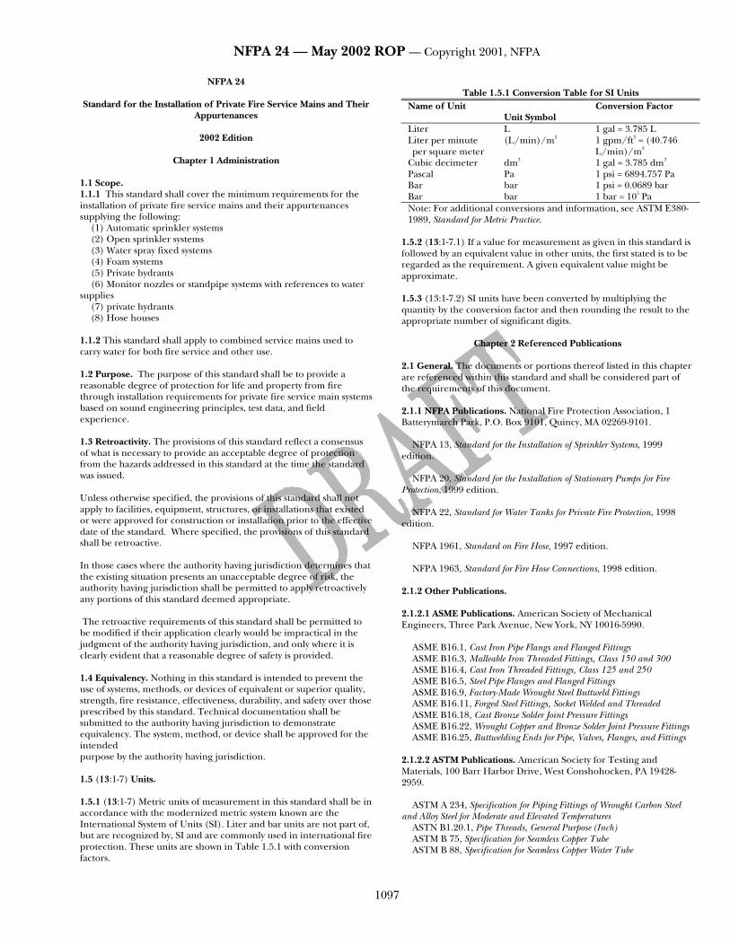
Table 1.5.1 Conversion Table for SI Units
Name of Unit Unit Symbol
Conversion Factor
Liter L 1 gal = 3.785 L Liter per minute per square meter
(L/min)/m2 1 gpm/ft2 = (40.746 L/min)/m2
Cubic decimeter dm3 1 gal = 3.785 dm3 Pascal Pa 1 psi = 6894.757 Pa Bar bar 1 psi = 0.0689 bar Bar bar 1 bar = 105 Pa Note: For additional conversions and information, see ASTM E380-1989, Standard for Metric Practice.
1.5.2 (13:1-7.1) If a value for measurement as given in this standard is followed by an equivalent value in other units, the first stated is to be regarded as the requirement. A given equivalent value might be approximate.
1.5.3 (13:1-7.2) SI units have been converted by multiplying the quantity by the conversion factor and then rounding the result to the appropriate number of significant digits.
Chapter 2 Referenced Publications 2.1 General. The documents or portions thereof listed in this chapter are referenced within this standard and shall be considered part of the requirements of this document. 2.1.1 NFPA Publications. National Fire Protection Association, 1 Batterymarch Park, P.O. Box 9101, Quincy, MA 02269-9101.
NFPA 13, Standard for the Installation of Sprinkler Systems, 1999 edition.
NFPA 20, Standard for the Installation of Stationary Pumps for Fire
Protection, 1999 edition. NFPA 22, Standard for Water Tanks for Private Fire Protection, 1998
edition. NFPA 1961, Standard on Fire Hose, 1997 edition. NFPA 1963, Standard for Fire Hose Connections, 1998 edition.
2.1.2 Other Publications. 2.1.2.1 ASME Publications. American Society of Mechanical Engineers, Three Park Avenue, New York, NY 10016-5990.
ASME B16.1, Cast Iron Pipe Flangs and Flanged Fittings ASME B16.3, Malleable Iron Threaded Fittings, Class 150 and 300 ASME B16.4, Cast Iron Threaded Fittings, Class 125 and 250 ASME B16.5, Steel Pipe Flanges and Flanged Fittings ASME B16.9, Factory-Made Wrought Steel Buttweld Fittings ASME B16.11, Forged Steel Fittings, Socket Welded and Threaded ASME B16.18, Cast Bronze Solder Joint Pressure Fittings ASME B16.22, Wrought Copper and Bronze Solder Joint Pressure Fittings ASME B16.25, Buttwelding Ends for Pipe, Valves, Flanges, and Fittings
2.1.2.2 ASTM Publications. American Society for Testing and Materials, 100 Barr Harbor Drive, West Conshohocken, PA 19428-2959.
ASTM A 234, Specification for Piping Fittings of Wrought Carbon Steel and Alloy Steel for Moderate and Elevated Temperatures
ASTN B1.20.1, Pipe Threads, General Purpose (Inch) ASTM B 75, Specification for Seamless Copper Tube ASTM B 88, Specification for Seamless Copper Water Tube

NFPA 24 — May 2002 ROP — Copyright 2001, NFPA
1098
ASTM B 251, Requirements for Wrought Seamless Copper and Copper-Alloy Tube
ASTM F 437, Chlorinated Polyvinyl Chloride (CPVC) Specification for Schedule 80 CPVC Threaded Fittings
ASTM F 438, Specification for Schedule 40 CPVC Socket-Type Fittings ASTM F 439, Specification for Schedule 80 CPVC Socket-Type Fittings
2.1.2.3 AWS Publication. American Welding Society, 550 N.W. LeJeune Road, Miami, FL 33126.
AWS B2.1, Specification of Welding Procedures and Welders for Piping and Tubing 2.1.2.4 AWWA Publications. American Water Works Association, 6666 West Quincy Avenue, Denver, CO 80235.
AWWA C104, Cement Mortar Lining for Ductile Iron Pipe and Fittings for Water, 1990.
AWWA C105, Polyethylene Encasement for Ductile Iron Piping for Water
and Other Liquids, 1993. AWWA C110, Ductile Iron and Gray Iron Fittings, 3-in. Through 48-in.,
for Water and Other Liquids, 1993. AWWA C111, Rubber-Gasket Joints for Ductile Iron Pressure Pipe and
Fittings, 1990. AWWA C115, Flanged Ductile Iron Pipe with Threaded Flanges, 1988. AWWA C150, Thickness Design of Ductile Iron Pipe, 1991. AWWA C151, Ductile Iron Pipe, Centrifugally Cast in Metal Molds or
Sand-Lined Molds, for Water or Other Liquids, 1991. AWWA C200, Steel Water Pipe 6 in. and Larger, 1991. AWWA C203, Coal-Tar Protective Coatings and Linings for Steel Water
Pipelines Enamel and Tape — Hot Applied, 1991. AWWA C205, Cement-Mortar Protective Lining and Coating for Steel
Water Pipe 4 in. and Larger — Shop Applied, 1989. AWWA C206, Field Welding of Steel Water Pipe, 1991. AWWA C207, Steel Pipe Flanges for Waterworks Service — Sizes 4 in.
Through 144 in., 1986. AWWA C208, Dimensions for Fabricated Steel Water Pipe Fittings, 1983. AWWA C300, Reinforced Concrete Pressure Pipe, Steel-Cylinder Type for
Water and Other Liquids, 1989. AWWA C301, Prestressed Concrete Pressure Pipe, Steel-Cylinder Type, for
Water and Other Liquids, 1992. AWWA C302, Reinforced Concrete Pressure Pipe, Non-Cylinder Type, for
Water and Other Liquids, 1987. AWWA C303, Reinforced Concrete Pressure Pipe, Steel-Cylinder Type,
Pretensioned, for Water and Other Liquids, 1987. AWWA C400, Asbestos-Cement Distribution Pipe, 4 in. Through 16 in.,
for Water and Other Liquids, 1993. AWWA C401, Selection of Asbestos-Cement Water Pipe, 1993. AWWA C600, Installation of Ductile Iron Water Mains and Their
Appurtenances, 1993.
AWWA C602, Cement-Mortar Lining of Water Pipe Lines 4 in. and Larger — in Place, 1989.
AWWA C603, Installation of Asbestos-Cement Pressure Pipe, 1990. AWWA C900, Polyvinyl Chloride (PVC) Pressure Pipe, 4 in. Through 12
in., for Water Distribution, 1989. AWWA M11, Steel Pipe — A Guide for Design and Installation, 1989.
2.1.2.1 ANSI Publication. American National Standards Institute, Inc., 11 West 42nd Street, 13th floor, New York, NY 10036.
ANSI B16.1, Standard for Cast-Iron Pipe Flanges and Flanged Fittings for 25, 125, 250 and 800 lb, 1975.
Chapter 3 Definitions 3.1 General. The definitions contained in this chapter shall apply to the terms used in this standard. Where terms are not included, common usage of the terms shall apply. 3.2 NFPA Official Definitions. 3.2.1* Approved. Acceptable to the authority having jurisdiction. 3.2.2* Authority Having Jurisdiction. The organization, office, or individual responsible for approving equipment, an installation, or a procedure. 3.2.3 Labeled. Equipment or materials to which has been attached a label, symbol, or other identifying mark of an organization that is acceptable to the authority having jurisdiction and concerned with product evaluation, that maintains periodic inspection of production of labeled equipment or materials, and by whose labeling the manufacturer indicates compliance with appropriate standards or performance in a specified manner. 3.2.4* Listed. Equipment, materials, or services included in a list published by an organization that is acceptable to the authority having jurisdiction and concerned with evaluation of products or services, that maintains periodic inspection of production of listed equipment or materials or periodic evaluation of services, and whose listing states that either the equipment, material, or service meets appropriate designated standards or has been tested and found suitable for a specified purpose. 3.2.5 Shall. Indicates a mandatory requirement. 3.2.6 Should. Indicates a recommendation or that which is advised but not required. 3.2.7 Standard. A document, the main text of which contains only mandatory provisions using the word “shall” to indicate requirements and which is in a form generally suitable for mandatory reference by another standard or code or for adoption into law. Nonmandatory provisions shall be located in an appendix, footnote, or fine-print note and are not to be considered a part of the requirements of a standard. 3.3 General Definitions. 3.3.1* (13:1-4.7) Private Fire Service Main. Private fire service main, as used in this standard, is that pipe and its appurtenances on private property(1) between a source of water and the base of the riser for water-based fire protection systems (2) between a source of water and inlets to foam-making systems (3) between a source of water and the base elbow of private hydrants or monitor nozzles, and (4) used as fire pump suction and discharge piping (5) beginning at the inlet side of the check valve on a gravity or pressure tank. [13:1-4.7]

NFPA 24 — May 2002 ROP — Copyright 2001, NFPA
1099
Chapter 4 General Requirements 4.1* Plans. 4.1.1 (13:8-1.1) Working plans shall be submitted for approval to the authority having jurisdiction before any equipment is installed or remodeled. 4.1.2 Deviation from approved plans shall require permission of the authority having jurisdiction. 4.1.3 (13:8-1.1.1) Working plans shall be drawn to an indicated scale on sheets of uniform size, with a plan of each floor, and shall include the following items that pertain to the design of the system:
(1) [24:1-4.2(a)] The size and location of all water supplies (2)[13:8-1.1.1(27)] The size and location of standpipe risers, hose
outlets, hand hose, monitor nozzles, and related equipment (3) [13:8-1.1.1(28)] The following items that pertain to private fire
service mains: a. Size b. Length c. Location d. Weight e. Material f. Point of connection to city main g. Sizes, types, and locations of valves, valve indicators,
regulators, meters, and valve pits h. Depth at which the top of the pipe is laid below grade
(4) [13:8-1.1.1(43)] The following items that pertain to hydrants:
a. Size and location, including size and number of outlets and whether outlets are to be equipped with independent gate valves.
b. Whether hose houses and equipment are to be provided, and by whom
c. Static and residual hydrants used in flow (5) [13:8-1.1.1(44)] Size, location, and piping arrangement of fire
department connections 4.2 (24:1-5) Installation Work. 4.2.1 Installation work shall be performed by fully experienced and responsible persons. 4.2.2 The authority having jurisdiction shall always be consulted before the installation or remodeling of private fire service mains.
Chapter 5 Water Supplies 5.1* (13:9-2.1) Connection to Waterworks Systems. 5.1.1 (13:9-2.1) A connection to a reliable waterworks system shall be an acceptable water supply source. 5.1.2 (13:9-2.1) The volume and pressure of a public water supply shall be determined from waterflow test data. 5.1.3 An adjustment to the waterflow test data to account for the following shall be made, as appropriate:
(1) Daily and seasonal fluctuations (2) Possible interruption by flood or ice conditions (3) Large simultaneous industrial use (4) Future demand on the water supply system (5) Other conditions that could affect the water supply
5.2 (13:9-1.3) Size of Fire Mains.
5.2.1 (13:9-1.3) Private Fire Service Mains. Pipe smaller than 6 in. (152.4 mm) in diameter shall not be installed as a private service main supply hydrants. 5.2.2 (13:9-1.3) Mains Not Supplying Hydrants. For mains that do not supply hydrants, sizes smaller than 6 in. (152.4 mm) shall be permitted to be used subject to the following restrictions:
(1) The main shall supply only the following types of systems: a. Automatic sprinkler systems b. Open sprinkler systems c. Water spray fixed systems d. Foam systems e. Class II standpipe systems
(2) Hydraulic calculations shall show that the main is able to supply the total demand at the appropriate pressure.
(3) Systems that are not hydraulically calculated shall have a main at least as large as the riser. 5.3 Pressure-Regulating Devices and Meters. 5.3.1 (24:2-2.4) No pressure-regulating valve shall be used in the water supply, except by special permission of the authority having jurisdiction. 5.3.2 (13:9-1.7) Where meters are required by other authorities, they shall be listed. 5.4* (13:9-1.8) Connection from Waterworks Systems. 5.4.1 (13:9-1.8) The requirements of the public health authority having jurisdiction shall be determined and followed. 5.4.2 (13:9-1.8) Where equipment is installed to guard against possible contamination of the public water system, such equipment and devices shall be listed for fire protection service. 5.5 (24:2-2.6) Connections to Public Water Systems. Connections to public water systems shall be controlled by post indicator valves of an approved type and installed in accordance with the requirements of Section 6.3. 5.6 (13:9-2.2) Pumps. A single, automatically controlled fire pump installed in accordance with NFPA 20, Standard for the Installation of Stationary Pumps for Fire Protection, shall be an acceptable water supply source. 5.7 (13:9-2.3 & 13:9-2.4) Tanks. Tanks shall be installed in accordance with NFPA 22, Standard for Water Tanks for Private Fire Protection. 5.8 (13:9-2.5) Penstocks, Flumes, Rivers, Lakes, or Reservoirs. Water supply connections from penstocks, flumes, rivers, lakes, or reservoirs shall be arranged to avoid mud and sediment and shall be provided with approved, double, removable screens or approved strainers installed in an approved manner. 5.9* (13:5-15.2) Fire Department Connections. 5.9.1 (13:5-15.2.1) General. A fire department connection shall be provided as described in Section 5.9. 5.9.1.1 (24:2-6.1) Fire department connections shall not be required where approved by the authority having jurisdiction. 5.9.1.2(13:5-15.2.3.7) Fire department connections shall be properly supported. 5.9.1.3 (13:3-9.3) Fire department connections shall be of an approved type.

NFPA 24 — May 2002 ROP — Copyright 2001, NFPA
1100
5.9.1.4 (13:3-9.2) Fire department connections shall be equipped with listed plugs or caps that are secured and arranged for easy removal by fire departments. 5.9.2 (13:3-9.1) Couplings. 5.9.2.1 (13:3-9.1) The fire department connection(s) shall use an NH internal threaded swivel fitting(s) with an NH standard thread(s). 5.9.2.2 At least one of the connections shall be the 2.5-7.5 NH standard thread specified in NFPA 1963, Standard for Fire Hose Connections. 5.9.2.3 (13:3-9.1) Where local fire department connections do not conform to NFPA 1963, the authority having jurisdiction shall designate the connection to be used. 5.9.2.4 (13:3-9.1) The use of threadless couplings shall be permitted where required by the authority having jurisdiction and where listed for such use. 5.9.3 (13:5-15.2.4) Valves. 5.9.3.1 (13:5-15.2.4.1) A listed check valve shall be installed in each fire department connection. 5.9.3.2 (13:5-15.2.4.2) No shutoff valve shall be permitted in the fire department connection piping. 5.9.4 (13:5-15.2.5) Drainage. 5.9.4.1 (13:5-15.2.5) The pipe between the check valve and the outside hose coupling shall be equipped with an approved automatic drip. 5.9.4.2 (13:5-15.2.5) An automatic drip shall not be required in areas not subject to freezing. 5.9.5 (13:5-15.2.3.5) Location and Signage. 5.9.5.1 (13:5-15.2.3.5) Fire department connections shall be located on the street side of buildings. 5.9.5.2 Fire department connections shall be located and arranged so that hose lines can be readily and conveniently attached to the inlets without interference from any nearby objects, including buildings, fences, posts, or other fire department connections. 5.9.5.3 (13:5-15.2.3.5) Each fire department connection to sprinkler systems shall be designated by a sign as follows:
(1) The sign shall have raised or engraved letters at least 1 in. (25.4 mm) in height on a plate or fitting.
(2) The sign shall indicate the service for which the connection is intended and shall read, for example as follows:
AUTOSPKR OPEN SPKR AND STANDPIPE
5.9.5.4 (13:5-15.2.3.5) A sign at inlets shall indicate the pressure required to deliver the greatest system demand. 5.9.5.5 The sign specified in 5.9.5.3 shall not be required where the system demand pressure is less than 150 psi (10.3 bar). 5.9.5.6 (24:2-6.10.2) Where a fire department connection only supplies a portion(s) of the building, a sign shall be attached to indicate the portion(s) of the building supplied.
Chapter 6 Valves 6.1 (13:3-8.1) Types of Valves. 6.1.1 (13:3-8.1) All valves controlling connections to water supplies and to supply pipes to sprinklers shall be listed indicating valves. 6.1.2 (13:3-8.1) Indicating valves shall not close in less than 5 seconds when operated at maximum possible speed from the fully open position. 6.1.3 (13-3-8.1) A listed underground gate valve equipped with a listed indicator post shall be permitted. 6.1.4 (13:3-8.1) A listed water control valve assembly with a reliable position indication connected to a remote supervisory station shall be permitted. 6.1.5 (13:3-8.1) A nonindicating valve, such as an underground gate valve with approved roadway box, complete with T-wrench, and accepted by the authority having jurisdiction, shall be permitted. 6.2 Valves Controlling Water Supplies. 6.2.1 (13:5-14.1.1.2) At least one listed indicating valve shall be installed in each source of water supply. 6.2.2 (13:5-14.1.1.2) No shutoff valve shall be permitted in the fire department connection. 6.2.3 (13:5-14.1.1.5) Where more than one source of water supply exists, a check valve shall be installed in each connection. 6.2.4 (13:5-14.1.1.5) Where cushion tanks are used with automatic fire pumps, a check valve shall not be required in the cushion tank connection. 6.2.5* (13:5-14.1.1.8) In a connection serving as one source of supply, listed indicating valves or post indicator valves shall be installed on both sides of all check valves required in 6.2.3. 6.2.6 (13:5-14.1.1.8) In the discharge pipe from a pressure tank or a gravity tank of less than 15,000 gal (56.78 m3) capacity, a control valve shall not be required to be installed on the tank side of the check valve. 6.2.7* (13:5-14.1.1.9) The following requirements shall apply where a gravity tank is located on a tower in the yard:
(1) The control valve on the tank side of the check valve shall be an outside screw and yoke or a listed indicating valve.
(2) The other control valve shall be either an outside screw and yoke, a listed indicating valve, or a listed valve having a post-type indicator. 6.2.8* The following requirements shall apply where a gravity tank is located on a building:
(1) Both control valves shall be outside screw and yoke or listed indicating valves.
(2) All fittings inside the building, except the drain tee and heater connections, shall be under the control of a listed valve. 6.2.9 (13:5-14.1.1.10) One of the following requirements shall be met where a pump is located in a combustible pump house or exposed to danger from fire or falling walls, or where a tank discharges into a private fire service main fed by another supply:
(1)* The check valve in the connection shall be located in a pit. (2) The control valve shall be of the post indicator type and located
a safe distance outside buildings.

NFPA 24 — May 2002 ROP — Copyright 2001, NFPA
1101
6.2.10* (13:5-14.1.1.11) All control valves shall be located where readily accessible and free of obstructions. 6.3 Post Indicator Valves. 6.3.1* (24:3-3.1) General. Every connection from the private fire service main to a building shall be provided with a listed post indicator valve located to control all sources of water supply. 6.3.2 (24:3-3.1) Alternate Provision for Post Indicator Valves. The authority having jurisdiction shall be permitted to waive the requirement for the post indicator valves required in 6.3.1 where the provisions of Sections 6.1 and 6.4 are met. 6.3.3 Location. 6.3.3.1 (24:3-3.2) Post indicator valves shall be located not less than 40 ft (12.2 m) from buildings. 6.3.3.2 (13:A-5-14.1.3) Where post indicator valves cannot be located in accordance with 6.3.3.1, they shall be permitted to be located closer where approved by the authority having jurisdiction, or wall post indicator valves shall be used, provided they are set in locations near blank walls where the possibility of injury by falling walls is unlikely and from which people are not likely to be driven by smoke or heat. 6.3.4 Arrangement. 6.3.4.1 (13:5-14.1.3.1) Post indicator valves shall be set so that the top of the post is 36 in. (0.9 m) above the final grade. 6.3.4.2 (13:5-14.1.3.2) Post indicator valves shall be protected against mechanical damage where needed. 6.4 Valves in Pits. 6.4.1 (13:5-14.1.4.1) Where it is impractical to provide a post indicator valve, valves shall be permitted to be placed in pits and shall be approved by the authority having jurisdiction. 6.4.2 Valve pits located at or near the base of the riser of an elevated tank shall be designed in accordance with Chapter 9 of NFPA 22, Standard for Water Tanks for Private Fire Protection. 6.4.3* (13:5-14.1.4.2) Where used, valve pits shall be of adequate size and readily accessible for inspection, operation, testing, maintenance, and removal of equipment contained therein. 6.4.4 Valve pits shall be constructed and arranged to properly protect the installed equipment from movement of earth, freezing, and accumulation of water. 6.4.4.1 Depending on soil conditions and the size of the pit, valve pits shall be permitted to be constructed of any of the following materials:
(1) Poured-in-place or precast concrete, with or without reinforcement
(2) Brick (3) Other approved materials
6.4.4.2 Where the water table is low and the soil is porous, crushed stone or gravel shall be permitted to be used for the floor of the pit. 6.4.5 (13:5-14.1.4.3) The location of the valve shall be marked, and the cover of the pit shall be kept free of obstructions. 6.5 Sectional Valves. 6.5.1 (13:5-14.1.5.1) Large, private, fire service main systems shall have sectional controlling valves at appropriate points to permit
sectionalizing the system in the event of a break or for making repairs or extensions. 6.5.2 (13:5-14.1.5.2) A sectional valve shall be provided at the following locations:
(1) On each bank where a main crosses water (2) Outside the building foundation(s) where a main or a section
of a main runs under a building. 6.6 Identifying and Securing Valves. 6.6.1 (13:5-14.1.1.12) Identification signs shall be provided at each valve to indicate its function and what it controls. 6.6.2* (13:5-14.1.1.3) Valves on connections to water supplies, sectional control and isolation valves, and other valves in supply pipes to sprinklers and other fixed water-based fire suppression systems shall be supervised by one of the following methods:
(1) Central station, proprietary, or remote station signaling service (2) Local signaling service that causes the sounding of an audible
signal at a constantly attended location (3) An approved procedure to ensure that valves are locked in the
correct position (4) An approved procedure to ensure that valves are located within
fenced enclosures under the control of the owner, sealed in the open position, and inspected weekly 6.6.3 (13:5-14.1.1.3) Supervision of underground gate valves with roadway boxes shall not be required. 6.7 (13:5-14.1.1.6) Check Valves. Check valves shall be installed in a vertical or horizontal position in accordance with their listing.
Chapter 7 Hydrants 7.1 General. 7.1.1 (14:2-9.1) Hydrants shall be of approved type and have not less than a 6-in. (152-mm) diameter connection with the mains. 7.1.1.1 A valve shall be installed in the hydrant connection. 7.1.1.2 The number, size, and arrangement of outlets; the size of the main valve opening; and the size of the barrel shall be suitable for the protection to be provided and shall be approved by the authority having jurisdiction. 7.1.1.3 Independent gate valves on 2 1/2-in. (64-mm) outlets shall be permitted. 7.1.2* (14:2-9.2) Hydrant outlet threads shall have NHS external threads for the size outlet(s) supplied as specified in NFPA 1963, Standard for Fire Hose Connections. 7.1.3 (14:2-9.2) Where local fire department connections do not conform to NFPA 1963, Standard for Fire Hose Connections, the authority having jurisdiction shall designate the connection to be used. 7.1.4* (14:2-9.3) Hydrants on private service mains shall not be equipped with pumper outlets unless the calculated demand for large hose (3.5 in. and larger) is added to the attack hose and sprinkler system demands when determining the total demand on the fire protection water supply. 7.2 Number and Location. 7.2.1* (14:5-13.1) Hydrants shall be provided and spaced in accordance with the requirements of the authority having jurisdiction.

NFPA 24 — May 2002 ROP — Copyright 2001, NFPA
1102
7.2.2 (14:5-13.1) Public hydrants shall be permitted to be recognized as meeting all or part of the requirements of Section 7.2. 7.2.3* (14:5-13.2) Hydrants shall be located not less than 40 ft (12.2 m) from the buildings to be protected. 7.2.4 (14:5-13.2) Where hydrants cannot be located in accordance with 7.2.3, locations closer than 40 ft (12.2 m) from the building or wall hydrants shall be permitted to be used where approved by the authority having jurisdiction. 7.2.5 (14:5-13.3) Hydrants shall not be installed at less than the equivalent depth of bury from retaining walls where there is danger of frost through the walls. 7.3 Installation and Maintenance. 7.3.1* (14:4-5.1) Hydrants shall be set on flat stones or concrete slabs and shall be provided with small stones (or the equivalent) placed about the drain to ensure drainage. 7.3.2 (14:4-5.2) Where soil is of such a nature that the hydrants will not drain properly with the arrangement specified in 7.3.1, or where groundwater stands at levels above that of the drain, the hydrant drain shall be plugged at the time of installation. 7.3.2.1 If the drain is plugged, hydrants in service in cold climates shall be pumped out after usage. 7.3.2.2 Such hydrants shall be marked to indicate the need for pumping out after usage. 7.3.3* (14:4-5.3) The center of a hose outlet shall be not less than 18 in. (457 mm) above final grade or, where located in a hose house, 12 in. (305 mm) above the floor. 7.3.4 (14:4-5.4) Hydrants shall be fastened to piping and anchored in accordance with the requirements of NFPA 13, Standard for the Installation of Sprinkler Systems. 7.3.5 (14:4-5.5) Hydrants shall be protected if subject to mechanical damage. 7.3.6 The means of hydrant protection shall be arranged in a manner that does not interfere with the connection to, or operation of, hydrants. 7.3.7 (14:4-5.6) The following shall not be installed in the service stub between a fire hydrant and private water supply piping:
(1) Check valves (2) Detector check valves (3) Backflow prevention valves (4) Other similar appurtenances
7.3.8* (24:4-3.6) To ensure proper functioning, wet barrel hydrants shall be tested at least annually, and dry barrel hydrants tested semiannually in the early spring and fall, in accordance with the requirements of the authority having jurisdiction.
Chapter 8 Hose Houses and Equipment 8.1 General. 8.1.1* (14:2-6.2.1) A supply of hose and equipment shall be provided where hydrants are intended for use by plant personnel or a fire brigade. 8.1.1.1 The quantity and type of hose and equipment shall depend on the following:
(1) Number and location of hydrants relative to the protected property (2) Extent of the hazard (3) Fire-fighting capabilities of potential users 8.1.1.2 The authority having jurisdiction shall be consulted regarding quantity and type of hose. 8.1.2 (14:2-6.2.2) Hose shall be stored so it is readily accessible and is protected from the weather by storing in hose houses or by placing hose reels or hose carriers in weatherproof enclosures. 8.1.3* (24:5-1.2) Hose shall conform to NFPA 1961, Standard on Fire Hose. 8.1.4 (14:2-7) Hose Connections. 8.1.4.1 Hose connections shall have external National Hose Standard (NHS) threads, for the valve size specified, in accordance with NFPA 1963, Standard for Fire Hose Connections. 8.1.4.2 Hose connections shall be equipped with caps to protect the hose threads. 8.1.4.3 (14:2-7) Where local fire department hose threads do not conform to NFPA 1963, Standard for Fire Hose Connections, the authority having jurisdiction shall designate the hose threads to be used. 8.2 Location. 8.2.1 (14:5-14.1) Where hose houses are utilized, they shall be located over or immediately adjacent to the hydrant. 8.2.2 Hydrants within hose houses shall be as close to the front of the house as possible and still allow sufficient room back of the doors for the hose gates and the attached hose. 8.2.3 (14:5-14.2) Where hose reels or hose carriers are utilized, they shall be located so that the hose can be brought into use at a hydrant. 8.3 (14:2-6.2.3) Construction. 8.3.1 Hose houses shall be of substantial construction on foundations. 8.3.2 The construction shall protect the hose from weather and vermin, and shall be designed so that hose lines can be brought into use. 8.3.3 Clearance shall be provided for operation of the hydrant wrench. 8.3.4 Ventilation shall be provided. 8.3.5 The exterior shall be painted or otherwise protected against deterioration. 8.4* (14:2-6.2.4) Size and Arrangement. Hose houses shall be of a size and arrangement that provide shelves or racks for the hose and equipment. 8.5 (14:2-6.2.5) Marking. Hose houses shall be plainly identified. 8.6 (14:2-6.2.6) General Equipment. 8.6.1* (14:2-6.2.6.1) Where hose houses are used in addition to the hose, each shall be equipped with the following:
(1) Two approved adjustable spray–solid stream nozzles equipped with shutoffs for each size of hose provided
(2) One hydrant wrench (in addition to wrench on hydrant)

NFPA 24 — May 2002 ROP — Copyright 2001, NFPA
1103
(3) Four coupling spanners for each size hose provided (4) Two hose coupling gaskets for each size hose
8.6.2 (14:2-6.2.6.2) Where two sizes of hose and nozzles are provided, reducers or gated wyes shall be included in the hose house equipment. 8.7 (14:2-6.2.7) Domestic Service Use Prohibited. The use of hydrants and hose for purposes other than fire-related services shall be prohibited.
Chapter 9 Master Streams 9.1* (14:5-15 & 14:5-15.1) Master Streams. Master streams shall be delivered by monitor nozzles, hydrant-mounted monitor nozzles, and similar master stream equipment capable of delivering more than 250 gpm (946 L/min). 9.2 (14:5-15.2) Application and Special Considerations. Master streams shall be provided as protection for the following:
(1) Large amounts of combustible materials located in yards (2) Average amounts of combustible materials in inaccessible
locations (3) Occupancies presenting special hazards as required by the
authority having jurisdiction
Chapter 10 Underground Piping 10.1* Piping Materials. 10.1.1* Listing. Piping shall be listed for fire protection service or shall comply with the standards in Table 10.1.1.
Table 10.1.1 Manufacturing Standards for Underground Pipe Materials and Dimensions Standard
Ductile Iron Cement Mortar Lining for Ductile AWWA C104
Iron Pipe and Fittings for Water Polyethylene Encasement for Ductile AWWA C105
Iron Piping for Water and Other Liquids Ductile Iron and Gray Iron Fittings, AWWA C110
3-in. Through 48-in., for Water and Other Liquids
Rubber-Gasket Joints for Ductile AWWA C111
Iron Pressure Pipe and Fittings Flanged Ductile Iron Pipe with AWWA C115
Threaded Flanges Thickness Design of Ductile Iron Pipe AWWA C150 Ductile Iron Pipe, Centrifugally Cast for AWWA C151
Water Installation of Ductile Iron Water AWWA C600
Mains and Their Appurtenances Steel Steel Water Pipe 6 in. and Larger AWWA C200 Coal-Tar Protective Coatings and AWWA C203
Linings for Steel Water Pipelines Enamel and Tape — Hot Applied
Table 10.1.1 Manufacturing Standards for Underground Pipe
(continued) Materials and Dimensions Standard Cement-Mortar Protective Lining AWWA C205
and Coating for Steel Water Pipe 4 in. and Larger — Shop Applied
Field Welding of Steel Water Pipe AWWA C206 Steel Pipe Flanges for Waterworks AWWA C207 Service — Sizes 4 in. Through 144 in Dimensions for Fabricated Steel AWWA C208
Water Pipe Fittings Steel Pipe — A Guide for Design AWWA M11
and Installation Concrete Reinforced Concrete Pressure Pipe, AWWA C300
Steel-Cylinder Type for Water and Other Liquids
Prestressed Concrete Pressure Pipe, AWWA C301
Steel-Cylinder Type, for Water and Other Liquids
Reinforced Concrete Pressure Pipe, AWWA C302
Non-Cylinder Type, for Water and Other Liquids
Reinforced Concrete Pressure Pipe, AWWA C303
Steel-Cylinder Type, Pretensioned, for Water and Other Liquids
Asbestos-Cement Distribution Pipe, AWWA C400
4 in. Through 16 in., for Water and Other Liquids
Selection of Asbestos-Cement Water Pipe AWWA C401 Cement-Mortar Lining of Water Pipe AWWA C602
Lines 4 in. and Larger — in Place Installation of Asbestos-Cement Pressure Pipe AWWA C603 Plastic Polyvinyl Chloride (PVC) Pressure AWWA C900
Pipe, 4 in. Through 12 in., for Water Distribution
Copper Specification for Seamless Copper Tube ASTM B 75 Specification for Seamless Copper Water Tube ASTM B 88 Requirements for Wrought Seamless Copper ASTM B 251
and Copper-Alloy Tube __________________________________________________________
10.1.2 Steel Pipe. Steel piping shall not be used for general underground service, unless specifically listed for such service. 10.1.3 Steel Pipe Used with Fire Department Connections. Where externally coated and wrapped and internally galvanized, steel pipe shall be permitted to be used between the check valve and the outside hose coupling for the fire department connection.
NFPA 24 — May 2002 ROP — Copyright 2001, NFPA
1104
10.1.4* Pipe Type and Class. The type and class of pipe for a particular underground installation shall be determined through consideration of the following factors:
(1) Fire resistance of the pipe (2) Maximum system working pressure (3) Depth at which the pipe is to be installed (4) Soil conditions (5) Corrosion (6) Susceptibility of pipe to other external loads, including earth
loads, installation beneath buildings, and traffic or vehicle loads 10.1.5 Working Pressure. Pipe shall be designed to withstand a system working pressure of not less than 150 psi (10.3 bar). 10.1.6* Lining of Buried Pipe. All ferrous metal pipe shall be lined in accordance with the applicable standards in Table 10.1.1. 10.2 Fittings. 10.2.1 Standard Fittings. Fittings shall meet the standards in Table 10.2.1 or shall be in accordance with 10.2.3.
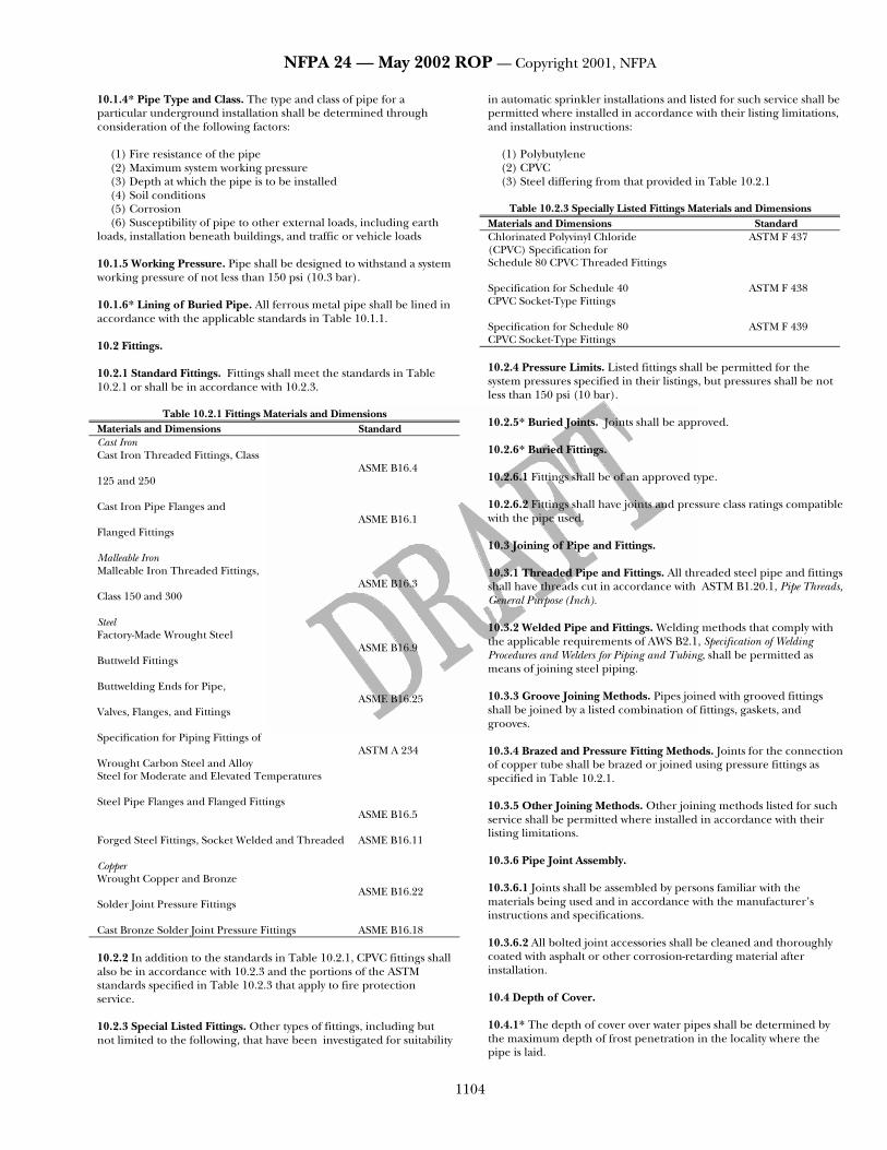
Table 10.2.1 Fittings Materials and Dimensions Materials and Dimensions Standard Cast Iron Cast Iron Threaded Fittings, Class ASME B16.4 125 and 250 Cast Iron Pipe Flanges and ASME B16.1 Flanged Fittings Malleable Iron Malleable Iron Threaded Fittings, ASME B16.3 Class 150 and 300 Steel Factory-Made Wrought Steel ASME B16.9 Buttweld Fittings Buttwelding Ends for Pipe, ASME B16.25 Valves, Flanges, and Fittings Specification for Piping Fittings of ASTM A 234 Wrought Carbon Steel and Alloy Steel for Moderate and Elevated Temperatures Steel Pipe Flanges and Flanged Fittings ASME B16.5 Forged Steel Fittings, Socket Welded and Threaded ASME B16.11 Copper Wrought Copper and Bronze ASME B16.22 Solder Joint Pressure Fittings Cast Bronze Solder Joint Pressure Fittings ASME B16.18 10.2.2 In addition to the standards in Table 10.2.1, CPVC fittings shall also be in accordance with 10.2.3 and the portions of the ASTM standards specified in Table 10.2.3 that apply to fire protection service. 10.2.3 Special Listed Fittings. Other types of fittings, including but not limited to the following, that have been investigated for suitability
in automatic sprinkler installations and listed for such service shall be permitted where installed in accordance with their listing limitations, and installation instructions:
(1) Polybutylene (2) CPVC (3) Steel differing from that provided in Table 10.2.1
Table 10.2.3 Specially Listed Fittings Materials and Dimensions
Materials and Dimensions Standard Chlorinated Polyvinyl Chloride ASTM F 437 (CPVC) Specification for Schedule 80 CPVC Threaded Fittings Specification for Schedule 40 ASTM F 438 CPVC Socket-Type Fittings Specification for Schedule 80 ASTM F 439 CPVC Socket-Type Fittings 10.2.4 Pressure Limits. Listed fittings shall be permitted for the system pressures specified in their listings, but pressures shall be not less than 150 psi (10 bar). 10.2.5* Buried Joints. Joints shall be approved. 10.2.6* Buried Fittings. 10.2.6.1 Fittings shall be of an approved type. 10.2.6.2 Fittings shall have joints and pressure class ratings compatible with the pipe used. 10.3 Joining of Pipe and Fittings. 10.3.1 Threaded Pipe and Fittings. All threaded steel pipe and fittings shall have threads cut in accordance with ASTM B1.20.1, Pipe Threads, General Purpose (Inch). 10.3.2 Welded Pipe and Fittings. Welding methods that comply with the applicable requirements of AWS B2.1, Specification of Welding Procedures and Welders for Piping and Tubing, shall be permitted as means of joining steel piping. 10.3.3 Groove Joining Methods. Pipes joined with grooved fittings shall be joined by a listed combination of fittings, gaskets, and grooves. 10.3.4 Brazed and Pressure Fitting Methods. Joints for the connection of copper tube shall be brazed or joined using pressure fittings as specified in Table 10.2.1. 10.3.5 Other Joining Methods. Other joining methods listed for such service shall be permitted where installed in accordance with their listing limitations. 10.3.6 Pipe Joint Assembly. 10.3.6.1 Joints shall be assembled by persons familiar with the materials being used and in accordance with the manufacturer’s instructions and specifications. 10.3.6.2 All bolted joint accessories shall be cleaned and thoroughly coated with asphalt or other corrosion-retarding material after installation. 10.4 Depth of Cover. 10.4.1* The depth of cover over water pipes shall be determined by the maximum depth of frost penetration in the locality where the pipe is laid.

NFPA 24 — May 2002 ROP — Copyright 2001, NFPA
1105
10.4.2 The top of the pipe shall be buried not less than 1 ft (0.3 m) below the frost line for the locality. 10.4.3 In locations where frost is not a factor, the depth of cover shall be not less than 2 1/2 ft (0.8 m) to prevent mechanical damage. 10.4.4 Pipe under driveways shall be buried at a minimum depth of 3 ft (0.9 m). 10.4.5 Pipe under railroad tracks shall be buried at a minimum depth of 4 ft (1.2 m). 10.4.6 The depth of cover shall be measured from the top of the pipe to finished grade, and due consideration shall always be given to future or final grade and nature of soil. 10.5 Protection Against Freezing. 10.5.1 Where it is impracticable to bury pipe, pipe shall be permitted to be laid aboveground, provided that the pipe is protected against freezing and mechanical damage. 10.5.2 Pipe shall be buried below the frost line where entering streams and other bodies of water. 10.5.3 Where pipe is laid in water raceways or shallow streams, care shall be taken that there will be sufficient depth of running water between the pipe and the frost line during all seasons of frost; a safer method is to bury the pipe 1 ft (0.3048 m) or more under the bed of the waterway. 10.5.4 Pipe shall be located at a distance from stream banks and embankment walls that prevents danger of freezing through the side of the bank. 10.6 Protection Against Damage. 10.6.1 Pipe shall not be run under buildings. 10.6.2 Where pipe must be run under buildings, special precautions shall be taken, including the following:
(1) Arching the foundation walls over the pipe (2) Running pipe in covered trenches (3) Providing valves to isolate sections of pipe under buildings
10.6.3 Fire service mains shall be permitted to enter the building adjacent to the foundation. 10.6.4 Where adjacent structures or physical conditions make it impractical to locate risers immediately inside an exterior wall, such risers shall be permitted to be located as close as practical to exterior walls to minimize underground piping under the building. 10.6.5 Where a riser is located close a to building foundation, underground fittings of the appropriate design and type shall be used to avoid locating pipe joints in or under the foundations. 10.6.6 Mains shall be subjected to an evaluation of the following specific loading conditions and protected, if necessary:
(1) Mains running under railroads carrying heavy cargo (2) Mains running under large piles of heavy commodities (3) Mains located in areas that subject the main to heavy shock and
vibrations 10.6.7* Where it is necessary to join metal pipe with pipe of dissimilar metal, the joint shall be insulated against the passage of an electric current using an approved method.
10.6.8 In no case shall pipe specified in 10.6.7 be used for grounding of electrical services. 10.7 Requirement for Laying Pipe. 10.7.1 Pipes, valves, hydrants, and fittings shall be inspected for damage when received and shall be inspected prior to installation. 10.7.2 The torquing of bolted joints shall be checked. 10.7.3 Pipe, valves, hydrants, and fittings shall be clean inside. 10.7.4 When work is stopped, the open ends of pipe, valves, hydrants, and fittings shall be plugged to prevent stones and foreign materials from entering. 10.7.5 All pipe, fittings, valves, and hydrants shall be carefully lowered into the trench using appropriate equipment and carefully examined for cracks or other defects while suspended above the trench. 10.7.6 Plain ends shall be inspected for signs of damage prior to installation. 10.7.7 Under no circumstances shall water main materials be dropped or dumped. 10.7.8 Pipe shall not be rolled or skidded against other pipe materials. 10.7.9 Pipes shall bear throughout their full length and shall not be supported by the bell ends only or by blocks. 10.7.10 If the ground is soft or of a quicksand nature, special provisions shall be made for supporting pipe. 10.7.11 Valves and fittings used with nonmetallic pipe shall be supported and restrained in accordance with the manufacturer’s specifications. 10.8 Joint Restraint 10.8.1 General. 10.8.1.1* All tees, plugs, caps, bends, reducers, valves, and hydrant branches shall be restrained against movement by using thrust blocks in accordance with 10.8.2 or restrained joint systems in accordance with 10.8.3. 10.8.1.2 Piping with fused, threaded, grooved or welded joints shall not require additional restraining, provided that such joints can pass the hydrostatic test of 10.10.2.2 without shifting of piping or leakage in excess of permitted amounts. 10.8.1.3 On steep grades, mains shall be additionally restrained to prevent slipping. 10.8.1.3.1 Pipe shall be restrained at the bottom of a hill and at any turns (lateral or vertical). 10.8.1.3.2 The restraint specified in 10.8.1.3.1 shall be to natural rock or to suitable piers built on the downhill side of the bell. 10.8.1.3.3 Bell ends shall be installed facing uphill. 10.8.1.3.4 Straight runs on hills shall be restrained as determined by the design engineer. 10.8.2* Thrust Blocks.
NFPA 24 — May 2002 ROP — Copyright 2001, NFPA
1106
10.8.2.1 Thrust blocks shall be considered satisfactory where soil is suitable for their use. 10.8.2.2 Thrust blocks shall be of a concrete mix not leaner than one part cement, two and one-half parts sand, and five parts stone. 10.8.2.3 Thrust blocks shall be placed between undisturbed earth and the fitting to be restrained and shall be capable of such bearing to ensure adequate resistance to the thrust to be encountered. 10.8.2.4 Wherever possible, thrust blocks shall be placed so that the joints are accessible for repair. 10.8.3 Restrained Joint Systems. Fire mains utilizing restrained joint systems shall include the following:
(1) Locking mechanical or push-on joints (2) Mechanical joints utilizing setscrew retainer glands (3) Bolted flange joints (4) Heat-fused or welded joints (5) Pipe clamps and tie rods (6) Other approved methods or devices
10.8.3.1 Sizing Clamps, Rods, Bolts, and Washers. 10.8.3.1.1 Clamps. 10.8.3.1.1.1 Clamps shall have the following dimensions:
(1) 1/2 in. × 2 in. (12.7 mm × 50.8 mm) for pipe 4 in. to 6 in. (2) 5/8 in. × 2 1/2 in. (15.9 mm × 63.5 mm) for pipe 8 in. to 10 in. (3) 5/8 in. × 3 in. (15.9 mm × 76.2 mm) for 12-in. pipe
10.8.3.1.1.2 The diameter of a bolt hole shall be 1/16 in. (1.6 mm) larger than that of the corresponding bolt. 10.8.3.1.2 Rods. 10.8.3.1.2.1 Rods shall be not less than 5/8 in. (15.9 mm) in diameter. 10.8.3.1.2.2 Table 10.8.3.1.2.2 provides the numbers of various diameter rods that shall be used for a given pipe size.
Table 10.8.3.1.2.2 Rod Number — Diameter Combinations (NFPA 13 1999 - Table 6-3.3.1.2, no change)
10.8.3.1.2.3 Where using bolting rods, the diameter of mechanical joint bolts shall limit the diameter of rods to 3/4 in. (19.1 mm). 10.8.3.1.2.4 Threaded sections of rods shall not be formed or bent. 10.8.3.1.2.5 Where using clamps, rods shall be used in pairs for each clamp. 10.8.3.1.2.6 Assemblies in which a restraint is made by means of two clamps canted on the barrel of the pipe shall be permitted to use one rod per clamp if approved for the specific installation by the authority having jurisdiction. 10.8.3.1.2.7 Where using combinations of rods in numbers greater than two, the rods shall be symmetrically spaced. 10.8.3.1.3 Clamp Bolts. Clamp bolts shall have the following diameters:
(1) 5/8 in. (15.9 mm) for pipe 4 in., 6 in., and 8 in. (2) 3/4 in. (19.1 mm) for pipe 10 in. (3) 7/8 in. (22.2 mm) for 12-in. pipe
10.8.3.1.4 Washers. 10.8.3.1.4.1 Washers shall be permitted to be cast iron or steel and round or square. 10.8.3.1.4.2 Cast-iron washers shall have the following dimensions:
(1) 5/8 in. × 3 in. (15.9 mm × 76.2 mm) for pipe 4-in., 6-in., 8-in., and 10-in. pipe
(2) 3/4 in. × 3 1/2 in. (19.1 mm × 88.9 mm) for 12-in. pipe 10.8.3.1.4.3 Steel washers shall have the following dimensions:
(1) 1/2 in. × 3 in. (12.7 mm × 76.2 mm) for 4-in., 6-in., 8-in., and 10-in. pipe
(2) 1/2 in. × 3 1/2 in. (12.7 mm × 88.9 mm) for 12-in. pipe 10.8.3.1.4.4 The diameter of holes shall be 1/8 in. (3.2 mm) larger than that of rods. 10.8.3.2 Sizes of Restraint Straps for Tees. 10.8.3.2.1 Restraint straps for tees shall have the following dimensions:
(1) 5/8 in. (15.9 mm) thick and 2 1/2 in. (63.5 mm) wide for 4-in., 6-in., 8-in., and 10-in. pipe
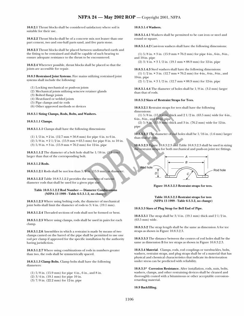
(2) 5/8 in. (15.9 mm) thick and 3 in. (76.2 mm) wide for 12-in. pipe 10.8.3.2.2 The diameter of rod holes shall be 1/16 in. (1.6 mm) larger than that of rods. 10.8.3.2.3 Figure 10.8.3.2.3 and Table 10.8.3.2.3 shall be used in sizing the restraint straps for both mechanical and push-on joint tee fittings.
Rod hole
A
B
CDRod hole
Figure 10.8.3.2.3 Restraint straps for tees.
Table 10.8.3.2.3 Restraint straps for tees (NFPA 13 1999 - Table 6-3.3.2, no change)
10.8.3.3 Sizes of Plug Strap for Bell End of Pipe. 10.8.3.3.1 The strap shall be 3/4 in. (19.1 mm) thick and 2 1/2 in. (63.5 mm) wide. 10.8.3.3.2 The strap length shall be the same as dimension A for tee straps as shown in Figure 10.8.3.2.3. 10.8.3.3.3 The distance between the centers of rod holes shall be the same as dimension B for tee straps as shown in Figure 10.8.3.2.3. 10.8.3.4 Material. Clamps, rods, rod couplings or turnbuckles, bolts, washers, restraint straps, and plug straps shall be of a material that has physical and chemical characteristics that indicate its deterioration under stress can be predicted with reliability. 10.8.3.5* Corrosion Resistance. After installation, rods, nuts, bolts, washers, clamps, and other restraining devices shall be cleaned and thoroughly coated with a bituminous or other acceptable corrosion-retarding material. 10.9 Backfilling.

NFPA 24 — May 2002 ROP — Copyright 2001, NFPA
1107
10.9.1 Backfill shall be tamped in layers or puddled under and around pipes to prevent settlement or lateral movement. 10.9.2 Backfill shall contain no ashes, cinders, refuse, organic matter, or other corrosive materials. 10.9.2 Rocks shall not be placed in trenches. 10.9.3 Frozen earth shall not be used for backfilling. 10.9.4 In trenches cut through rock, tamped backfill shall be used for at least 6 in. (150 mm) under and around the pipe and for at least 2 ft (0.6 m) above the pipe. 10.10 Testing and Acceptance. 10.10.1 Approval of Underground Piping. The installing contractor shall be responsible for the following:
(1) Notifying the authority having jurisdiction and owner’s representative of the time and date testing is to be performed
(2) Performing all required acceptance tests (3) Completing and signing the contractor’s material and test
certificate(s) shown in Figure 10.10.1. 10.10.2 Acceptance Requirements. 10.10.2.1 Flushing of Piping. 10.10.2.1.1 Underground piping, from the water supply to the system riser, and lead-in connections to the system riser shall be completely flushed before connection is made to downstream fire protection system piping. 10.10.2.1.2 The flushing operation shall be continued for a sufficient time to ensure thorough cleaning. 10.10.2.1.3 The minimum rate of flow shall be not less than one of the following:
(1) Hydraulically calculated water demand flow rate of the system, including any hose requirements
(2) Flow necessary to provide a velocity of 10 ft/s (3.1 m/s) in accordance with Table 10.10.2.1.3
(3) Maximum flow rate available to the system under fire conditions
Table 10.10.2.1.3 Flow Required to Produce a Velocity of 10 ft/s (3 m/s) in Pipes.
[NFPA 13 1999 - Table 10-2.1(2), no change] 10.10.2.2 Hydrostatic Test. 10.10.2.2.1 All piping and attached appurtenances subjected to system working pressure shall be hydrostatically tested at 200 psi (13.8 bar) or 50 psi (3.5 bar) in excess of the system working pressure, whichever is greater, and shall maintain that pressure without loss for 2 hours. 10.10.2.2.2 Pressure loss shall be determined by a drop in gauge pressure or visual leakage. 10.10.2.2.3 The test pressure shall be read from a gauge located at the low elevation point of the system or portion being tested. 10.10.2.2.4 The permitted amount of underground piping leakage shall be as follows:
(1)* The amount of leakage at the joints shall not exceed 2 qt/hr (1.89 L/hr) per 100 gaskets or joints, irrespective of pipe diameter.
(2)* The amount of leakage specified in 10.10.2.2.4(1) shall be permitted to be increased by 1 fl oz (30 ml) per inch valve diameter per hour for each metal-seated valve isolating the test section.
(3) If dry barrel hydrants are tested with the main valve open so the hydrants are under pressure, an additional 5 fl oz/min (150 ml/min) of leakage shall be permitted for each hydrant. 10.10.2.2.5 The amount of leakage in buried piping shall be measured at the specified test pressure by pumping from a calibrated container.
Chapter 11 Hydraulic Calculations 11.1 (13:8-4.2.1) General. Pipe friction losses shall be determined based on the Hazen-Williams formula, as follows:
874851
851524..
.
dC
Q.p =
where:
p = frictional resistance (psi/ft of pipe) Q = flow (gpm) C = friction loss coefficient d = actual internal diameter of pipe (in.) For SI units, the following equation shall be used:
5
87.485.1
85.1
1005.6
=
m
mm
dC
Qp
where:
pm = frictional resistance (bar/m of pipe) Qm= flow (L/min) C = friction loss coefficient dm = actual internal diameter (mm)
Chapter 12 Aboveground Pipe and Fittings
12.1 (24:7-5.1) General. Aboveground pipe and fittings shall comply with the applicable sections of Chapters 3 and 5 of NFPA 13, Standard for the Installation of Sprinkler Systems, that address pipe, fittings, joining methods, hangers, and installation. 12.2 Protection of Piping. 12.2.1 (13:5-14.3.3) Aboveground piping for private fire service mains shall not pass through hazardous areas and shall be located so that it is protected from mechanical and fire damage. 12.2.2 (13:5-14.3.3) Aboveground piping shall be permitted to be located in hazardous areas protected by an automatic sprinkler system. 12.2.3 (13:5-14.3.1.2) Where aboveground water-filled supply pipes, risers, system risers, or feed mains pass through open areas, cold rooms, passageways, or other areas exposed to freezing temperatures, the pipe shall be protected against freezing by the following:
(1) Insulating coverings (2) Frostproof casings (3) Other reliable means capable of maintaining a minimum
temperature between 40°F and 120°F (4°C and 48.9°C)

NFPA 24 — May 2002 ROP — Copyright 2001, NFPA
1108
Contractor’s Material and Test Certificate for Underground Piping
Location
PROCEDUREUpon completion of work, inspection and tests shall be made by the contractor’s representative and witnessed by an owner’s representative.All defects shall be corrected and system left in service before contractor’s personnel finally leave the job.
A certificate shall be filled out and signed by both representatives. Copies shall be prepared for approving authorities, owners, andcontractor. It is understood the owner’s representative’s signature in no way prejudices any claim against contractor for faulty material, poorworkmanship, or failure to comply with approving authority’s requirements or local ordinances.
Property name
Property address
Date
Plans
Accepted by approving authorities (names)
Address
Installation conforms to accepted plans
Equipment used is approvedIf no, state deviations
Yes No
Yes No
Has person in charge of fire equipment been instructed as to locationof control valves and care and maintenance of this new equipment?If no, explain
Yes No
Have copies of appropriate instructions and care and maintenancecharts been left on premises?If no, explain
Yes No
Supplies buildings
Undergroundpipes and
joints
Pipe types and class Type joint
Pipe conforms toFittings conforms toIf no, explain
standardstandard
Yes No
Yes No
Joints needed anchorage clamped, strapped, or blocked inaccordance withIf no, explain
standardYes No
Testdescription
Flushing: Flow the required rate until water is clear as indicated by no collection of foreign material in burlap bags atoutlets such as hydrants and blow-offs. Flush at flows not less than 390 gpm (1476 L/min) for 4-in. pipe, 880 gpm(3331 L/min) for 6-in. pipe, 1560 gpm (5905 L/min) for 8-in. pipe, 2440 gpm (9235 L/min) for 10-in. pipe, and 3520 gpm(13,323 L/min) for 12-in. pipe. When supply cannot produce stipulated flow rates, obtain maximum available.Hydrostatic: Hydrostatic tests shall be made at not less than 200 psi (13.8 bar) for 2 hours or 50 psi (3.4 bar) abovestatic pressure in excess of 150 psi (10.3 bar) for 2 hours.Leakage: New pipe laid with rubber gasketed joints shall, if the workmanship is satisfactory, have little or no leakage atthe joints. The amount of leakage at the joints shall not exceed 2 quarts per hour (1.89 L/hr) per 100 joints irrespectiveof pipe diameter. The leakage shall be distributed over all joints. If such leakage occurs at a few joints, the installationshall be considered unsatisfactory and necessary repairs made. The amount of allowable leakage specified above canbe increased by 1 fluid ounce per inch valve diameter per hr. (30 mL/25 mm/hr) for each metal seated valve isolating thetest section. If dry barrel hydrants are tested with the main valve open so the hydrants are under pressure, an additional5 ounces per minute (150 mL/min) leakage is permitted for each hydrant.
New underground piping flushed according to Yes Nostandard by (company)
If no, explain
How flushing flow was obtained Through what type opening
Public water Tank or reservoir Fire pump Hydrant butt Open pipeFlushingtests
Lead-ins flushed according to Yes Nostandard by (company)If no, explain
How flushing flow was obtained Through what type opening
Public water Tank or reservoir Fire pump Y connection to flangeand spigot
Open pipe
Instructions
Figure 10.10.1 – Contractor’s material and test certificate for underground piping.

NFPA 24 — May 2002 ROP — Copyright 2001, NFPA
1109
12.2.4 (13:5-14.3.2.3) Where corrosive conditions exist or piping is exposed to the weather, corrosion-resistant types of pipe, fittings, and hangers or protective corrosion-resistant coatings shall be used. 12.2.5 (24:7-5.2.4) To minimize or prevent pipe breakage where subject to earthquakes, aboveground pipe shall be protected in accordance with the seismic requirements of NFPA 13, Standard for the Installation of Sprinkler Systems. 12.2.6 (24:7-5.2.5) Mains that pass through walls, floors, and ceilings shall be provided with clearances in accordance with NFPA 13, Standard for the Installation of Sprinkler Systems.
Chapter 13 Sizes of Aboveground and Buried Pipe 13.1 (13:9-1.3) Private Service Mains. Pipe smaller than 6 in. (152 mm) in diameter shall not be installed as a private service main supplying hydrants.
13.2 (13:9-1.3) Mains Not Supplying Hydrants. For mains that do not supply hydrants, sizes smaller than 6 in. (152 mm) shall be permitted to be used subject to the following restrictions:
(1) The main shall supply only the following types of systems: a. Automatic sprinkler systems b. Open sprinkler systems c. Water spray fixed systems d. Foam systems e. Class II standpipe systems
(2) Hydraulic calculations shall show that the main is able to supply the total demand at the appropriate pressure.
(3) Systems that are not hydraulically calculated shall have a main at least as large as the riser. 13.3 (24:7-6.2) Mains Supplying Fire Protection Systems. The size of private fire service mains supplying fire protection systems shall be approved by the authority having jurisdiction, and the following factors shall be considered:
(1) Construction and occupancy of the plant
Hydrostatictest
All new underground piping hydrostatically tested at Joints covered
Yes Nopsi for hours
Leakagetest
Total amount of leakage measured
gallons hours
Allowable leakage
gallons hours
HydrantsNumber installed Type and make All operate satisfactorily
Yes No
Controlvalves
Water control valves left wide openIf no, state reason
Yes No
Hose threads of fire department connections and hydrants interchangeable withthose of fire department answering alarm
Yes No
Remarks
Date left in service
Signatures
Name of installing contractor
Tests witnessed by
For property owner (signed) Title Date
For installing contractor (signed) Title Date
Additional explanation and notes
Figure 10.1.1 Contractor’s Material and Test Certificate for Underground Piping. (continued)

NFPA 24 — May 2002 ROP — Copyright 2001, NFPA
1110
(2) Fire flow and pressure of the water required (3) Adequacy of the water supply
Chapter 14 Operating Test
14.1 Hydrant Test Procedure.(13:10-2.4.5.1) 14.1.1 Each hydrant shall be fully opened and closed under system water pressure. 14.1.2 Dry barrel hydrants shall be checked for proper drainage. 14.1.3 Where fire pumps are available, the tests required in 14.1.1 and 14.1.2 shall be completed with the pumps running. 14.2 Control Valves Test Procedures.(13:10-2.4.5.2) All control valves shall be fully closed and opened under system water pressure to ensure proper operation.
Annex A Annex A is not a part of the requirements of this NFPA document but is included for informational purposes only. This annex contains explanatory material, numbered to correspond with the applicable text paragraphs. A.3.2.1 Approved. The National Fire Protection Association does not approve, inspect, or certify any installations, procedures, equipment, or materials; nor does it approve or evaluate testing laboratories. In determining the acceptability of installations, procedures, equipment, or materials, the authority having jurisdiction may base acceptance on compliance with NFPA or other appropriate standards. In the absence of such standards, said authority may require evidence of proper installation, procedure, or use. The authority having jurisdiction may also refer to the listings or labeling practices of an organization that is concerned with product evaluations and is thus in a position to determine compliance with appropriate standards for the current production of listed items. A.3.2.2 Authority Having Jurisdiction. The phrase “authority having jurisdiction” is used in NFPA documents in a broad manner, since jurisdictions and approval agencies vary, as do their responsibilities. Where public safety is primary, the authority having jurisdiction may be a federal, state, local, or other regional department or individual such as a fire chief; fire marshal; chief of a fire prevention bureau, labor department, or health department; building official; electrical inspector; or others having statutory authority. For insurance purposes, an insurance inspection department, rating bureau, or other insurance company representative may be the authority having jurisdiction. In many circumstances, the property owner or his or her designated agent assumes the role of the authority having jurisdiction; at government installations, the commanding officer or departmental official may be the authority having jurisdiction. A.3.2.4 Listed. The means for identifying listed equipment may vary for each organization concerned with product evaluation; some organizations do not recognize equipment as listed unless it is also labeled. The authority having jurisdiction should utilize the system employed by the listing organization to identify a listed product. A.3.3.1 (13:A-1-4.7) Private Fire Service Main. See Figure A.3.3.1.
See NFPA 22
Post indicator valve
Monitor nozzle
Building
Check valve
Control valves
Water tank
See NFPA 20
Fire pump
1
1
1
Check valve
Pump discharge valve
1
To water sprayfixed system or opensprinkler system
Postindicatorvalve
Hydrant
Post indicator valve
Check valve
1
1
Private property line
From jockey pumpFrom fire pump (if needed)To fire pump (if needed)To jockey pump
Public main
End of private fire service main1
Note: The piping (aboveground or buried) shown is specific as to theend of the private fire service main and this schematic is only forillustrative purposes beyond the end of the fire service main. Details ofvalves and their location requirements are covered in the specificstandard involved.
Figure A.3.3.1 Typical private fire service main.
A.4.1 (13:A-8-1.1) Underground mains should be designed so that the system can be extended with a minimum of expense. Possible future plant expansion should also be considered and the piping designed so that it is not covered by buildings. A.5.1 (13:A-9-2.1) If possible, dead-end mains should be avoided by arranging for mains to be supplied from both directions. Where private fire service mains are connected to dead-end public mains, each situation should be examined to determine if it is practical to request the water utility to loop the mains to obtain a more reliable supply. A.5.4 (13:A-9-1.8) Where connections are made from public waterworks systems, such systems should be guarded against possible contamination as follows (see AWWA M14, Backflow Prevention and Cross Connection Control):

NFPA 24 — May 2002 ROP — Copyright 2001, NFPA
1111
(a) For private fire service mains with direct connections from public waterworks mains only or with booster pumps installed in the connections from the street mains, no tanks or reservoirs, no physical connection from other water supplies, no antifreeze or other additives of any kind, and with all drains discharging to atmosphere, dry well, or other safe outlets, no backflow protection is recommended at the service connection.
(b) For private fire service mains with direct connection from the public water supply main plus one or more of the following: elevated storage tanks or fire pumps taking suction from aboveground covered reservoirs or tanks (all storage facilities are filled or connected to public water only and the water in the tanks is to be maintained in a potable condition), an approved double check valve assembly is recommended.
(c) For private fire service mains directly supplied from public mains with an auxiliary water supply such as a pond or river on or available to the premises and dedicated to fire department use; or for systems supplied from public mains and interconnected with auxiliary supplies, such as pumps taking suction from reservoirs exposed to contamination or rivers and ponds; driven wells, mills, or other industrial water systems; or for systems or portions of systems where antifreeze or other solutions are used, an approved reduced pressure zone-type backflow preventer is recommended. A.5.9 (13:A-5-15.2) The fire department connection should be located not less than 18 in. (457 mm) and not more than 4 ft (1.2 m) above the level of the adjacent grade or access level. Typical fire department connections are shown in Figures A.5.9(a) and A.5.9(b). Fire department connections should be located and arranged so that hose lines can be readily and conveniently attached without interference from nearby objects including buildings, fences, posts, or other fire department connections. Where a hydrant is not available, other water supply sources such as a natural body of water, a tank, or reservoir should be utilized. The water authority should be consulted when a nonpotable water supply is proposed as a suction source for the fire department.
Headerin valveroom
Checkvalve
Firedepartmentconnection
1 in.–3 in. (25.4 mm–76.2 mm)waterproof mastic
Automatic drip
Figure A.5.9(a) [13:A-5-15.2(a)] Typical fire department connection.
A.6.2.5 (13:A-5-14.1.1.8) See Figure A.6.2.5. For additional information on controlling valves, see NFPA 22, Standard for Water Tanks for Private Fire Protection.
Ball drip
To system
Fire departmentconnection
City main
City control valve(nonindicating valve)
Figure A.6.2.5 (13:A-5-14.1.1.8) Pit for gate valve, check valve, and
fire department connection. A.6.2.7 (13:A-5-14.1.1.9) For additional information on controlling valves, see NFPA 22, Standard for Water Tanks for Private Fire Protection. A.6.2.8 For additional information on controlling valves, see NFPA 22, Standard for Water Tanks for Private Fire Protection. A.6.2.9(1)(13:A-5-14.1.1.10) Where located underground, check valves on tank or pump connections can be placed inside of buildings and at a safe distance from the tank riser or pump, except in cases where the building is entirely of one fire area. Where the building is one fire area, it is ordinarily considered satisfactory to locate the check valve overhead in the lowest level. A.6.2.10 (13:A-5-14.1.1.11) It might be necessary to provide valves located in pits with an indicator post extending above grade or other means so that the valve can be operated without entering the pit. A.6.3.1 (24:A-3-3.1) Outside control valves are recommended in the following order of preference:
(1) Listed indicating valves at each connection into the building at least 40 ft (12.2 m) from buildings if space allows
(2) Control valves installed in a cut-off stair tower or valve room accessible from outside
(3) Valves located in risers with indicating posts arranged for outside operation
(4) Key-operated valves in each connection into the building A.6.3.3.2 Usually, in crowded plant yards, indicator valves can be placed beside low buildings, near brick stair towers, or at angles formed by substantial brick walls that are not likely to fall. A.6.4.3 (13:A-5-14.1.4.2) A valve wrench with a long handle should be provided at a convenient location on the premises. A.6.6.2 (13:A-5-14.1.1.3) The management is responsible for the supervision of valves controlling the water supply for fire protection and should exert every effort to see that the valves are maintained in the normally open position. This effort includes special precautions to ensure that protection is promptly restored by completely opening valves that are necessarily closed during repairs or alternations. The precautions apply equally to the following:
(1) Valves controlling sprinklers and other fixed water-based fire suppression systems
(2) Hydrants (3) Tanks (4) Standpipes (5) Pumps (6) Street connections (7) Sectional valves

NFPA 24 — May 2002 ROP — Copyright 2001, NFPA
1112
Notes:1. Various backflow prevention regulations accept different devices at the connection between public water mains and private fire service mains.2. The device shown in the pit could be any or a combination of the following:(a) Gravity check valve (d) Reduced pressure zone (RPZ) device(b) Detector check valve (e) Vacuum breaker(c) Double check valve assembly3. Some backflow prevention regulations prohibit these devices from being installed in a pit.4. In all cases, the device(s) in the pit should be approved or listed as necessary. The requirements of the local or municipal water department should be reviewed prior to design or installation of the connection.5. Pressure drop should be considered prior to the installation of any backflow prevention device.
From public main Floor drain
Checkvalve
See notes
Pitch floorto drain
Steel foot-hold inserts
Plan (no scale)
To firedepartmentconnection
To fireservice main
Concrete pit
Optionalfloor sump
Optional
Round manhole at least27 in. (686 mm) in diameter
Fire departmentconnection
Order this supportwith indicator post
Fill space withwaterproof mastic
Asphalt seal
Concrete pit
Fill space withwaterproof mastic
To fireservice main
Ball drip oncheck valve
Optional floorsump
ConcretesupportCheck valve
Floor drain
Test drain
Device (see notes)
Concrete support
From public main
Fill space withwaterproof mastic
Steel footholdinserts
If built-in roadway,top of pit shouldbe reinforced Wood cover
OS & Y gate valves
Section (no scale)
Figure A.5.9(b) [13:A-5-15.2(b)] Typical city water pit—valve arrangement.
NFPA 24 — May 2002 ROP — Copyright 2001, NFPA
1113
Central station supervisory service systems or proprietary supervisory service systems, or a combination of these methods of valve supervision, as described in the following paragraphs, are considered essential to ensure that the valves controlling fire protection systems are in the normally open position. The methods described are intended as an aid to the person responsible for developing a systematic method of determining that the valves controlling sprinkler systems and other fire protection devices are open.
Continual vigilance is necessary if valves are to be kept in the open
position. Responsible day and night employees should be familiar with the location of all valves and their proper use.
The authority having jurisdiction should be consulted as to the type
of valve supervision required. Contracts for equipment should specify that all details are to be subject to the approval of the authority having jurisdiction. Central Station Supervisory Service Systems. Central station supervisory service systems involve complete, constant, and automatic supervision of valves by electrically operated devices and circuits. The devices and circuits are continually under test and operate through an approved outside central station in compliance with NFPA 72, National Fire Alarm Code . It is understood that only the portions of NFPA 72 that relate to valve supervision should apply.
Proprietary Supervisory Service Systems. Proprietary supervisory service systems include systems in which the operation of a valve produces some form of signal and record at a common point by electrically operated devices and circuits. The device and circuits are continually under test and operate through a central supervising station at the protected property in compliance with the standards for the installation, maintenance, and use of local protective, auxiliary protective, remote-station protective, and proprietary signaling systems. It is understood that only the portions of the standards that relate to valve supervision should apply.
The standard method of locking, sealing, and tagging valves to prevent, so far as possible, their unnecessary closing, to obtain notification of such closing, and to aid in restoring the valve to normal condition is a satisfactory alternate to valve supervision. The authority having jurisdiction should be consulted as to details for specific cases.
Where electrical supervision is not provided, locks or seals should
be provided on all valves and should be of a type acceptable to the authority having jurisdiction.
Seals can be marked to indicate the organization under whose jurisdiction the sealing is conducted. All seals should be attached to the valve in such a manner that the valves cannot be operated without breaking the seals. Seals should be of a character that prevents injury in handling and that prevents reassembly when broken. Where seals are used, valves should be inspected weekly. The authority having jurisdiction can require a valve tag to be used in conjunction with the sealing.
A padlock, with a chain where necessary, is especially desirable to
prevent unauthorized closing of valves in areas where valves are subject to tampering. Where such locks are employed, valves should be inspected monthly.
If valves are locked, any distribution of keys should be restricted to only those directly responsible for the fire protection system. Multiple valves should not be locked together; they should be individually locked.
The individual performing inspections should determine that each
valve is in the normal position and properly locked or sealed, and so
note on an appropriate record form while still at the valve. The authority having jurisdiction should be consulted for assistance in preparing a suitable report form for this activity.
Identification signs should be provided at each valve to indicate its
function and what it controls. The position of the spindle of OS&Y valves or the target on the
indicator valves cannot be accepted as conclusive proof that the valve is fully open. The opening of the valve should be followed by a test to determine that the operating parts have functioned properly.
The test consists of opening the main drain valve and allowing a free flow of water until the gauge reading becomes stationary. If the pressure drop is excessive for the water supply involved, the cause should be determined immediately and the proper remedies taken. Where sectional valves or other special conditions are encountered, other methods of testing should be used.
If it becomes necessary to break a seal for emergency reasons, the
valve, following the emergency, should be opened by the individual responsible for the fire protection of the plant or his or her designated representative. The responsible individual should apply a seal at the time of the valve opening. The seal should be maintained in place until such time as the authority having jurisdiction can replace it with a seal of its own.
Seals or locks should not be applied to valves that have been
reopened after closure until such time as the inspection procedure is carried out.
Where water is shut off to the sprinkler or other fixed water-based
fire suppression systems, a guard or other qualified person should be placed on duty and required to continuously patrol the affected sections of the premises until such time as protection is restored.
During specific critical situations, a responsible individual should
be stationed at the valve so that the valve can be reopened promptly if necessary. It is the intent of this recommendation that the individual remain within sight of the valve and have no additional duties. This recommendation is considered imperative when fire protection is shut off immediately following a fire.
An inspection of all other fire protection equipment should be
made prior to shutting off water in order to ensure that it is in operative condition.
Where changes to fire protection equipment are to be made, as
much work as possible should be done in advance of shutting off the water, so that final connections can be made quickly and protection restored promptly. With careful planning, open outlets often can be plugged and protection can be restored on a portion of the equipment while the alterations are being made.
Where changes are to be made in underground piping, as much
piping as possible should be laid before shutting off the water for final connections. Where possible, temporary feed lines, such as temporary piping for reconnection of risers by hose lines, should be used to afford maximum protection. The plant, public fire department, and other authorities having jurisdiction should be notified of all impairments to fire protection equipment. A.7.1.2 (14:A-2-9.2) All barrels should be white except in cases where another color has already been adopted. The tops and nozzle caps should be painted with the following capacity-indicating color scheme to provide simplicity and consistency with colors used in signal work for safety, danger, and intermediate condition:
(1) Class AA — light blue (2) Class A — green

NFPA 24 — May 2002 ROP — Copyright 2001, NFPA
1114
(3) Class B — yellow (4) Class C — red
For rapid identification at night, it is recommended that the
capacity colors be of a reflective-type paint. Hydrants rated at less than 20 psi (1.4 bar) should have the rated
pressure stenciled in black on the hydrant top. In addition to the painted top and nozzle caps, it can be
advantageous to stencil the rated capacity of high volume hydrants on the top.
The classification and marking of hydrants provided for in Chapter
2 anticipate determination based on an individual flow test. Where a group of hydrants can be used during a fire, some special marking designating group-flow capacity can be desirable. A.7.1.4 (14:A-2-9.3) Location markers for flush hydrants should carry the same color background as specified in A.7.9.2 for class indication, with other such data stenciled thereon as deemed necessary.
Marking on private hydrants within private enclosures is to be done at the owner’s discretion.
When private hydrants are located on public streets, they should be painted red, or another color, to distinguish them from public hydrants. A.7.2.1 (14:A-5-13.1) Fire department pumpers will normally be required to augment the pressure available from public hydrants. A.7.2.3 (14:A-5-13.2) Where wall hydrants are used, the authority having jurisdiction should be consulted regarding the necessary water supply and arrangement of control valves at the point of supply in each individual case. (See Figure A.7.2.3).
4-in. (101.6-mm)min. nonrising stemgate valve
Min. 6-in. (152-mm)valved water supply
Specialcoupling
Square rod
Blank wall
Pipe sleeve
Capped wrench head valvecontrol or wall-type indicator post Capped outlets
Ball dripconnection below 4-in. (101.6-mm)
min. pipe
Escutcheon plates
Wallopening
Plan
Figure A.7.2.3 (14:A-5-13.2) Typical wall fire hydrant installation. A.7.3.1 (14:A-4-5.1) See Figures A.7.3.1(a) and (b).
18 in. (457 mm) minimum
Hydrantconnection valve
Thrustblock
Thrust blockagainstundisturbedsoil
Flat stone orconcrete slab
Small stonesfor drainage
Figure A.7.3.1(a) Typical hydrant connection with a minimum height requirement.
36 in. (914 mm) maximum
Hydrantconnection valve
Thrustblock
Thrust blockagainstundisturbedsoil
Flat stone orconcrete slab
Small stonesfor drainage
Figure A.7.3.1(b) Typical hydrant connection with maximum height requirement.
A.7.3.3 (14:A-4-5.3) When setting hydrants, due regard should be given to the final grade line. A.7.3.8 (24:A-4-3.6) See AWWA M 17, Installation, Operation and Maintenance of Fire Hydrants. A.8.1.1 (14:A-2-6.2.1) All hose should not be removed from a hose house for testing at the same time, since the time taken to return the hose in case of fire could allow a fire to spread beyond control. (See NFPA 1962, Standard for the Care, Use, and Service Testing of Fire Hose Including Couplings and Nozzles.) A.8.1.3 (14:A-5-1.2) Where hose will be subjected to acids, acid fumes, or other corrosive materials, as in chemical plants, the purchase of approved rubber-covered, rubber-lined hose is advised. Hose used in plant yards containing rough surfaces that cause heavy wear or used where working pressures are above 150 psi (10.3 bar), double-jacketed hose should be considered. A.8.4 (14:A-2-6.2.4) Typical hose houses are shown in Figures A.8.4(a) through A.8.4(c).

NFPA 24 — May 2002 ROP — Copyright 2001, NFPA
1115
Figure A.8.4(a) [14:A-2-6.2.4(a)] House of five-sided design for installation over a private hydrant.
Figure A.8.4(b) [14:A-2-6.2.4(b)] Closed steel house of compact dimensions for installation over a private hydrant, in which top lifts
up and doors on front side open for complete accessibility.
Figure A.8.4(c) [14:A-2-6.2.4(c)] Hose house that can be installed on legs, as shown, or installed on a wall near, but not directly over, a
private hydrant. A.8.6.1 (14:A-2-6.2.1) All hose should not be removed from a hose house for testing at the same time, since the time taken to return the hose in case of fire could allow a fire to spread beyond control. (See NFPA 1962, Standard for the Care, Use, and Service Testing of Fire Hose Including Couplings and Nozzles.) A.9.1 (14:A-5-15) For typical master stream devices, see Figures A.9.1(a) and A.9.1(b). Gear control nozzles are acceptable for use as monitor nozzles.
Concreteplatform andvalve pit
Postindicatorvalve Post indicator valve Drain valve
Controlvalve
Monitornozzle
Monitornozzle
Drain valve
Trestle
Loose stone orgravel to facilitatedrainage
Posts toextend belowfrost line
Post indicator valve Drain valve
Control valve(inside screwtype)
Monitor nozzle
Platform
Drainvalve
Valve boxor iron pipe
Monitor nozzle
Floorstand
Roof
Figure A.9.1(a)[14:A-5-15(a)] Standard monitor nozzles.
Figure A.9.1(b) [14:A-5-15(b)] Typical hydrant-mounted monitor nozzle.

NFPA 24 — May 2002 ROP — Copyright 2001, NFPA
1116
A.10.1 (13:A-3-4) Loop systems for yard piping are recommended for increased reliability and improved hydraulics. Loop systems should be sectionalized by placing valves at branches and at strategic locations to minimize the extent of impairments. A.10.1.1 (13:A-3-4.1) Copper tubing (Type K) with brazed joints conforming to Table 10.1.1 and 10.2.1 is acceptable for underground service. Listing and labeling information, along with applicable publications for reference is as follows:
(1) Listing and Labeling. Testing laboratories list or label the following:
a. Cast-iron and ductile iron pipe (cement-lined and unlined, coated and uncoated)
b. Asbestos-cement pipe and couplings c. Steel pipe d. Copper pipe e. Fiberglass filament-wound epoxy pipe and couplings f. Polyethylene pipe g. Polyvinyl chloride (PVC) pipe and couplings
Underwriters Laboratories Inc. lists, under re-examination service, reinforced concrete pipe (cylinder pipe, nonprestressed and prestressed).
(2) Pipe Standards. The various types of pipe are usually manufactured to one of the following standards:
ASTM C296, Standard Specification for Asbestos-Cement Pressure Pipe AWWA C151, Ductile Iron Pipe, Centrifugally Cast for Water AWWA C300, Reinforced Concrete Pressure Pipe, Steel-Cylinder Type, for
Water and Other Liquids AWWA C301, Prestressed Concrete Pressure Pipe, Steel-Cylinder Type, for
Water and Other Liquids AWWA C302, Reinforced Concrete Pressure Pipe, Non-Cylinder Type, for
Water and Other Liquids AWWA C303, Reinforced Concrete Pressure Pipe, Steel-Cylinder Type,
Pretensioned, for Water and Other Liquids AWWA C400, Standard for Asbestos-Cement Distribution Pipe, 4 in.
Through 16 in., for Water and Other Liquids AWWA C900, Polyvinyl Chloride (PVC) Pressure Pipe, 4 in. Through 12
in., for Water and Other Liquids A.10.1.4 (13:A-3-4.2) The following pipe design manuals can be used as guides:
AWWA C150, Thickness Design of Ductile Iron Pipe AWWA C401, Standard Practice for the Selection of Asbestos-Cement Water
Pipe AWWA M41, Ductile Iron Pipe and Fittings Concrete Pipe Handbook, American Concrete Pipe Association
A.10.1.6 (13:A-3-4.4) The following standards apply to the application of coating and linings:
AWWA C104, Cement Mortar Lining For Ductile Iron Pipe and Fittings for Water
AWWA C105, Polyethylene Encasement for Ductile Iron Pipe Systems
AWWA C203, Coal-Tar Protective Coatings and Linings for Steel Water Pipelines Enamel and Tape — Hot Applied
AWWA C205, Cement-Mortar Protective Lining and Coating for Steel
Water Pipe 4 in. and Larger — Shop Applied AWWA C602, Cement-Mortar Lining of Water Pipe Lines 4 in. and
Larger — in Place A.10.2.5 (13:A-3-6.7) The following standards apply to joints used with the various types of pipe:
ASME B16.1, Cast-Iron Pipe Flanges and Flanged Fittings for 25, 125, 250 and 800 lb
AWWA C111, Rubber Gasket Joints for Ductile Iron Pressure Pipe and
Fittings AWWA C115, Flanged Ductile Iron Pipe with Ductile Iron or Gray Iron
Threaded Flanges AWWA C206, Field Welding of Steel Water Pipe AWWA C606, Grooved and Shouldered Joints
A.10.2.6(13:A-3-5.6) Fittings generally used are cast iron with joints made to the specifications of the manufacturer of the particular type of pipe (see the standards listed in A.10.2.4) Steel fittings also have some applications. The following standards apply to fittings:
ASME B16.1, Cast-Iron Pipe Flanges and Flanged Fittings for 25, 125, 250 and 800 lb
AWWA C110, Ductile Iron and Gray Iron Fittings, 3-in. Through 48-in.,
for Water and Other Liquids AWWA C153, Ductile Iron Compact Fittings, 3 in. through 24 in. and 54
in. through 64 in. for Water Service AWWA C208, Dimensions for Fabricated Steel Water Pipe Fittings
A.10.4.1(13:A-5-14.4) The following documents apply to the installation of pipe and fittings:
AWWA C603, Standard for the Installation of Asbestos-Cement Water Pipe AWWA C600, Standard for the Installation of Ductile-Iron Water Mains
and Their Appurtenances AWWA M11, A Guide for Steel Pipe-Design and Installation AWWA M41, Ductile Iron Pipe and Fittings Concrete Pipe Handbook, American Concrete Pipe Association Handbook of PVC Pipe, Uni-Bell Plastic Pipe Association Installation Guide for Ductile Iron Pipe, Ductile Iron Pipe Research
Association Thrust Restraint Design for Ductile Iron Pipe, Ductile Iron Pipe
Research Association (13:A-5-14.4.1.1) As there is normally no circulation of water in private fire mains, they require greater depth of covering than do public mains. Greater depth is required in a loose gravelly soil (or in rock) than in compact soil containing large quantities of clay. The recommended depth of cover above the top of underground yard mains is shown in Figure A.10.4.1.
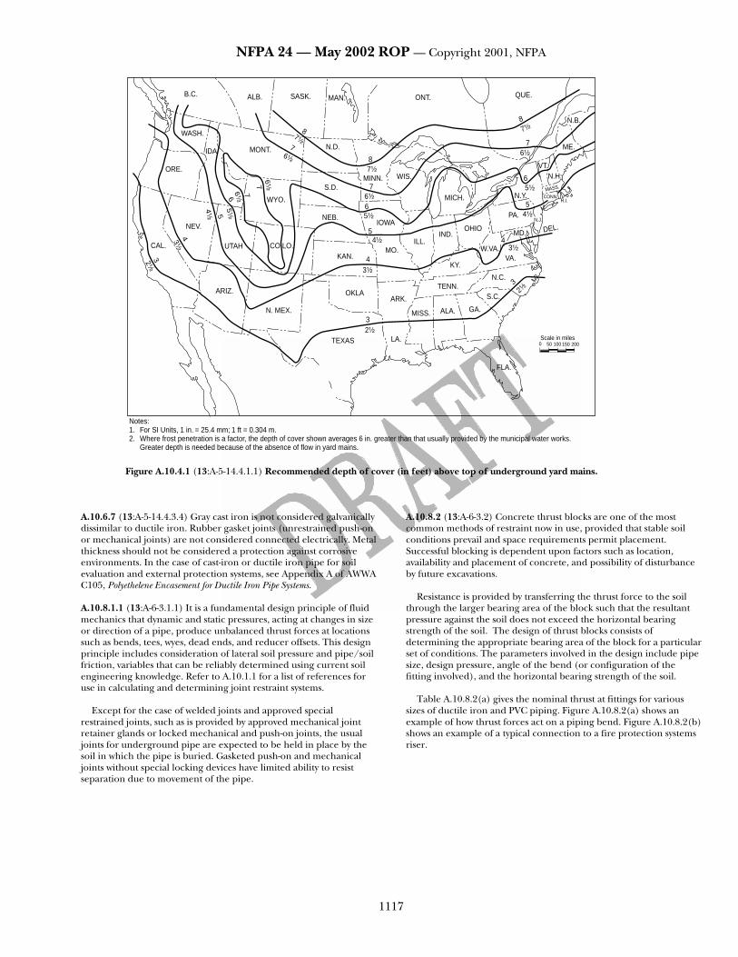
NFPA 24 — May 2002 ROP — Copyright 2001, NFPA
1117
A.10.6.7 (13:A-5-14.4.3.4) Gray cast iron is not considered galvanically dissimilar to ductile iron. Rubber gasket joints (unrestrained push-on or mechanical joints) are not considered connected electrically. Metal thickness should not be considered a protection against corrosive environments. In the case of cast-iron or ductile iron pipe for soil evaluation and external protection systems, see Appendix A of AWWA C105, Polyethelene Encasement for Ductile Iron Pipe Systems. A.10.8.1.1 (13:A-6-3.1.1) It is a fundamental design principle of fluid mechanics that dynamic and static pressures, acting at changes in size or direction of a pipe, produce unbalanced thrust forces at locations such as bends, tees, wyes, dead ends, and reducer offsets. This design principle includes consideration of lateral soil pressure and pipe/soil friction, variables that can be reliably determined using current soil engineering knowledge. Refer to A.10.1.1 for a list of references for use in calculating and determining joint restraint systems.
Except for the case of welded joints and approved special restrained joints, such as is provided by approved mechanical joint retainer glands or locked mechanical and push-on joints, the usual joints for underground pipe are expected to be held in place by the soil in which the pipe is buried. Gasketed push-on and mechanical joints without special locking devices have limited ability to resist separation due to movement of the pipe.
A.10.8.2 (13:A-6-3.2) Concrete thrust blocks are one of the most common methods of restraint now in use, provided that stable soil conditions prevail and space requirements permit placement. Successful blocking is dependent upon factors such as location, availability and placement of concrete, and possibility of disturbance by future excavations.
Resistance is provided by transferring the thrust force to the soil through the larger bearing area of the block such that the resultant pressure against the soil does not exceed the horizontal bearing strength of the soil. The design of thrust blocks consists of determining the appropriate bearing area of the block for a particular set of conditions. The parameters involved in the design include pipe size, design pressure, angle of the bend (or configuration of the fitting involved), and the horizontal bearing strength of the soil.
Table A.10.8.2(a) gives the nominal thrust at fittings for various
sizes of ductile iron and PVC piping. Figure A.10.8.2(a) shows an example of how thrust forces act on a piping bend. Figure A.10.8.2(b) shows an example of a typical connection to a fire protection systems riser.
B.C.
Notes:1. For SI Units, 1 in. = 25.4 mm; 1 ft = 0.304 m.2. Where frost penetration is a factor, the depth of cover shown averages 6 in. greater than that usually provided by the municipal water works.
Greater depth is needed because of the absence of flow in yard mains.
ALB. SASK. MAN. ONT.
WASH.
IDA
ORE.
MONT.
CAL.
32¹⁄₂
3¹⁄₂
4
UTAH
NEV.
4¹⁄₂ 5
5¹⁄₂
ARIZ.
N. MEX.
CO LO.
WYO.
NEB.
KAN.
OKLAARK.
TENN.
MISS. ALA. GA.
S.C.
N.C.
KY.
W.VA.VA.
3
4
5
3
LA.
FLA.
TEXAS2¹⁄₂
3¹⁄₂
4¹⁄₂
MO.ILL.
IND.OHIO
PA.
43¹⁄₂
MD. DEL.N.J.
R.I.
MASS.
N.Y. CONN.
N.H.
ME.
VT.
6
7
N.B.
4¹⁄₂
5
5¹⁄₂
6¹⁄₂
MICH.
WIS.MINN.
5¹⁄₂
66¹⁄₂
7
IOWA
S.D.
N.D.
87¹⁄₂
76¹⁄₂
7¹⁄₂
8
6¹⁄₂7
76¹⁄₂6
7¹⁄₂8
2¹⁄₂
QUE.
Scale in miles0 50 150100 200
Figure A.10.4.1 (13:A-5-14.4.1.1) Recommended depth of cover (in feet) above top of underground yard mains.

NFPA 24 — May 2002 ROP — Copyright 2001, NFPA
1118
A = 36π(D′)2
D′ = Outsidediameter ofpipe (ft)
∆ = (90 − θ) 2
PA
V
Y PAV
X
θ
Tx
Ty T
∆
Y
Tx = PA (1 − cos θ)
Ty = PA sin θ
T = 2 PA sin θ 2
X
T = Thrust force resulting from change in direction of flowTx = Component of the thrust force acting parallel to the original
direction of flowTy = Component of the thrust force acting perpendicular to the
original direction of flowP = Water pressureA = Cross-sectional area of the pipe interiorV = Velocity in direction of flow
Figure A.10.8.2(a) [13:A-6-3.2(a)] Thrust forces acting on a bend.
System riser
Cast-iron flangeand spigot piece
Cast-iron belland spigot pipe
Rods
Fire servicemain
Figure A.10.8.2(b) [13:A-6-3.2(b)] Typical connection to a fire protection system riser.
Thrust blocks are generally categorized into two groups — bearing
and gravity blocks. Figure A.10.8.2(c) depicts a typical bearing thrust block on a horizontal bend.
The following are general criteria for bearing block design: (1) The bearing surface should, where possible, be placed against
undisturbed soil. (2) Where it is not possible to place the bearing surface against
undisturbed soil, the fill between the bearing surface and undisturbed soil must be compacted to at least 90 percent Standard Proctor density.
(3) Block height (h) should be equal to or less than one-half the total depth to the bottom of the block (Ht) but not less than the pipe diameter (D).
(4) Block height (h) should be chosen such that the calculated block width (b) varies between one and two times the height.
Table A.10.8.2(a) [13:A-6.3.2(a)] Thrust at Fittings at 100 psi (6.9 bar) Water Pressure for Ductile Iron and PVC Pipe Total Pounds
Nominal Pipe Diameter (in.)
Dead End
90-Degree Bend
45-Degree Bend
221/2-Degree Bend
111/4-Degree Bend
51/8-Degree Bend
4 1,810 2,559 1,385 706 355 162 6 3,739 5,288 2,862 1,459 733 334 8 6,433 9,097 4,923 2,510 1,261 575 10 9,677 13,685 7,406 3,776 1,897 865 12 13,685 19,353 10,474 5,340 2,683 1,224 14 18,385 26,001 14,072 7,174 3,604 1,644 16 23,779 33,628 18,199 9,278 4,661 2,126 18 29,865 42,235 22,858 11,653 5,855 2,670 20 36,644 51,822 28,046 14,298 7,183 3,277 24 52,279 73,934 40,013 20,398 10,249 4,675 30 80,425 113,738 61,554 31,380 15,766 7,191 36 115,209 162,931 88,177 44,952 22,585 10,302 42 155,528 219,950 119,036 60,684 30,489 13,907 48 202,683 286,637 155,127 79,083 39,733 18,124 Notes: 1. For SI units, 1 lb = 0.454 kg. 2. To determine thrust at pressure other than 100 psi (6.9 bar), multiply the thrust obtained in the table by the ratio of the pressure to 100 psi (6.9 bar). For example, the thrust on a 12-in., 90-degree bend at 125 psi (8.6 bar) is 19,353 125/100 = 24,191 lb.
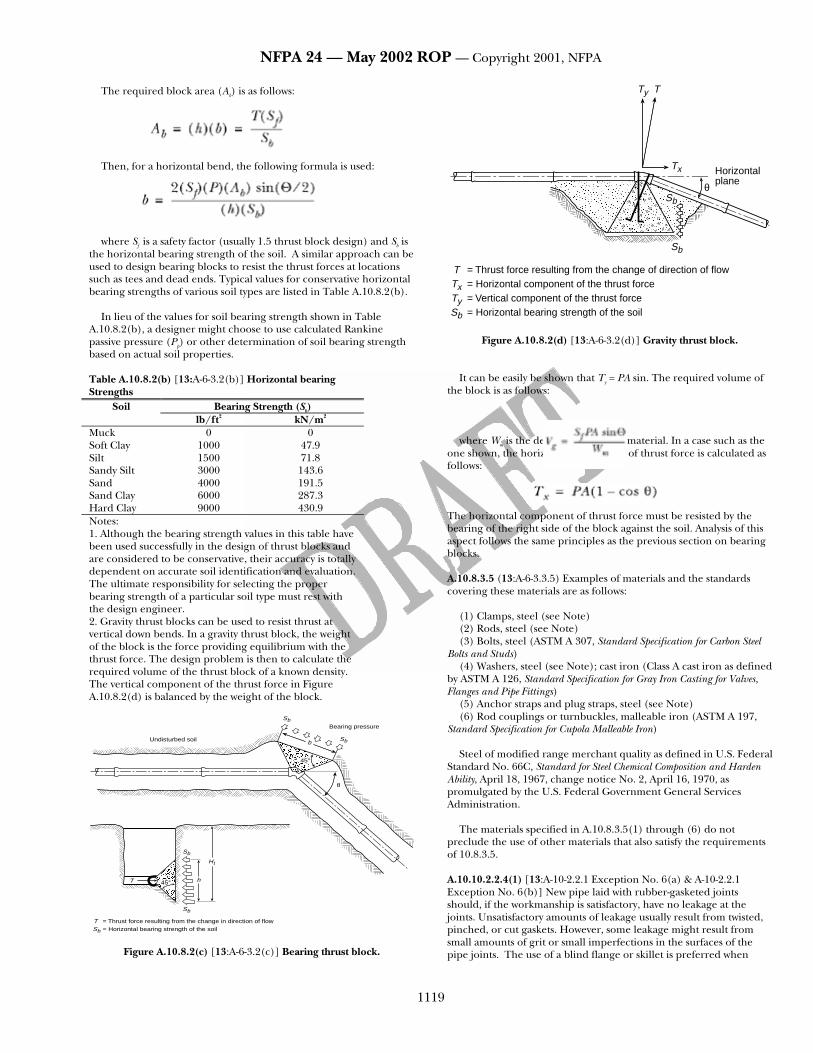
NFPA 24 — May 2002 ROP — Copyright 2001, NFPA
1119
The required block area (Ab) is as follows:
Then, for a horizontal bend, the following formula is used:
where Sf is a safety factor (usually 1.5 thrust block design) and Sb is
the horizontal bearing strength of the soil. A similar approach can be used to design bearing blocks to resist the thrust forces at locations such as tees and dead ends. Typical values for conservative horizontal bearing strengths of various soil types are listed in Table A.10.8.2(b).
In lieu of the values for soil bearing strength shown in Table
A.10.8.2(b), a designer might choose to use calculated Rankine passive pressure (Pp) or other determination of soil bearing strength based on actual soil properties. Table A.10.8.2(b) [13:A-6-3.2(b)] Horizontal bearing Strengths
Soil Bearing Strength (Sb) lb/ft2 kN/m2 Muck 0 0 Soft Clay 1000 47.9 Silt 1500 71.8 Sandy Silt 3000 143.6 Sand 4000 191.5 Sand Clay 6000 287.3 Hard Clay 9000 430.9 Notes: 1. Although the bearing strength values in this table have been used successfully in the design of thrust blocks and are considered to be conservative, their accuracy is totally dependent on accurate soil identification and evaluation. The ultimate responsibility for selecting the proper bearing strength of a particular soil type must rest with the design engineer. 2. Gravity thrust blocks can be used to resist thrust at vertical down bends. In a gravity thrust block, the weight of the block is the force providing equilibrium with the thrust force. The design problem is then to calculate the required volume of the thrust block of a known density. The vertical component of the thrust force in Figure A.10.8.2(d) is balanced by the weight of the block. aaaaaaaaaaaaUndisturbed soil b
SbBearing pressure
Sb
θ
45°aaaaaaaa45°
Sb
Sb
Ht
hT
T = Thrust force resulting from the change in direction of flowSb = Horizontal bearing strength of the soil
Figure A.10.8.2(c) [13:A-6-3.2(c)] Bearing thrust block.
Ty T
Tx
θ
Horizontalplane
Sb
Sb
T = Thrust force resulting from the change of direction of flowTx = Horizontal component of the thrust forceTy = Vertical component of the thrust forceSb = Horizontal bearing strength of the soil
Figure A.10.8.2(d) [13:A-6-3.2(d)] Gravity thrust block.
It can be easily be shown that Ty = PA sin. The required volume of the block is as follows:
where Wm is the density of the block material. In a case such as the
one shown, the horizontal component of thrust force is calculated as follows: The horizontal component of thrust force must be resisted by the bearing of the right side of the block against the soil. Analysis of this aspect follows the same principles as the previous section on bearing blocks. A.10.8.3.5 (13:A-6-3.3.5) Examples of materials and the standards covering these materials are as follows:
(1) Clamps, steel (see Note) (2) Rods, steel (see Note) (3) Bolts, steel (ASTM A 307, Standard Specification for Carbon Steel
Bolts and Studs) (4) Washers, steel (see Note); cast iron (Class A cast iron as defined
by ASTM A 126, Standard Specification for Gray Iron Casting for Valves, Flanges and Pipe Fittings)
(5) Anchor straps and plug straps, steel (see Note) (6) Rod couplings or turnbuckles, malleable iron (ASTM A 197,
Standard Specification for Cupola Malleable Iron)
Steel of modified range merchant quality as defined in U.S. Federal Standard No. 66C, Standard for Steel Chemical Composition and Harden Ability, April 18, 1967, change notice No. 2, April 16, 1970, as promulgated by the U.S. Federal Government General Services Administration.
The materials specified in A.10.8.3.5(1) through (6) do not preclude the use of other materials that also satisfy the requirements of 10.8.3.5. A.10.10.2.2.4(1) [13:A-10-2.2.1 Exception No. 6(a) & A-10-2.2.1 Exception No. 6(b)] New pipe laid with rubber-gasketed joints should, if the workmanship is satisfactory, have no leakage at the joints. Unsatisfactory amounts of leakage usually result from twisted, pinched, or cut gaskets. However, some leakage might result from small amounts of grit or small imperfections in the surfaces of the pipe joints. The use of a blind flange or skillet is preferred when
NFPA 24 — May 2002 ROP — Copyright 2001, NFPA
1120
hydrostatically testing segments of new work. Metal-seated valves are susceptible to developing slight imperfections during transport, installation, and operation and thus can be likely to leak more than 1 fl oz (30 ml) per inch of valve diameter per hour. For this reason, the blind flange should be used when testing hydrostatically. A.10.10.2.2.4(2) ) [13:A-10-2.2.1 Exception No. 6(a) & A-10-2.2.1 Exception No. 6(b)] New pipe laid with rubber-gasketed joints should, if the workmanship is satisfactory, have no leakage at the joints. Unsatisfactory amounts of leakage usually result from twisted, pinched, or cut gaskets. However, some leakage might result from small amounts of grit or small imperfections in the surfaces of the pipe joints. The use of a blind flange or skillet is preferred when hydrostatically testing segments of new work. Metal-seated valves are susceptible to developing slight imperfections during transport, installation, and operation and thus can be likely to leak more than 1 fl oz (30 ml) per inch of valve diameter per hour. For this reason, the blind flange should be used when testing hydrostatically.
Annex B Informational References B.1 Referenced Publications. The following documents or portions thereof are referenced within this standard for informational purposes only and thus are not part of the requirements of this document unless also listed in Chapter 2. B.1.1 NFPA Publications. National Fire Protection Association, 1 Batterymarch Park, P.O. Box 9101, Quincy, MA 02269-9101.
NFPA 20, Standard for the Installation of Stationary Pumps for Fire Protection, 1999 edition.
NFPA 22, Standard for Water Tanks for Private Fire Protection, 1998
edition. NFPA 72, National Fire Alarm Code , 1999 edition. NFPA 1962, Standard for the Care, Use, and Service Testing of Fire Hose
Including Couplings and Nozzles, 1998 edition.
B.1.2 Other Publications. B.1.2.1 ACPA Publication. American Concrete Pipe Association, 8320 Old Courthouse Road, Vienna, VA 20005.
Concrete Pipe Handbook. B.1.2.2 ASME Publications. American Society of Mechanical Engineers, Three Park Avenue, New York, NY 10016-5990.
ASME B16.1, Cast-Iron Pipe Flanges and Flanged Fittings for 25, 125, 250 and 800 lb. B.1.2.3 ASTM Publications. American Society for Testing and Materials, 100 Barr Harbor Drive, West Conshohocken, PA 19428-2959.
ASTM A 126, Specification for Gray Iron Castings for Valves, Flanges and Pipe Fittings, 1993.
ASTM A 197, Specification for Cupola Malleable Iron, 1987. ASTM A 307, Specification for Carbon Steel Bolts and Studs, 60,000 psi
Tensile Strength, 1994. ASTM C 296, Standard Specification for Asbestos-Cement Pressure Pipe,
1988.
ASTM E 380, Standard Practice for Use of the International System of Units, 1991.
B.1.2.4 AWWA Publications. American Water Works Association, 6666 West Quincy Avenue, Denver, CO 80235.
AWWA C104, Cement Mortar Lining for Ductile Iron Pipe and Fittings for Water, 1990.
AWWA C105, Polyethylene Encasement for Ductile Iron Piping for Water
and Other Liquids, 1988. AWWA C110, Ductile Iron and Gray Iron Fittings, 3-in. Through 48-in.
for Water and Other Liquids, 1987. AWWA C111, Rubber Gasket Joints for Ductile Iron Pressure Pipe and
Fittings, 1990. AWWA C115, Flanged Ductile Iron Pipe with Threaded Flanges, 1988. AWWA C150, Thickness Design of Ductile Iron Pipe, 1981. AWWA C151, Ductile Iron Pipe Centrifugally Cast in Metal Molds or
Sandlined Molds, for Water or Other Liquids, 1986. AWWA C153, Ductile Iron Compact Fittings, 3 in. through 24 in. and 54
in. through 64 in. for Water Service. AWWA C203, Coal-Tar Protective Coatings and Linings for Steel Water
Pipelines Enamel and Tape — Hot Applied, 1986. AWWA C205, Cement-Mortar Protective Lining and Coating for Steel
Water Pipe 4 in. and Larger — Shop Applied, 1989. AWWA C206, Field Welding of Steel Water Pipe, 1988. AWWA C208, Dimensions for Fabricated Steel Water Pipe Fittings, 1983. AWWA C300, Reinforced Concrete Pressure Pipe, Steel-Cylinder Type, for
Water and Other Liquids, 1989. AWWA C301, Prestressed Concrete Pressure Pipe, Steel-Cylinder Type, for
Water and Other Liquids, 1984. AWWA C302, Reinforced Concrete Pressure Pipe, Non-Cylinder Type, for
Water and Other Liquids, 1987. AWWA C303, Reinforced Concrete Pressure Pipe, Steel-Cylinder Type,
Pretensioned, for Water and Other Liquids, 1987. AWWA C400, Standard for Asbestos-Cement Distribution Pipe, 4 in.
Through 16 in., for Water and Other Liquids, 1980. AWWA C401, Standard Practice for the Selection of Asbestos-Cement Water
Pipe, 1983. AWWA C600, Standard for the Installation of Ductile-Iron Water Mains
and Their Appurtenances, 1982. AWWA C602, Cement-Mortar Lining of Water Pipe Lines 4 in. and
Larger — in Place, 1989. AWWA C603, Standard for the Installation of Asbestos-Cement Water
Pipe, 1978. AWWA 606, Standard for the Installation of Ductile-Iron Water Mains
and Their Appurtenances. AWWA C900, Polyvinyl Chloride (PVC) Pressure Pipe, 4 in. Through 12
in., for Water and Other Liquids, 1989.

NFPA 24 — May 2002 ROP — Copyright 2001, NFPA
1121
AWWA M11, Steel Pipe — A Guide for Design and Installation, 1989. AWWA M14, Backflow Prevention and Cross Connection Control, 1990
edition. AWWA M17, Installation, Maintenance, and Field Testing of Fire
Hydrants, 1980 edition. AWWA M41, Ductile Iron Pipe and Fittings.
B.1.2.5 DIRPA Publications. Ductile Iron Pipe Research Association, 245 Riverchase Parkway, East, Suite 0, Birmingham, AL 35244.
A Guide for the Installation of Ductile Iron Pipe. Thrust Restraint Design for Ductile Iron Pipe.
B.1.2.6 UBPPA Publication. Uni-Bell Plastic Pipe Association, 2655 Ville Creek Drive, Dallas, TX 75234.
Handbook of PVC Pipe. B.1.2.7 U.S. Government Publication. U.S. Government Printing Office, Washington, DC 20402.
U.S. Federal Standard No. 66C, Standard for Steel Chemical Composition and Harden Ability, April 18, 1967 change notice No. 2, April 16, 1970, as promulgated by the U.S. Federal Government General Services Administration.