next generation interconnect cabling for antenna applications … · title of slide next generation...
TRANSCRIPT

Title of Slide Title of Slide
Next Generation
Interconnect Cabling For Antenna Applications
Antenna Systems 2014
Presentation
Donald Bradfield – General Manager
Southwest Microwave, Inc. – Tempe, AZ USA

Title of Slide
In general, technologies that incorporate Antenna
Systems have advanced through the years:
• Performance: Tri-band E for 95 GHz
• Size: Battery miniaturization for UAV
• Ruggedness: Guided weapons, battlefield
wearable communications
Perception is that Cable Assemblies and
Interconnections have not advanced as rapidly.
In fact, significant advancements in this area have
contributed to a vast improvement in Antenna
Systems.
Presentation Focus

Title of Slide
Introduction Who is Southwest Microwave?
What solutions do we offer?
Today’s Problems
Weight, Space, Reliability, RF/Microwave Performance
Solutions
Concepts, Technology Involved, Flight History
Implementation
Options and How to proceed.
Q & A
Presentation Outline

Title of Slide
• History
– Incorporated 1981
– Formation of 2 Divisions
(Interconnect and Security Systems)
• Facilities
– 50,000 Square Feet (built 1999)
– 130 Employees
– Machine Shop, Heat Treat, Etc.
– Hi-Rel/Space Acceptance Testing
• Features
– Engineering Support - Owned & Managed by Engineers (founders
were founders of Omni Spectra & established M/A COM Connector
& Cable Assy. operations).
– Reliability, Hi-Rel (all connectors have materials traceability and
lot control). All production has testing.
– All products are PRODUCED in USA! 100% Compliant for RoHS,
DFARS steel, REACH, ISO 9001:2008, Conflict Minerals, etc.
Southwest Microwave Profile

Title of Slide
– Weight: Always too heavy
– Size / Volume: Always too large
– Reliability
• For Ruggedized Environments
• MIL-HDBK-217 (MTBF)
– Ease of Field Maintenance, etc.
• Simplify Cabling, Interconnections
Major Problems for Antenna Cabling
Application Challenges
Title of Slide
Focusing on RF/Microwave/mmWave
Interconnections
• Higher Frequencies
• Greater Bandwidth
• Multi-function, Frequency sharing
• Survivability
New Application Requirements
Title of Slide
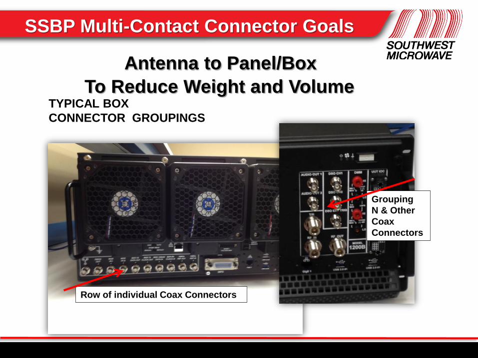
Row of individual Coax Connectors
Grouping
N & Other
Coax
Connectors
TYPICAL BOX
CONNECTOR GROUPINGS
Antenna to Panel/Box
To Reduce Weight and Volume
SSBP Multi-Contact Connector Goals
Title of Slide
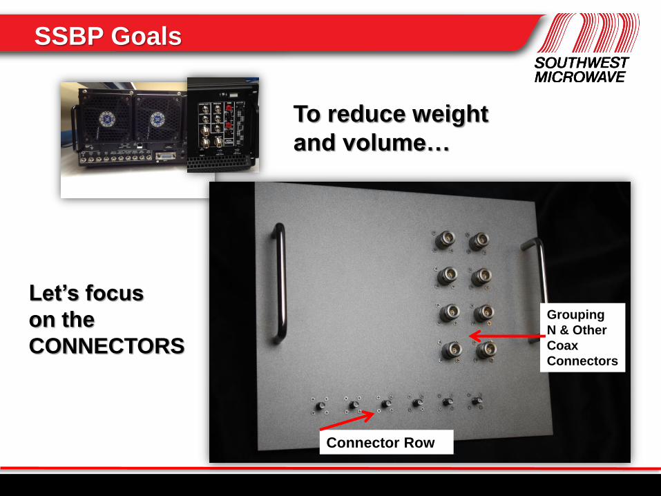
To reduce weight
and volume…
Let’s focus
on the
CONNECTORS
Connector Row
Grouping
N & Other
Coax
Connectors
SSBP Goals

Title of Slide
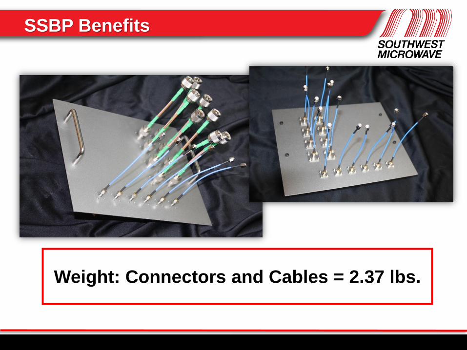
Front
Back (SMA only)
Front has
“N” and “SMA”
With basic
cables
SSBP Benefits
Title of Slide
Weight: Connectors and Cables = 2.37 lbs.
SSBP Benefits

Title of Slide
THIS
Can be REPLACED by ………
Size 12” x 10”
Front Rear Size Shown
7” x 7”
but could be
4” x 4”
Weight : Cables and Connectors = 0.49 lbs. (vs. 2.37 lbs.)
All cables are 6” for all options.
SSBP Benefits

Title of Slide
Connectors are Standard MIL-DTL-38999
BACC63CT21-16PNH Plug and BACC63CU21-16SNH Receptacle
14 Size 16 “SSBP” Coax assemblies
and 2 Signal Lines
DC to
67
GHz
Outstanding mmWave Performance
Results for “system”
SSBP Performance

Title of Slide
• Space & weight savings versus individual microwave connectors.
• Cost savings with “one” coax contact rather than a mix of connector types.
• Can mix contact types (DC signal, power, fiber-optic, and…now… microwave)
• Coax contacts are used with “connector types” already accepted by customers
SSBP Advantages

Title of Slide
THIS
Can be REPLACED by ………
Size 12” x 10”
Front Rear
Size Shown
7” x 7”
but could be
3” x 3”
Weight : Cables and Connectors = 0.23 lbs. (vs. 2.37 lbs.)
Front
Rear
0.9mm SuperMini
50 ohm Coax
SSBP Benefits

Title of Slide
Standard MIL-DTL-24308 D-Subminiature Connector
Application has 14 Size 20 “SSBP” Coaxes and 1 Signal Line
SSBP in Off-the-shelf Connectors

Title of Slide
Tested to 5,000 mating cycles
Ask for Test Report.
SSBP Test Data

Title of Slide
Environmentally Sealed, Ruggedized
Protected in D38999 Connectors
SSBP Coaxes tested Vibration to
2000 Hz, random & sine at 150ºC
with continuity. Also, shock
100 G’s 3X per all 3 axes.
(Test report available)
SSBP Test Data

Title of Slide
Reduced Weight, Miniaturization, Higher Bandwidth.
SMA (X, Ka Bands)
Plug + Panel Jack = 5.0 grams
0.9mm (DC to V Band)
Plug + Panel Jack = 0.56 grams
SMA 0.9mm
SSBP Benefits
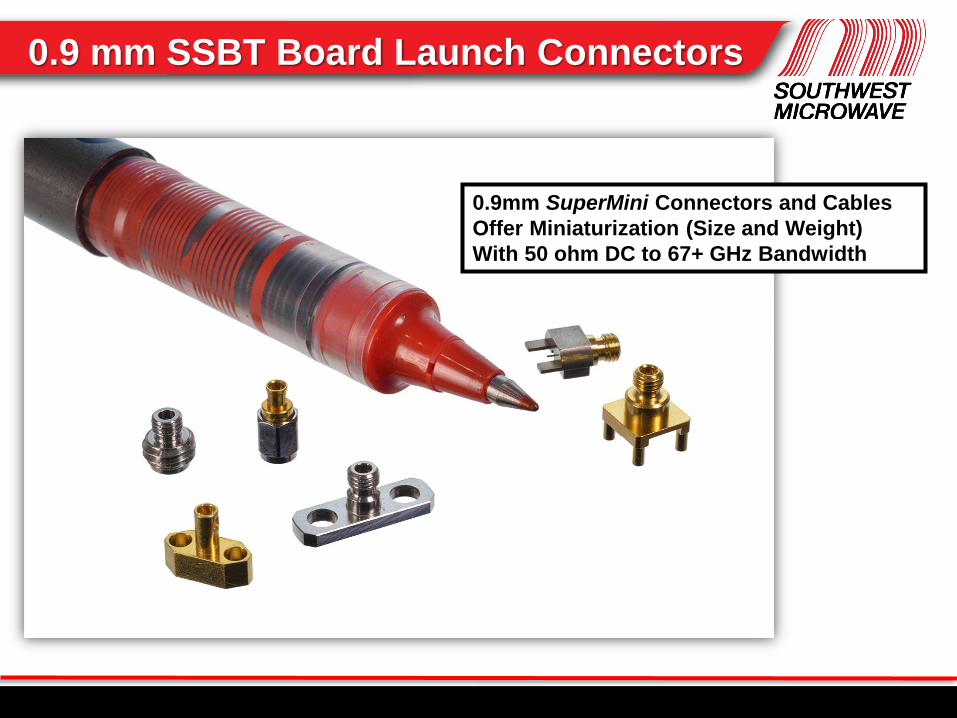
Title of Slide 0.9 mm SSBT Board Launch Connectors
0.9mm SuperMini Connectors and Cables
Offer Miniaturization (Size and Weight)
With 50 ohm DC to 67+ GHz Bandwidth

Title of Slide VALUE Through Broadband Performance
1.85mm
0.9mm
Plug &
Board
Mount
1.85mm
.047
Flex
Cable
Title of Slide
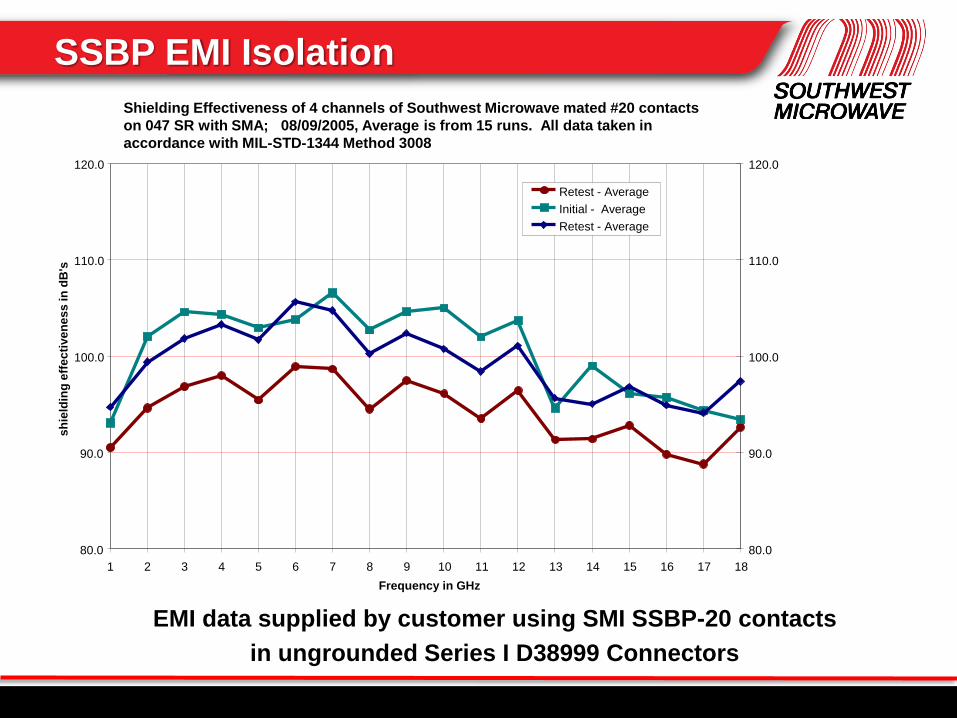
EMI data supplied by customer using SMI SSBP-20 contacts
in ungrounded Series I D38999 Connectors
SSBP EMI Isolation
Shielding Effectiveness of 4 channels of Southwest Microwave mated #20 contacts
on 047 SR with SMA; 08/09/2005, Average is from 15 runs. All data taken in
accordance with MIL-STD-1344 Method 3008
80.0
90.0
100.0
110.0
120.0
1 2 3 4 5 6 7 8 9 10 11 12 13 14 15 16 17 18
Frequency in GHz
sh
ield
ing
eff
ec
tive
ne
ss
in
dB
's
80.0
90.0
100.0
110.0
120.0
Retest - Average
Initial - Average
Retest - Average

Title of Slide
Coaxes in multi-pin connectors are more reliable
than groups of equal numbers of discrete coaxes.
“1” Mating, Using Hi-Shock, Vibration-Resistant,
Environmentally-Sealed “Proven” Connectors.
Reliability Predictions per MIL-HDBK-217F, Notice 2
SSBP Reliability

Title of Slide
Space and weight
savings vs. individual
microwave connectors
Simplified cabling
using off-the-shelf
connectors
Systemic cost savings
Miniaturized packaging
Improved reliability
Broadband microwave
performance
SSBP Multi-Contact Connector Benefits

Title of Slide
These contacts fit standard
off-the-shelf connectors!
D38999 Sizes 8, 12, 16 & 20 Sizes 16 & 20 contacts shown
D-Sub with Size 20 contacts
SSBP Contact Sizes
Title of Slide
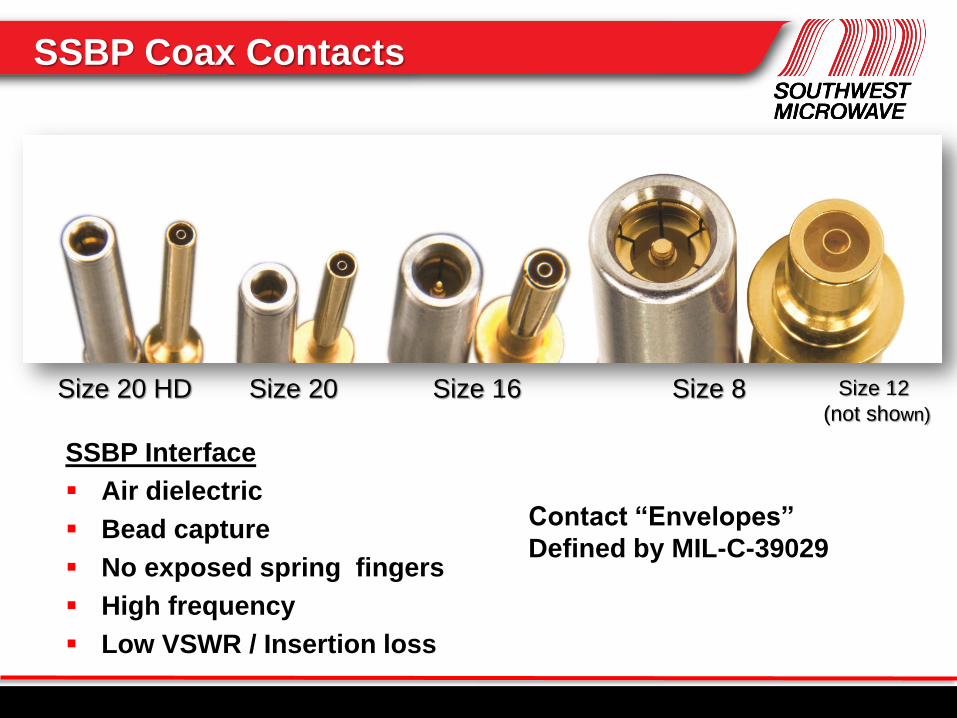
SSBP Interface
Air dielectric
Bead capture
No exposed spring fingers
High frequency
Low VSWR / Insertion loss
Size 20 HD Size 20 Size 16
Contact “Envelopes”
Defined by MIL-C-39029
Size 8 Size 12
(not shown)
SSBP Coax Contacts
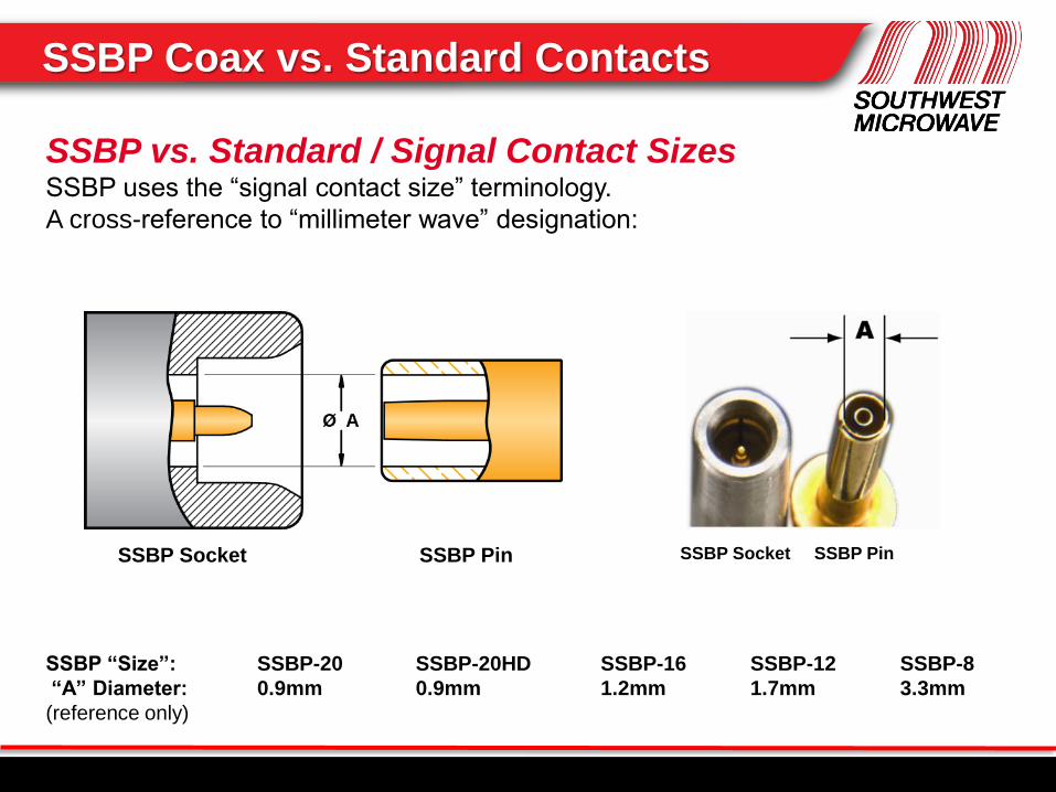
Title of Slide SSBP Coax vs. Standard Contacts
SSBP vs. Standard / Signal Contact Sizes SSBP uses the “signal contact size” terminology.
A cross-reference to “millimeter wave” designation:
SSBP “Size”:
“A” Diameter:
(reference only)
SSBP-20
0.9mm
SSBP-20HD
0.9mm
SSBP-16
1.2mm
SSBP-12
1.7mm
SSBP-8
3.3mm
SSBP Socket SSBP Pin SSBP Socket SSBP Pin

Title of Slide
MIL-DTL-38999
Series I, III & IV
Using standard MIL-I-816659 Insertion / Extraction
tools (same as those used on M39029 signal contacts)
SSBP to Signal Contact Comparison

Title of Slide
Miniature Connectors:
“SSBP” Coaxes also for Mighty Mouse Series 80
And, their RECTANGULAR equivalent Series 79…
SSBP Options

Title of Slide
Size 20 SSBP in Micro-D Package
6 Position Cable to PCB 6 Position Cable to Cable
SSBP Adaptability

Title of Slide
Space Savings with Micro-D
6 Individual
Coax Connectors
(Need space for turning
coupling nuts)
6-Position Micro-D
With SSBP-20.
Flying 7 years w/ LMCO.
Diamond
Shaped base
To Reduce
Weight
Vs.
SSBP Package Miniaturization

Title of Slide
Cable Termination Sequence
1. Cable insertion into SSBP cable bushing followed by center conductor
insertion into the socket contact inside the rear of the SSBP coax. Center
contact is NOT soldered.
2. Bottoming of tinned cable outer conductor against the step in the I.D. of the
SSBP cable housing.
3. Soldering outer conductor directly into the I.D. of the SSBP cable bushing.
SSBP Cable Termination

Title of Slide
Several Recently Completed Cables
with SSBP Coax Assemblies…
SSBP Successes
Title of Slide
1. SSBP coaxes provide unprecedented performance,
density, application flexibility and reliability.
2. SSBP applications are possible in most standard
connectors that use M39029 contacts.
3. SSBP designs are adaptable for special applications,
including discrete coax installations.
4. SSBP coaxes offer expanded design choices formerly
unavailable for antenna cables.
5. Southwest Microwave offers unique capabilities to
combine multi-contact and RF/microwave
connectors.
Summary: SSBP Benefits

Title of Slide Microwave Coax for Standard Connectors

Title of Slide Title of Slide
Thank you for your time and attention!
Are there any questions?
Presentation Q & A