newcastle university · 2014. 2. 20. · paul arkley, steve riddle school of computing science,...
TRANSCRIPT
Benefits of Traceability in Software Development
Thesis by Paul Arkley. School of Computing Science,
Newcastle University.
In Partial Fulfilment of the Requirements for the Degree of Doctor Philosophy.
2007
Newcastle University
NEWCASTLE UNIVERSITY LIBRARY
206 53508 6 ----------------------------
~n:;ffi1"':J k~ l 4-li-

For starters I'll have "Who?", "What?", "When?", "Where?" and the "Wither?",
"Whence?" and "Wherefore?" to follow, and one big side order of "Why?"
(Zpaphod Beeblebrox in the Hitch-Hikers Guide to the Galaxy, by Douglas
Adams, writer, 1952-2001)
11

Acknow ledgements
I would like to thank, first and foremost, my PhD supervisor Dr Steve Riddle for
his patience, guidance and his abundant supply of red ink. Secondly, I would like
to thank my family and colleagues, in particular John Fitzgerald, Cristina Gacek
and Jim Armstrong, for their help and encouragement in those dark days of
writing-up. Thirdly, I would like to thank Dr Tom Brookes (BAE SYSTEMS) for
his guidance in the practical aspects of Traceability. Finally, I would like to thank
Professor Tom Anderson and the BAE SYSTEMS customers of the Dependable
Computing Systems Centre for affording me the opportunity to undertake this
thesis.
iii

Publications The following papers have been published from this work:
Presented at the 18t International Workshop on Traceability in Emerging Forms of Software Engineering in conjunction with the 1 i" IEEE International Conference on Automated Software Engineering September 28 th
, 2002 Edinburgh, U.K.
Abstract
Position Paper: Enabling Traceability Paul Arkley, Paul Mason, Steve Riddle
School of Computing Science, University of Newcastle upon Tyne
NEl7RU United Kingdom
Research into traceability at the University of Newcastle upon Tyne has concentrated on a framework supporting all aspects of the lifecycle, as a vehicle for recording, analysing and tracing development and assessment artefacts. This framework is focussed on the recording of design rationale, over and above the standard inter-relationships between product artefacts, and has been developed in an aerospace systems engineering context. Despite technological advances in terms of databases, internet and processing power, many aspects of the requirements traceability problem are still current. We look at the reasons for this and suggest some research areas to address some of these aspects.
Presented at the 13 th IEEE International Requirements Engineering Conference, La Sorbonne, France, August 29-September 2,2005.
Abstract
Overcoming the Traceability Benefit Problem Paul Arkley, Steve Riddle
School of Computing Science, University of Newcastle upon Tyne,
NE17RU, UK
To modify complex computer-based systems requires a detailed understanding of their functionality. Requirements Traceability can help the engineer to gain that understanding, but several surveys have observed that traceability information is poorly recorded. We argue that the cause is the lack of direct perceived benefit to the main development process. As a consequence traceability information will be
iv

incomplete, inaccurate and out-of-date. We propose a method of recording traceability information, a Traceable Development Contract (TDC), as a means of reducing this problem by tackling the issue of an upstream functional development team imposing changes on a downstream development team. The contract makes the recording of traceability information beneficial to both development teams.
Presented at the 14th IEEE International Requirements Engineering Conference, Minneapolis/St. Paul, USA, September 11-15, 2006 and at the BAE SYSTEMS SPIRE Conference, Hinckley, Leicestershire, UK, October 23-26,2006.
Abstract
Tailoring Traceability Information to Business Needs Paul Arkley, Steve Riddle
School of Computing Science, University of Newcastle upon Tyne,
NEI7RU, UK
Tom Brookes BAE SYSTEMS, Electronics and Integrated Solutions, Plymouth, UK
Several surveys over the past 20 years have observed that traceability information is often poorly recorded. In previous work, we have argued that this is a result of many requirements traceability systems failing to provide any direct benefit to the development process. In this paper, we describe an application of traceability by a company, with a resulting increase in profitability as well as other benefits for the development engineer, project management and customer.
v

Abstract
For an engineer to be able to modify successfully a complex computer-based
system, he will need to understand the system's functionality. Traceability can
help the engineer to gain that understanding, but several surveys have observed
that traceability information is poorly recorded. This thesis argues, based on a
survey of nine aerospace projects, that one of the main causes of poor recording is
that Traceability does not directly benefit the development process. The recording
of traceability information is best performed by the engineers directly involved in
the development process, yet it is precisely these engineers who seem to obtain no
direct benefit in performing this task. This can be summarised as the Traceability
Benefit Problem. To overcome this problem the recording of traceability data
must provide immediate, tangible benefits to the engineers involved in the current
development process.
A related problem that occurs in large multi-team projects that follow
development processes based on predictive models (such as Waterfall or V
Model) is the changing of interface documentation without adequate negotiation
(referred to as Throwing the Problem over the Wall). This thesis describes, in
detail, how a small automotive sensor project addressed these problems by
developing a Requirements Traceability system that enabled the reuse of software
and provided a basis for the negotiation of changes with their customer. Analysis
of the lessons learnt from the automotive sensor and aerospace projects lead to the
definition of the Traceable Development Contract.
The contribution of this thesis is the description and discussion of the Traceable
Development Contract, a method of coordinating the interaction of related
development teams in development process that is based on a predictive
development model. The Traceable Development Contract is proposed as a means
of controlling the upstream team bias with respect to the imposition of changes,
by employing traceability to provide a basis for the negotiation of change. By
VI

employing traceability in this way, it becomes beneficial to the development
engineers and therefore overcomes the Traceability Benefit Problem.
Finally, the thesis considers how the Traceable Development Contract traceability
information can be exploited further to provide solution maturity and design
metrics.
VB

Table of Contents Acknowledgements ................................................................................................ iii
Publications ............................................................................................................ iv
Abstract .................................................................................................................. vi
Table of Contents ................................................................................................. viii
Table of Figures ................................................................................................... xiv
Chapter 1 Introduction ..................................................................................... 1
1.1 Introduction.................................................... ......................................... 1
1.2 Thesis Hypothesis ................................................................................... 2
1.3 Thesis Contribution ................................................................................. 3
1.4 Background to Proposed Solution ........................................................... 3
1.5 Proposed Solution ................................................................................... 5
1.6 Thesis Structure ....................................................................................... 5
Chapter 2 Traceability ..................................................................................... 9
2.1 Introduction ............................................................................................. 9
2.2 Origins of Traceability ............................................................................ 9
2.3 Literature Definitions ............................................................................ 12
2.4 The Need for Traceability ..................................................................... 16
2.4.1 Customer ........................................................................................... 16
2.4.2 Project Manager ................................................................................ 16
2.4.3 Requirements Analyst ....................................................................... 16
2.4.4 Designer ............................................................................................ 17
2.4.5 Maintainer ......................................................................................... 17
viii

2.5 Traceability Link Semantics ................................................................. 17
2.5.1 Traceability Models .......................................................................... 18
2.6 Traceability Representation Techniques ............................................... 21
2.6.1 Matrices ............................................................................................. 22
2.6.2 Entity Relationship (EIR) Model ...................................................... 22
2.6.3 Cross-referencing .............................................................................. 22
2.7 Traceability Tools ................................................................................. 23
2.7.1 Generic Tools .................................................................................... 23
2.7.2 Software Engineering Tools .............................................................. 24
2.7.3 Requirements Traceability Tools ...................................................... 25
2.8 Summary ............................................................................................... 26
Chapter 3 A Survey of Traceability Practices ............................................... 27
3.1 Introduction ........................................................................................... 27
3.2 Traceability Practice Survey Objectives ............................................... 27
3.3 Survey Design ....................................................................................... 28
3.4 Conducting the Survey .......................................................................... 29
3.5 Survey Results ....................................................................................... 31
3.5.1 Traceability Tools ............................................................................. 32
3.5.2 Development Practices ...................................................................... 33
3.5.3 Development Communications ......................................................... 34
3.5.4 Perceived Costs and Benefits ............................................................ 35
3.5.5 Organisation & Culture ..................................................................... 36
3.5.6 Traceability Comprehension ............................................................. 36
3.6 Reflections on Traceability Practice ..................................................... 37
3.7 Previous Traceability Practice Surveys ................................................. 38
lX

3.8 Comparison of Surveys ......................................................................... 41
Chapter 4 The Traceability Benefit Problem ................................................. 43
4.1 Introduction ........................................................................................... 43
4.2 The Burden of Data Entry ..................................................................... 43
4.3 Establishing a Relationship ................................................................... 47
4.4 Traceability Benefit Problem ................................................................ 48
Chapter 5 Automotive Sensor Case Study ..................................................... 51
5.1 Introduction ........................................................................................... 51
5.2 Automotive Sensor Case Study ............................................................. 51
5.3 Development Process ............................................................................ 53
5.3.1 Prepare Inputs for a ProposaL .......................................................... 54
5.3.2 Manage, Analyse, Develop System Requirements ........................... 54
5.3.3 Design ............................................................................................... 55
5.3.4 Prepare Test and Qualification Procedures ....................................... 56
5.4 An Illustration of the Traceability System ............................................ 56
5.4.1 Managing Requirements and the Customer ...................................... 57
5.4.2 Quantitative Management ................................................................. 59
5.4.3 Component Reuse ............................................................................. 60
5.4.4 Further Examples of Reuse ............................................................... 62
5.5 Why is this System Successful? ............................................................ 63
5.5.1 The Development Engineer's View Point... ...................................... 63
5.5.2 The Manager's View Point ............................................................... 63
5.5.3 The Customer's View Point.. ............................................................ 64
5.6 Summary ............................................................................................... 64
Chapter 6 Negotiating Change ....................................................................... 65
x

6.1 Introduction ........................................................................................... 65
6.2 Sequential and Iterative Development Models ..................................... 66
6.2.1 Sequential .......................................................................................... 66
6.2.2 Iterative ............................................................................................. 69
6.3 Agile Software Development. ............................................................... 70
6.4 BAE SYSTEMS Common Engineering Process Model (CEP) ............ 73
6.5 Observations and Summary .................................................................. 76
Chapter 7 Traceable Development Contract... ............................................... 79
7.1 Introduction ........................................................................................... 79
7.2 Origins of the Traceable Development Contract (TDC) ....................... 80
7.3 An Overview of the Traceable Development Contract.. ....................... 81
7.4 Contract Initiation ................................................................................. 83
7.5 Problem Discourse ................................................................................ 84
7.6 Proposed Solution ................................................................................. 86
7.7 Development & Refinement ................................................................. 88
7.8 Completion ............................................................................................ 89
7.9 Addressing Criticisms ........................................................................... 90
7.10 Summary ............................................................................................... 90
Chapter 8 TDC Traceability Data Structures ................................................. 93
8.1 Introduction ........................................................................................... 93
8.2 Influences of Existing Traceability Structures ...................................... 94
8.2.1 Problem-Solution Satisfaction Traceability ...................................... 94
8.2.2 Contribution Structures ..................................................................... 98
8.2.3 Design Rationale Capture System (DRCS) Language .................... 100
8.3 Influences of Traceability Practice Survey ......................................... 102
xi

8.4 TDC Traceability Data Structures Design .......................................... 103
8.4.1 Design Decisions ............................................................................. 104
8.5 Artefact. ............................................................................................... 105
8.6 Artefact Satisfaction ............................................................................ 107
8.7 Artefact Decomposition ...................................................................... 109
8.8 Artefact Validation .............................................................................. III
8.9 TDC Data Structure Summary ............................................................ 113
8.10 Summary ............................................................................................. 113
Chapter 9 An Illustration of the TDC .......................................................... liS
9.1 Introduction......................................................................................... liS
9.2 Background: Accipiter 300 ................................................................. 116
9.2.1 Mission Planning System ................................................................ 116
9.2.2 Development Organisation ............................................................. 117
9.2.3 Scope of Illustration ........................................................................ 117
9.2.4 Use of Traceability .......................................................................... 11 8
9.2.5 The Introduction of the TDC .......................................................... 118
9.3 Initiation .............................................................................................. 119
9.3.1 Example Mission Computer Problem Artefacts ............................. 119
9.3.2 Comparing and Contrasting with FET Systems' Approach ............ 122
9.4 Problem Discourse .............................................................................. 122
9.4.1 Comparing and Contrasting with FET Systems' Approach ............ 126
9.5 Proposed Solution ............................................................................... 127
9.5.1 Comparing and Contrasting with FET Systems' Approach ............ 134
9.6 Development & Refmement ............................................................... 134
9.6.1 Comparing and Contrasting with FET Systems' Approach ............ 138
xii

9.7 Completion .......................................................................................... 138
9.7.1 Comparing and Contrasting with FET Systems' Approach ............ 139
9.8 Summary ............................................................................................. 140
Chapter 10 Lessons Learnt and Future Work ................................................ 143
10.1 Introduction ......................................................................................... 143
10.2 Identifying the Problem ....................................................................... 144
10.3 The Importance of Observation .......................................................... 145
10.4 Traceability Benefit Problem .............................................................. 147
10.5 Traceable Development Contract... ..................................................... 148
10.6 Further Work ....................................................................................... 149
10.6.1 The Implementation of the TDC ..................................................... 150
10.6.2 Solution Maturity ............................................................................ 152
10.6.3 Artefact Traceability - Arity and Distribution ................................ 154
10.7 Coda .................................................................................................... 157
Appendix A Traceability Survey: Preliminary Questions .................................. 159
Appendix B TDC Database Schema ................................................................... 165
Appendix C Example Accipiter Queries ............................................................. 167
Information Queries ........................................................................................ 167
Dialog Queries ................................................................................................ 168
Status Queries ...................................................................................... ·· .. · .... · .. 169
Satisfaction Queries ........................................................................................ 170
Bibliography ........................................................................................................ 171
xiii

Table of Figures Figure 2-1 Vertical and Horizontal Traceability [Mason 1999] ........................... 14
Figure 2-2 Vertical, Horizontal and Revision Traceability [Mason 1999] ........... 14
Figure 2-3 DoD Requirements Management ModeL .......................................... 20
Figure 2-4 DOORS Folder Window ...................................................... ............... 25
Figure 5-1 A typical ESP sensor package ........ ..................................................... 52
Figure 5-2 Understeer and Oversteer .................................................................... 53
Figure 5-3 Traceability Data Model (BAE SYSTEMS E&IS) ............................. 55
Figure 5-4 Project Milestones ............................................................................... 57
Figure 5-5 Classification of Project Requirements ............................................... 58
Figure 5-6 Requirements Changes ........................................................................ 58
Figure 5-7 Test Procedures ...................................................... ............................. 61
Figure 5-8 Test Cases ................................................. ........................................... 62
Figure 6-1 V Model -Software Development Model [IABG 2007]. .................... 67
Figure 6-2 Manifesto for Agile Software Development.. ..................................... 71
Figure 6-3 Development Method Continuum ............. .......................................... 72
Figure 6-4 CEP Development Processes ............................................................... 74
Figure 7-1 TDC applied to each development interface .. .......................... '" ........ 82
Figure 7-2 Overview ofTDC Stages: UML State Diagram ................................. 83
Figure 7-3 Problem Discourse: UML Activity Diagram ...................................... 85
Figure 7-4 Problem Solution Traceability ............................................................. 87
Figure 8-1 Simple Solution Satisfaction Traceability ........................................... 94
Figure 8-2 A Simplified UML Class Diagram of a Satisfaction Relationship .... 96
Figure 8-3 Refinement of Solution and Satisfaction Arguments .......................... 96
Figure 8-4 A Simple Problem Frame diagram ................................................. ..... 98
xiv

Figure 8-5 Contribution Structure Relationships: Artefact Evolution .................. 99
Figure 8-6 Artefact Synthesis ............................................................................. 100
Figure 8-7 Plan Synthesis ................................................................................... 101
Figure 8-8 Evaluation Structures Group ............................................................. 102
Figure 8-9 Problem & Solution Generalisation of a Common Artefact (UML Class Diagram) .................................................................................................... 105
Figure 8-10 Artefact Structure (UML Class Diagram) ....................................... 106
Figure 8-11 Artefact Satisfaction (UML Class Diagram) ................................... 108
Figure 8-12 Artefact Satisfaction: Problem and Solution Views (UML Class Diagram) ............................................................................................................. 109
Figure 8-13 Artefact Decomposition (UML Class Diagram) ............................. 110
Figure 8-14 Artefact Validation (UML Class Diagram) ..................................... 112
Figure 9-1 Positional Sensors ............................................................................. 116
Figure 9-2 UML Use Case Diagram: Down Load Flight Plan - Insert PDC ...... 121
Figure 9-3 Mission Computer Development Plan .............................................. 121
Figure 9-4 Organization Chart ............................................................................ 122
Figure 9-5 Logical Decomposition of the Accipiter Requirements .................... 123
Figure 9-6 Artefact Structure for Requirement 10.13 ......................................... 124
Figure 9-7 Prototype Package Decomposition .................................................... 127
Figure 9-8 Prototype Deployment Diagram ........................................................ 128
Figure 9-9 Artefact Decomposition - Package Diagram ..................................... 129
Figure 9-10 Artefact Satisfaction: Requirements and Tape Package .................. 130
Figure 9-11 Artefact Validation: Tape Package .................................................. 131
Figure 9-12 Comparison of Mission Computer Requirements ........................... 132
Figure 9-13 New Use Case Diagram .................................................................. 136
Figure 9-14 Example Compliance Matrix ........................................................... 140
Figure 10-1 Requirements Maturity Index .......................................................... 153
xv

Figure 10-2 Requirements Activity ..................................................................... 154
Figure 10-3 Trying to Satisfy Too Many Problem Artefacts .............................. 155
Figure 10-4 Problem Artefact Satisfied by Many Solution Artefacts ................. 156
Figure 10-5 Artefact G: Too Many Parent Artefacts .......................................... 156
Figure 10-6 Splitting Artefact G ....... .................................................................. 157
xvi

Chapter 1 Introduction
1.1
1.2
1.3
1.4
Introduction ........................................ .
Thesis Hypothesis ......................... ..
Thesis Contribution ........................... .
Background to Proposed Solution .......... .
. ................................ 1
................................ 2
................................. 3
......................................... 3
1.5 Proposed Solution ................................................................................... 5
1.6 Thesis Structure ....................................................................................... 5
1.1 Introduction
For an engineer to be able to modify successfully a complex computer-based
system, he will need to understand the system's functionality. One way to gain
this understanding is to review the development artefacts looking for common
threads of reasoning. Traceability' defined as, "a property of a system description
technique that allows changes in one of the three system descriptions -
requirements, specifications, implementation to be traced to the corresponding
portions of the other descriptions" [Greenspan and McGowan 1978] can help the
engineer to determine these threads.
Development standards such as ISO 9003 [ISO 2007] and TickIT [TickIT 2000]
require that a project shall be able to demonstrate Requirements Traceability.
I The tenl1 "Traceability" is often prefixed with "Requirements" to demonstrate the source of the
trace relationships. The general teml "Traceability" refers to the recording of all trace
re lationships.

These standards are unclear on precisely what information is required to be
recorded and to what use it should be put. Researchers have addressed this
problem by determining what development artefact properties and relationships
are required to be recorded to improve the efficiency of the development process
and the quality of the product. This research has mainly concentrated on the
evolution of requirements and as a result there are a number of requirements
management tools [INCOSE 2007] such as DOORS [DOORS 2003], which allow
the recording of traceability relationships between requirements. At present,
traceability is mainly applied to the requirements development phase and
traceability beyond that phase is seldom achieved in an industrial environment, as
demonstrated by the Traceability Practices Survey (Chapter 3).
1.2 Thesis Hypothesis
Given that Traceability is a desired or mandatory technique and there are proven
information structures and tools that support these structures, it seems odd that the
take-up and execution within industry is poor [Ramesh et al. 1993] [Gotel and
Finkelstein 1994] [Arkley 2002].
We argue that the lack of direct benefits to the main development process from
Traceability, which we define as the Traceability Benefit Problem, is a major
cause of the above situation. We state that the recording of traceability
information is best performed by the engineers who are directly involved in the
development process and it is these engineers who seem to obtain no benefit in
performing this task. This lack of benefits causes the development engineers and
their management to assign a very low priority to the recording of traceability
information, often resulting in data that is incomplete, inaccurate and out of date.
2

1.3 Thesis Contribution
The contribution of this thesis is the proposal of a Traceable Development
Contract, which consists of a process and information model for coordinating the
interaction of related development teams in development process that is based on
a predictive development model. The Traceable Development Contract is a means
of controlling the upstream team bias with respect to the imposition of changes,
by employing traceability to provide a basis for the negotiation of change. By
employing traceability in this way, it becomes beneficial to the development
engineers and therefore overcomes the Traceability Benefit Problem.
1.4 Background to Proposed Solution
A traditional view of the poor uptake and execution of Traceability is that it is a
technical problem, which can be improved by the greater integration of
development tools or by the use of search engines [ Herzog 2000] [Antoniol et al.
2002] [Marcus and Maletic 2003] [Huffman et al. 2006]
This thesis questions the technical based solution by considering the factors
involved in determining a trace between two artefacts belonging to different
development phases. An argument is made that only the engineers directly
involved in the development transformation, such as developing a design from the
requirements, can consistently record the correct relationships between
development artefacts. This argument is employed to validate the poor results
presently obtained by offline traceability recording teams (described in Chapter 3)
and search engines (described in Chapter 4).
From the results of a Traceability Practice Survey (Chapter 3), an argument is
developed that states engineers will only record this information consistently if it
is beneficial to their immediate development task: we refer to this as the
Traceability Benefit Problem.
3
One of the projects in the Traceability Practice Survey, the Automotive Sensor
project (Chapter 5), demonstrated how the Traceability Benefit Problem could be
overcome by the development of a traceability system that was beneficial to their
development process. The resulting traceability system enabled the reuse of
software and provided a basis for the negotiation of customer changes. The
automotive sensor project was unique among the surveyed projects as it was
developed by a small multidisciplinary team: the rest of the surveyed projects
were large multi-team projects that followed development processes based on
predictive development models.
The Traceability Practice survey (Chapter 3) highlighted a related issue that
occurs in large multi-team projects, where an upstream development team
imposes changes on a downstream team without any negotiation. This has been
observed by other researchers [AI-Rawas and Easterbrook 1996] [Curtis et al.
1988] [Christie et al.1996] and is often referred to as "Throwing the problem over
the wall". Development processes based on predictive development models have
the problem of establishing a suitable development phase baseline to allow
development to advance. Changes to baselines will always occur during
development.
Development models say little with respect to how teams involved in different
development phases should interact and negotiate change. Boehm tackled this
issue in his Theory-W of software management [Boehm and Ross 1989]. In this
theory, he states that negotiations require structure and objective information
about the proposed change. The determination of the impact of a change to a
development baseline is such an item of objective information. To determine the
impact of a change requires the recording of traceability relationships between the
baseline and the next development phase. This is how the Automotive Sensor
team beneficially employed traceability to negotiate change with their customer.
A similar use of traceability in the context of a structured interaction would make
4

the recording of traceability infonnation beneficial to both development phases
and therefore it would overcome the Traceability Benefit Problem for multi-team
development processes.
1.5 Proposed Solution
The Traceable Development Contract (TDC) is proposed as means of providing
structure and objective information to change negotiations. The IDC formalises
the interaction of two development teams by defming their behaviour with respect
to the state of their common development artefacts. Traceability is employed as a
means of assessing the impact of a change to the common development artefacts
and providing a basis for the negotiation of the change. The TDC affords the
engineers in the downstream development phase an element of control over their
development environment by controlling the imposition of changes by the
upstream development team. By keeping the definition of the TDC generic, for
example the interaction between an upstream problem defining phase (e.g.
software requirement definition) and a downstream development phase (e.g.
software design), the contract can be applied across a number of development
interfaces and therefore achieving traceability beyond the requirements
development phase. The TDC consists of three parts:
• Problem artefacts (documentation, diagrams, models etc) that describe the
problem domain.
• Traceabilitv data structures that record how the problem information artefacts
are related to a proposed solution. For example, traceability structures that
record the relationship between a software design and a requirement set.
• A protocol that defines the behaviour of each development phase with respect
to changes to the problem information artefacts or solution.
1.6 Thesis Structure
The thesis is divided into ten chapters.
5

Chapter 1 Introduction: This chapter lays the foundations for the thesis by
describing the technical problem, thesis hypothesis, thesis contribution, proposed
solution and finally the structure of the thesis.
Chapter 2 Traceability: This chapter describes the origins, development of
Traceability definitions and current implementation techniques. The aim of this
chapter is to provide a foundation for the following chapters by clarifying terms
and definitions.
Chapter 3 Traceability Practice Survey: This chapter describes motivation and
the method of a survey of traceability practices performed by a number of BAE
SYSTEMS projects. The results of the survey are compared and contrasted with
two widely cited studies on Requirements Traceability practice performed by
Gotel [Gotel 1995] and Ramesh [Ramesh and Jarke 1999b; Ramesh et al. 1995].
Chapter 4 Traceability Benefit Problem: This chapter builds upon Chapter 3 by
analysing the results of the Traceability Practice Survey in detail. From this
analysis, an argument is developed that states that one of the major causes of the
observed Requirements Traceability practice issues is the lack of benefit that it
provides to the current development process. We define this as the Requirements
Traceability Benefit Problem.
Chapter 5 Automotive Sensor Case Study: This chapter describes in detail how
Electronics and Integrated Solutions (E&IS), one of the BAE SYSTEMS
surveyed projects, developed a Traceability system which addresses Traceability
Benefit Problem. The chapter describes and illustrates with project data the
development process and traceability system. Finally, the chapter describes the
benefits the traceability system provides to the development engineer, the project
management and their customer.
Chapter 6 Negotiating Change: Chapter 5 described how the automotive sensor
project employed a traceability system to help them negotiate changes to their
6

baseline requirements. The Traceability Practice Swvey (Chapter 3) highlighted
the problem of establishing and maintaining development phase baselines. During
the swvey, a number of engineers raised issues relating to the fact that the re
issuing of interface documentation without any consultation or negotiation
(referred to as Throwing Problem over the Wall). This chapter examines the issue
of change negotiation by considering what software development models have to
say on the subject. Finally, the BAE SYSTEMS Common Engineering Process
Model (CEP) is reviewed as many BAE SYSTEMS development processes are
based on this or a similar development model. The CEP is reviewed with respect
to change negotiation and the results are related to the observations made during
the Traceability Practice Swvey.
Chapter 7 Traceable Development Contract: Chapter 6 highlighted the
weaknesses in predictive development models with respect to establishing
development phase baselines and the inherent bias these models have towards
upstream development phases making changes to the baseline. Chapter 5
described how the automotive sensor project employed a traceability system to
help them negotiate customer changes to their baseline requirements. This chapter
combines these themes and introduces the Traceable Development Contract
(TDC). The TDC is proposed as a means of controlling the upstream team bias
with respect to the imposition of changes, by employing traceability to provide a
basis for the negotiation of change. By employing traceability in this way, it
becomes beneficial to the development engineers and therefore overcomes the
Traceability Benefit Problem.
Chapter 8 TDC Traceability Data Structures: This chapter examines the data
structures required to achieve the aims of the TDC. This chapter describes how
design of the structures has been influenced by previous traceability structures and
the Traceability Practice Swvey. The chapter concludes by examining how the
TDC traceability data structures can be exploited further to provide solution
maturity and design metrics.
7

Chapter 9 An Illustration of the TDC: Chapter 7 outlined the IDC protocol and
Chapter 8 described the data structures required to support the contract. This
chapter builds upon this work by describing how a contract may work in practice.
To illustrate the IDC, and the complexity of the aerospace industry, this chapter
will consider the development of the Mission Planning System software for a
hypothetical Jet trainer. The illustration is not a proof or a validation of the IDC,
it is presented here as a means of exemplifying the ideas presented the previous
chapters.
Chapter 10 Lessons Learnt and Future Work: This chapter summarises the
problems and achievements of this work. The chapter describes the history of the
development of the ideas in this thesis and finally, discusses how the work
presented can be extended further.
8

Chapter 2 Traceability
2.1 Introduction ............................................................................................. 9
2.2 Origins of Traceability ......................................... ............................. 9
2.3 Literature Definitions ............................................................................ 12
2.4 The Need for Traceability ..................................................................... 16
2.5 Traceability Link Semantics ................................................................. 17
2.6 Traceability Representation Techniques ............................................... 21
2.7 Traceability Tools ................................................................................. 23
2.8 Summary ............................................................................................... 26
2.1 Introduction
This chapter investigates the origins of Traceability and the evolution of the
literature definitions. The chapter examines the need for Traceability in the
development process and summarises the data models and tools that have been
developed to achieve Traceability.
2.2 Origins of Traceability
The term Requirements Traceability appears to have been coined in the 1950s by
the US military during the development of electro-mechanical systems [Alford
1994]. During this period, Traceability broadly referred to the ability to
demonstrate that a system satisfied a set of requirements. As software engineering
developed from its electro-mechanical parentage, Requirements Traceability was
adopted and applied to the development of software. By the mid 1970s it became
apparent that software development required new techniques: this is commonly
referred to as the Software Crisis [Dijkstra 1972]. At this time Alford [Alford
9

1977] identified a need to improve traceability between system modelling and
system requirements and between requirements and the originating specification
documents. The 1970s also saw the introduction of the first requirements tracing
tools [Pierce 1978].
In the 1980s Boehm illustrated his Spiral model [Boehm 1986] by describing the
development of a Software Productivity System (SPS) which included a
Requirements Traceability Tool (RTT). The 1990s saw an upsurge in interest in
requirements traceability. This upsurge appeared to have two causes. The first
cause was the availability of commercial relational database systems for common
PC platforms, which lead to the development of commercial requirements
managements systems such as DOORS (Dynamic Object-Orientated
Requirements System2)[DOORS 2007] and RTM (Requirements and Traceability
Management system3)[RTM 2007]. This instilled interest in both the academic
and industrial communities on how these new tools could be best exploited.
The second cause appears to have been a related upsurge in interest in
Requirements Engineering [Gotel 1995]. There are many definitions of
Requirements Engineering though one of the most commonly cited is Definition
2-1. Though, the application of analysis methods to requirements dates back to the
1970s [IEEE 1977], Requirements Engineering became established in the early
1990s (the first International Symposium on Requirements Engineering was held
in 1993) when new requirements analysis methods were being developed.
2 DOORS was originally developed by Quality Systems and Software (QSS) in the early 1990s
and is currently being developed by Telelogic
3 RTM was originally developed by Marconi Systems Technology in the early 1990s and is
currently being developed by Serena.
10

Definition 2-1
Requirements Engineering
"Requirements engineering is the branch of software engineering concerned with
the real-world goals for functions of and constraints on software systems. It is also
concerned with the relationship of these factors to precise specifications of
software behaviour, and to their evolution over time and across software
families." [Zave 1997]
The 1990s saw significant advances in Requirements Engineering research such
as the development of techniques for eliciting and analysing stakeholders' goals,
modelling scenarios that characterise different contexts of use, the use of
ethnographic techniques for studying organisations and work settings, and the use
of formal methods for analysing safety and security requirements.
As Requirements Traceability is an aspect of Requirements Engineering it also
saw an increase in research effort. This research effort was initially directed at the
problem of requirement elicitation. This had been an ongoing problem in systems
development, as demonstrated by an early empirical study by Bell and Thayer
[Bell and Thayer 1976]. They observed that inadequate, inconsistent, incomplete
or ambiguous requirements are common and have an impact on the quality of the
resulting software. They stated that "The requirements for a system, in enough
detail for its development, do not arise natural/yo Instead, they need to be
engineered and have continuing review and revision" [Bell and Thayer 1976].
Boehm highlighted the cost of not getting the system requirements correct, stating
that the cost of correcting requirement related error increased rapidly as
development proceeded [Boehm 1981]. Requirements Traceability researchers
during this period tackled issues related to the recording and analysis of
requirement development rationale [Nuseibeh et al. 1994] [Riddle and Saeed
1998] [Riddle and Saeed 1999a] and the recording of contributions by
development actors [GoteI1995].
11

The new millennium saw the introduction of a wide range of Extensible Mark-up
Language (XML) [XML 2007] tools and this caused a change in the direction of
Requirements Traceability research. Researchers started explored how these tools
could be employed to record traceability relationships between diverse sources.
Two features of XML appeared to have created the most interest, the ability to
record metadata about an artefact in a known format, and use of the bidirectional
Xlinks [Xlink 2007]. A number of researchers [Alves-Floss et al. 2002][Anderson
et al 2002][Collard et al.2002][Zisman et al 2003] have proposed ways of
employing these XML technologies to create traceability information frameworks.
2.3 Literature Definitions
There have been a number of Traceability definitions. One of the earliest
definitions (Defmition 2-2) came from Greenspan & McGowan [Greenspan and
McGowan 1978].
Definition 2-2
Traceability is a property of a system description technique that allows changes in
one of the three system descriptions - requirements, specifications,
implementation- to be traced to the corresponding portions of the other
descriptions" [Greenspan and McGowan 1978]
This broad definition of traceability persisted until Davis introduced the idea of
direction to traceability relationships (Definition 2-3).
Definition 2-3
"Traceability can be defined as the ability to describe and follow the life of an
artefact, in both a forward and backward direction, i.e. from its origin to
development and vice versa" [Davis 1990]
12

The introduction of a notion of direction to traceability relationships influenced a
number of researchers. One of the most notable contributions was from Gotel who
employed this idea to tackle the problem of pre-requirements elicitation. Gotel
expanded upon Davis's earlier definition to establish a defmition for Pre and Post
Requirements Traceability (Definition 2-4).
Definition 2-4
"Pre-requirements traceability (pre-RT) refers to the ability to describe and follow
those aspects of a requirement's life prior to its inclusion in the requirements
specification in both a forwards and backwards direction (i.e., requirements
production and refinement).
Post-requirements traceability (post-RT) refers to the ability to describe and
follow those aspects of a requirement's life that result from its inclusion in the
requirements specification in both a forwards and backwards direction (i.e.,
requirements deployment and use)". [GoteI1995]
A number of researchers [Bersoff and Davis 1991] [Gote1 1995] [Mason 1999]
extended the notion of direction to establish a distinction between artefact version
(or horizontal) traceability and inter-development phase artefact (or vertical
traceability) as shown in Figure 2.1. Horizontal traceability occurs between
iterations of the same artefact, this is commonly known as version control.
Vertical traceability occurs between artefacts in different development phases, for
example relationships between a requirement specification and a design artefact.
Mason [Mason 1999] took this two dimensional view and argued the presence of
a third dimension (Figure 2-2) which captures the traceability relationships for a
given revision or release of a system.
13

&' :.0 co 1l
]~ .€ -" Cl > E
0-o -.; > " o
tQ ,
D.~~-
0, +------4 -~
Hori zontal Version Traceability
,
c) ,
·6
Key: Shapes represent artefacts belonging to a development phase. Shading represents the evolution of an artefact
Figure 2-1 Vertical and Horizontal Traceability IMason 19991
Revision Traceabli ity
Horizontal Version Traceabili ty
Figure 2-2 Vertical, Horizontal and Revision Traceability IMason 19991
The previous definitions are from the academic communi ty. The fo llowing text
which i taken fro m IEEE Recommended Practi ce for Software Requirements
14

Specifications [IEEE 1998] is presented here as an example of a working
description of Requirements Traceability.
"4.3.1 Correct
A Software Requirements Specification (SRS) is correct if, and only if, every
requirement stated therein is one that the software shall meet. There is no tool or
procedure that ensures correctness. The SRS should be compared with any
applicable superior specification, such as a system requirements specification,
with other project documentation, and with other applicable standards, to ensure
that it agrees. Alternatively the customer or user can determine if the SRS
correctly reflects the actual needs. Traceability makes this procedure easier and
less prone to error (see 4.3.8} ...
4.3.8 Traceable
An SRS is traceable if the origin of each of its requirements is clear and if it facilitates the referencing of each requirement in future development or
enhancement documentation. The following two types of traceability are
recommended:
a) Backward traceability (i.e., to previous stages of development). This depends
upon each requirement explicitly referencing its source in earlier documents.
b} Forward traceability (i.e., to all documents spawned by the SRS). This depends
upon each requirement in the SRS having a unique name or reference number.
The forward traceability of the SRS is especially important when the software
product enters the operation and maintenance phase. As code and design
documents are modified, it is essential to be able to ascertain the complete set
of requirements that may be affected by those modifications. " [IEEE 1998]
This definition tries to answer a criticism, which has been aimed at the previous
defmitions, that they all fail to state why requirements traceability should be
15

perfonned. This highlights a problem faced by many development managers who
are required to implement Requirements Traceability due to a need to be
compliant to a development standard. Many Requirements Traceability definitions
and development standards are unclear why it should be perfonned and what
benefits will be obtained by perfonning traceability. Without this infonnation, it is
difficult for these managers to detennine the correct level of effort to be assigned
to this task.
2.4 The Need for Traceability
The perceived need for Traceability is dependent on each stakeholder's view of
the development process.
2.4.1 Customer
For the Customer, Requirements Traceability is needed as a means of showing
that the product satisfies the requirements. This is achieved by demonstrating the
traceability relationships between acceptance tests and the requirements and also
design and the requirements.
2.4.2 Project Manager
For the project manager, Traceability provides a range of project status
infonnation. The rate of establishment of traceability relationships provides a
means of assessing progress. The distribution of traceability relationships can
highlight areas of high dependency or development bottlenecks. Traceability
provides the project manager a means of assessing the impact of a change,
allowing him to allocate the correct level of resource to the change.
2.4.3 Requirements Analyst
For the requirements analyst, Requirements Traceability provides a means of
recording the contribution of each stakeholder during requirements elicitation. It
16

also provides a means to check the correctness and consistency of the developing
requirements.
2.4.4 Designer
For the designer, Traceability provides a means of demonstrating that the design
satisfies the requirements and how it will be verified. The traceability relationship
between the design and the requirements allows the designer to determine the
impact of any changes to requirements on the design or the impact of design
changes on the ability to satisfy the requirements. Traceability also provides the
designer a means of recording design rationales and design alternatives, which can
be employed in a design justification.
2.4.5 Maintainer
For the maintainer, Traceability provides a means of gaining an understanding of
the product. By traversing the traceability relationships the maintainer is able to
determine the impact of a change. The traceability information also provides the
maintainer a means of determining the testing required to validate the systems
after a change.
2.5 Traceability Link Semantics
Each of the above development roles requires different set of link semantics to be
recorded. The following is a summary of the link semantics, which have appeared
in the literature.
• Requirements related links.
o Linking a requirement to its source documents. o Linking a requirement to the personal details of the stakeholders
who developed the requirement. o Linking a requirement to its change history (configuration and
control) o Linking a requirement to a justification, that gives the reasons for
the requirement
17

o Linking a requirement to subsystem requirements (requirements decomposition).
o Linking a requirement to design artefact(s). o Linking a requirement to a validation test(s).
• Design artefacts related links.
o Linking a deign artefact to the personal details of the stakeholders who developed the artefact.
o Linking a design artefact to requirements. o Linking a design artefact to subsystem design (design
decomposition). o Linking a design artefact to another artefact that describes the
problem domain from a different viewpoint. o Linking a design artefact to a design rationale. o Linking a design artefact to its change history (configuration and
control). o Linking a design artefact to a validation test(s).
• Code Module related links.
o Linking a code module to the personal details of the stakeholders who wrote the code.
o Linking a code module to design artefacts. o Linking a code module artefact to subsystem (code
decomposition). o Linking a code module to an implementation rationale. o Linking a code module to its change history (configuration and
control). o Linking a code module to a validation test(s).
This list is not definitive or exhaustive. It can be seen that there are similar
traceability relationships in each development phase (requirements, design and
code), such as the recoding of the stakeholder relationships. Given these common
traceability relationships, a number of researchers have proposed traceability
development models that describe how traceability relationships are recorded and
exploited during the development of a system.
2.5.1 Traceability Models
One of the first of these models was the evolution support environment (ESE)
system [Ramamoorthy et al.1990]. The ESE model considers a system to be
18

composed of a hierarchical structure of generic objects. These objects are
connected by three types of traceability link: hierarchical links between objects at
different levels of the hierarchy, historical links between versions of one object
and development links between different objects at different stages of
development. The ESE traceability model was implemented using the Ingres
relational database in conjunction with the UNIX SCCS version control system.
Gotel [Gotel 1995] considered problem of pre-requirements traceability, that is
recording the relationships with respect to contributions made to an evolving
requirement. In her thesis, Gotel addressed this problem by proposing a set of
Contribution Structures. The evolution of a requirement is represented by a
hierarchy of artefacts connected by either change relationships or reference
relationships. Contributors are related to requirement artefacts by contribution
relations that are defined by their role in the development process.
The ESPRIT NATURE project demonstrated a prototype Requirements
Engineering environment called PRO-ART [Pohl 1996]. The PRO-ART tool
allows the tracing of the development or evolution of a requirement in three
dimensions.
Representation Dimension: This ranges from informal to formal. Moving along
this dimension is technical problem. The dimension records the representation of a
requirement from informal notes, structured text and finally to formal
specification.
Agreement Dimension: This ranges from partial to complete and is orthogonal to
the representation dimension. Moving along this dimension is a social process.
This is represented by issues about which decision must be made. An issue may
be related to an object in the specification dimension. About each issue, one or
more positions are stored and for each position a rationale is recorded.
19

Specification Dimension: This dimension ranges from opaque to complete
understanding of the requirement. Movement along this dimension represents the
cognitive and psychological problems of the requirements engineering. This
dimension is orthogonal to agreement and representation dimensions.
The DoD traceability model has evolved from the work of Ramesh and Edwards
[Ramesh et al. 1995] at the Naval Postgraduate School in Monterey. Ramesh and
Edwards developed a number of interrelated traceability models by observing
current development practices and from interviews with engineers working on
large DoD software development contracts. Their models consisted of a
requirements management model, a design to implementation model, decision
rationale model and compliance verification model. Each of these models contains
a set of permissible information types and a set of permissible relationships. For
example, Figure 2-3 describes the requirements management model.
Derive
Based On
Figure 2-3 DoD Requirements Management Model
Derive Compliance Verification Procedure
These models were further extended and refined by Ramesh and Jarke [Ramesh
and Jarke 1 999a] (CREWS project). The models were implemented using
ConceptBase [ConceptBase 2007] and the SLATE engineering development tool
(now obsolete). Ramesh claimed that these models were successful though he
restated older problems relating to tool implementation and development
20

processes which he raised in 1995 with Edwards [Ramesh, Stubbs, Powers and
Edwards 1995].
Another example of a traceability data model is the Meta-Modelling Approach to
Traceability for Avionics (MATra) [Mason 1999]. MATra is an object-based
approach to tracing artefacts for the development and assessment of aviation
electronic (avionics) systems. It is based on a set of interconnected "traceability
structures" specified using the class diagram view from the UML, with integrity
constraints over these structures expressed in the Object Constraint Language
(OCL).
Though not a traceability data model, the AP233 application protocol data model
[Herzog 2000], is designed primarily to support design data exchange between
software engineering tools, and provides some design traceability capabilities.
This data model was developed to allow systems engineering development tools
to share data.
However, there is still no clear agreement on a common traceability model as
there are an unlimited number of traceability relations which can be recorded and
as Wieringa [Wieringa 1995] stated: "the ultimate traceability tool is the world".
What these models have demonstrated, in particular Contribution Structures and
the DoD reference model, is how traceability can be applied to the development
process to answer relevant development needs. A successful strategy for
developing a traceability model, as demonstrated by the success of Gotel's and
Ramesh's traceability models, is to start with a very simple model and to expand
on this as the organisation gains an understanding of its rigour and usefulness.
2.6 Traceability Representation Techniques
Wieringa [Wieringa 1995] categorised the methods of representing a traceability
relationship as matrices, entity relational models and cross referencing.
21

2.6.1 Matrices
A matrix is the simplest and the most common way representing a traceability
relationship. The horizontal and vertical dimensions represent the artefacts that are
to be linked. A mark at an intersection indicates a traceability link. AU the links
have the same semantics.
2.6.2 Entity Relationship (E/R) Model
EIR modelling is one of the best known semantic modelling approaches. It can be
employed to describe the traceability links between entities. This technique has an
advantage over the traceability matrix, in that links with higher arity than 2 (the
maximum for a traceability matrix) can be represented. EIR Models can also be
represented by relational database management systems (RDBMS) and this allows
the ad hoc queries and reports to be made on the link data. Many of the
commercial Requirements Traceability tools, such as DOORS [DOORS 2007]
and RTM [RTM 2007], employ EIR modelling and relational database
management systems to represent traceability relationships.
2.6.3 Cross-referencing
Cross-referencing is arguably the oldest traceability technique yet it has been
given a new life with introduction of mark-up languages such as HTML and
XML. In Cross-referencing the semantics of the link is contained in the text
surrounding the reference. The link is represented by textual directions or in the
case of HTML or XML by hypertext linking. Cross-referencing is simple to
understand, though the traceability links are always binary and unidirectional.
There are a number of examples of prototype project cross-referencing schemes,
which employ tagging, numbering and indexing to implement traceability
[Jackson 1991] [Zisman et al. 2003].
22

2.7 Traceability Tools
Tool support for Requirement Traceability can be divided into the following broad
categories:
• Generic tools, such as spreadsheets, word processors, hypertext editors and
database management systems (DBMS),
• Software Engineering Tools which provide traceability features.
• Requirements Traceability Tools, which provide dedicated requirements
traceability support.
2.7.1 Generic Tools
The tools that fall into this category are word processors, spreadsheets editors,
hypertext editors and database management systems (DBMS). These tools, with
the exception of database management systems, mainly support cross-referencing
traceability. Microsoft Excel is commonly employed to create traceability
matrices.
Since Kaindl [Kaindl 1993] demonstrated how hypertext technology could be
employed to record requirements traceability, HTML and XML editors have
greatly increased in complexity and functionality though the basic referencing
concepts that he described remain unchanged. The same can also be said of the
work performed by Watkins and Neal [Watkins and Neal 1994], who described
how common desktop tools could be employed to record requirements
traceability. Since their work, Microsoft's dominance of the desktop market has
resulted in a reduction of tools vendors but a greater integration of the Office
products which overall has been beneficial to the execution of Requirements
Traceability .
Database management systems (DBMS) can be employed to implement ER
models that represent traceability relationships [Riddle and Saeed 1999b].
However, the direct use of a DBMS requires an understanding of relational
23

database theory and SQL, which many practicing development engineers may not
have. This has resulted in the development of dedicated Requirements
Traceability tools, such as DOORS, which aim to hide the DBMS functionality
from the engineer. The use of generic tools can be summarised as follows:
• They mainly support cross-referencing traceability techniques.
• They are readily available to all project members.
• They are generally easily understood (with the possible exception of DBMS)
and require little training.
• They are flexible, though this may come with the incurred cost of developing
bespoke scripts.
• They generally don't support any form of data analysis (with the possible
exception of DBMS )
2.7.2 Software Engineering Tools
The prime aim of this group of tools is to provide a software development service
and a traceability facility is just one of the many features provided. Most of the
tools which fall into this class are Computer Aided Systems Engineering (CASE)
tools, such as CRADLE [Cradle-5 2007]. This class of tools allow the
development of objects to be traced, though this trace information is often limited
to version control information. The use of software engineering tools can be
summarised as follows:
• They sometimes only offer limited traceability data recording and analysis
facilities. (Traceability is only one of the facilities offered by these tools).
• They do not easily allow traces to be made to information outside the tool's
domain.
• They can be complex and require staff training to make use of the full
potential of the traceability features.
• They are well suited to large projects as they allow distributed and controlled
access to data.
24

2.7.3 Requirements Traceability Tools
This class of tools is mainly aimed at providing requirements traceability, though
they can be employed to provide traceability throughout a project 's lifetime. At
present, there are two tools which dominate this area, DOORS (Dynamic Object
Oriented Requirements System) [DOORS 2007] , and RTM (Requirements and
Traceability Management system) [RTM 2007]. A survey of traceability tool
features has been performed by INCOSE [INCOSE 2007] .
The market leader, DOORS has the ability to import a range of documents and to
decompose them into a hierarchy of records based on the structure of the original
document. Traceability between documents is achieved by link modules, which
record the relationship between individual records. Documents are organised in
fo lders akin to an operating system file system: Figure 2-4. The ease of use of the
import functionality and the intuitive use of folders has been the key to the
success of the DOORS tool.
II /DOORS Database/SoHwam Projects/DOORS Family/DOORS/DOORS Black · DOORS I!t~~
DOORS Dalabase D Company Siandards CJ M anagemenl Projecls ·0 Services Projecls
B CJ Sofiware Projecls i B D DOORS Family : I 8 CJ DOORS
i 8~ D a I I: Iii CPS sub'projecl i I IiJ D Desi9n
1· ~ El<perimental Des
j. GUI Redesign SUj '1 D Requiremenls
I I' S yslem R equI
I I I D User Requirel r' Softwdre : D Tesl
Tesl DUse Cases ~ M eating M inules
~ Producl Plan ~ Projecl Plans
Figure 2-4 DOORS Folder Window
25
Project
PrOlect Folder An desi9n docu:nentation Folder Designs used to lesl new Ideas
Folder An requirements documents Folder Code dalalor delaaed Iraceabillty Folder AU lesl speciflCalions Folder Traced 10 Requiements Formal Weekly meelrn9s Formal Producl Plan Formal Development Protecl Plans

2.8 Summary
In summary, the practice of Traceability in software development has a long
history and a number of data models and tools that have been developed to allow
the engineer to make use of this valuable resource (as described in section 2.4).
The next chapter considers the practical aspects of recording Traceability
information by examining how a number of aerospace projects practice
traceability.
26

Chapter 3 A Survey of Traceability Practices
3.1 Introduction ........................................................................................... 27
3.2 Traceability Practice Survey Objectives ............................................... 27
3.3 Survey Design ....................................................................................... 28
3.4 Conducting the Survey .......................................................................... 29
3.5 Survey Results ....................................................................................... 31
3.6 Reflections on Traceability Practice ..................................................... 37
3.7 Previous Traceability Practice Surveys ................................................. 38
3.8 Comparison of Surveys ....................................................................... 41
3.1 Introduction
Management from a number of BAE SYSTEMS projects reported that there were
issues in recording Traceability information in an industrial context. These issues
were concerned with encouraging engineers to record and maintain Traceability
infonnation. The result of these concerns was a survey of how a number of BAE
SYSTEMS projects practiced traceability.
This chapter describes the survey of traceability practices conducted on a number
of BAE SYSTEMS projects. The motivation and the method of the survey are
described here. The results of the survey are compared and contrasted with two
widely cited studies on traceability practice performed by Gotel [Gotel 1995] and
Ramesh [Ramesh et a1. 1995].
3.2 Traceability Practice Survey Objectives
As stated in Chapter 2 there are many different Traceability implementation
models and tools, each of which have their own particular strengths and
27
weaknesses. However, BAE SYSTEMS project management were reporting
issues with the recording and maintenance of Traceability information. With this
in mind, a survey BAE SYSTEMS projects was undertaken, to understand the
state of traceability practice. The objectives of this survey were to investigate how
each of the projects currently performs Traceability and to determine what
elements of "best practice" could be applied across the company.
3.3 Survey Design
Give the above objectives, the first stage in the development of a survey design is
the determination of the unit of analysis [Babbie 1990]. The unit of analysis is
what or whom is being studied. In the initial survey design, the units of analysis
were a number of aerospace related projects, which were of a similar scale and
complexity. After a trial run of an early version of the Preliminary Questionnaire
it was found that this selection was too coarse and the units of analysis should be
the engineers on the projects.
The next stage was to determine the type of survey to be conducted, cross
sectional or longitudinal. A cross-sectional study involves observing a subset of
the population all at the same time, while a longitudinal study involves repeated
observations of the same subset over long periods of time. The limited access to
project engineers, due to their work commitments, favoured a cross-sectional
survey. This decision was supported by the fact that the development methods and
tools were unlikely to change during development and if repeated surveys were
possible it is was unlikely that they would be no more illuminating than the first.
Therefore, a cross-sectional survey was selected.
The final stage in the survey design was to determine how to conduct the survey:
by questionnaires, interviews or a combination of these techniques. The trial run
of the Preliminary Questionnaire helped to answer this question. These
questionnaires were completed poorly and it was during discussions with
28

engineers that had completed them that it was discovered that a form could not
identify all the issues. The outcome of these discussions was the decision that the
project engineers had to be interviewed to gain a true insight into the problems.
However, a questionnaire still provided a good basis for the interview and this
resulted in the modification of the initial questionnaire for that purpose, giving
rise to the Preliminary Questionnaire in Appendix A.
3.4 Conducting the Survey
The survey was confined to the BAE SYSTEMS projects which were members of
the Dependable Computing Systems Centre4 [DCSC 2007]. Five BAE SYSTEMS
divisions took part in the survey, Airbus (Filton), Avionics (Plymouth), MBDA
(Filton), CSS & Programmes (Brough and Warton). From each of these company
divisions the following product programmes took part:
• Airbus (Filton): A380 IMA, A380 Fuel Systems
• E&IS (Electronics and Integrated Solutions): Merlin, Sensors
• MBDA (Filton): Sea Dart, ASRAAM
• CSS & Programmes (Brough): Tornado, Gripen
• CSS & Programmes (Warton): Eurofighter/Typhoon
Nineteen engineers were interviewed individually in the course of this survey.
Their experiences ranged from an engineering graduate with six months
4 The Dependable Computing Systems Centre (DCSC) was founded in 1991 by BAE
SYSTEMS, the University of York and the University of Newcastle. The DCSC performs
research into dependable computing systems in conjunction with the BAE SYSTEMS
companies and its affiliated joint ventures. The Traceability Practice Survey was conducted
as part of the DCSC research programme.
29

experience to a head of department who had over twenty years experience of
aerospace development.
Before every site visit, the site survey sponsor was sent a general product
questionnaire (Appendix A). This questionnaire had two purposes. Firstly, it
helped the sponsor in selecting a suitable project and secondly, it allowed the
development of more targeted interview questions. The product questionnaire
covered the following four areas:
• The first area of questioning was related to the product. These questions were
intended to gain an overview of the product and its complexity.
• The second area of questioning related to determining the project's
organisation.
• The third section of the questionnaire investigated how the project
communicated.
• The final section of the questionnaire looked at what tools and protocols the
project teams were employing to overcome the problems related to
Traceability.
An interview schedule was drawn up from the information gathered from the
returned questionnaires. The interviews were conducted during a number of site
visits that occurred during 2002. The interviews were structured to gain the
maximum contribution from the engineer and were based on ideas presented in
standard texts [Babbie 1990;Leong and Austin 1996;Robinson 1993]. The
interviews were conducted in a relaxed, informal manner that helped to put the
engineer at ease and helped to dispel any ideas of the interview being some form
of quality audit.
Each interview started by the interviewer describing the aims of the survey to the
engineer, which involved giving a quick overview of the DCSC. This was
followed by the interviewer describing his background, engineering interests and
how they related to the survey. Once a rapport had been established, the engineer
30

was asked to describe his job function, his department and fmally the product that
he was currently working on.
The interview then concentrated on the Traceability tools employed on the
project. The engineer was encouraged to describe the benefits and pitfalls of these
tools and the environment that they were used in. In the fmal phase of the
interview, the engineer was asked for ideas to improve his Traceability tool set or
working environment. The engineer was invited to "think out of the box" by the
interviewer stating that he, the engineer, had "three wishes" that could be used to
bring about the ideal Traceability tool and working environment. This phase of
interview often proved to be most fruitful. The topics discussed often related to
deficiencies that had been covered earlier in the interview. The interview was
finished by the engineer being thanked for his contribution.
In the course of the survey, a total of fifteen hours of interviews were completed,
with the average length of an interview being approximately three quarters of an
hour. Throughout the interview, the interviewer would record informal written
notes that were later transcribed. This technique proved to be more successful than
recording, as many engineers appeared to be hampered by the presence of a
microphone.
3.5 Survey Results
The main conclusion of this survey was that "best practice" is not a simple matter
of selecting the correct Traceability tool or adopting a new method of working.
The survey raised a number of factors that influenced Traceability practice.
• Traceability Tools
• Development Practices
• Development Communications
• Cost! Benefits
• Organisation & Culture
31

• Traceability Comprehension.
3.5.1 Traceability Tools
The projects surveyed employed four different tools for Traceability:
DOORS[DOORS 2007], Cradle [Cradle-5 2007], Requirement Traceability
Management (RTM) [RTM 2007], and Product Version Control System
(PVCS)[PVCS 2007]. Only RTM and DOORS are dedicated Requirements
Traceability tools, while PVCS is a software configuration tool and Cradle is a
software engineering tool that is based on the Ward-Mellor method of software
development.
The majority of the surveyed projects only employed Traceability tools for
product verification. This use was highlighted by the method of deployment; on
many of the surveyed projects, the tools were maintained by a quality team that
was separate from the main development teams. This bias towards product
verification role was confirmed by a number of engineers who stated that
Traceability tools had no role to play in the development process and that these
tools were only a means of checking that all the Hi's had been dotted".
All the engineers surveyed expressed dissatisfaction with their Traceability tools,
with data entry being the most commonly quoted area of dissatisfaction. The need
for engineering data to be specially transcribed for the Traceability tools often
caused backlogs in data entry. These delays were often further increased due to
the lack of personnel who had the required training to manipUlate and format the
traceability data. The resulting slow data entry process often caused Traceability
database to be out-of-sync with the development process and as a result, the
Traceability data was mistrusted by the development engineers. A number of
projects tackled this problem by having the data entry performed by a dedicated
team (usually a team with a product quality function) who understood the
traceability tools. It was found that though this type of team organisation relieved
32

the development teams of the data entry burden, traces were not recorded
accurately and the data was still out-of-sync with the development process
How the tools displayed the Traceability data was heavily criticised by the
surveyed engineers. One development engineer stated, "You see everything or
nothing. You get swamped by the diagrams". This quote summed up the general
feeling among the surveyed engineers. The issue of data presentation caused many
development engineers to refrain from using a Traceability tool unless they had
had specialised training in the use of the tool and therefore could navigate the
Traceability data effectively.
A number of engineers stated that the Traceability tools force them to work in an
un-natural way, for example, one tool required all configured items to be
referenced by a number rather than by a textual name. This numeric indexing
caused confusion and time to be wasted in decrypting the numbers back into text.
Traceability tools were also found to be lacking in the narrow selection of source
media that could be traced. All the tools surveyed employed text as a base media
for Traceability, therefore these tools were are unable to offer any Traceability
functionality for diagrams, plans or mathematical algorithms. A number of
projects partly solved this problem by storing the changed diagram plan or
algorithm in a separate configuration database, such as PVCS, and then recording
a reference to the changed item in the RT tool.
The Traceability tools in the survey were found to be poor in the development of
collaborative products. It was often very difficult, due to firewalls and or security
policies, for a co-located subcontractor to view the required subset of the
Traceability data.
3.5.2 Development Practices
It was found that how system requirements were created, refmed and implemented
had a major bearing on Requirements Traceability. For example, engineers stated
33

that the way requirements were written often hindered Requirements Traceability.
A common complaint made by design engineers was that the requirements
documentation was written in such detail that these documents were in practice
pseudo design documents. These over elaborate requirements documents often
caused confusion about what the requirements really were and how the
requirements should be mapped onto a design. The following quotes made by
development engineers summarise the problem:
"The requirements documentation is too complex. the granularity is too fine"
"They (requirements engineers) have done my job for me ".
"Why did they (requirements engineers) want it to be implemented that way?"
Requirement Traceability was found to be confused when a set of functional
derived requirements was mapped onto an object-oriented design (OOD).
Engineers claimed that it was difficult to determine the correct level of mapping,
for a requirement may be satisfied by the parent object or by one or more of the
inherited specifications. This mapping confusion also affected software testing as
it was difficult to determine which objects should be tested against which
requirements. The engineers, who stated a view on this topic, stated that the
functional requirements to OOD mapping issues could be partly solved by the
adoption of an informal local mapping standard that dictated how functionality
was related the 00 design.
3.5.3 Development Communications
The way functional teams within a project communicated was shown to have an
effect on Traceability. The survey demonstrated that the main method of
communication between cooperating functional teams, such as systems and
software design, was mostly by the regular issuing of interface documentation. It
was found that in many projects these interface documents were not updated
regularly. Engineers would often work from personally updated annotated copies
34

of interface documents. Where this occurred, traceability between the
requirements and design became confused. Without any traceability, the impact of
changes to the interface documentation was not always determined and negotiated
with the affected teams. The engineers referred to this as "Throwing the Problem
over the Wall".
Many of the projects surveyed demonstrated a degree of subcontracted
engineering. It was stated by engineers, employed by the subcontractors, that stale
interface documentation was a major issue. This problem of stale documentation
caused many engineers to bypass the formal route of communication and to
informally contact their colleagues to obtain the up-to-date information. These
engineers used this informal information to annotate their original issued
documents, therefore losing all traceability.
Product testing was found to be affected by stale interface documentation. Product
test engineers interviewed stated that product integration was proving to be more
difficult due to subcomponents not functioning to the current interface
requirements. This was often due to a subcomponent being developed from a set
of stale interface requirements. Poor impact analysis on interface requirement
changes was also quoted as the cause of product integration testing issues. Test
engineers also stated that it was difficult to obtain "background" information on
an interface requirement for example, the reasoning or justification behind a
requirement and this often lead to poorly scoped tests being applied.
3.5.4 Perceived Costs and Benefits
All the surveyed Traceability tools were labour intensive and required specialist
knowledge to enter or configure the data. A common opinion of the managers
surveyed, was that Traceability data entry was hindering the development process.
These managers perceived the labour costs to be too high and the benefits too low.
These views were further coloured by the perception that Traceability did not
contribute the general development process and was only a quality control tool.
35

Most of the engineers interviewed were disaffected with their Traceability process
and considered it to be a burdensome task that did not have any direct benefits.
3.5.5 Organisation & Culture
Project organization and team size was found to have a bearing on how
Traceability was performed. Formal Traceability practice was found to be non
existent for projects that had small teams based in one location. These projects
often implemented an informal RT process that relied on verbal communications,
engineer's product knowledge and hand annotated documentation. However, aU
the multi-national projects surveyed, demonstrated a formal tool supported
Traceability process.
The type of project also had a bearing on Traceability practice. New projects were
more likely to have implemented a Traceability process, while projects that were
updating or modifying existing projects often had no formal Traceability practice.
For some of the projects Traceability was considered a burdensome process that
hindered the development of the product. In such a culture, it was found that
Traceability was sidelined to an offline process, referred to by one engineer as a
"quality, rubber stamping process". Where this occurred, the Traceability
database rapidly became out of date with the development process. It was also
found that such offline traceability databases often contained a number of errors
that could be attributed to the data entry engineers lacking the relevant project
knowledge.
3.5.6 Traceability Comprehension
The survey highlighted a wide range of understanding on the benefits of
Traceability. A number of the engineers interviewed stated that the primary use
for Traceability was for "product quality control". When asked to elaborate on
the term "quality control", they often replied with "change or version control".
36

This limited understanding of Traceability is one the main driving forces behind
tool selection and associated Traceability practices.
The lack of Traceability understanding was not applicable to all the projects
surveyed, for there were a number of notable examples. The Gripen (Brough)
team that developed a Traceability tool based on SGML to manage requirements
across two organisations (BAE SYSTEMS and SAAB). The Avionics team
(Plymouth) developed a Traceability tool based on DOORS that helped them
develop and maintain a number of variants on a common sensor. The MBDA
ASRAAM project traceability database recorded additional domain information,
such as references to safety arguments and functionality warnings, to help in
change impact analysis.
3.6 Reflections on Traceability Practice
The main theme that arose from the BAE survey was the perception by
development engineers and their line management that Traceability did not
provide any benefit to main development task. Many of the surveyed development
engineers considered it a hindrance to their main task and were unsure of the
benefit of this data to the project as a whole. These views were also found by
Gotel in her survey [Gotel 1995]. The most common reason given by many
development engineers on why the process of recording Traceability hindered
their main development tasks was the extra effort involved in data transposition
and entry. Again, both Gotel and Ramesh obtain similar responses. It can be
argued that if Traceability was directly beneficial to these engineer's development
tasks, they would have altered their tools and work practices to resolve the
problems related to recording traceability data. Many of the tool and data
recording issues raised in the BAE survey may well be no more than excuses,
which justify the low priority that these engineers have placed on Traceability due
to it not providing any benefit their immediate work tasks.
37

3.7 Previous Traceability Practice Surveys
The studies perfonned by Ramesh and Gotel are most widely cited in the
literature. Gotel [Gotel 1995;Gotel and Finkelstein 1994] surveyed the views of
engineers whose work area covered all aspects of development, maintenance and
management. The aim of this survey was to determine the issues in the
implementation of Requirements Traceability. Ramesh [Ramesh 1998] reported
on a study of Traceability practitioners from a wide range of organizations. The
aim was to identify how environmental, organizational and technical factors
influence the adoption and use of Traceability.
Gotel reported on a survey of practitioners whose work area covered all aspects of
development, maintenance and management. The aim was to understand why
Requirements Traceability was a widely reported problem area despite many
advances in research and tool development. The survey consisted of two
questionnaires and two infonnal interview sessions. The first questionnaire was
distributed to 80 practitioners (55 returned), the second one to 39 practitioners (31
returned). Two large infonnal interview sessions were perfonned with the
questionnaire respondents that lasted for one and half hours each. From this
empirical investigation Gotel [Gotel and Finkelstein 1994] identified the
following sources to the Requirements Traceability implementation problem:
• Lack of common definition for the purpose of Requirements Traceability.
• The existence of multiple incompatible and fragmented documents, fonn
distributed sources, with no clear relationship.
• The inability to handle the increasing amounts of documentation
• Change, and the slowness with which all its ramifications are taken into
account, which leads to numerous versions of documents in various stages of
evolution.
38

• The lack of an end-to-end Requirements Traceability process, plus the absence
of a specified Requirements Traceability job description, thus leading to
Requirements Traceability mismanagement.
• The involvement of too many, often uncooperative people, with inadequate
expertise and individual agendas.
The second extensive study on Traceability was performed by Ramesh [Ramesh
1998]. This study involved practitioners from U. S. government system
development, program management and testing, pharmaceutics, utility,
telecommunications, aerospace, electronics, automobile, and software
consulting/contracting. The aim was to identify how environmental,
organizational, and technical factors influence the adoption and use of
Traceability. This survey was performed in three phases. The first phase, a pilot
study, consisted of surveying the views of 58 Master Students whose areas of
expertise included shipbuilding and aviation maintenance. Ramesh did not state
how many of these students had experience in software development. This pilot
study six focus groups, seven verbal protocols and six structured interviews. From
this data, Ramesh developed the initial version of traceability meta-model. The
second phase of the study consisted of querying tool vendors on the traceability
functionality of their tools. Ramesh states that his findings were similar to that of
the INCaSE tool survel [INCaSE 2007].
From this data, Ramesh stated that he determined the shortcomings of the current
tools. The final phase of the study comprised of 30 focus group discussions in 26
organisations that included aerospace, hardware development, pharmaceutical,
5 The INCOSE tool survey is not a truly independent survey as the data on the traceability
functionality is provided by the tool vendor and may not have been verified.
39

systems integration and telecommunications. From this data, Ramesh developed
the profile for high and low traceability users (Table 1).
Finally, Ramesh argues how the traceability meta-model, developed in the pilot
study, would have be adjusted to suit the needs of these two groupings. The
published results do not give any indication of the problems facing engineers.
Characteristic Low-end Traceability User High-end Traceability User
Number of Organisations in study. 9 17
Number of Participants S4 84
Typical Complexity of System =1000 requirements =10,000 requirements
Traceability Experience Level o to 2 years S to 10 years
User definition of Traceability Document transformation of Increases the probability of
requirements to design. producing a system that meets
all customer requirements and
will be easy to maintain
Main Application of Traceability Requirements decomposition Full coverage of the lifecycle,
including user and customer; Requirements Allocation captures discussions issues,
Compliance Verification decision and rationale;
capturing traces across product
Change Control and process dimensions.
Table 1 Characterisation of Low and High Level Traceability Users
An earlier publication by Ramesh and Edwards [Ramesh et al. 1995] on the
lessons learnt from implementing a traceability system is more informative. In this
paper, Ramesh and Edwards describe the following problems in implementing a
traceability process.
• The burden on the development process due to traceability data entry and
transposition.
• High costs - CASE tool training, employing dedicated staff.
40

• Poorly structured documentation - leading to confusion over what should be
traced.
• Office Politics - The fear of staff that a traceability systems may be employed
to assess their productivity
3.8 Comparison of Surveys
The disappointing outcome of the traceability practice survey was that it found
similar problems to what Gotel[Gotel 1995] and Ramesh [Ramesh, Stubbs,
Powers and Edwards 1995] both reported on over ten years ago. It appears that
recent advances in computing over the last ten years, such as the internet and
vastly increased computing power, have done little to alleviate these problems.
All three studies reported a wide range of Traceability comprehension. Ramesh
[Ramesh and Jarke 1999a] employed this fact to classify his users. This was
reported by Gotel as lack of common definition for the purpose of Traceability.
We also found a wide range of understanding and that this often resulted in
managers and project leaders questioning the true cost benefits of Traceability.
Tool related issues were reported by all three studies. These issues ranged form
the inability of Traceability tools to cope with a diverse set of media, the high
costs incurred in training staff in the use of these tools, to the burden of
transposing data for these tools.
The issue of poor communications between development teams affecting
Traceability was highlighted by Gotel and our survey. Both surveys found that
stale interface documentation, due to slow uncoordinated changes, was a major
problem in implementing Traceability. The issue of poor communications, in the
form of poorly structured documentation was also raised by all three surveys. All
three studies highlighted how poor communications between development teams
made end-to-end Requirements Traceability difficult to achieve in practice.
41

The next chapter examines in more detail the common issues raised by these
surveys such as, the burden of data entry, who records and who benefits from
traceability data.
42

Chapter 4 The Traceability Benefit Problem
4.1 Introduction ........................................................................................... 43
4.2 The Burden of Data Entry ..................................................................... 43
4.3 Establishing a Relationship ................................................................... 47
4.4 Traceability Benefit Problem ................................................................ 48
4.1 Introduction
This chapter builds upon Chapter 3 by reviewing the themes present in the BAE
traceability practice survey and the surveys performed by Gotel[Gotel 1995] and
Ramesh [Ramesh et al. 1995]. From this analysis, an argument is developed
which states that one of the major causes of poor traceability practice is the lack of
benefit that it provides to the current development process: this is referred to as
the Traceability Benefit Problem.
4.2 The Burden of Data Entry
The burden of data entry and transposition was commonly cited in all three
surveys by engineers as being a hindrance to their development task. Many of
BAE SYSTEMS projects assigned a low priority to the task of recording
traceability information. To reduce the burden of entering traceability information
some of the BAE SYSTEMS surveyed projects separated their traceability process
from the main development process. In these projects the traceability process was
undertaken by a dedicated quality team, which had an understanding of the
traceability tools and techniques. Though this organisation alleviated pressures on
the development teams, it was found not to improve the quality of the traceability
infomlation. It was observed that the number of wrong or bad traceability
43

relationships increased, and the traceability data was out-of-sync with the main
development process.
A way of reducing the data entry burden is to automate the process of generating
the trace relationships between documents. There have been a number of attempts
to achieve automatic trace generation. One of the simplest methods of trace
automation is use of a standard naming convention. This allows traces to be
generated between artefacts that have the same key word in their name. The
problem with this approach is that the naming convention has to be strictly
adhered to. Grunbacher [Grunbacher 2006] described a traceability system which
successfully employed this method in a small example by the use of input agents
which enforced the naming convention.
An interesting approach to automatic trace generation was put forward by Egyed
[Egyed 2005], who employed code call analysis in conjunction with test scenarios
(a collection of tests) to establish the relationships between requirements and code
and requirement interdependencies. Egyed established a relationship by executing
a test script that exercised a given requirement on a code analyser (IBM Rational
Pure Coverage). The code analyser recorded which items of code were called for
that requirement test script. From this information, it possible to say that there is a
relationship between the called code and the tested requirement. The problem with
this approach is that a combination of tests are required to be performed to
identify the true relationships. However, even with relatively few test scenarios
this method can highlight dependencies between requirements, although it is
questionable whether this is a truly automated process when a large amount of
effort is required to the produce the test scenarios.
A more general approach employs domain information, such as key words and
phase, and search engine technologies to identify relationships between
documents. This approach is similar to performing a search using a search engine
such as Google. Instead of the keywords being highlighted by search engine links
44

are generated between documents that contain the keywords. There are number of
examples of link generation systems, the Advanced Artefact Management System
(ADAMS)[De Lucia et at. 2004], Requirements Tracing On-Target (RETRO)
[Hayes et at. 2006] and Marcus et al [Marcus and Maletic 2003], Antoniol et al
[Antoniol et at. 2002] on recovering traceability links between code and
documentation.
All these systems employ a technique called Latent Semantic Indexing (LSD to
identify sections of documents, which may be related and hence are candidates for
generating a traceability link. Traditional keyword searches, for example grep,
look for the presence of a word or phase and documents are only retrieved if a
match is found. Latent Semantic Indexing (LSI) tries to improve on this by
looking for groupings of the key words. LSI assumes that there is some
underlying or "latent structure" in the word usage that is partially obscured by
variability in word choice, and make use of statistical techniques to estimate this
latent structure. In addition to analysing the keywords a document contains, this
method examines the document collection as a whole, to determine which other
documents contain similar key words. LSI considers documents that have many
words in common to be semantically close (a potential trace relationship), and
ones with few words in common to be semantically distant. Supporters of this
search method claim it correlates surprisingly well with how a human being might
classify a document collection. For example, a search of a historical database that
employs LSI indexing for "1944 Normandy Invasion" may select documents
related to the Second World War invasions of Normandy that contain the key
words followed by a number of documents which are semantically more distant
such as the documents on the Bayeux tapestry and the Norman invasion of
England in 1066. In a similar way the traceability link generation systems return a
number of links ranked on their semantic distance from the key words. Filters,
such as a simple threshold based on the link semantic ranking (e.g. taking the first
50 links), can be employed to reduce the number oflinks.
45

To demonstrate the performance of a traceability link generator, two metrics are
employed. Trace Recall (Equation 1) is the percentage of correct links identified
from the set of correct links. If a recall value of 1 is obtained then all the correct
links have been identified, though there could be recovered links that are not
correct.
L; I correct; n retrieved; I recall = ='---=;------
L,I correct; I
Equation 1 Trace Recall
Trace Precision (Equation 2) is the percentage correct links identified from the
total number of links returned. If the precision value equals 1, it means that all the
links identified are correct, though there could be correct links that were not
recovered.
. . L;lcorrect; nretrievedtl preCISIOn = ="'--;:""::::;-:0-----,--....:.
L..Jtlretrievedtl
Equation 2 Trace Precision
Researchers have applied optimisation or filtering techniques to reduce the
number of links return by a LSI search. Weak optimisation results in high recall
but with low precision and strong optimisation results in low recall with high
precision. Though these researchers applied different optimisation techniques and
had different documentation sets, they produced similar results, with the best
optimisation compromise producing an approximate recall of 80% with a
precision of 50%. Though these results are promising, it is accepted that LSI
based systems can not replace the software engineer in the task of maintaining
traceability links during software evolution [De Lucia et al. 2004].
46

4.3 Establishing a Relationship
To explain why separate traceability teams and LSI search engines have problems
determining traceability links we should consider some of the processes involved
in performing a development transformation, such as developing a software
design from a set of requirements.
A requirement can be defmed in a number of ways, though the most popular is
still by the means of a natural language. Natural language can be notoriously
ambiguous and often requires a degree of interpretation by the reader. These areas
of ambiguity will often be resolved by peer group and inter-group (requirements
team and design team) discussions [Weinberg 1998]. To clarify an ambiguity a
design engineer may employ different terminology to that which is expressed in
the requirements. This may result in a LSI search engine failing to establish a link
or in the best case establishing a low ranking link. The counter argument to this
problem is that its resolution lies in the rewording of the requirements, though in
practice, unfortunately, this does not always occur.
The development of a software design can be described as the application of a
design method (a set of rules and conventions) to the set of requirements. These
rules and conventions have to be rigorous enough to produce a coherent design,
yet flexible at the same time to allow for different implementation strategies.
Therefore, the application of a design method to a requirement set will result in a
set of valid designs. Engineers impose their experiences onto a design [Weinberg
1998]. Design "templates" which have worked well in the past are often reused.
Therefore, different groups of engineers may produce different designs depending
on the outcome of their discussion and previous experiences. During the design
process "House Styles" often evolve, for example the naming of variables,
functions, files etc. These local practices may be defined in local standards
documentation, but their enforcement is achieved only by peer group pressure.
Therefore, the consistency of a design will be influenced by how well the local
47

practices are complied with. Antoniol et al [Antoniol et al. 2002] stated that this
information will have to be captured and incorporated into the filtering algorithms
to improve the recall and precision of LSI based link generation systems.
The outcome of these observations is that the production of a design is not a
simple transformation process. There are a number of development factors which
are often not recorded, as described above, which influence the final design. The
degree of influence of these development factors on the fmal design is difficult to
quantify. It can be argued that without the tacit knowledge these development
factors may not be able to record the relationships between the design and the
requirements accurately. This is what we observed in the BAE traceability
practice survey with respect to the use of separated teams in the recording of the
traceability information. The presence of non-recorded development factors also
curtails the accuracy of search engine based technologies, such as LSI, as it may
not be possible to capture the semantics related to these factors. This view is
confirmed by De Lucia et al [De Lucia et al. 2004] who state that such systems
are unlikely to replace an experienced development engineer for the determination
of trace relationships.
In summary, the presence of non-recorded development factors implies that only
the engineers directly involved in the development transformation process (such
as the development of a design from requirements), and who have therefore
gained this tacit knowledge, can accurately record the development transformation
traceability relationships.
4.4 Traceability Benefit Problem
The previous conclusion leads to a conflict. The recording of traceability
information is best performed by the engineers directly involved in the
development process; yet the BAE Survey (Chapter 3), Gotel [Gotel and
Finkelstein 1994] and Ramesh [Ramesh 1998] have found that it is precisely these
48

engineers who seem to obtain no direct benefit in performing this task. The BAE
Survey highlighted that this lack of perceived benefit resulted in the development
engineers to assign a very low priority to traceability tasks. The outcome was
traceability data that was incomplete, inaccurate and out of date. This can be
summarised as the Traceability Benefit Problem.
Traceability Benefit Problem
The recording of traceability information is best performed by the engineers
directly involved in the development process; it is preCisely these engineers
who seem to obtain no benefit in performing this task. This lack of perceived
benefit causes the development engineers to assign a very low priority to
traceability tasks. This results in data that is incomplete, inaccurate and out of
date.
Therefore, to overcome this problem the recording of traceability data must
provide immediate, tangible benefits to the engineers performing the current
development process.
The following chapters consider how the Traceability Benefit Problem may be
overcome. The next chapter describes in detail how one of the surveyed projects
addressed the Traceability Benefit Problem by developing a traceability system
that was beneficial to the development engineer, the project management and the
customer. The lessons learnt from this case study form that basis for a generic
solution, the Traceable Development Contract, which is described in the latter
chapters of this thesis.
49

50

Chapter 5 Automotive Sensor Case Study
5.1 Introduction ........................................................................................... 51
5.2 Automotive Sensor Case Study ............................................................. 51
5.3 Development Process ............................................................................ 53
5.4 An Illustration of the Traceability System ............................................ 56
5.5 Why is this System Successful? ............................................................ 63
5.6 Summary ............................................................................................... 64
5.1 Introduction
This chapter describes in detail how one of the BAE SYSTEMS surveyed projects
developed a traceability system that addressed the Traceability Benefit Problem.
The traceability system and development process were developed by BAE
Electronics and Integrated Solutions and the analysis of the project traceability
data and the conclusions drawn from that analysis are part of the contribution of
this thesis. The chapter describes and illustrates with project data the development
process and traceability system. Finally, the chapter describes the benefits the
traceability system provides to development engineer, the project management
and the customer.
5.2 Automotive Sensor Case Study
One of the companies surveyed, BAE SYSTEMS E&IS (Electronics and
Integrated Solutions), addressed the Traceability Benefit Problem by developing a
Requirements Traceability system which is integral to their development process
and provides direct benefits to both the engineers performing the data entry and
the business. This division of BAE SYSTEMS produces a range of sensors that
51

measure the movement and direction of a veh icle. These sensors are employed in
Electronic Stabili ty Program (ESP) sensor packages (Figure 5-1)
Figure 5-1 A typical ESP sensor package
Many modern vehicles have an ESP system that reduce oversteer or understeer
(Figure 5-2). These systems stop the vehicle going into a spin by applying the
brakes and or controlling the power to the drive wheels. The heart of the e
systems is the yaw velocity sensor. The yaw sensor acts li ke a compa ; it
constantly monitors the exact attitude of the ca r and registers every incipient spin .
Other sensors report how high the current brake pressure is, what the pos ition of
the steering wheel is, how great the lateral acce leration is, what the speed is and
how big the difference in wheel speed is. Whenever handling becomes instable,
the necessary commands are executed and the vehicle is brought under control in
a fraction of a second .
52

Figure 5-2 Vndersteer and Overstecr
5.3 Development Process
Though these positional sensors have common functionali ty, each vehicle
manufacturer has a di fferent set of requirements and this means that a number of
di fferent variants of a common sensor are produced. The software for the
positional sensors is developed and maintained by a small team (four to fi ve) of
speciali st engineers. Each engineer has an assigned role, though they can be ca lled
upon to change their roles. To aid these engineers in their tasks, a Requirements
Traceability system was developed to provide information on each sensor variant
and also to support tenders for new sensors. From the outset, the traceability
system was design to answer foll owing business needs:
• To show that all of the customer requirements have been satisfi ed. To achieve
this, traceability relationships from the requirements to test procedures and
related test results are recorded.
• To identi fy which parts of the genen c sensor design are required to be
changed to produce a customer variant. To achieve this, traceabili ty
relationships are recorded from the requirements to des ign
53

• To record the justification for design decisions. To achieve this, traceability
relationships between requirements and the design decisions are recorded.
These needs drove the design of the Requirements Traceability model and the
supporting engineering process. The data model, as shown in Figure 5-3 which
describes the high-level data objects and links between the objects, was
implemented in both RTM and DOORS tools. The engineering development
phases supported by the data model and tool are described below.
5.3.1 Prepare Inputs for a Proposal
This development phase is concerned with capturing and reviewing the
customer's requirements, and is divided into a number of tasks. The first task is to
identify and capture requirements from the customer's documentation. Any
queries on the requirements are recorded and raised with customer. The
requirements are reviewed with respect to compliance with existing products, and
from this information a compliance matrix (requirements vs. current product) is
generated. This matrix is used to select the most suitable product to be a basis for
the customer's new variant, and gives an indication of the extra work required to
produce the new variant.
5.3.2 Manage, Analyse, Develop System Requirements
This phase starts once a contract has been signed. The model and supporting
processes are employed to control the introduction of new requirements and the
modification of existing requirements to prevent requirements creep. The main
task of this phase is the development of the customer's new requirements. For
each of these requirements, a development risk grading is assigned and a
verification method is identified and recorded. The compliance matrix is
regenerated to ensure that the new product complies with the customer's
requirements and that there is a verification method for each requirement.
54

REQUIREMENT CUSTOMER INFORMATION
~'~h s,._DDlt.~
"""-""-'-"*' SF-"""-,,,*" --I OOR~5F".JJr*5
-t~ I "'J~
.,~ '-~ t ~"l Sf'J'~ FlEA
"""-'-"" sw·,,. I ......... ~~SF~~~., SFReq- 1. FWEA-
.... -"""-"'*"
Hi~ l--~ ll'~L.." "
I~I "......-~~ ""ie<i="
STANDARDS
TC_s,...J,.IraI. TC~[~' TS_'~ 1'5-'i-1iU
rs.-s"_litm I T_C_ ~I 5W I HW Tem ConccpI
~~ TC-IUfl2 .. Li'lkll T5....SY'o • .LInQ IU{-'_.
I ~~:,,~ ~- 1 VortncatlDn Spa:
J"Ts:I 1Il...rs_~ ~~
TA-
T5~TR
TEST ANO QUALIFICATION
G.G.1J1t1
Figure 5-3 Traceability Data Model (BAE SYSTEMS E&IS)
5.3.3 Design
The design phase enables the recording of design decisions, the member of staff
who made the decision and how it is related to the requirements. A Failure Modes
and Effects Analysis (FMEA) also allows the recording of failure mode
estimations and how they relate to design decisions. The accepted level for the
total failure mode estimation is specified by the customer. This recorded design
55

information traceability enables the assessment of the impact of any change in
requirements.
5.3.4 Prepare Test and Qualification Procedures
The data model enables the recording of relationships between requirements and
test procedures. Test procedures describe the validation testing at a high level of
abstraction (recorded under data model entity: Test Concepts). A test procedure is
decomposed into a number of test cases that address a lower level of abstraction
and are in turn decomposed into a number of test steps (both recorded under data
model entity: Test Specification). The test steps describe in detail the nature of the
test and the expected result. From the information in the traceability system, it is
possible to generate a document that describes the test description required to
qualify a product against the customer's requirements.
During the qualification phase the defined test steps are run and the results
recorded. Having traceability from the requirements to test steps and their related
results in the data model, via test cases and test procedures, allows the verification
information to be generated quickly and accurately. This allows the rapid sign-off
or acceptance of the product by the customer. In addition, as verification evidence
is accrued during the project lifecycle, the degree of compliance to the original
requirements can be closely monitored by management to ensure that the project
remains on track for success.
5.4 An Illustration of the Traceability System
Having described the traceability data model and development process, this
section illustrates the benefits obtained from traceability by describing the
development history for a product variant over an 18 month period. The
development history is illustrated in Figure 5-4.
56

..... -----Prepare Inputa for Propotll
I u~ I Spec::ificatioD Month 3
Prepare Test, Qualification Proc:cd
-~ 'III
III
Formal Review of Software
Requirements Month 6
• Software Manage, De.ign Analyse & Review Develop Month 9 Requirements
........ -.-.-.-.-~ Design
Software Tm: Plan Review
Month 11
Figure 5-4 Project Milestones
5.4.1 Managing Requirements and the Customer
ur .. & Tooting
The development of the new product variant was initiated in Month 1, when the
customer's initial draft contractual specification was received. This specification
was compared against the existing specifications and related software
requirements that were recorded in the traceability system.
Within a month of receiving the specification, the traceability system enabled the
development engineers to answer such questions as "what is the same, what has
changed and what is new?" with respect to the product software requirements.
This analysis resulted in an initial breakdown of 38% new requirements (50 out of
a total of 135),38% unchanged, 12% requiring minor modification and 12% with
unresolved issues (shown in Figure 5-5, Month 1). This information provided the
engineers and their management with an indication of the potential work required
to produce this new variant. During this period the engineers employed the
traceability system to record any issues related to the specification.
57

zoo .A
180 / 160
140 n-6
t;T
120
100 Y" ~
80 / 60
j
40 r-.z;:::
20 ~666666666666666
::I< -::I< 0 '::K -::1<-::I<-,*, :;=)K:;=)K:;=)K:;=)K~:;=)K:;=)K~:;=)K:;=)K~
I 2 3 4 S 6 7 8 9 10 II 12 13 14 IS 16 17 18
Montb.
-<>-Total Number ofRequircmcntl
-0-New Rcquircmcmta
___ Unchanged Requirement.
--IJr- Requirements which Required a Minor Modification
-X- Requirements with Unrelolvcd luuea
Figure 5-5 Classification of Project Requirements
100 , , , : c , Cbangel due to differences helMen .~
, I , 1- , J dran and issued specification. ,
'" , J!L: () , t.;:i , c' .;:; ,
~: , Q,
0--.-."
<I) .!= ' .... =,' <> I g-: ~ CI:i' J Clarification Chloges-
~ =' I o : -----;;;::..--- 1 requirements rewording '" ~t '" ] .2: /\ 1.':' ~ ~CI:i i / \ "'" : I Requirements Frozen I
} \!I \ :A
/ ,
~ \7 , ,
90
80
70
60
so
40
30
20
10
10 \I 12 \3 14 IS 16 17 \8
Months
-+-Changes to Requirements
Figure 5-6 Requirements Changes
Figure 5-6 shows the changes in requirements that occurred as a result of major
milestones in the development process.
58

In Month 3, the customer issued the final version of contractual specification. The
traceability system allowed the engineers to determine which system requirements
were affected by the fmal version, which resulted in a substantial increase in new
functionality (shown Figures 5-5 and 5-6). Again, this information was employed
in the revision of the estimated cost of producing the new product.
In Month 6, a formal review of the requirements was undertaken with the
customer. The traceability system was employed to generate a report which
demonstrated how each item in the specification was satisfied by the requirements
and how it would be verified by high level qualification tests. A peer group review
was undertaken of the documents by the customer's representatives and the
development engineers.
This review resulted in changes to the requirements (Figure 5-6) that consisted of
the rewording of selected requirements to include common terms and phrase to
aid clarification between the customer and the software engineers. No new
requirements were introduced at this stage and the classification of requirements
remained unchanged, as can be seen in Figure 5-5.
Once the agreed changes resulting from the peer group review were completed,
the specification and requirements were frozen (Month 8) for that release of the
software.
5.4.2 Quantitative Management
During the requirements analysis phase the traceability system allowed the
number of changes made to each requirement in that period to be calculated. This
information allowed the engineers and their management to determine a time
when the requirements where stable enough to progress to the requirements peer
review and commence the design phase.
During the design phase, the recording of relationships between design items and
requirements enabled management to estimate progress. Similar quantitative
59

progress metrics were obtained in the testing phases by determining the rate at
which trace relationships were recorded between tests, test case and test steps and
the requirements.
The most important metric provided by the traceability system was determining
when the development of the software was complete. This was achieved by
demonstrating that all the requirements had been tested, by following the trace
relationships from the requirements to tests, test cases and fInally to each test step
and the associated validated test result. Only when this could be demonstrated
would the customer accept the product.
5.4.3 Component Reuse
As previously mentioned, the traceability systems enabled the engineers to
determine which development components (requirements, design elements and
tests) could be reused, by comparing the customer's specifIcation with previous
specifIcations and identifying related design elements (or other project artefacts).
For example, it was found that, in 14 test procedures, 5 test procedures could be
reused unchanged and 4 test procedures could be reused with only minor
modifIcation, giving 65% of the existing high-level tests that could be reused with
at most a minor change (Figure 5-7). This level of reuse remained constant,
indicating that the engineers had accurately identifIed the tests that could be
reused at the beginning of the project.
60

16
14
12
10
6
4
2
o
-
""'-
I
... ... .... l. "- ~ ~
rf 1
~ ~ ~ ,., , , , , , , , , , , , , i
2 4 6 7 9 10 11 12 13 14 IS 16 17 18
Months
-<>- Total Number of Test Procedures
-0- New Test Procedures __ PreviousTest Procedures Requiring Minor Modification
-.- Unchanged Test Procedures
Figure 5-7 Test Procedures
In a similar fashion, the traceability system enabled the engineers to determine
which test cases could be reused (Figure 5-8). It was found that 54% of test cases
could be reused with at most minor changes. Again, this level of reuse remained
constant indicating that the correct test case had been identified at the beginning
of the project. In total, 14 test procedures, 26 test cases and 327 test steps were
required to qualify the product.
The accurate identification of components that can be reused by the traceability
system improves the efficiency of the development process and therefore reduces
development costs. This in turn reduces the overall business risk. This is seen as a
major benefit by the development engineers and their management.
61

30
25
20t-----------------~L-----~----------------------
15,--------------
101---------------~~+_---------------------------
o 2
Figure 5-8 Test Cases
4 6 7 8 9 10 II 12 13 14 15 16 17 17
Months
-O--Test Case Total
---*"- Unchanged Test Cases
__ Test Cases Requiring Minor Modification
~NewTest Cases
5.4.4 Further Examples of Reuse
The traceability system that was employed to trace the development of the sensor
software was also employed to trace the development of the software for an item
of avionics equipment found in an Advanced Jet Trainer (AJT), Fast Jet,
Transport Aircraft and a Helicopter.
The item of equipment was originally developed for the AJT and developed
further for the Fast Jet, the Transport Aircraft and finally for a Helicopter. Table 2
shows the reuse of requirements between the aircraft. By tracing from the
common AJT requirements is was possible to identify common tests and code.
62

AJT Fast Jet Transport Aircraft Helicopter
Number of Requirements 88 131 244 131
Number of Requirements in Common with the AJT 76 68 62
% Reuse of AJT Requirements 58% 28% 47%
Table 2 AJT Requirements Reuse
5.5 Why is this System Successful?
The development engineers and their management at BAE SYSTEMS E&IS did
not consider their system to be a hindrance to the development process. In fact
they considered the system to be at the heart of their development process. We
examine the reasons for this by considering the system from three view points.
5.5.1 The Development Engineer's View Point
The traceability system allowed the engineers to coordinate and control changes to
their requirements. The trace relationships between the customer's specifications
and the requirements enable the development engineers to determine and
negotiate the impact of any changes to specification change. These trace
relationships were employed to generate documentation which formed part of the
procurement contract. These documents bound the engineers and customer
together, resulting in the reduction of "requirements creep" (introduction of new
requirements) and the elimination of "over the waIf' (customer imposed) changes.
The ability of the traceability system to allow the engineers to identify which
development components (requirements, design items and tests) could be reused
was also seen by the engineers as a way of improving their efficiency.
5.5.2 The Manager's View Point
Though establishment and maintenance of the traceability system required project
budget, these cost were justified by the project management. The ability to
63

identify development components that could be reused resulted in a perceiVed
reduction in project risk. The identification of these components also enabled the
project management to make better estimations of the production costs. The
traceability system allowed management to estimate progress by rate of creation
of traceability links between development artefacts.
5.5.3 The Customer's View Point
The traceability system does not directly increase the cost to the customer, but the
presence of the system is beneficial to him. The main benefit to the customer is a
demonstration of how the requirements related to his specification and how the
product will be tested to demonstrate compliance with the specification.
5.6 Summary
The traceability system is beneficial to the
• Development engineer as it assists in the selection of a suitable base product
and provides information that aids change negotiations.
• Manager as it helps to reduce risks and improve cost estimates.
• Customer as it provides a clear link from their specification to compliance
tests.
Traceability in this project has become part of and beneficial to the development
process. The traceability information is directly beneficial to the development
process being undertaken and therefore overcomes the Traceability Benefit
Problem. This is why this traceability system is successful.
The next chapters of the thesis examine how the lessons learnt from this case
study can be employed in the development of a generic solution to the
Traceability Benefit Problem.
64

Chapter 6 Negotiating Change
6.1 Introduction ........................................................................................... 65
6.2 Sequential and Iterative Development Models .................................... 66
6.3 Agile Software Development.. ............................................................. 70
6.4 BAE SYSTEMS Common Engineering Process Model (CEP) ............ 73
6.5 Observations and Summary .................................................................. 76
6.1 Introduction
Chapter 5 described how the automotive sensor project employed a traceability
system to help the development engineers negotiate customer changes to their
baseline requirements. The Traceability Practice Survey (Chapter 3) highlighted
the problem of establishing and maintaining development phase baselines. During
the survey, a number of engineers raised issues relating to the re-issuing of
interface documentation without any consultation or negotiation (referred to as
Throwil/g Problem over the Wall). This chapter examines the issue of change
negotiation by considering how some common software development models deal
with change. Finally, the BAE SYSTEMS Common Engineering Process Model
(CEP) is reviewed as many BAE SYSTEMS development processes are based on
this or a similar development model. The CEP is reviewed with respect to change
negotiation and the results are related to the observations made during the
Requirement Traceability practice survey.
65

6.2 Sequential and Iterative Development Models
6.2.1 Sequential
The waterfall development model is one of the most cited, most abused and
criticised development models. The model was originally proposed by Royce
[Royce 1970]. Interestingly, his paper does not mention the term ''waterfall'' and
this term seems to have been coined due to the cascade arrangement of his
diagrams that outlined a sequence of generic development phases. The waterfall
model has been strongly criticised due to the apparent need to complete one
development phase before embarking on the next phase. In such a model, there is
no chance to negotiate change. The ability to freeze or fully complete a
development phase is considered to be unrealistic by many engineers [Weinberg
1997].
To a large extent, Royce has been misrepresented as he did not propose that
software development be performed in a single sequence of development phases.
In his paper, he stated that there should be interaction between development
phases and highlighted the issues in determining the correct development phase
baseline to allow the procession to the next phase.
With respect to communication between development phases, Royce strongly
promoted the use of written communication logs and interface documentation. He
stated, "A verbal record is too intangible to provide an adequate basis for an
interface or management decision .... An acceptable written description forces the
designer to take an unequivocal position and provide tangible evidence of
completion" [Royce 1970].
The V Model [IABG 2007] (Figure 6-1) which was originally developed by
Industrieanlagen-Betriebsgesellschaft GmbH (JABG) in cooperation with the
German Federal Office for Defense Technology and Procurement (1992) is a
development of the waterfall model. The V Model is comprised of four
66

submodels: the Software Development (SWD), Quality Assurance (QA),
Configuration Management (CM) and the Project Management (PM).
Activity
SWDI System
Requirements Analysis and
Design
---~,-----------------,
--------------- , - , , , ,,' "
... -'
SWD2 Data Processing Requirements
Analysis and Design
... ---SWD3
SW Requirements
Analysis
--- ------------- , , , , , , ,
--SWD9
DP System
Integration
T SWD8
Data Processing Integration
f
.. ------- ... , ,
~ ... ,--" "'"
SWD7
_ ... ..&.-,
D
SWD4
Preliminary Design
r-------, , , , ~~' \ _.a._ ... ~., '.
SWD5
Detailed Design
, ,
S W Integration
i
\. 1
Proof Activity SWD6
Implementation
Figure 6-1 V Model -Software Development Model [IABG 2007]
67

The submodels are closely interconnected and mutually influence one another by
exchange of products and results. The Software Development submodel (Figure
6-1) is considered to be, by most engineers, the V Model.
The Software Development submodel addresses a major criticism of the waterfall,
namely that the waterfall model defers all testing to the later development stages.
Such late testing often highlights problems in the implementation that are costly to
fix. The Software Development submodel tackles this issue by describing the
validation activities and results that are required for each stage of software
development. The aim of the Software Development submodel is to spot
implementation problems before they are propagated down the development
process.
The Software Development submodel suffers from same issues that befall the
Waterfall model in the respect of determining a suitable baseline. The model
assumes that a development phase is stable and validated by testing before
moving onto the next development phase. The current version of the model, V
Model XT [KBSt 2007] accepts that changes will occur. The V-Model XT
document states "If a specified degree of completeness has been reached, it is
necessary to follow product changes formally". The product change procedure
consists of raising a change request which is evaluated and decided upon by a
project change control board. This common method of change negotiation moves
the decision making from the development environment to the management
environment where the technical expertise may be not be as great.
68

6.2.2 Iterative
Beohm's Spiral Model6 [Boehm 1986] addresses some of the deficiencies found
in the waterfall model. The waterfall model assumes a progression of elaboration
steps and does not accommodate evolutionary development made possible by
rapid prototyping programming languages. The spiral model uses a cyclic
approach to develop increasingly detailed elaborations of a software system's
definition, culminating in incremental releases of the system's operational
capabilities. The Spiral model can be considered a meta-model in that it is a
generalisation of an incremental and iterative development model. With respect to
communication and change negotiation between development teams and
stakeholders, the original spiral model says little. This was considered a
deficiency, addressed in the WinWin Spiral Model [Boehm and Bose 1994].
The Win Win Spiral Model employs the Theory W (Win) approach [Boehm and
Ross 1989] to determine the system's next-level objectives, constraints, and
alternatives. For example, the next-level could be the implementation of a number
of changes that are required to be made to the existing system. The Theory W
approach involves identifying the system's stakeholders and their win conditions,
and using negotiation processes to determine a mutually satisfactory set of
objectives, constraints, and alternatives for the stakeholders. The term "Theory"
may be an overstatement, as the paper [Boehm and Ross 1989] is a collection of
6 In his paper, A Spiral Model of Software Development and Enhancements, Boehm illustrates the
Spiral model by describing the development of a Software Productivity System (SPS), which
included a Requirements Traceability Tool (RTT). This tool is described in a related paper [Boehm
et al. 1982]. Unfortunately, no further references can be found in the literature on how successful
the RTT tool was in practice.
69

observations on software development which are employed to establish software
project management guidelines. For example, the advice on developing a Win
Win situation involves separating the people from the problem; focusing on
interests and not positions; inventing options for mutual gain and insisting on
using objective criteria.
The application of Theory W to the Spiral Model resulted in the following
extensions
• Determine Objectives. Identify the system life-cycle stakeholders and their
win conditions. Establish initial system boundaries, external interfaces.
• Determine Constraints. Determine the conditions under which the system
would produce win-lose or lose-lose outcome for some stakeholders.
• Identify and Evaluate Alternatives. Solicit suggestions from stakeholders
• Record Commitments and areas of flexibility.
• Cycle through the Spiral. Elaborate win conditions, resolve risk, develop and
execute downstream plan.
The Win-Win theory and spiral model extension can be criticized as they do not
deal with conflict between stakeholders, they assume that stakeholders will always
cooperate, and only provide high-level guidance to solving the problem of change
negotiation.
6.3 Agile Software Development
Agile Software Development developed from the principles promoted by a group
of software developers who considered current development methods to be too
prescriptive and restrictive. Agile Development was defined at a workshop in
Snowbird, Utah, USA (2001), where software developers discussed the software
development process. The outcome of the discussions was a Manifesto for Agile
Software Development (Figure 6-2) [agilemanifesto.org 2007].
70

"We are uncovering better ways of developing software by doing it and
helping others do it. Through this work we have come to value:
Individuals and interactions over processes and tools
Working software over comprehensive documentation
Customer collaboration over contract negotiation
Responding to change over following a plan
That is, while there is value in the items on the right, we value the items on the
left more. " [agilemanifesto.org 2006]
Figure 6-2 Manifesto for Agile Software Development
These aims give rise to a number of methods which have the following
characteristics.
• Agile methods develop software in small iterations, which have development
timescale in the order of weeks.
• Each iteration is a miniature software project of its own, and may include all
the tasks necessary to release the mini-increment of new functionality:
planning, requirements analysis, design, coding, testing, and documentation.
• Agile methods emphasize real-time communication, preferably face-to-face,
over written documents. Change negotiations are conducted informally face
to-face between stakeholders.
• Agile development teams are co-located and include all the people necessary
to finish the software. At a minimum, this includes programmers and their
"customers" .
Boehm and Turner [Boehm and Turner 2004] characterised Agile methods as
being at the opposite end of a spectrum from "plan-driven" or "disciplined"
methodologies. This definition can be misleading, as it implies that agile methods
are ''unplanned'' or "undisciplined" which they are not. Boehm and Turner
71

suggested that development methods exist on a continuum (Figure 6-3) from
"adaptive" to "predicti ve" .
Adaptive
Adaptive Proj ect Home Ground
Low criti cality Senior deve lopers
Hi gh requ irements change Small number of developers
Culture that thr ives on chaos
Agi le Methods
Figure 6-3 Development Method Continuum
Iterat ive-Spiral Waterfall Based Based
Methods Methods
Predictive
Predictive Project Home Ground
High criticality Junior developers Low requi rements change Large number of deve lopers Culture that demands order
Adaptive development methods adapt quickl y to changing project requ irements.
Therefore, an adapti ve team will have difficul ty in defining a project plan. In
contrast, Predictive development methods define all stages of product
development in advance. A predicti ve team can report exactly what features and
tasks are planned for the entire length of the development process. Boehm and
Turner [Boehm and Turner 2004], suggest that risk analys is be used to choose
between adaptive ("agile") and predicti ve ("plan-driven") methods. Boehm and
Turner suggest that each side of the continuum has its own home ground (Figure
6-3). In summary, agile development methods embrace change though it is not
clea r on what grounds changes are determined.
Wi th respect to change negoti ation, it can be argued that the common use of the
" Project Change Board" in the predictive development methods was one of the
driving fo rces behind the Agile movement. The use of the Proj ect Change Boards
removes the decision making fro m the loca l development process team. This
72

demonstrated in the one of the characteristics of an Agile process, that all
negotiations are conducted informally, face-to-face, between stakeholders.
6.4 BAE SYSTEMS Common Engineering Process Model (CEP)
The common engineering process (CEP) is a template model for all BAE
SYSTEMS development processes. The CEP owes its origins to the V-Model.
The aim of the CEP is to bring a degree of consistency in development processes
among the projects currently being developed within BAE SYSTEMS. Many of
the projects which took part in the Traceability Practice Survey (Chapter 3) had
development processes which were similar, if not based on, the CEP. The CEP
development process (Figure 6-4) is composed of nine development processes.
• Determine and Manage Requirements (R): Analyse, explore, refine and
specify the requirements and agree them with the customer. Manage any
change to the requirements. Specify the criteria for customer acceptance of the
system and agree them with customer.
• Perform FunctionallBehavioural Analysis (F): Analyse the required system
functions and behaviour to resolve them down to progressively lower level
functions and behaviour. Create and agree a behaviour structure that describes
system behaviour, sequence and data flows. Repeat this process for each
candidate solution produced in process (C).
• Create Candidate Solution Concepts (C): Create, assess, refine and describe
a number of candidate solution concepts. Establish the feasibility of meeting
the requirements and select the preferred options for subsequent specification
and design.
• Design and Specify Sub Systems (D): Design the system, using the chosen
solution as a starting point. Establish the design configuration, partition the
system into sub-systems, allocate budgets and define interfaces. Progressively
assess and improve the design using feedback from reviews, analysis,
specialists, tests and trials. Specify and agree the system design and produce
73

drawings. Specify requirements for each sub-system. Specify and agree the
requirements for test, proving and integration processes and the requirements
for test and support equipment. Demonstrate requirements traceability.
Determine and Manage Requirements (R)
Manage System Engineering
Provide Special Design Support
Perform FunctionaVBehavioural
Analysis (F)
Secure Acceptance and certification (AC)
Support High Level Tests (n Design and Specify
Subsystems (D)
Create Candidate Solution Concepts (C) Integrate and Test (I)
Harmonise Subsystem Implementations (H)
Perform Systems Analysis (A)
Project Time
Figure 6-4 CEP Development Processes
• Perform Systems Analysis (A): Create models and simulations of the system
in its operational environment. Carry out analysis using these models and
simulations in order to predict systems properties and behaviour, including
predictions of the emergent properties and of system performance within
constraints. Use the analysis and predictions to support the development
process.
• Harmonise Sub System Implementation (H): Assess the emerging sub
system engineering implementations and gather engineering data. Identify any
concerns with the implementations and propose solutions. Make
recommendations on the acceptability of any design changes and on their
74

points of embodiment to maintain harmony and compatibility between the
developing parts.
• Integrate and Test System (I): Produce an integrated strategy early in the
lifecycle. Supervise the practical assembly integration and test of prototype
system, resolve any technical problems arising and carry out design proving
tests.
• Support Higher level Tests (T): Plan and support test of the prototype
system functioning in its operational environment, with its associated systems,
in accordance with a previously defined test strategy. The higher level tests are
usually carried out in conjunction with the customer, with the objective of
showing that the design meets performance and other requirements when used
under realistic operational conditions. The test results are analysed to provide
design feedback and obtain evidence to validate the design and lead to
customer acceptance.
• Secure Acceptance and Certification (AC): Progressively gather and present
design proving evidence that the system is compliant with requirements, and
secure customer acceptance and certification of the design.
For each development process there is a detailed process description which
defines: the activities which the process is composed of, the roles and
responsibilities of engineers performing the process, inputs required by the
process, outputs produced by the process, process entry and exit criteria. Though
CEP is an iterative process, all of the detailed process descriptions are written as if
the product will be completed in a single iteration (e.g. similar to a waterfall
process). There is no process for producing plans for the next iteration as would
be found in the Spiral model based process.
The CEP is vague on the subject of inter-process communications. The CEP says
little on the subject other than by defining what information shall be passed
between processes. The CEP simply states that inputs to a process should be
75

reviewed and it is not clear how issues arising from these reviews should be
resolved.
The detailed process descriptions do not state how changes, due to development
iterations or reviews, are to be negotiated. The CEP simply gives precedence to
the preceding processes with respect to change. This can cause conflicts, in
particular for the Design and Specify (D) process which has two proceeding
processes. With respect to the resolution of change issues, the CEP does however
describe a project management structure that has the responsibility for escalating
issues to the project management team.
6.5 Observations and Summary
The problem of determining the correct baseline to allow development progress to
next phase occurs in all predictive development models. Change is inevitable. The
predictive models have an inherent bias towards upstream development phases
which often results in one-way communication [AI-Rawas and Easterbrook
1996;Curtis, Krasner and Iscoe 1988]. This bias and the need to introduce changes
to a baseline often give rise to "throwing the problem over the wall". Boehm
observed similar problems and this led him to suggest the Win Win extension to
his spiral model to improve negotiations between stakeholders.
It can be argued that the agile software development movement has arisen partly
due to the bad or lack of communication found in predictive models. The agile
community has tackled this problem by discarding development phases and
developing co-located teams able to tackle all aspects of the development.
However, within an agile development team there still will be conflict due to team
members taking different positions on changes. In such cases, agile team members
will have to negotiate these changes and will need to adopt similar objective
criteria as described in Win Win.
76

These observations suggest that, for a development process which is based on a
predictive model, a protocol is required that defines how related development
teams communicate and negotiate change. This protocol should curtail the
upstream bias of these models by allowing the downstream development phases
an opportunity to negotiate any changes. Successful change negotiations require,
as Boehm observed, objective criteria to base the decision on. One such criterion
is the determination of the impact of a change on the existing product. This is how
the Automotive Sensor (Chapter 5 - Section 5.4.1) team employed their
traceability data in the negotiation of changes to their products.
The next chapter introduces the Traceable Development Contract (TOC). The
TDC is proposed as a means of controlling the upstream team bias with respect to
the imposition of changes, by employing a inter-team development protocol and
traceability to negotiate change.
77

78
Chapter 7 Traceable Development Contract
7.1 Introduction ........................................................................................... 79
7.2 Origins of the Traceable Development Contract (TDC) ....................... 80
7.3 An Overview of the Traceable Development Contract ......................... 81
7.4 Contract Initiation ................................................................................. 83
7.5 Problem Discourse ................................................................................ 84
7.6 Proposed Solution ................................................................................. 86
7.7 Development & Refinement ................................................................. 88
7.8 Completion ............................................................................................ 89
7.9 Addressing Criticisms ........................................................................... 90
7.10 Summary .............................................................................................. 90
7.1 Introduction
Chapter 6 highlighted the weaknesses in predictive development models with
respect to establishing development phase baselines and the inherent bias these
models have towards upstream development phases making changes to their
baseline. Chapter 5 described how the automotive sensor project employed a
traceability system to help the development engineers negotiate customer changes
to their baseline requirements. This chapter combines these themes and introduces
the Traceable Development Contract (TDC). The TDC is proposed as a means of
controlling the upstream team bias with respect to the imposition of changes, by
employing traceability to provide a basis for the negotiation of change. By
employing traceability in this way, it becomes beneficial to the development
engineers and therefore overcomes the Traceability Benefit Problem.
79

7.2 Origins of the Traceable Development Contract (TDe)
The TDC is based on the traceability practice survey (Chapter 3) and the
automotive sensor (Chapter 5) development process and traceability system. The
automotive sensor development process is based around a customer-<ieveloper
relationship. In this relationship, both parties have well-defined roles and
responsibilities. For example, the customer is required to produce a specification
that is of sufficient quality to enable the development of the product. The
customer understands that an incomplete specification that requires frequent
updating may result in delays and increased costs. The developer has the
responsibility of understanding the specification and resolving any issues with the
customer. The developer is also required to demonstrate that the product satisfies
the customer's specification. These roles and responsibilities are defmed in the
purchase contract. The traceability system helps both parties adhere to their
respective responsibilities by providing information that helps them negotiate
changes to the specification or to the sensor.
In contrast to the automotive sensor project, the rest of the surveyed projects in
Chapter 3 were large projects that were developed according to a predictive
development model which was the same or similar to the BAE SYSTEMS
Common Engineering Process (CEP - see section 6.4). In such a development
process, the main "customer" relationship is between a development team and the
project management and not between the related development teams. In the BAE
SYSTEMS Common Engineering Process (CEP) each development phase/team is
a separate entity, consuming inputs, performing development tasks and producing
internally validated output. As a result, team managers concentrate solely on the
progress of their phase and do not consider the impact of their decisions on their
immediate down stream phases.
80

The weakness of predictive based development processes in establishing baselines
and the insular nature of development team management often results in the
"throwing the problem over the wall". This was observed during the survey and
has also been observed in other multi team development processes by Al-Rawas
and Easterbrook [AI-Rawas and Easterbrook 1996] Curtis et al. [Curtis et al.
1988] and Christie et al. [Christie et al. 1996].
The above observations suggest that the establishment of a customer-developer
relationship between related development phases would help to alleviate the
issues related to the establishment and maintenance of a baseline. This
relationship would require an upstream development phase to communicate and
negotiate changes to their baseline with the affected downstream phases. This
relationship has an additional benefit as the developers who produce a baseline,
who will act as customer, have the product knowledge to allow them to validate
the suitability of the products produced by the downstream phase.
The automotive sensor project provides a good model on which to base such a
customer-developer relationship. As demonstrated, a Traceability system is
central to such a relationship as it provides information that allows the negotiation
of changes to a baseline and provides evidence for the suitability of the product.
As the recording of the traceability relationships would be beneficial to both sets
of engineers, such an arrangement would also work towards overcoming the
Traceability Benefit Problem.
7.3 An Overview of the Traceable Development Contract
The TDC formalises the interaction of the teams by defining their behaviour with
respect to the state of their shared development artefacts. Traceability is employed
as a means of assessing the impact of a change to development artefacts and
providing a basis for the negotiation of the change. The TDC affords the engineers
in the downstream team an element of control over their development
81

environment by limiting the imposition of changes by the upstream team. The
TDC introduces a new contractual relationship between cooperating development
phases. By keeping the definition of the TDC simple and generic the contract can
be app lied to each development interfaces (Figure 7-1 ).
New Contractual Relationships
The TOC introduces new controctunl relationships between cooperating development ph uses
Figure 7-1 TDe applied to each development interface
The TDC consists of three parts:
. ........ . ' ....
....... ...... ,
...... .....
Ex isting Contractual Relationships
Each development phase is responsible to the Project Management
I . A protocol that defines the responsibiliti es and behaviour of each development
phase with respect to the estab lishment and maintenance oftbe contract
2. Problem artefacts (documentation, diagrams, models etc.) that describe a
problem domain (or development baseline).
3. Traceability data structures tbat record the relationship between tbe problem
artefacts and the solution. The traceability structures provide information that
assists in so lution development, problem change negotiations and the
demonstration of so lution va lidi ty and completion .
82

The contract protocol is a means of defming the behaviour of the development
teams. The protocol is defined by five stages: Contract Initiation, Problem
Discourse, Propose Solution, Development & Refmement and Completion (Figure
7-2). These stages are based on the observations made during the survey and the
operation of the automotive sensor team.
• •
Qualification
Development &; Refinement
Figure 7-2 Overview of TDC Stages: UML State Diagram
7.4 Contract Initiation
The Contract Initiation stage is concerned with defining the contractual terms of
the work that is to be undertaken. The information that is required to be recorded
and agreed at this stage of the contract will be:
1. A description of the activity to be undertaken by the downstream team.
2. The identification of the upstream and downstream stakeholders.
83

3. A description of the problem artefacts.
4. Planning information: the agreement of dates for the delivery of the problem
artefacts and estimated start dates for each phase of the TDC.
5. The establishment of a conflict arbitration procedure and arbitrator.
For development processes that are compliant to development standards such as
B8 TickIT 2000 [TickIT 2000] and 1809003[1802007] contractual items 1 to 4
are required to be defined in the project plan.
Conflict is likely to occur between teams that have a relationship due to problems
in the coordination of their activities [Easterbrook 1993]. Therefore, a method of
resolving conflict, item 5, is required to be defined and agreed. A suitable
candidate for an arbitrator would be the "traditional" chief engineer: an engineer
who has technical knowledge yet is separate from the project hierarchy. The
Initiation stage lays the foundations for the following stages of the TDC.
7.5 Problem Discourse
The Problem Discourse stage commences once the contractual terms have been
agreed in the Contract Initiation stage and the problem artefacts have been made
available to the downstream team. The Problem Discourse stage aims to clarify
any issues with the problem artefacts and to obtain the agreement of the
downstream developer team that the artefacts are suitable for the production of an
initial solution. It is the responsibility of the downstream team to review the
problem artefacts with reference to their suitability for the production of an initial
solution and to agree the status with the upstream development team. The review
of the problem artefacts by the downstream team may result in requests for
clarification or requests to change problem statements.
Conflict between the teams may occur at this stage and it is the role of the
Arbitrator, who was identified in the previous stage, to resolve such disputes. The
Arbitrator can reject, accept or defer a change to a later release. Once all the
84

problem artefacts have been agreed upon by the downstream team, the artefacts
are frozen to allow for the development of the initial solution. The Arbitrator will
be required to take into account the acceptance of the suitability of problem
artefacts by the downstream team in the case of future disputes. The Problem
Discourse stage is summarised in Figure 7-3.
Customer Upstream Team
Developer Downstream Team
Figure 7-3 Problem Discourse: UML Activity Diagram
85
Arbitrator
(DefCf~l

7.6 Proposed Solution
The proposed solution stage commences once all problem artefacts have been
agreed to be suitable for the production of an initial solution by the downstream
team. The aim of this stage is to couple the solution, via traceability relationships
(Figure 7-4), to the problem artefacts and to gain agreement from the upstream
team of the suitability of the solution. The stage is intended to be of a short
duration. It is understood by both teams that the initial solution will be incomplete
and will be a prototype that will require further development.
This coupling of the problem with the solution provides the downstream team
shared control over the problem/solution space as changes to the problem artefacts
cannot occur without a solution impact analysis and resulting change negotiation.
It is the traceability relationships that provide a means of determining the impact
ofa change.
The downstream team will be required to record Problem/Solution Satisfaction
Traceability to demonstrate what parts of the solution satisfy or address which
problem artefacts (Figure 7-4). To determine the impact of a change to the
problem artefacts the downstream team will be required to record Solution
Decomposition Traceability. To demonstrate to the upstream team that solution is
comprehensive and can be validated, the downstream team will be required to
record Problem/Test Satisfaction Traceability (Figure 7-4).
For example, the automotive sensor project employed the DOORS tool to
manipulate traceability information to produce reports that documented which part
of the sensor software satisfied which requirements and how the software would
be tested. These reports were used to demonstrate to the customer the suitability
of the sensor software.
The presence of problem-solution traceability relationships from previous
development iterations will allow the downstream engineers to determine quickly
86

what changes are required for the new solution. This use of traceability
relationships to detennine component reuse was demonstrated by the automotive
sensor project.
Once the downstream team has recorded the traceability relationships between
their initial solution and the problem artefacts and demonstrated to the upstream
team the suitability of the solution, the contract progresses to the Development
and Refinement stage.
Problem Artefacts
Validation Tests
\1 -.. __ r:-l t= J.:""" .......... ... ~. 6- ................... .
7--8--
!~ "'<l ................................ .... 12- ........ 13-14---f·· ... 15-... ... ... 16-... . ...
..... '~, 0-2::
Solution
\
\
Problemrrest Satisfaction Traceability - ............................ -Problem/Solution Satisfaction Traceability ___ - - - - --Solution Decomposition Traceability - . - . - . - . - . - .-
Figure 7-4 Problem Solution Traceability
87

7.7 Development & Refinement
Once the Proposed Solution stage has been completed, the downstream engineers
will continue to progress with the development and refine their solution. As the
solution is developed, the downstream team will continue to create new
traceability relationships between the problem artefacts and the solution.
During development, it is unreasonable to expect that no changes to the problem
artefacts will occur. Change will occur due to the inherent problem of establishing
a baseline found in predictive base development processes. The observations
made in the course of this thesis suggest that the development issue with respect
to baseline change is not that it occurs, but the determination of the impact of
changes. It is difficult for development processes that do not record traceability
between the problem artefacts and the solution to determine the impact of a
change. Without this information, it is difficult for the teams to negotiate the
scope of a change. This was observed in the traceability practice survey for
development processes, which did not record any traceability information. In such
development processes, changes were more likely to be imposed regardless of the
impact.
In the Development & Refinement stage, both teams are free to make requests to
change the problem description artefacts. The impact of a change to the problem
description artefacts is determined from the traceability relationships. Based on
this information, the change is negotiated with consideration given to
development timescales as defined in the contract initiation stage. Conflict may
occur between the teams during the negotiation of a change. It is the Arbitrator's
role to resolve such conflicts in a similar manner to the arbitration of change
requests in the Problem Discourse stage.
88
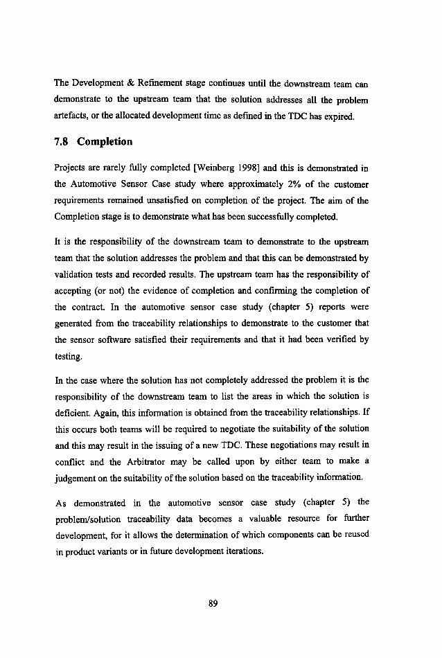
The Development & Refmement stage continues until the downstream team can
demonstrate to the upstream team that the solution addresses all the problem
artefacts, or the allocated development time as defmed in the IDC has expired.
7.8 Completion
Projects are rarely fully completed [Weinberg 1998] and this is demonstrated in
the Automotive Sensor Case study where approximately 2% of the customer
requirements remained unsatisfied on completion of the project. The aim of the
Completion stage is to demonstrate what has been successfully completed.
It is the responsibility of the downstream team to demonstrate to the upstream
team that the solution addresses the problem and that this can be demonstrated by
validation tests and recorded results. The upstream team has the responsibility of
accepting (or not) the evidence of completion and confirming the completion of
the contract. In the automotive sensor case study (chapter 5) reports were
generated from the traceability relationships to demonstrate to the customer that
the sensor software satisfied their requirements and that it had been verified by
testing.
In the case where the solution has not completely addressed the problem it is the
responsibility of the downstream team to list the areas in which the solution is
deficient. Again, this information is obtained from the traceability relationships. If
this occurs both teams will be required to negotiate the suitability of the solution
and this may result in the issuing of a new TDC. These negotiations may result in
conflict and the Arbitrator may be called upon by either team to make a
judgement on the suitability of the solution based on the traceability information.
As demonstrated in the automotive sensor case study (chapter 5) the
problem/solution traceability data becomes a valuable resource for further
development, for it allows the determination of which components can be reused
in product variants or in future development iterations.
89

7.9 Addressing Criticisms
The IDC can be criticised as another form of bureaucracy that will burden hard
pressed engineers further. This criticism can be countered as follows. The IDC
gives a structure to the interaction of related development teams. It was
demonstrated in Chapter 6 that development processes based on a predictive
development model, such as BAE SYSTEMS CEP, often do not define how
related teams should cooperate. The TOC also gives a development context to the
recording of traceability data. The TOC describes how the traceability data is
employed to benefit the development process for example, in change impact
negotiations. The traceability surveys (Chapter 3) demonstrated how a perceived
lack of purpose for the recording of traceability data resulted in the poor recording
and maintenance of traceability data. The TOC creates a customer-developer
relationship between development phases allowing the exploitation of the
upstream team's expertise. This is in contrast to present predictive development
processes where the main contractual relationship is between a team and the
project management. However, the question of whether the IDC adds
bureaucracy to the development process will only be answered by the
implementation of the TOC in a live development environment, which is
discussed in Chapter 10.
7.10 Summary
The TOC addresses the problem of controlling the upstream team bias with
respect to the imposition of changes to a baseline by employing traceability to
provide a basis for communication and the negotiation of change. By employing
traceability in this way, it becomes beneficial to the development engineers and
therefore overcomes the Traceability Benefit Problem. The benefits of the IDC
are further illustrated in Chapter 9 (An Illustration of the TOC) which describes
how the contract would be employed in development of a hypothetical jet trainer.
By making the TOC applicable to each development phase interface progress
90

towards the elusive goal of end-to-end traceability can be achieved. The next
chapter will examine what data structures are required to achieve the aims of the
TDe.
91

92

Chapter 8 TDC Traceability Data Structures
8.1 Introduction ........................................................................................... 93
8.2 Influences of Existing Traceability Structures ...................................... 94
8.3 Influences of Traceability Practice Survey ......................................... 102
8.4 TDC Traceability Data Structures Design .......................................... 103
8.5 Artefact... ............................................................................................. 105
8.6 Artefact Satisfaction ............................................................................ 107
8.7 Artefact Decomposition ...................................................................... 109
8.8 Artefact Validation .............................................................................. III
8.9 TDC Data Structure Summary ............................................................ 113
8.10 Summary ............................................................................................. 113
8.1 Introduction
Chapter 7 outlined the Traceable Development Contract (TDC) and how it
employs traceability as a basis for negotiating changes to a development baseline.
This chapter examines the data structures required to achieve the aims of the
TDC. A number of guiding principles have arisen out of the development of this
thesis, which has influenced the design of TDC Traceability data structures.
• The structures must be generic and applicable to all development phase
boundaries.
• The structures must only record information that is relevant to the TDC and
therefore be able to record information that:
o Demonstrates Problem-Solution satisfaction information
o Allows the navigation of the solution
o Demonstrates solution validation
93
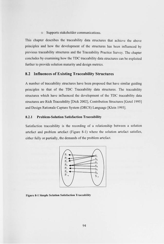
o Supports stakeholder communications.
This chapter describes the traceability data structures that achieve the above
principles and how the development of the structures has been influenced by
previous traceability structures and the Traceability Practice Survey. The chapter
concludes by examining how the TDC traceability data structures can be exploited
further to provide solution maturity and design metrics.
8.2 Influences of Existing Traceability Structures
A number of traceability structures have been proposed that have similar gu iding
principles to that of the TDC Traceability data structures. The traceability
structures which have influenced the development of the TDC traceability data
structures are Rich Traceability [Dick 2002] , Contribution Structures [Gotel 1995]
and Design Rationale Capture System (DRCS) Language [Klein 1993].
8.2.1 Problem-Solution Satisfaction Traceability
Satisfaction traceability is the recording of a relationship between a solution
artefact and problem artefact (Figure 8-1) where the solution artefact satisfies,
either fully or prutially, the demands of the problem artefact.
Figure 8-1 Simple Solution Satisfaction Traceability
94

Satisfaction traceability relationships can be captured in the form of a traceability
matrix or in a hyperlink based tool such as DOORS [DOORS 2007]. These
relationships are of limited use to the engineer, as the presence of a relationship
does not inform the engineer if the solution artefact satisfies the problem artefact
partially, totally or is a part of a collection of artefacts that combine to satisfy the
problem artefact. As a result, the engineer may have difficulty in determining the
impact of a change by just following the satisfaction relationships.
To address these problems, additional domain information is appended to the
satisfaction relationship to allow the engineer to determine the contribution the
artefact makes to the solution (Figure 8-2). This information is referred to as a
satisfaction argument, though it goes by many different names dependant on the
development phase, for example:
• "Requirements Elaboration" for a satisfaction argument that demonstrates how
the system requirements are derived from the user/system specification.
• "Design Justification" for a satisfaction argument that demonstrates how the
design is derived from the requirements.
• "Implementation Strategy" for a satisfaction argument that demonstrates how
the code is derived from the design.
• "Test Strategy" for a satisfaction argument that demonstrates how the tests
exercise the code.
In essence, the above data has the same aim, to present an argument to provide
evidence of how the solution artefact contributes to satisfying the demands of the
problem artefact. This information is normally recorded as plain text, though data
structures have been advanced as a means of describing a satisfaction argument.
95

* Problem Artefact Satisfies
Satisfaction Argument
Solution Artefact
*
Figure 8-2 A Simplified UML Class Diagram of a Satisfaction Relationship
Rich Traceability [Dick 2002] is promoted as a means of providing evidence of
the contribution that a solution artefact makes to the satisfaction of a problem
artefact by recording a satisfaction argument. In Rich Traceability, the satisfaction
relationship is appended with a satisfaction argument expressed in plain text.
Propositional operators are employed to indicate the way solution artefacts
combine to satisfy a problem artefact:
• By conjunction (&) indicating that, the contribution of all the solution
artefacts is necessary for the satisfaction of the problem artefact to hold.
(Figure 8-3)
• By disjunction (OR) indicating that the contribution of anyone of the solution
artefacts is necessary for the satisfaction of the problem artefact to hold.
(Figure 8-3)
Problem Statement
Figure 8-3 Refinement of Solution and Satisfaction Arguments
96
Solution S2.1
Solution S2.2

Rich Traceability allows the engineer to refine his solution by use of refmement
satisfaction arguments. Rich Traceability was successfully employed by Praxis,
for Railtrack in the development of requirements for West Cost Rail Route
modernisation project. Praxis has incorporated extended Rich Traceability into
their REVEAL requirements engineering method [Praxis 2007].
Rich Traceability can be thought of as a member of the collection of Goal
Oriented Requirements Engineering (GORE) methods that also include Goal
Structuring Notation (GSN) [Kelly 1999], Knowledge Acquisition in autOmated
Specification (KAOS) [Darimont et al. 1998] and Goal-Based Requirements
Analysis Method (GBRAM) [Anton 1997]. These methods have similar
taxonomies that consist of a network of goals, which are connected by links. Each
method has its own taxonomy of goals but in essence there are two broad classes
of goals: goals that define the desired characteristic or state of the system and
goals that define how a system characteristic or state will be achieved. Goal links
describe how a sub-goal is related, either positively or negatively, to its parent
goal. Goal links can be combined with combinational operators such as AND/OR.
An alternative to these GORE methods is Problem Frames [Jackson 2001].
Problem Frames represent the problem as collections of sub-problems, each of
which is smaller and simpler than the original. A problem frame defines the shape
of a problem by capturing the characteristics and interconnections of the parts of
the world it is concerned with. This technique employs problem diagrams to
describe the relationships between the machine, the problem domains and the
requirements. A problem diagram (Figure 8-4) shows:
• A dashed oval representing the requirement to bring about certain effects in the problem domains
• Dashed lines representing requirements references
• The Machine that is to be built is represented in bold
97

• The domain rectangles represent the interactions the machine has with the world
/ Problem ... ----------..,,' , Domain A
f I \ , , , ,
Machine
,
~ , ,
, ,
Problem r-- Problem Domain B DomainC
Figure 8-4 A Simple Problem Frame diagram
-Requirement
...... ;r------, , , ,
, , \
Hall [Hall et al 2002] demonstrated how problem frames can be employed in the
iterative development of an architecture and its requirements
8.2.2 Contribution Structures
Gotel [Gotel 1995] proposed the use of traceability structures, known as
Contribution Structures, to improve communications and cooperation between the
stakeholders involved in the elicitation of requirements. Contribution Structures
record the relationship between contributing stakeholders and an evolving
requirement. Contribution structures represent a requirement as an artefact. An
artdact can be a document, model or diagram. Artefacts are classified as being
primitive or composite, which are constituted from further primitive or composite
artefacts. Artefacts are created and maintained by Agents, who are stakeholders
involved in the development of a requirement. There are three classes of Agent: a
principal (P) who established the artefact, an author (A) who expresses the artefact
and a documenter (D) who records or transcribes the artefact. A stakeholder can
98

perform any combination of these agent roles. The principal's responsibility is to
determine and set the artefact's state to approved, pending approval or not
approved. The author's responsibility is to determine how the artefact is related to
other artefacts. The documenter's responsibility is for the physical and
presentational aspects of the artefact. Artefacts are related to each other by one of
two connecting relationships, referencing and adopting. Adopting relationships
represent the following changes to an artefact:
• Copy - use existing information as is with no changes or additions.
• Add - use existing information with extensions to the content
• Remove - use existing information with reduction in content.
• Alter - use exiting information with changes to clarify the content.
Reference relationships provide additional information to improve the
interpretation of the artefact. The combination of these relationships results in a
structure as shown in Figure 8-5.
I_ contribution£P
~--:~~ 0 A
Connectivity :
Artefact
(Adopts) :
Arte~act Contribution 0 Connectivity GJ'8
c-ti,;./'~-----~:~) -..: £ (Adopts),.. COntribUtiOn--' 0 0 A
GJ'8 Figure 8-5 Contribution Structure Relationships: Artefact Evolution
99

8.2.3 Design Rationale Capture System (DRCS) Language.
Klein [Klein 1993] tackled the problem of developing generic data structures,
which would capture the rationale for interdependencies between development
artefacts. His approach was to consider the interdependencies between
developments artefacts to be a result of a number of decisions that are made
during the course of a project. The resulting DRCS language consists of a
vocabulary of assertions consisting of entities such as modules, tasks,
specifications and versions, as well as claims about these entities. The language is
divided into two groups of structures, Synthesis and Evaluation. The Synthesis
structures, Artefact Synthesis (Figure 8-6 Artefact Synthesis) and Plan Synthesis
(Figure 8-7 Plan Synthesis), record the composition of the product and how it
relates the production plan.
Has Submodule
Is a/Type
Iso/Type Iso/Type
Has Allribute
Figure 8-6 Artefact Synthesis
100
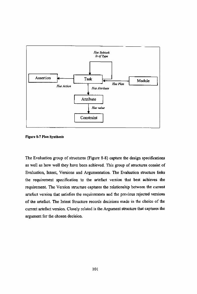
Assertion
Has Action
Figure 8-7 Plan Synthesis
HasSubtask Is of Type
Has Attribute
Module HasP/an
The Evaluation group of structures (Figure 8-8) capture the design specifications
as well as how well they have been achieved. This group of structures consist of
Evaluation, Intent, Versions and Argumentation. The Evaluation structure links
the requirement specification to the artefact version that best achieves the
requirement. The Version structure captures the relationship between the current
artefact version that satisfies the requirements and the previous rejected versions
of the artefact. The Intent Structure records decisions made in the choice of the
current artefact version. Closely related is the Argument structure that captures the
argument for the chosen decision.
101
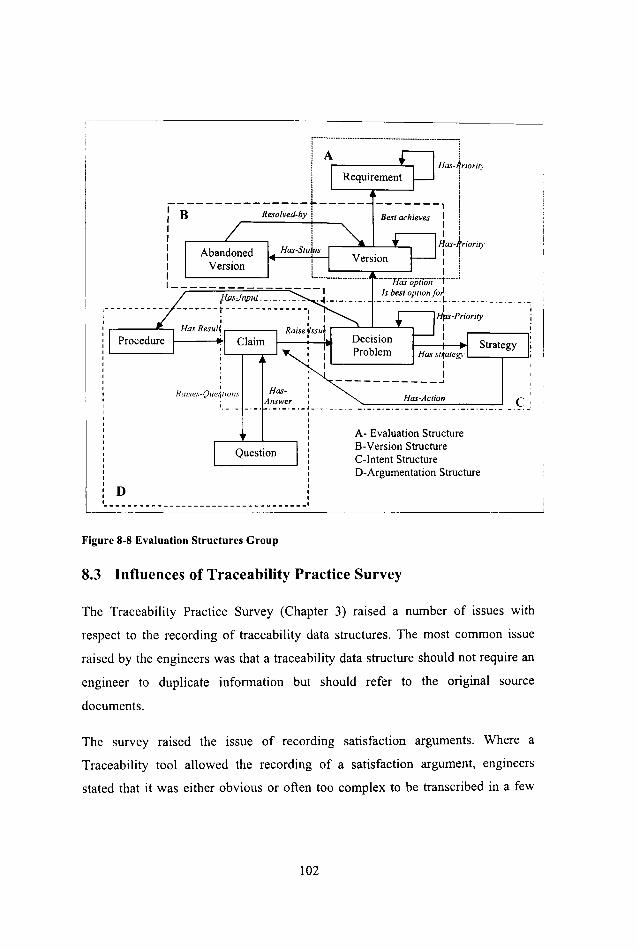
D
r················· .... ····· __ ·_·_·_···_·_-_·_·-l ,
! j I Has-I(riority , !
I I IB--------~:~:;r----- I
! I ! I ! I Has-kriority
I j I I ; I I I .
l_ - - - - t~;;~; _~ _~ _~ _~ _- '~i·:·~·~~···~···~·-·-. ~'~~;;~~:;r~-' _. _. _. _. _. _. _.
I
Raises-Que:ilions Has-Answer
Question
I Hps-Priority
I I
A- Evaluation Structure 8-Version Structure C-I ntent Structure D-Argumentation Structure
Figure 8-8 Evaluation Structures Group
8.3 Influences of Traceability Practice Survey
The Traceability Practice Survey (Chapter 3) raised a number of issues with
respect to the recording of traceability data structures. The most common issue
raised by the engineers was that a traceability data structure should not require an
engineer to duplicate information but should refer to the original source
documents.
The survey raised the issue of recording satisfaction arguments. Where a
Traceability tool allowed the recording of a satisfaction argument, engineers
stated that it was either obvious or often too complex to be transcribed in a few
102

paragraphs and such complex arguments were better described in the project
documentation.
For example, the MBDA ASRAAM project (refer to section 3.5.6) took a
different approach to the recording of satisfaction arguments. These projects did
not try to justify the presence of a traceability relation. They appended the
traceability relationships with data which was relevant to the use it would be put
to. For example, if the primary aim of recording traceability was for impact
analysis, then warnings would be appended to relations indicating the
consequences of a change. This targeted additional information proved to be
popular with engineers.
The survey also highlighted problems when a set of functional derived
requirements was mapped onto an object-oriented design (OOD). Engineers
claimed that it was difficult to determine the correct level of mapping, for a
requirement may be satisfied by the parent object or by one or more of the
inherited objects. The functional requirements to OOD mapping issues were only
partly solved by the adoption of a mapping standard that dictated how
functionality was related the 00 design.
8.4 TDC Traceability Data Structures Design
This section describes how the influences of the previous Traceability data
structures and the Traceability survey have resulted in the following generic
Traceability data structures, which satisfy the guiding principles set out at the
beginning of this chapter.
The key design decision for any traceability structure is whether the structure
should record all the product information or act as an indexing system that
informs the engineer of the location of the relevant information. There are
advantages and disadvantages to both approaches.
103

8.4.1 Design Decisions
The Automotive Sensor project (Chapter 5) was unique among the surveyed
projects as it was the only project which recorded all project information in its
traceability system. This approach had a number of advantages. For example, data
was not duplicated and there was no need to maintain external references. This
enabled up-to-date and consistent project documents to be generated from the
project data contained in the traceability system. The main disadvantage of this
system was the restricted set of tools that could interface with the DOORS tool.
Researchers have tried to address this problem of data sharing between tools by
developing traceability repositories that interface with a wide range of
development tools. The AP233 application protocol data model [Herzog 2000] is
an example of a data model for such a traceability repository. Another example of
a traceability data exchange model is the Meta-Modelling Approach to
Traceability for Avionics (MATra) [Mason 1999]. Unfortunately, the success of
these data exchange models or repositories have been limited due to complicated
data conversion required to support a limited range of development tools.
For the remainder of the surveyed projects their traceability systems contained a
mixture of internal data and references to external data and the application
required to manipulate this data. Though this approach has the inherent problem
of maintaining external references, it does not restrict the use of development
tools. As it is not possible to restrict or even to specify the tools required for all
developments phases, the TDC traceability structures adopt the approach of
recording references to external data sources and the location of the application
required to manipulate the data. This approach of referencing is compatible with
the developing XML technologies, such as XLink [Xlink 2007], which allow links
to be created between diverse range of media artefacts. The XML Linking
Language (XLink) allows elements to be inserted into XML documents in order to
create and describe links between resources. It uses XML syntax to create
104

structures that can describe the simple unidirectional hyperlinks of today's HTML,
as well as links that are more sophisticated. The Xlink standards and related tools
are presently under development.
The TDC traceability structures are required to be applicable to all development
phases. This requirement gives rise to the idea of a "generic artefact" which can
be decomposed as required into further artefacts. The "generic artefact" is the
basic building block of the TDC traceability data structures. Problem and Solution
Artefacts are generalisations of this common development artefact (Figure 8-9).
Decom osition:
Artefact
Description: Artefact Location: Application: Development Status: {Not Agreed I Agreed I Deferred}
Figure 8-9 Problem & Solution Generalisation of a Common Artefact (UML Class Diagram)
Finally, the previous influences and the original guiding principles (refer to 8.1)
have given rise to four basic data structures, Artefact, Artefact Satisfaction,
Artefact Decomposition and Artefact Validation.
8.5 Artefact
The aim of the Artefact data structure (Figure 8-10) is to support the Problem
Discourse and Development & Refinement stages of the TDC. In the Problem
105

Discourse stage, the Artefact structure aims to support the clarification of issues
with the problem artefacts and to record the agreement of downstream developer
team that these artefacts are suitable for the production of an initial solution. This
is achieved by recording the queries and related replies raised on each artefact and
their agreed development status. The Development Status attribute records the
state of agreement between the two teams on the suitability of the artefact for the
production of a solution. The artefact can have a Development Status of not
agreed, agreed or deferred.
Prevlolls Version
Change Change
UID# ------- Description I Type: {Copy I Add I RemovelAherl
Arteract . I .
UID#: Description:
~ ~ Change Authority Location: I
Application: Development Status: {Not • Technical Agreed I Agreed I Dererred I I Authority
Role: Authority I . Tech.
Authority Challge -' IL
I~ Implementation Implementer
Artefac Implementer Query Role: Implementer
I , • Query
I UID# Text:
I \Z Query Raised by
Stakeholder Reply .... ,.
UJD# ,~ I I Name ... Email
Query Reply I Rep/iedby I
Telephone QueryUID# Location Address
Text:
Figure 8-10 Artefact Structure (UML Class Diagram)
106

In the Development & Refinement stage, the Artefact structure supports the
recording of changes to problem or solution artefacts. This information would be
recorded by two separate structures, problem artefact changes and solution
artefact changes, both of which are instantiations of the generic Artefact structure.
Development artefacts have stakeholders who are interested in the development
and maintenance of the artefact. From the survey, there appear to be two classes
of stakeholder, the Technical Authority and the Implementer. The Technical
Authority is normally an engineer who has the responsibility of overseeing the
production, and the approval of the artefact. This stakeholder plays a similar role
to that of Gotel' s Principal Agent. The Implementer can be a number of engineers
who are or have been involved in the production and maintenance of the artefact.
Again, the role of this stakeholder is similar to the combined roles of Author and
Documenter Agents proposed by Gote!. The changes that are allowed to be made
to an artefact draw upon Gotel's Adopting Relation. A change to an artefact can
be a Copy, Add, Remove or Alter just as with Gotel's relation.
8.6 Artefact Satisfaction
The Artefact Satisfaction structure (Figure 8-11) lies at the heart of the TOC and
can be thought of as the core traceability structure. The purpose of this structure is
to record the relationship between problem and solution artefacts. This
information is employed throughout the TDC:
• In the Proposed Solution stage of the TDC to demonstrate the coverage of the
initial solution.
• In the Refinement stage of the TDC to determine which solution artefacts are
affected by changes to problem artefacts and vice versa.
• In the Completion stage of the TDC to demonstrate the coverage of the final
solution and how it will be validated.
107

As Dick [Dick 2002] stated, the simple recording of problem solution
relationships may provide limited information and a satisfaction argument may be
required to describe the contribution the solution artefact makes to the satisfaction
of the problem. In practice, engineers found the writing of such arguments
difficult. Dick suggests that this may be a reflection of the lack of understanding
of the underlying relationships. The survey implies that there is a trade-off
between the effort expended in writing such an argument and the clarity it brings
to the interpretation of the problem-solution relationship. However, for complex
or rigorous transformations a satisfaction argument is required and GORE
techniques such as Rich Traceability provide a suitable method of describing such
an argument. Therefore, the Artefact Satisfaction structure has an associated class,
a Satisfaction Argument, which refers to a solution argument describing how the
solution contributes to satisfying demands of the problem artefact.
Arter.,,. (problem) UID#: Deacriplion: Location: Application: Status:
Artefact (Solution)
UlIlt: Sa/b/acllo" Dcacription:
1-----.-----1 Lo<ation:
Satisfaction Argument
UID#: Reference to GORE Araument ·Rich Traceability
• Application: Status:
Figure 8-11 Artefact Satisfaction (UML Class Diagram)
The Artefact Satisfaction structure (Figure 8-11) is a many to many relationship,
such relationships are often difficult to comprehend. Therefore, the Artefact
structure can be thought as a composition of two simpler, one to many,
108

relationships: Satisfaction-Problem View and Satisfaction-Solution View (Figure
8-12.)
Arterac' (problem)
UlD#: Description: Location: Application: StatUi:
Artefact (Problem)
UID#: DClcription: Location: Application: StatUI:
Arter ... (SoluUoo) UlD#:
Sa,i6/oeJio .. Problnn View Deoc:riptioo:
r-------~------~ ~ • Application:
Sati.faction Argument
UID#: Rere~nce to GORE Arpunmt ·Rich Traceability
Sali6/action-Sollltion Yin.'
Sati.faction Araument
UID~: Reference to GORE Argument -Rich Traceability
S ..... :
Al1CflCt (Solution)
UlD#: Delcription: Location: Application: SIalUI:
Figure 8-12 Artefact Satisfaction: Problem and Solution Views (UML Class Diagram)
These two relationships represent the view of each team. The upstream team will
be mainly concerned with the problem view, while the downstream team will be
concerned with the solution view.
8.7 Artefact Decomposition
The aim of the Artefact Decomposition structure (Figure 8-13) is to allow the
engineer to describe the compositional relationships between artefacts that
combine to form the problem or the solution. The degree of decomposition is a
109

practical issue. Fine granularity gives rise to a large number of artefacts, which in
tum results in high data entry and maintenance burdens. The indications, drawing
upon the traceability survey (Chapter 3) and the automotive case study (Chapter
5), are that 200-300 artefacts seems to be the maximum number that a small team
(of up to 5 people - 50 to 60 objects per person) can handle comfortably.
Interface UID#: De.cription
AllribUle
, . Attribute
UID#: Name Type
0.0
-" "' Inteiface 1
Constraint
\ 1
Constraint UID#: Limits
Artefact UID#: Description: Location: Application: Status:
Decomposition:
Demain Information
WamingText:
Figure 8-13 Artefact Decomposition (UML Class Diagram)
The Artefact Decomposition structure takes a similar approach to Klein's Artefact
Synthesis structure. The method of decomposition, e.g. functional or object
orientated is not recorded, only that there is a logical decomposition relationship
between artefacts.
The aim of the TDe data structures is to provide information to allow the
negotiation of change. Both Klein and the traceability practice survey highlighted
110

the importance of being able to detennine the impact of a change on interfaces
exhibited by an artefact. Similar to Klein's Artefact Synthesis structure the
interfaces exhibited by the artefact are recorded in Artefact Decomposition
structure. For each interface, the attributes of the interface and their constraints are
also recorded.
Making changes to solution artefacts' relationships may produce unwanted
effects. Unwanted effects related to the non-functional aspects of the system, such
as memory usage, timing and security are difficult to determine without domain
knowledge. The engineers at MBDA tackled this problem by tagging solution
artefacts with known non-functional problems with "change warning" notes.
These notes were informal warnings aimed at other engineers who may not have
an in-depth knowledge of the domain about the problems that may occur if an
artefact was changed.
As a result, the Artefact Decomposition structure has an associated class, Domain
Information, which will allow the recording of domain information to aid the
interpretation of the traceability data.
8.8 Artefact Validation
The Artefact Validation (Figure 8-14) structure records how an artefact will be
validated. This structure aims to support the Proposed Solution, Development and
Completion stages of the TDC. In these stages, it is the responsibility of the
downstream team to be able to demonstrate how they intend to validate their
solution.
The approach adopted in the automotive sensor case study (Chapter 5) was the
decomposition test descriptions. In this case study test concepts described the
testing at a high level. Test concepts were decomposed into test procedures which
were in turn decomposed into test case and test steps. Individual test cases and
steps were reused across a number of test procedures.
111

Artefact (Problem) Artefact (Solution) UJD#:
" A11eflJet SIlIi8/lICIiD" UJD#: Deocription: Description: Location: " Location: Application: Application: Status:
" Status:
" " Problem Tech Authority Tesler YalldDliDn
I I ill Tecbnical Authority Tester Validation
(Problem) Role: Tester Method Role: Authority - UJD# Te.t Acceptance Description
I I I
~ Test
0·"
Stakeholder Test Deocription Test Result
Name UID# ~ U/D# UID# Description I Description Bmail Resul,. Locstion Telephone Location Address
Figure 8-14 Artefact Validation (UML Class Diagram)
The Artefact Validation structure records two levels of test decomposition, a
Validation Method that is a high-level description of the required testing and Test
Descriptions which define individual tests. Validation Method will address a
number of artefacts and Test Descriptions can be reused by a number of
Validation Methods.
As the contract progresses to completion, it is the responsibility of the
downstream team to demonstrate the solution has been adequately tested. The
upstream team has the responsibility of accepting, or not, the validity of the
testing. The Artefact Validation structure records the upstream stakeholder who is
responsible for accepting the validity of the testing.
112

8.9 TDC Data Structure Summary
Traceable Development Contract (TDC) data structures are a refinement of
existing traceability data structures. The structures have been kept simple and
generic so enabling the TOC to be applied across number of development
boundaries. These data structures can be considered the basic building blocks that
can be extended as the development environment demands. The data structures
are similar to structures that are already commonly employed. For example, many
of the attributes of the Artefact structure will be found in configuration control
data structures. This means that existing tools, such as DOORS, Commercial
Relational Data Bases and PVCS, can be employed to implement the contract.
Appendix B describes relational schema for an example implementation of the
structures.
A criticism that can be made of previous traceability structures is that they lacked
a development context: when should the structures be populated, by whom and
how should the traceability data be employed in the development process. The
Traceable Development Contract protocol (Chapter 7) provides a context to these
structures by stating who will populate the structures and how the data will be
employed to benefit the local development process. In this way, the TDC protocol
brings a purpose to these traceability data structures.
8.10 Summary
Traceable Development Contract (TDC) data structures are a refinement of
existing traceability data structures. The structures have been kept simple and
generic so enabling the TDC to be applied to any development interface. These
structures can be considered the basic building blocks that can be extended as the
development environment demands. These simple structures work in conjunction
with the TDC stages to provide information that aids the negotiation of change to
113

development baseline artefacts; they also provide additional information on the
maturity of the solution.
Having described the data structures and the IDC protocol (Chapter 7), the next
chapter illustrates how they could be employed in the development of software for
a hypothetical jet trainer.
114

Chapter 9 An Illustration of the TDC
9.1 Introduction......................................................................................... 115
9.2 Background: Accipiter 300 ................................................................. 116
9.3 Initiation .............................................................................................. 119
9.4 Problem Discourse .............................................................................. 122
9.5 Proposed Solution ............................................................................... 127
9.6 Development & Refinement ............................................................... 134
9.7 Completion .......................................................................................... 138
9.8 Summary ............................................................................................. 140
9.1 Introduction
Chapter 7 outlined the TDC protocol and Chapter 8 described the data structures
required to support the contract. This chapter builds upon this work by describing
how a contract may work in practice. To illustrate the TDC, and the complexity of
the aerospace industry, this chapter will consider the development of the Mission
Planning System software for a hypothetical Jet trainer. The illustration is not a
proof or a validation of the TDC, it is presented here as a means of exemplifying
the ideas presented the previous chapters.
The Mission Planning System is composed of two parts, the aircraft's mission
computer and a land-based mission planning system. Each part is specified by a
common requirements team, though the software is developed by two different
teams. This chapter outlines how the requirements team and software design team,
which are developing software for the aircraft, would work according to the IDC
and how they would employ the traceability structures. These working practices
are compared and contrasted with the relationship the requirements team has with
lIS

the land-based software development team that employs a traditional method of
communications: issuing interface documents and holding review meetings.
9.2 Background: Accipiter 300
The hypothetical Accipiter 300 is the latest of a series of jet trainers produced by
the (fictional) British Aircraft Corporation (BAC). This aircraft has a facility that
allows the pilot to load a flight-plan into the aircraft's mission computer. In flight,
the aircraft's mission computer employs this information in conjunction with
information from its positional sensors (Figure 9-1) to overlay mission related
information on the pilot's displays.
Altimeter
Figure 9-1 Positional Sensors
9.2.1 Mission Planning System
The Mission Planning System for the Accipiter consists of two parts: the aircraft's
mission computer and a land-based mission planning system. The land-based
mission planning system allows the pilot to create and store his flight-plan in the
form of a series of navigational reference points, known as waypoints. The flight
plan is transferred to the aircraft's mission computer via a 4mm tape data
cartridge.
116

The Accipiter's mission computer reads the data cartridge before flight, checks
the validity of the data and stores the resulting flight-plan. In flight, the mission
computer employs the flight-plan information in conjunction with information
from the aircraft's positional sensors to overlay mission related information on the
pilot's displays. During flight, the mission computer stores information from the
aircraft's positional sensors (Figure 9-1) so that the flight can be recreated on the
land-based mission planning system.
9.2.2 Development Organisation
The development of the Mission Planning System is spread across the UK. The
elicitation and control of the requirements for the Mission Planning System is
performed by the main contractor, BAC, based in the North West of England. The
software for the aircraft's mission computer is developed by a subsidiary of BAC
based in the South West and the hardware by a subsidiary based in the East of
England. The hardware and software for the land-based mission planning system
are produced by a separate company, FET Systems, based on the south coast of
England.
9.2.3 Scope of Illustration
This illustration will consider how traceability can employed in the development
of the aircraft's mission computer. This illustration considers the implementation
of an upgrade that occurs after the initial release of the requirements.
The change in functionality is that a Secure Digital (SO) High Capacity (HC) non
volatile memory card will replace tape data cartridges for the transfer of flight
data between the aircraft and the land based planning system. The SO card will act
as a virtual hard disk and there will be no requirement to validate the data held on
the card.
117

9.2.4 Use of Traceability
The BAC South West software team employs a traceability tool to record the
relationships between the requirements, software design, code and validation tests.
The BAC South West software team has an archive of traceability relationships
for the previous versions of the mission computer. The FET Systems software
team does not employ a specific traceability tool, though they do employ a
spreadsheet tool to demonstrate their test coverage.
9.2.5 The Introduction of the TDC
For the development of the next version of the aircraft's mission computer
software, the requirements team (BAC North West) and the software design team
(BAC South West), agree to work according to the TDC: the requirements team
acting as the upstream team and the software development team acting as the
downstream team. Both teams agree to a shared file system to store shared
artefacts and a traceability database that has a schema (described in Appendix B)
that implements the traceability structures described in Chapter 8.
The following sections will work through the TOC protocol stages (Section 7.3).
• In the Contract Initiation stage (Section 9.3), the terms of the work that is to
be undertaken are defined.
• In the Problem Discourse stage (Section 9.4), both teams clarify and agreed
the problem artefacts.
• In the Proposed Solution stage (Section 9.5), the BAC South West software
team demonstrates to the BAC North West requirements team how they intend
to tackle the problem.
• In the Development and Refinement stage (Section 9.6), BAC South West
software team produces and refines the solution.
118

• In the Completion stage (Section 9.7), the BAC South West software team
demonstrates to the BAC North West requirements team that they have
satisfied the contract.
For each stage, the working practices of the BAC requirements team and the BAC
software team will be compared with the working practices of the BAC
requirements team and FET Systems.
9.3 Initiation
The Initiation stage is concerned with defining the contractual terms of the work
that is to be undertaken. The information that is required to be recorded and
agreed at this stage of the contract is described in Table 3.
I Activity The production of the Accipiter 300 mission computer Description software.
2 Stakeholders Upstream Team: members of the requirements team (BAC North West) (Figure 9-4) Downstream Team: members of the mission computer software development team (BAC South West). (Figure 9-4)
3 Problem The aircraft mission computer software requirements and Artefacts UML Use Case Diagrams (refer to section 9.3.1)
4 Planning Delivery dates and milestones for the mission computer software. (Refer to Figure 9-3 Mission Computer Development Plan.)
5 Arbitration The Chief Engineer for Accipiter 300 is identified as the Procedure arbitrator for any disputes. Teams are required to describe
their position with respect to any conflict. Teams are required to present information, such as an impact analysis, that supports their position. Team are required to offer possible solutions to the conflict.
Table 3 TDe Initiation Information
9.3.1 Example Mission Computer Problem Artefacts
The following are examples of the problem artefacts which are required at
contract initiation. For example, Tape Interface Requirements (Table 4), UML
119

Use Case (Figure 9-2), Delivery Plan (Figure 9-3) and Stakeholder Organisation
Charts (Figure 9-4).
Unique Tape Interface Requirements ID
10 Before Flight: Flight Plan Down Load and PDC Cartridge Insert 10.1 The Pilot will insert the Flight Plan Data 4mm tape cartridge
into the mission computer. 10.2 The Pilot will select from the mission computer touch screen
the Download Flight Plan option 10.3 The Mission Computer will detect the presence of a correctly
formatted Flight Plan tape cartridge. (For the format of Flight Plan tape cartridge refer to Appendix G: Data Formats)
10.4 If a Flight Plan tape is not present or not of the correct format then the Mission Computer will display - "Download Aborted" and will eject the tape cartridge ifpresent.
10.5 The Mission Computer will read and validate each waypoint from the tape. Writing the contents of each way point to FlightPlan.dat data file (For the format of FlightPlan.dat refer to Appendix G: Data Formats)
10.6 If a waypoint is corrupt or the total number of waypoints does not agree with the number in the taper header then the Mission Computer will display - "Download Aborted" and will eject the tape cartridge.
10.7 The Mission Computer will display - "Download Successful" once the FlightPlan.dat file has been written to the hard disk.
10.8 The Mission Computer will eject the Flight Plan data tape cartridge.
10.9 The Pilot will insert a blank formatted tape data cartridge, for the recording of the aircraft's positional data, into the Mission Computer.
10.10 The Pilot will select - "Insert PDC" PDC - Positional Data Cartridge.
10.11 The Mission Computer will detect the presence of a correctly formatted Positional Data 4mm tape cartridge. (For the format of Flight Plan tape cartridge refer to Appendix G: Data Formats)
10.12 If a Positional Data tape is not present or not of the correct format then the Mission Computer will display - "PDC Insert Failed" and will eject the tape cartridge if present.
10.13 On the successful insertion the Mission Computer will display - "PDC Inserted"
Table 4 Requirements
120
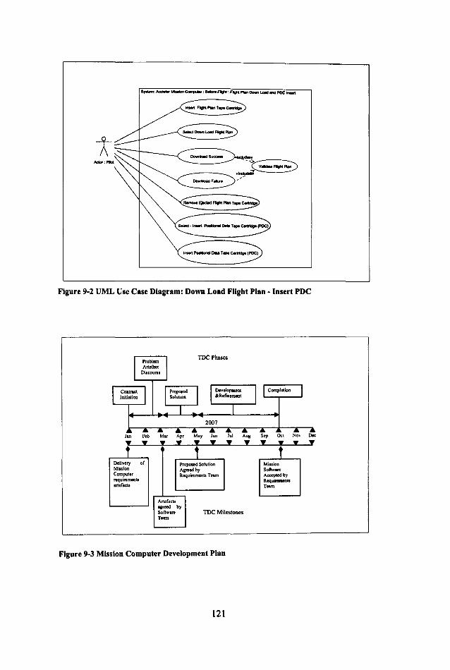
Figure 9-2 UML Use Case Diagram: Down Load FUght Plan - Insert PDC
Jan Feb Mar Apr May Jun Jul Aug Sep Oct No\' Oct .................. f , T
Delivery of Proposed Solution Mission Mission Agreed by Sol\ware Computor Requirements Team Accepted by requirements Reqwn:mertts .nefac'. Team
Artefacts agreed by SoRware TDC Milestones Team
Figure 9-3 Mission Computer Development Plan
121

BACNortb W ... Minion Computer Tape In ........
Requiremenll Team I BACSoudIWcot Miui ... Com ......
m........ SoJlwar< Team
T .... Leod Jam. Browne
Jameo.Browne2@BAC . ..., 01904433383
SAC Aerodrome, Cumbria.
T .... lad Paul~
[email protected] 01904633985
BACSOftw .... Somonct
I Rcquirernenll AnaJ)'It Requiremenll Anal),.t
James Walker Andrew AdamJ James, [email protected] [email protected]
1 Developei' DovcJopcr
Henry Anderson ADdmo AnDIIroa& [email protected] ADdmo.Anns1ruoIJ@lJAC .....
01904633984 01904633986 01904433384 01904433385 SAC MiNion Software SAC Mi.uion SoftwaR"
SAC Aerodrome, Cumbria. SAC Aerodrome. Cumbria, SOmenet. Som ......
Figure 9-4 Organization Chart
9.3.2 Comparing and Contrasting with FET Systems' Approach
At the start of the project, the FET Systems software team will have established
the activity description (1), problem artefacts (3) and planning information.
However, FET Systems software team will not have identified all the relevant
stakeholders (2) and a method of arbitration (5). From the observation made
during the traceability survey, none of the development processes considered the
problem of conflict between teams. For these development processes, there was
no requirement to define an arbitration process and this is the case for FET
Systems. It was also observed that in many cases personal contact between teams
was often limited to team leaders. Failing to identify a method of arbitration may
result in the poor resolution of inter-team conflicts. Also by failing to establish all
stakeholders, the efficiency of communications between the two teams will be
reduced.
9.4 Problem Discourse
The Problem Discourse stage aims to clarify any issues with the problem artefacts
and to obtain the agreement of the downstream developer team that the artefacts
122

are suitable for the production of an initial solution. It is at this stage, that the
SAC requirements team start to populate the traceability structures. The fust
structure to be populated is the logical decomposition structure (Section 8.7). This
involves identifying all the artefacts and recording their decomposi tion. The
logical decomposition structure acts as an index to the problem artefacts, allowing
the engineers to navigate the composition of the problem. A suitable method of
decomposing the Accipiter's requirements would be to decompose according to
the parent document structure. In this case, each requirement statement would
become an artefact. For example, Figure 9-5 represents the decomposition of the
Accipiter's textual requirements.
Rcquiremenl$
UID# I Description: Mission Computet - Flight Modc=s Development S latus : No t Agreed
Requirements
UID# IO Description: Pre FliSlu Development SU\ lus: Not Agreed
Requirement
UIOff IO.1
Requirement
UIDNI I Description In Fl ight Mode De velopment Stalus : Not Agreed
Requm::ments
UIO#12 ~scnplion : Fhght Complete lk"c:lopment Status: Not Agreed
UIO# IO.2
Requirenu:nt ~~-------- ~------~ V UIO#IO.l
• __ ... _ ' ___ ...r.I .. ______ _
I Requirement : I ----------------. I
- - - ~ UJDN... : ,f'-.................. = ....... -----'------, I R«ju;rement ,
UID#IO.1l Description: On the success ful insertion the Miss ion Computer will displny - "POC Inserted" De velopme nt Slnhl.~ : Not Agn-ed
Further dccompo cd requirements
Figure 9-5 Logical Decomposition of the Accipiter Requirements
123

Each artefact has a development status (Not Agreed, Agreed or Deferred) that
records the state of agreement between the two teams on the suitability of artefact
for the production of solution.
The second structure to be populated is the Artefact structure (refer to section 8.9).
This structure records the ownership and development history for each artefact.
For example, Figure 9-6 show how the Artefact structure is applied to textual
requirement 10.13. These traceability structures allow queries to be performed
that help the BAC software team determine the suitability of the requirements.
I UID~S4 Chonge
Change Implemenler --, Chonae ,
UIDNSS ,
I>eac:riplion "POIitional Data Canridp" - , Chang. Authority
, Type: AI.er , , ,
I
J UIDNIO.U
I Requiremall ,
I , , Stakeholder: Authority
I ,
UID#12 Authority Requiremcot ,
L....t Name James Browne l7---rl EmaiUamee.Browne2@BAC,com
~ Requirement T.I.phoneOI904433383
~~----j Address BAC Aerodrome, Cumbria. UID#10.13 Description: On the successful illlCrtion the Million Computer will dilplay - "PDC t-- P,.,,/o",
Stakeholder: Implementer InJertcd" Vers;OIU Development StatUi: Not Aareed
UID#13 .. Name Andrew AdlU1ll Email Androw.AdlU1ll@BAC,com Implem.nter F T.I.phon.01904433383 t-Addreal BAC Aerodrome, Cumbria. Art./act Qu.ry Stakeholder
UID.S6
Query y Name Andrew AnnItrona EorWI AndRw._ .. @BAC.com
UID#IOO T.lephone 01904633986 Text:What is PDel Address BAC Mission Software. Somcnet.
Repll.dBy Art./act Reply ~~ Raised By
Query Reply
Query UID#120 I Text: POC "Positional Dala CartridRe
Figure 9-6 Artefact Structure for Requirement 10.13
124

The queries fall into three groups,
• Information Oueries: This group of queries involve the determination of the
requirement and its attributes, such as the implementer (or in this case the
writer) of the requirement and the technical authority for the requirement.
(Example queries can be found in Appendix C.)
• Dialog Oueries: This group of queries involves creation and recording of
dialog between the two teams with respect to issues related to the requirement.
(Example queries can be found in Appendix C.)
• Status Queries: This group of queries involve the determination and setting of
the development status of a requirement. (Example queries can be found in
Appendix C.)
As requirements are normally specified in text, they can be recorded in the
description attribute of the artefact structure. Where a requirement is specified by
a drawing or a diagram, the description attribute will describe the diagram and the
location attribute will record the location of the diagram. This approach was
adopted by many of the projects in the traceability survey.
As stated in section 8.5 the Artefact structure is derived from Gotel's
Contributions Structures. Gotel claimed the following benefits from the
implementation of such structures in a development environment:
Artefact Ownership, Commitment and Responsibility: The Artefact structure
defines ownership (Technical Authority and Implementer). This impels these
stakeholders to commit to a position on the development state of an artefact The
result of this commitment is that the responsible stakeholder would take a position
and engage in discussions with respect to changes to an artefact. In this
illustration, the BAC requirements team members are committed to being a
technical authority or implementer of the Accipiter's requirements.
125

Artefact Contribution: The ability to record the contribution made by each
stakeholder to an artefact is found to aid change discussions and allows project
managers to track progress and allocate artefact ownership. The Artefact structure
records the original implementer and any changes made. For each change to an
artefact, the Artefact structure records the stakeholder who contributed. In this
illustration, the Artefact structure will record the changes the BAC requirements
team members make to requirement artefacts.
Uncovering Hidden Details and Undocumented Events: The use of traceability
structures often results in the uncovering of hidden artefact details and
misunderstandings between stakeholders. The Artefact structure allows the
recording of queries and replies for each artefact. In this illustration, this feature
can be employed by the BAC software team asking questions of the requirements
and the BAC requirements team replying to those queries.
Agreement: The use of traceability structures help stakeholders to come to an
agreement with respect to the development status of an artefact. Each Artefact has
an attribute that records the agreed development status. In this illustration, the
development status attribute is employed to demonstrate which artefacts the BAC
software team have agreed to be suitable for development.
9.4.1 Comparing and Contrasting with FET Systems' Approach
On reading the requirements, the FET Systems software engineers will have
similar questions on the new functionality to that of the BAC software team. The
FET Systems software team takes a traditional approach, collecting its questions,
and arranging a requirements' review meeting with the BAC requirements team to
obtain clarification. By failing to identify all the relevant stakeholders, the FET
software engineers may target their questions at the wrong engineer. This is in
contrast to the use of the traceability database that allows the targeting of
questions to the correct stakeholder. Such a shared traceability database may even
mitigate the need for a review meeting. Given the distances between development
126

sites, this would reduce development costs. However, if a review meeting is
required then the output from the traceability database, such as the raised queries
and answers, will help in the review of the requirements.
9.5 Proposed Solution
The Proposed Solution stage starts once all the problem artefacts, the
requirements, have been agreed or deferred to later release. This stage allows the
BAC software team to demonstrate how their prototype design will address the
requirements.
Software designs are commonly described using diagrams such as UML package
or deployment diagrams (for example, Figure 9-7 and Figure 9-8 ). Diagrams
cannot be decomposed in the same way that the textual requirements were
decomposed in the previous phase.
IM_~I
Tn!ce R.fO{A •
Figure 9-7 Prototype Package Decomposition
127

.execution environment. Mission Computer
[] Ink
Figure 9-8 Prototype Deployment Diagram
Artefacts in the diagrams are identified by marking them with unique id, for
example in Figure 9-7 each package is marked with an identifier. In the case of
diagrams, the Artefact Decomposition structure becomes a flat structure that lists
the artefacts described in the diagram (Figure 9-9). To determine the true
relationship between artefacts the engineer will be required to refer to the original
diagram.
128

Design Artefact: Decomposition Diagram UIDfI:Dl.O Deocription: Mi"ion Computer Deployment
,....- Location IIAccI3OO1DesIMiJ,ion]aok _ UML.uxf Application: Umlet Statui: Not Agreed
f Design Artefact: Decomposition Diagram .,
UID#:Dl.l
....---. o...ripti~?: Sheduler
A DeBiS!! Artefact: Decoml!!!sition DiaS!!!!! S UID#:DI.2
Descriotion: User Interface Lo Design Artefact: Decomposition Diagram
.\ ~~ U1D#:D1.3 Description: Display Waypoint L
L...;.. A Design Artefact: Decomposition Diagram _\ S U1D#:D1.4
Description: Tape Package
~ Design Artefact: Decomposition Diagram SI UlD#:D1.S
Description: Read SCDlor
L.;;E l.e<ation IIAccl300lDesIMiuion_ Pock _ UML.uxf Application: Umlet Statui: Not Agreed
Figure 9-9 Artefact Decomposition - Package Diagram
Once the design artefacts have been identified, the Artefact structure is populated
for each design artefact. In the same way as the requirements artefacts, the design
artefact structures records the ownership and development history for each design
artefact.
To demonstrate how the prototype design will address the requirements, the BAC
software design team populates the Artefact Satisfaction structure (refer to Section
8.6), recording the relationships between the requirements and design artefacts. In
the cases where it is not clear what contribution a design artefact makes to the
satisfaction of a requirement (or a collection of requirements), a satisfaction
argument may be required. In this illustration, the BAC software team have
written a document (Mission Computer Architecture) that outlines the reasoning
behind the design. The Mission Computer Architecture document describes the
129

engineering reasoning for the design, the decomposition of the functional
components that comprise the design and a detailed description of the
functionality of each design component. For design components that are safety
critical the component textual descriptions are supplemented with a GSN
argument (refer to 8.2.1). In this example, the requirements-tape package
traceability links have an associated trace to the sections of the Mission Computer
Architecture document that describe the tape interface (Figure 9-10) .
Requirement
Design Artefact: Decomposition Diagnm JlCIquirement
r==~;;~=5~==::3~::::~J U10fI:01.4 Description: Tape Pac"''' Requirement Loc.tion IIAe<:I3OOIDesIMiuion Pad UMLwr,(
Application: Urnh:t --
Reqwremenl
Rcquirement
UIDNIO.13 Doaerlptlon: On the successful insertion the Mission Computer will di.play - "POC In.erted"
Slalul: Not Agreed
UIDHSAI DolCription: t.ililion Computer Architecture Location /I Accl300/Des/ M .... ion COqNleI' Design StratelY.doc
Figure 9-10 Artefact Satisfaction: Requirements and Tape Package
The TDC requirement that the BAC software team be able to demonstrate the
validity of the design will entail the population of the Artefact Validation structure
(refer to section 8.8) for the design artefacts (Figure 9-11). The design Artefact
Validation structure records how each design artefact is to be tested.
Also at this point that the BAC software team start to write code. As with the
requirement and design artefacts, the code is described by artefact decomposition
and artefact structures. Artefact Satisfaction structures are employed to record the
relationship between the design and code artefacts. In this case, it is a simple one
to one relationship between code and UML package (Figure 9-11).
130

I~-~ SaJ/sjlu
II ~i""",' Lor.. o..ip _: Dt:compoaitilRl 0;. .....
UID#:DIA Coclo Arl<fact
Dfteriplion: Tape ln1<rface Package ~ UID#:C1.6
Locationi/Aecl3OO1Dea1Miuion Pad< UML.w<f DacripIion: Tape _ .... Pocb&e
Requir.mmt ~-~ Awlicalion: Umlct -- LocatiooIIAco:I3OOICodefTapePocb&e .•
RoquiMmcRt 1 Yallda/ion
UlDHIO.13 inaertion the
Validation Method ValiditiouTCSII
~ UlD#:V2.0 Tu/
V.IIA •• : :-:;:: OeKription: Tape InterfacePackage Validation Method N VllidotiooT_ Locationl/Ac:cI)OOIT •• tlTapo]odIall'_ VIl_Modtod.dac Application: MS Word UID#:TSO
I Dfteription: Tape Pocb&e Tal
Au/horfty 1RUUfIS .. • Tu'e,.
Stakeholder: Te.l Authority Stalcelt.lder:Teo .... UIDHI3 UlDHS6 I ValicWion Tell ReIuJb
~ Name Andrew Adam, Name Andrew ArmItrong v.,...·::-.;; :-;; Bmail [email protected] Email [email protected] Telephone 0190443)383 Telephone 01904633986 Validation Tesu R.uh.
AddreH BAC Aerodrome, Cumbria. Addreu BAC Million Software, Sommet. y UID#:TRSO DelCription: Tape Tat Resuhl Location:l/AccI3OO1VALl1RES1 .. -- .
Figure 9-11 Artefact Validation: Tape Package
In this illustration, an assumption (9.2.4) was made that the BAC software team
had employed a traceability tool to record the relationships between the
requirements, software design, code and validation tests for previous products.
This assumption has been made to allow the demonstration of the benefits that can
be achieved from traceability when developing product families. The weakness of
this assumption will be considered in the next section.
The Automotive Sensor case study (Chapter 5) demonstrated the benefits in the
use of traceability in the selection of a base product for the development of a new
product. For the production of a new sensor, the new requirements were compared
against the exiting products to determine which sensor would be a suitable base
product. This use of traceability enabled the software engineers to reuse existing
software and tests, thereby reducing their workload.
The selection of a base product is a complex process, as the engineers have to take
into account the issues relating to the removal and addition of functionality.
However, the TDC traceability structures can aid the process. Having the
131

requirements recorded in the Artefact Decomposition structure allows them to be
compared with the requirements, held in the same structures, for previous releases
of the mission computer software. This is achieved by a tree traversal of the new
requirements and previous released requirements, comparing the contents of each
artefact node. From this traversal, a list of differing requirements is obtained for
each of the previous releases . For this illustration it was found, by manual
inspection of the differing requirements, that the requirements for the Accipiter
250 (Figure 9-12) were the best match and would be a suitable base product for
the new Accipiter 300.
Tree Compari son
Accipiter 150 Requ irements
Figure 9-12 Comparison of Mission Computer Requirements
Requirements Requirements that are the sa me that differ
The process is repeated to determine the affected Accipiter 250 code modules. In
this case, the Artefact Satisfaction structures that record how the Accipiter 250
code modules satisfy the affected design artefacts are examined. In this case, there
is a simple one to one relationship between the design packages and code.
132

The determination of which validation tests can be reused can obtained from
examining the relationships between the design artefacts not affected by the
requirement changes and the validation methods (similar to Figure 9-11). This is
achieved by examining the Artefact Validation structure that records the
relationships between validation methods and design artefacts. This structure will
also be employed to determine the individual tests that comprise a validation
method.
The traceability structures, Artefact Decomposition (requirements, design and
code) Artefact (requirements, design and code), Artefact Satisfaction
(requirements to design and design to code) and Artefact Validation (design) have
enabled the BAC software engineers to determine which artefacts can be reused
and which require to be altered.
At the end of Proposed Solution stage, the BAC software team will be in the
position to present to their customer, the BAC requirements team, how they intend
to satisfy the requirements. This presentation takes the form of a document that
describes the strategy for tackling the problem (developing the software for
Accipiter 300 from the Accipiter 250 mission computer software) and includes a
compliance matrix that shows how the proposed solution satisfies the
requirements. The compliance matrix is generated from the satisfaction
traceability information. Similar documents were found in the course of the
Traceability Practice survey (Chapter 3). The Automotive Sensor project
employed scripts to generate similar documents from their DOORS database and
the MBDA projects manually produced a document known as a "Design Reply".
The TDC requires the BAC requirements team to act as the customer in this
contract and therefore the requirements team has to accept the proposed solution
or to reject it, indicating to the BAC software team where the solution fails to
satisfy the requirements.
133

In this illustration, the BAC requirements team accepts the proposed solution and
the contract proceeds to the next stage, development and refmement.
9.5.1 Comparing and Contrasting with FET Systems' Approach.
For the development of the land-based mission planning software, the FET
Systems software team will be in a similar position and the team will aim to base
their new product on existing code. The lack of traceability may mean that the
FET Systems software team will not be able to identify efficiently a suitable base
product and which parts of that product are required to be changed. However, the
FET Systems software has not had to create and populate a traceability database.
A weakness in this illustration is that the BAC software team had employed a
traceability tool to record the relationships for previous products. The
demonstrated benefits are a result of having a traceability database for previous
products. What would happen if there were no previous products? In such a case,
it could be argued that the effort expended in creating and populating the database
out weighs any benefits such as the generation of a compliance matrix.
Nevertheless, this argument is countered by considering the role of traceability in
the TDC, that of a means of determining the impact of change and to provide a
basis for the negotiation of change during development.
In contrast to the BAC software team, the FET Systems software team does not
have to gain the acceptance of their solution by the BAC requirements team. This
is a lost opportunity as the BAC requirements team may identify flaws in FET
Systems' initial approach to the requirements. Failure to identify flaws early in the
development of the software may prove to be costly.
9.6 Development & Refinement
Once the BAC requirements team agree the proposed solution, both teams are
allowed to request changes to the requirements or the proposed solution. In this
134

illustration the BAC requirements team request a change to replace the tape data
cartridges for a SD Secure Digital (SD) High Capacity (HC) non-volatile memory
card (Table 5 and Figure 9-13). The SD card will act as a virtual hard disk and
there will be no requirement to validate the data held on the card. The use of the
SD memory card means that a second tape cartridge, for the recording of the
positional data will no longer be required.
Unique Change Tape Interface Requirements ID
10 Before Flight: Flight Plan Down Load and PDC Memory Card Insert
10.1 Altered The Pilot will insert the SD (HC) Memory Card into the mission computer.
10.2 The Pilot will select from the mission computer touch screen the option - Download Flight Plan
10.3 Altered The Mission Computer will detect the presence of a SD(HC) Memory Card. (For the format of Flight Plan refer to Appendix G: Data Format~
10.4 Altered If a SD (HC) Memory Card is not present or of the correct format (For the format of Flight Plan refer to Appendix G: Data Formats) then the Mission Computer will display - "Download Aborted".
10.5 Removed 10.6 Removed 10.7 Altered The Mission Computer will display - "Download
Successful" 10.8 Removed 10.9 Removed 10.10 Removed 10.11 Removed 10.12 Removed 10.13 Removed 10.14 New Waypoint data will be encrypted on the Secure Digital
Mem~Card 10.15 New Positional Sensor data will be encrypted on the Secure
Digital Mem~ Card
Table S Requirement Changes
135

SyaIIIm: Acc:IpIor MillIon eon.Mer ; Before Flight
Actor: Pilot ~~socn~ "
Figure 9-13 New Use Case Diagram
Table 5 illustrates a point; often changes are not clear and may be not functionally
correct. In this case, the BAC requirements team have aimed to simplify the
interface by removing the need to insert a separate storage media for recording
the positional data. The positional data is recorded on the same SO memory card
that stores the flight plan waypoints. The BAC requirements team has also
included two new requirements 10.14 and 10.15 and it is unclear how they
influence the new media interface.
The traceability structures are employed to negotiate these changes. The BAC
requirements team updates the Artefact Structure for each of the affected
requirement Artefacts. In this case the change description and type, artefact
description, technical authority for the change and the implementer of the change
are recorded (for example, refer to Figure 9-6). As these changes have not been
agreed, the Agreed Status is set to "Not Agreed".
The BAC requirements team employs the traceability structures to determine the
design artefact stakeholders affected by the requirement changes. This is achieved
by employing the Artefact Satisfaction structure that records the satisfaction
136

relationships between requirements artefacts and design artefacts (for example,
refer to Figure 9-10) to determine which design artefacts are affected. For each
affected design artefact, its Artefact Structure is employed to determine the
Authority and Implementer for the artefact. For the two new requirement artefacts,
10.14 and 10.15 (refer to Table 5) there will no corresponding design artefact. In
this case, the authority and implementer of their parent artefact 10.0 is determined.
The BAC requirements team now notifies the affected BAC software team
members of the proposed changes to the requirements.
The BAC software team is in a similar position as they were in the Problem
Discourse stage (section 9.4). The BAC software team employs the updated
Artefact and Artefact Decomposition structures that describe the requirements to
perform Information, Dialog and Status Queries on the changed requirement
artefacts. In this way the BAC software team clarify the changes to the
requirements.
In conjunction with the process of clarifying the requirements, BAC software
team employs the traceability structures to determine the full impact of the
changes. This entails determining the true impact of the changes, the impact on
the testing and code.
To determine the true impact of the changes the BAC software team will be
required to refer to the Satisfaction Argument (refer to Figure 9-10) for each
affected requirement - design artefact pairing (refer to Appendix C, example
Satisfaction Queries). This information will help the engineer to determine the
contribution the design artefact makes to the affected requirement and therefore
the impact of the change on the design artefact. The design Artefact
Decomposition structure (refer to Figure 9-9) is employed to help to determine the
impact of the changes on any child artefacts. The BAC software team employs the
Artefact Validation structure (refer to Figure 9-11) to determine the impact on the
validation tests. The impact on the code is determined by employing the
137

satisfaction structure that records the relationships between code and design
artefacts (refer to Figure 9-11). Armed with the impact information both teams
(requirements and software) now enter into negotiations on the implementation of
the changes. In the cases where these negotiations fail, the teams may call upon
the services of the arbitrator who was defined in the initiation phase of the
contract. In this illustration, both teams agree the changes to the requirements and
an extension, in conjunction with their respective project management, to a new
completion date.
9.6.1 Comparing and Contrasting with FET Systems' Approach.
The engineers at FET Systems will be faced with similar issues with respect to the
replacement of tape cartridges by a SO memory card. Without the aid of the
traceability structures it may be difficult for the engineers to clarify the
requirements changes efficiently. If the membership of the FET Systems'
engineering team changes during development then the lost product knowledge
may reduce the efficiency of determining the impact of the changes. The FET
Systems engineers are not protected by the TOC, the BAC requirements team is
not required to negotiate the impact of the changes and any resulting conflict will
be required to be resolved by the project managers who may not have the
technical expertise to resolve the conflict correctly.
9.7 Completion
The aim of the Completion stage of the TOC is to demonstrate what has been
successfully completed. Traditionally, this is where traceability becomes apparent
in most development processes usually in the form of a requirements/test
compliance matrix.
The TOC imposes responsibilities on the development teams. It is the
responsibility of the BAC software team to demonstrate, by testing, that the
software addresses the requirements. The BAC requirements team has the
138

responsibility of accepting the evidence and confinning the completion of the
contract.
One of the major benefits from populating the traceability database during
development becomes apparent at this stage. It is possible to generate a
compliance matrix, for example Figure 9-14, from the data held in the traceability
database. The Automotive sensor project (Chapter 5) generated a number of
different reports (refer to Figure 5.3) from their traceability database to
demonstrate to their customer that they had satisfied the requirements. Such
reports are employed by the BAC software team to demonstrate to the BAC
requirements team that they have completed the contract.
9.7.1 Comparing and Contrasting with FET Systems' Approach.
The FET software team will be required to produce evidence, usually in the fonn
of compliance matrices, that their software satisfies the requirements. As the FET
software team have no traceability database these documents will have to be
produced by hand. This will be a laborious task prone to errors. The FET software
team also have a different customer compared to the BAC software team. The
FET software team customer is the Accipiter 300 systems integration team, to
whom they deliver their software. This means that the FET software team does
not employ the expertise of the BAC requirements team in the validation of the
software. Therefore, any issues or problems with the software are propagated to
the development next stage: systems integration.
139

REQ Requirement Satisfied Satisfied Val Validation Test Test Results Loc:ation UID By By MetUID Method UID Description
Design Code Artefact Artefact
REQ Aircrafts ~~ ~ VAL30 Positional 10:15 Positional ...
Sensor 1 r n
Sensor data IQ. Simulator .. i '" will be if ~ harness
encrypted (' employed
on Secure 51 !l ~ to mimic Digital "'- actual Memory !. ~ input Card
~ TS6 Recording IAcc300N AL30rrS6IRES I IE. of ~ encrypted
I~ of radar
0 data
~ n
~ TS7 Recording IAcc300N AL30rrS71RES4 IQ. of Cl encrypted "= I'" ofOPS 0 data ~ " ? TS8 Recording IAcc300N AL30rrS81RES3 IQ. of > encrypted g- of 10 Altimeter
~ data n
TS9 Recording IAcc300N AL30rrS91RES I of encrypted data for all sensors
Figure 9-14 Example Compliance Matrix
9.8 Summary
This illustration demonstrates how Traceability can be beneficial the development
process and to engineers who are performing that process and therefore
overcoming the Traceability Benefit Problem. The TDC gives a purpose to
recording the traceability information. The illustration shows that the IDC can:
• Aid the engineer with the selection of a suitable base product.
• Aid the engineer with the communication and negotiation of change.
• Aid the engineer in the demonstration of the validity of the final product.
140

This chapter is only an illustration that does not set out to prove or disprove how
the TOC would be beneficial in practice. The next chapter examines the issues
and practical implications of demonstrating that the TOC is as beneficial as it is
claimed to be.
141

142
Chapter 10 Lessons Learnt and Future Work
10.1 Introduction ......................................................................................... 143
10.2 Identifying the Problem ....................................................................... 144
10.3 The Importance of Observation .......................................................... 145
10.4 Traceability Benefit Problem .............................................................. 147
10.5 Traceable Development Contract.. ...................................................... 148
10.6 Further Work ....................................................................................... 149
10.7 Coda .................................................................................................... 157
10.1 Introduction
This chapter summarises the achievements and the problems overcome in the
course of this work. The chapter describes the history of the development of the
ideas present in this thesis and finally, discusses how the work presented can be
extended further.
Traceability, as a research topic, had declined in popularity with the academic
community by the 2000s and this is reflected in the number of papers published
on the topic: the bulk of the papers being published in the late 1980s and 1990s
(Citeseer - Year of Publication of Cited Papers). The zenith of traceability
research coincided with the general availability of relational databases that
allowed the recording and manipUlation of links between textual objects. This
resulted in a number of Traceability tools, the most notable being DOORS
[DOORS 2007] and RTM [RTM 2007]. Yet, reports from the DCSC [DCSC
2007] customer companies suggested that there were still issues in recording
Traceability information in an industrial context. These issues were concerned
with encouraging engineers to record and maintain Traceability information.
143

10.2 Identifying the Problem
Initially, it was thought that the engineers were not recording and maintaining
their Traceability information due to the data entry burden imposed by the
Traceability tools. This hypothesis appeared to be backed up by reviews of the use
of Traceability tools in an industrial context [Ramesh 1998] [Gotel 1995;Gotel
and Finkelstein 1994] (as discussed in the summary of Chapter 3). The solution
seemed relativity straightforward: find a way of reducing the data entry burden
that the Traceability tools placed on the engineers. One possible solution to
reducing the data entry burden was to remove the need to transpose data from
development tools to traceability tools. This resulted in initial investigations into
tool integration data models such as AP233 [Herzog 2000] and MA Tra [Mason
1999] and data transfer and sharing technologies such as XML (as discussed in
Chapter 2).
At the time the research reported in this thesis was beginning, XML and in
particular XML-Xlink [Xlink 2007] was being promoted as a means of linking
documents. Xlink was a new technology that allowed the creation of bidirectional
links between documents. These links could also be given meaning with the
addition of meta-data, therefore allowing the sorting and classification of links
between documents. The development of XML opened up new opportunities and
a number of researchers [Alves-Floss et al. 2002] [Collard et al. 2002] [Anderson
et al. 2002] [Zisman et al. 2003] [Nentwich et al. 2002] proposed ways of
employing these XML technologies to create traceability information frameworks.
XML appeared to be a promising technology: if all the engineering documents
were in a known XML format then XML links could be generated between them
with little effort. This appeared to be a way of reducing the burden of data entry
on the engineers.
Though the XML-Xlink approach had merit, it only addressed part of the problem
of encouraging engineers to record Traceability data. It became apparent when
144

talking to practicing engineers that the issues relating to the recording and
maintenance of Traceability information were more complex and not just a
technical data entry problem. More information was required on how engineers
recorded and employed Traceability information and this resulted in a review of
Traceability practices (Chapter 3).
10.3 The Importance of Observation
Before the Survey of Traceability Practices (Chapter 3) was conducted there were
only two other comparable studies which were performed by Ramesh [Ramesh
1998] and Gotel[Gotel 1995; Gotel and Finkelstein 1994]. The aim of the
Traceability Practices survey was to discover how projects perform traceability
and to determine the truth behind the issues raised by the DCSC customer
companies.
The survey was difficult to organise for a number of reasons. The first problem
encountered was obtaining the permission of the companies to be surveyed. The
initial list of companies included the DCSC customer companies MBDA, CSS &
Programmes, Airbus and E&IS. One of the original aims of the survey was to
compare and contrast the traceability practices of these aerospace companies with
a civilian project, and so the Inland Revenue was approached for this purpose.
The Inland Revenue undertakes a number of large development projects in the
North East. The consulting companies that develop the projects on behalf of the
Inland Revenue refused access to their projects. The common reason for refusal
was that if the survey identified any weakness in the development process then
this could affect the consulting company's chance of gaining any further work
from the Inland Revenue. The local consulting management would not take this
risk; they preferred to keep their "dirty washing in house".
Consulting companies consider their development processes to be an integral part
of their business and therefore are unwilling to allow their processes to be
145

scrutinised by academics. One approach in gaining the trust of a commercial
company is to highlight the benefits of the "free" research to their productivity
and to promise to remove all references to the company or their product from any
published work. For a good example of such an anonymous paper see [Berry and
So 2006] that describes problems in the requirements engineering process for a
very large software company. Care has to be taken though not to remove too much
information and thereby render the publications useless. However, the Inland
Revenue consulting companies refused this approach.
Ironically it is the military or technical companies, such as BAE SYSTEMS,
TRW and Boeing, which publish the majority of papers on their working methods
and appear to be more willing to demonstrate the strengths and weaknesses of
their development process. These companies are also willing to discuss their
practices with peers. This could be due to these organisations having well
established publishing processes for editing and vetting.
Once access had been granted to the projects new problems arose. Care had to be
taken when interviewing engineers. For example, many engineers were reluctant
to have the interviews recorded. Many felt uncomfortable in criticising existing
tools and working practices. This reticence was successfully overcome by asking
the engineers to describe how they would improve their Traceability rather than
asking them to list the problems.
As stated, the original data entry hypothesis appeared to be reasonable until the
survey was conducted. The survey raised a number of factors that had an
influence on Traceability practice, such as:
• Traceability Tools
• Development Practices
• CostlBenefits
• Organisation & Culture
• Traceability Comprehension
146

The survey proved the importance of observing engineers performing their tasks
at fIrst hand and not solely relying on the limited academic literature in the
development of a hypothesis. The survey, as demonstrated by the papers
published from this thesis, has contributed to the understanding of the recording
of Traceability information in an industrial context. The fact that so few industrial
case studies or surveys are published is an indication of the difficulty of
performing this type of research.
10.4 Traceability Benefit Problem
The main theme that arose from the survey was the perception by engineers and
their line management that Traceability did not provide any benefIt to the main
development task. Many of the surveyed engineers considered the recording of
Traceability information to be a hindrance to their main task. Some of the
surveyed projects tackled this issue by having the recording of Traceability
information performed by a separate team. This solution proved to be
unsuccessful. By observing the engineers recording Traceability information, it
became apparent that establishing a link was not always a simple process and
often required domain knowledge. The only engineers which could reliably
establish the correct Traceability links were the engineers who were directly
involved in the development process. These observations resulted in the defInition
of the Traceability BenefIt Problem (Chapter 4).
The defInition of Traceability BenefIt Problem has contributed to understanding
the recording of Traceability as it demonstrates that the problem is not technology
based. The observations have demonstrated the complex nature of recording of
Traceability and highlighted that only the engineers who are involved in the
development process can reliably record the Traceability information, therefore
explaining the difficulties experienced by separate Traceability teams and
automated link generation tools.
147

10.5 Traceable Development Contract
Having defined the problem the next stage was finding a possible solution. Again,
the solution came from the survey.
The automotive sensor project undertaken by BAE SYSTEMS E&IS (Electronics
and Integrated Solutions) (Chapter 5) addressed the Traceability Benefit Problem
by developing a Traceability system which was integral to their development
process and provided direct benefits both to the engineers performing the data
entry and to the business. In essence, the E&IS engineers employed their
traceability system to manage their customers demands and to improve their
productivity.
The survey raised the problem of the coordination of changes to interface
documentation. This was referred to by the engineers as ''throwing the problem
over the wall". This occurred when an upstream team imposed changes to their
interface document without considering the impact of the changes on the
downstream team. Development models (Chapter 6) often do not describe how
teams should cooperate; it is assumed (wrongly) that they will work
harmoniously. The survey highlighted the fact that due to development pressures
teams do not always cooperate.
It became apparent that traceability information could be employed in the
negotiation of change. The automotive case study provided an example of how
traceability could be employed to negotiate change and improve productivity.
However, the negotiation would require a set of rules or a protocol that both teams
would abide by. This was the origins of the Traceable Development Contract
(Chapter 7). This serendipitous combination of problems, the traceability benefit
problem and the throwing the problem over the wall, had a common solution in
the Traceable Development Contract. By keeping the contract generic, it made it
148

applicable to all development interfaces and a combination of contracts may work
towards to the elusive goal of end- to-end traceability.
Traceable Development Contract (TDC) data structures (Chapter 8) are a
refinement of existing and proven traceability data structures. In this way, this
work builds upon and extends existing Traceability work. The structures were
kept simple and generic so enabling the TOC to be applied across all development
boundaries. A criticism that can be made of previous traceability work is that it
often lacks a development context: it is not clear when the structures should be
populated, by whom and how the traceability data should be employed in the
development process. The Traceable Development Contract protocol provides a
context to these structures by stating who will populate the structures and how the
data will be employed to benefit the local development process. The TDC
protocol brings a purpose to these traceability data structures.
The TDC illustration (Chapter 9), loosely based on existing products and
development practices, provided an opportunity to more fully demonstrate the
benefits that development teams may obtain in adopting the contract. It also raised
issues and provided some answers with respect to the evaluation of the TDC in an
industrial context.
10.6 Further Work
This thesis has raised issues that require further investigation. The frrst and most
obvious area for further work is the implementation and evaluation of the TOC in
an industrial context. This is discussed in the next section (Section 10.6.1). The
next candidate for future work is the further exploitation of the Traceability
information to obtain development metrics (Sections 10.6.2 and 10.6.3). For
example, the rate of change of Traceability information may provide an indication
of the maturity of the solution. The arity and distribution of Traceability links may
also give an indication of the state of evolution of the solution.
149

10.6.1 The Implementation of the TDC
The Implementation of the TDC will answer a number of questions, such as
whether the TDC will provide the promised benefits. An implementation would
also enable the practical testing and adjustment of the TDC protocol and the data
structures.
The TDC illustration (Chapter 9) provides an example of how an assessment of a
TDC implementation could be conducted. That illustration compared the working
practices of two teams with comparable expertise and resources that were
producing similar software from a common set of requirements. A full scale
assessment would require a control team pairing and a team pairing that employs
the TDC. Each team pairing would be required to have similar profile, technical
expertise, staffing, tools, problem complexity and development timescales.
Development timescales and problem complexity are important factors in the
assessment of the TDC. The problem is required to have a complexity that will
require the teams to discuss and clarify the problem domain issues. The
assessment will be required to be made over a number of development cycles to
determine the benefits obtained from the TDC and traceability data. Therefore, a
suitable problem would be an evolving product or the development of product
families. An assessment will require a survey of the engineer's views on the TDC.
These views may be subjective and therefore measurable metrics are required to
determine the true affect of the TDC. The following are examples of metrics that
can be measured to determine how the TDC affects the performance of the
software teams that have entered into the contract.
• Artefact Reuse. An outcome of the recording of the traceability data is that
engineers will be able to determine which artefacts can be reused in the
development of new products from existing products. Therefore, it would be
expected that teams that employed the TDC would make greater use of
existing artefacts compared with a control team that may only employ
150

traceability in the latter stage of product development. The artefact reuse
would be determined for the IDC team and the control team after every
development cycle. If the IDC is successful, the team pairing employing the
contract will show a higher percentage of artefacts reused compared to the
control team pairing.
• Development Cycle Timescales. If the IDC is successful then the
development times should be reduced compared to control team pairing. This
is due to two factors, the greater reuse of artefacts and an increase in the
efficiency the resolution of development problems. If the TDC is successful
the teams employing the contract will have shorter development cycles
compared to the control team.
• Trace Precision. The claim that the TDC makes the recording of traceability
information beneficial to the immediate development process can be assessed
by considering the change in Trace Precision (refer to section 4.2, equation 2).
It is expected as the engineers gained experience of the benefits of the TDC
and Traceability data they will increase their efforts in the development and
maintenance of their traceability database. This should result in an increase in
Trace Precision for their traceability database. The Trace Precision of the
traceability database belonging to the TDC team pairing should be higher
compared to the control team's database. To determine any increase in Trace
Precision would require a periodic audit of the traceability database.
Such a project pairing may prove difficult to organise, as an industrial sponsor
will require assurances that the assessment will not affect productivity. Therefore,
a strong case for performing such an assessment will be required to convince an
industrial sponsor to adopt the TDC. This case will have to argue that the
implementation of the TDC will not have detrimental affect on their product and
production timescales.
Another approach, that was adopted by Boehm in the evaluation of his Win Win
Spiral Model [Boehm et at. 1998], was to employ groups of students in the
151

development of a combined group project. Experiments based on student
implementations are not without issues, such as the length and complexity of
student projects, background experience of students and educational constraints. It
can be argued that such student implementation can only give limited results.
However, the student project approach should not be rejected as it can provide a
useful environment to test prototype processes. The results of a student
experiment can also be employed in the case presented to an industrial sponsor to
implement the TDC in an industrial setting as previously described.
10.6.2 Solution Maturity
The standard IEEE 982 Standard Dictionary of Measures to Produce Reliable
Software [IEEE 1988] states that this measure is used to quantify the readiness of
a software product. Changes from a previous baseline to the current baseline are
an indication of the current product stability. A baseline can be either an internal
release or an external delivery. This definition can be applied to the products of
each step of the development process, for example requirements, design, tests and
code. Felici [Felici 2004] developed and demonstrated the idea of a simple
maturity metric, which is based on the IEEE Software Maturity Index [IEEE
1988]. His Requirements Maturity Index (RMI) metric is related to rate of change
of requirements. The RMI is an indirect measure that relies on two primitives (or
direct measures) RT and Re. RT is the total number of requirements in the current
release. Re is the number of requirements changes, i.e. added, deleted or modified
requirements. The equation below defines RMI (Equation 3)
Equation 3 Requirements Maturity Index
152

A mature set of requirements will have a RMI = 1. To demonstrate the use of this
maturity index it has been applied to data from the automotive sensor case study
(Chapter 5) traceability system. The data is at a fmer level of granularity
compared to F elici' s work, as he was working at the level of software releases
rather than individual requirements. Looking at the RMI for this data, it is
possible to observe the change in maturity of the requirements as the project
progressed (Figure 10-1).
.. • ...
1.20
1.00
i 0.80 ·c i :I 0.60 JiI :; ~ 0.40 .;
E 0.20
0.00
'\ AI \ I •
V
I 2 l 4 5 6 7 8 9 10 II 12 13 14 IS 16 17 18
Month.
Figure 10-1 Requirements Maturity Index
In Figure 10-1, there are two dips. The first occurs in Month 4 and the second,
smaller dip occurs in Month 7. This can be compared with the requirements
activity shown in Figure 10-2, and with the project history; in Month 3 the
specification was issued and in Month 6 the requirements were reviewed. Both
events resulted in reworking of the requirements and hence a temporary fall in the
RMI.
153

100
90 " Cban •• due to differeocCi bel_ea . := t" IdrII1IDdi_cllpUifaIIoD . I .. w Ie /1 " ·u ~ Q, \ .~ '" <>
\ .:l !'!' ClarirK:atioa Cbu,ea· 1-" l~ t"----- lr.remn'lrewordinl ~-L-
-' \ "E 1\ ~ : a !I ~'" 1 \ ""' ' Requirement. FrouD 1
1 \il \ ./ , ~ \/ ,
10
70
60
50
40
lO
20
10
I 2 l 4 5 6 7 1 9 10 II 12 Il 14 15 16 17 II
Month.
-+-Change. to Requiremcnu
Figure 10-2 Requirements Activity
The TDC traceability structures provide these primitives for the solution artefacts.
Therefore, the maturity of solution artefacts (Solution Maturity Index) can be
determined by the equation below (Equation 4)
Equation 4 Solution Maturity Index
ST is the total number of solution artefacts in the current release. Sc is the number
of changes made to the solution artefacts, i.e. added, deleted or modified
requirements. Therefore, as demonstrated above, the traceability data will allow
the project manager to determine the maturity of a set of solution artefacts.
10.6.3 Artefact Traceability - Arity and Distribution
The number and distribution of traceability links can indication of the state of the
evolution of the solution[ Hull et al. 2004], as follows:
154

Solution Artefact Satisfaction Traceability
With thc exception of the development of a prototype, the distribution of solution
satisfaction traceability links gives a guide to the state of the evolution of the
solution. Solution artefacts that satisfy above average number of problem artefacts
should be consider as candidates for further decomposition. For example, solution
artefact D in FigureI0-3.
Satisfaction Traceability
Decomposition Traceability
Figure 10-3 Trying to Satisfy Too Many Problem Artefacts
Problem Artefacts that are satisfied by a large number of solution artefacts, for
example PI in Figure 10-4, should be given special consideration, as a change to
such an artefact would have a large impact on the solution.
This situation can occur for non-functional requirements. For example, a
requirement that defines the limits of the system's memory would be satisfied by
a number of design artefacts that are required to use memory.
155

A
Satisfaction Traceability
Decomposition Traceability
Figure 10-4 Problem Artefact Satisfied by Many Solution Artefacts
Solution Artefact Decomposition Traceability:
Solution Artefacts which have a number of parents, for example G in Figure 10-5,
require attention as changes to this class of artefact can have a major impact on
the rest of system. Such artefacts may perfonn a large number of services and
therefore have low logical cohesion. G may be required to be modified so that the
functionality is split between two new artefacts, GA and GB (Figure 10-6),
therefore limiting the impact of any changes to G and improving the cohesion.
8 ~----[b----t:J
[!fchtt(6j---[if8 _ _ _ _ _ _ _ _ Decomposition Traceability
Figure 10-5 Artefact G: Too Many Parent Artefacts
156

[J cn---[tj----~
[~f~ib~<~--:·b--0 _ _ _ _ _ _ _ _ Decomposition Traceability
Figure 10-6 Splitting Artefact G
10.7 Coda
Conducting research on industrial development practices is difficult to organise
and needs the generous support of the sponsoring companies, yet it is only by
observing how we produce today's systems that we can improve the development
methods of the future. The management of BAE SYSTEMS have the foresight to
understand this.
At the Requirements Traceability Panel Session held at the 14th IEEE
International Requirements Engineering Conference (Minneapolis/St. Paul, USA,
September 11-15, 2006) a delegate asked the following question of the panel
"Our project is 170\\' required to perform traceability - which tools should we
hI/.\' ..
The reply from each of the panel members was the same:
"Concentrate on how your project will use the traceability data - then consider
what tools you require ..
157

It is hoped that this thesis will enable that delegate to determine how to use
traceability data to benefit his project.
158

Appendix A Traceability Survey: Preliminary Questions
Traceability Survey: Preliminary Questions
Overview
The following questions have been devised to gain the maximum benefit from the
project visits and also to aid the SIG customers in selecting a suitable project. This
preliminary questionnaire is in four sections.
• The first group of questions, "The Product", are intended to give an overview of the product and its complexity. A large, complex project may have more traceability issues than a smaller self contained project.
• The second group of questions, "Project Organisation ", are concerned with discovering how the people in the project are organised. The way people are organised in projects may have a bearing on traceability. For example there have been a number of well-documented examples where failures in traceability have been traced to the problems of distributed team working practices.
• The third group of questions, "Communications", are concerned with how the project communicates within and externally. If a project has poor communications then this could lead to information loss and thus lead to poor traceability.
• The final group of questions, "Tools and Protocols ", are concerned with looking at what tools and protocols projects teams are using to overcome the problems related to traceability.
159

The Questions: Help on how to answer them.
Please bear in mind the following when you answer the survey questions:-
• The most difficult aspect to any survey is the writing of the questions. It is difficult to write short, concise questions which are not ambiguous. Therefore, under some questions there may be a hint or an alternative wording in italics.
• Not every question is applicable to all projects; therefore there may be some questions that can't be answered.
• Try, if possible, to give a full descriptive answer. Too much information at this stage is not a problem, for it will aid in the development of the interview questions. Don't spend too long on this questionnaire; the real questions are yet to come.
• If possible, please use a word processor to complete the questionnaire, failing that, handwritten answers on a printed version will be acceptable.
• Finally, if there are any problems, please contact me.
When the questionnaire is completed, please email or mail it to:
Paul Arkley Centre for Software Reliability Bedson Building Newcastle University Newcastle upon Tyne
Telephone: 01912223589
160

Traceability Survey: Preliminary Questions
The Product
These questions are intended to give an overview of the product and its complexity.
I] What is the product produced by the project?
(A brief description of the product: what is it?)
2] Is the product self-contained or is it a subcomponent?
(Is the product a wing or the final aircraft?)
3] Is the product for an internal or external customer?
4] Does the product employ subcomponents from external suppliers?
5] What is the current development phase of product?
(Design, Development, Production or Maintenance?)
6] What is a rough estimate of the cost of development of the product?
161

Traceability Survey: Preliminary Questions
Project Organisation
The following questions relate to discovering how the project staff are organised.
I] Are project staff dedicated to one project or do staff report to a number of
projects?
2] How many people work on the project?
(Rough estimate)
3] How many work area teams is the project divided into?
(Would be possible to include a project organisation chart?)
4] Are all the teams on the same (physical) site?
(Or the teams distributed)
5] Are the project staff all employed by the same company?
(BAE SYSTEMS, EDAS, Airbus)
162

Traceability Survey: Preliminary Questions
Communications
These questions are concerned with how the project communicates within and externally_
I] Does the project use email?
2] Do teams produce progress reports?
(Do teams write a weekly progress report?)
3] Are progress reports visible throughout the project')
4] How do staff members report problems that require documentation or code
changes to their peers or immediate management?
(Verbally, informally via email,formally in written report?)
5] How are staff members told of changes to documentation or code?
(Verbally, informally via email,forma/lI- in \\'l"ill(,11 report?)
6] Do team members have visibility of outstanding changes, bugs or problems?
(Call a /('0111 member query a tool or file systems to find out what problems exist?)
7] How many official languages are spoken within the project?
(English, French, I/alian etc)
163

Traceability Survey: Preliminary Questions
Tools and Protocols
These questions are concerned with looking at what tools and protocols, projects teams are using
to overcome the problems related to traceability.
1] Does the project employ any design or integrated development tools?
(Tools such as Teamwork?)
2] What is the main tool for documentation?
(MSWord. WordPerfect?)
3] How does the project version control its documentation and source code?
(Does the project use a tool such a sees?)
4] How does the project record changes to documentation and source code?
(By adding comments to the original document or by recording comments ill a version control
tool?)
5] How does the project formally record outstanding bugs or problems')
(Does the project record the problems in a database. development tool or in a paper based
system?)
Thank you for your input
164

Appendix B IDC Database Schema
Artefact
The Artefact structure can be implemented by relational tables 6 to 10.
Artefact Artefact Description Location Application Development Change Authority Implementer UID# Status UID# (Stakeholder (Stakeholder
{Not Agreed UID#) UID#) IAgreedl
Deferred}
Table 6 Artefact
Stakeholder UID#
Table 7 Stakeholder
Table 8 Query
Table 9 Query Reply
Chanl,e Change Affected Description Type Proposed By Authority Implementer UID# Artefact {CopYIAddl (Stakeholder (Stakeholder (Stakeholder
(Artefact RemovelAlter} UID#) UID#) UID#) UID#)
Table 10 Change
Artefact Satisfaction
The Artefact Satisfaction structure can be implemented by relational tables 11 to
12.
Satisfaction UID#
Table 11 Satisfaction
Table 12 Satisfaction Argument
165

Artefact Decomposition
The Artefact Decomposition structure can be implemented by relational tables 13
to 15
Parent Artefact UID # Domain Infonnation Text
Table 13 Decomposition
Table 14 Interface
Attribute UID # Interface UID #
Table 15 Attribute
Artefact Validation
The Artefact Validation structure can be implemented by relational tables 16 to 18
Table 16 Validation Method
Table 17 Test
Table 18 Results
166

Appendix C Example Accipiter Queries
Information Queries
The following are examples of information queries, which would be performed by
the BAC software team (down stream team) while assessing the suitability of the
requirements (problem artefacts).
Query What is requirement 10.5?
Possible Implementation Select Requirement.Descriptionfrom Requirement where Requirement. UID= '10.5 ';
Returned Data
Query
"The Mission Computer will read and validate each waypoint from the tape. Writing the contents of each waypoint to FlightPlan.dat data file (For the format of FlightPlan.dat refer to Appendix G: Data Formats"
Who is the authority for Requirement 10.5?
Possible Implementation Select * from Stakeholder where Stakeholder. U1D= (Select Requirement.Authority from ReqUirement where Requirement. UID= '10.5 ');
Returned Data
"Requirements Analyst James Walker James. [email protected] 01904433384 BAC Aerodrome, Cumbria."
167

Query Who is the implementer of Requirement 10.5?
Possible Implementation Select * from Stakeholder where Stakeholder. UlD= (Select Requirement.implementer from Requirement where Requirement. UlD=' 10.5 ');
Returned Data "Requirements Analyst Andrew Adams [email protected] 01904433385 BAC Aerodrome, Cumbria."
Dialog Queries
The following are examples of dialog queries, which would be performed by the
BAC software team (asking questions) and the requirements team (replying to the
raised questions)
Query Raise a query on requirement 10.5: (Insert a question in the Query Table)
Possible Implementation
Query
Insert Into Query (Query_UID,_Artefact_UlD, Stakeholder_UlD,Query_Text) Values ('QUlD124', '10.6', 'Andrew Adams', "Where is the Waypoint syntax defined? ";
Are there any outstanding queries on the requirements written by Andrew Armstrong?
Possible Implementation Select Query _ UlD, Query_Text, "Raised by", Stakeholder _ UID from Query ll'hereQuery.Artefact_ UlD = (Select Artefact_ UlD from Artefact where Implemter _ UID= 'Andrew Armstrong ')
Returned Data " Where is the Waypoint syntax defined? Raised by Andrew Adams"
168

Query Reply to query on requirement 10.5?: (Insert a reply in the Que,y Reply Table)
Possible Implementation
Query
1nsert Into Query_Reply Stakeholder _ UID,Reply _ Text) Values QUID124', 'Andrew Armstrong', "The Appendix H ";
What is the reply to QUID124? Possible Implementation
(Reply _ UID, Query _ UID, ('R UID 145 " 'Responding to
Waypoint syntax is defined in
Select Reply_Text, "reply by", Stakeholder _ UID from Query_Reply where Query_Reply. Query _ UID= '124 ')
Returned Data "The Waypoint syntax is defined in Appendix H rep/l' hI' Alldrc\\
Armstrong"
Status Queries.
The following are examples of artefact status queries, which would be performed
during Problem Discourse stage.
Query What is the development status of requirement 96 7
Possible Implementation Select Requiremen.Development_Statusfrom Requirement where Requirement.UID= '10.5 ';
Returned Data Not Agreed
Query Change the development status of requirement 10.5 to "Agreed".
Possible Implementation Update Artefact Set Development_Status = 'Agreed' where Artefact.Artefact_UID= '10.5';
169

Satisfaction Queries.
The following are examples of artefact satisfaction queries.
10.13 Description: On the successful insertion the Mission Computer will display - "PDC
Inserted"
Query Which design artefacts satisfy requirement 1 0.13?
Possible Implementation Select Description, Location,UID,Applicationfrom Design where Design. UID = (Select Design _ UID from Design_Satisfaction where Design _ Satisfaction.Requirement _ UID ="10.13")
Returned Data UID#:D1.4 Description: Tape Package Location IIAcc/300lDesiMission _Pack _ UML. uxf Application: Umlet Status: Not Agreed
The same process would be repeated to discover which code modules satisfied the
design artefact D 1.4.
Query Which code artefacts satisfy design artefact D1.4?
Possible Implementation Select Description, Location, UID,Application from Code where Code. UID = (Select Code _ UID from Code_Satisfaction where Code Satisfaction.Design_UID ="D1.4")
Returned Data
ID#: C1.6 Description: Tape Interface Package LocationIIAcc/300ICode/TapePackage.c Application: Text editor Status: Not Agreed
170
Bibliography
[agilemanifesto.org 2007]
agilernanifesto.org, (2006). Web Page: Manifesto for Agile Software Development, http://www.agilemanifesto.org!. Accessed on 7/7/07.
[Al-Rawas and Easterbrook 1996]
Al-Rawas, A, and Easterbrook, S (1996). Communication Problems in Requirements Engineering: Field Study, Westminster Conference on Professional Awareness in Software Engineering, Royal Society, London. 1-2 February.
[Alford 1977]
Alford, M (1977). A Requirements Engineering Methodology For RealTime Processing Requirements, IEEE Transactions on Software Engineering III (1), pages 60-69, January 1977
[Alford 1994]
Alford, M (1994). Types of Traceability, Requirenautics Quarterly, Issue I, pages 4-5, October 1994
[Alves-Floss et aI. 2002]
Alves-Floss, J, Conte de Leon, D and Oman, P (2002). Experiments in the Use of XML to Enhance Traceability Between Object-Oriented Design Specifications and Source Code, 35th International Conference on Systems Sciences, Hawaii, IEEE Press, pages 3959-3966,January 2002.
[Anderson et al. 2002]
Anderson, K, Sheba, Sand Lepthien, W (2002). Towards Large-Scale Information Integration, 24th International Conference on Software Engineering, Orland, Florida, ACM, pages524- 534, May 2002
[Anton 1997]
Anton, A (1997). Goal Identification and Refinement in the Specification of Software-Based Information Systems, Ph.D. Thesis, Computer Science, Georgia Institute of Technology, Atlanta GA, USA.
[Antoniol et al. 2002]
Antoniol, G, Canfora, G, Casazza, G, De Lucia, A, Merlo, E (2002). Recovering Traceability Links between Code and Documentation, IEEE Transactions on Software Engineering, IEEE Press ,Volume 28, Issue 10, pages 970-983, October 2002
171

[Arldey 2002]
Arkley, P (2002). A Survey of Traceability Practices, Technical Report DCSCrrRl2002/18, BAE SYSTEMS DCSC, University of Newcastle, Newcastle upon Tyne, UK.
[Arkley and Riddle 2005]
Arkley, P and Riddle, S (2005). Overcoming the Traceability Problem, 13th IEEE International Requirements Engineering Conference, La Sorbonne, Paris, France, IEEE Press, pages 385 - 389, September 2005.
[Babbie 1990]
Babbie, E (1990). Survey Research Methods, 2nd Edition, Wadsworth Publishing USA, ISBN 0-534-12672-3.
[Bell and Thayer 1976]
Bell, T and Thayer, T (1976). Software Requirements: Are They really a Problem?, 2nd International Conference on Software Engineering, San Francisco, IEEE Press, pages 61-68, May 1976.
[Berry and So 2006]
Berry, D and So, J (2006). Experiences of Requirements Engineering for Two Consecutive Versions of a Product at VLSC, 14th IEEE International Requirements Engineering Conference, MinneapolisiSt. Pauls, Minnesota, USA, IEEE Press, pages 221-226, September 2006.
[Bersoff and Davis 1991]
Bersoff, E and Davis, A (1991). Impact of Life Cycle Models on Software, Communications of the ACM, ACM, Volume 34, Issue 8, pages 106 -117, August 1991.
[Boehm 1981]
Boehm, B (1981). Software Engineering Economics, Prentice-Hall, Angle Cliffs, N.J., ISBN 0138221227.
[Boehm 1986]
Boehm, B (1986). A Spiral Model of Software Development and Enhancements, ACM SIGSOFT Software Engineering Notes, ACM, Volume II, Issue 4, pages 21-42, August 1986.
(Boehm and Bose 1994]
Boehm, B and Bose, P (1994). A Collaborative Spiral Software Process Model Based on Theory W, International Conference on the Software Process (ICSP), Reston. USA, IEEE Press, page 59-68, October 1994.
172

[Boehm, et al. 1982]
Boehm, B, Elwell, J, Pyster, A, Stuckle,D and Williams, R (1982). The TRW Softwaxe Productivity System, Proceedings of the 6th International Conference on Software engineering, Tokyo, Japan, IEEE Press, pages 148 - 156, May 1982.
[Boehm et al. 1998]
Boehm, B, Egyed, A, Kwan, J, Port, D, Shah, A and Madachy, R (1998). Using the WinWin spiral model: a case study, IEEE Computer, IEEE Press,Volume 31, Issue 7, pages 33-44, July 1998.
[Boehm and Ross 1989]
Boehm, B, and Ross, R (1989). Theory-W Softwaxe Project Management: Principles and Examples, IEEE Transactions on Software Engineering, IEEE Press, Volume 15, Issue 7, pages 902-916, July 1989.
[Boehm and Turner 2004]
Boehm, B and Turner, R (2004). Balancing Agility and Discipline, 1st Edition, Addison Wesley, U.S., ISBN 0-321-18612-5.
[Christie 1996 et al.]
Christie, A, Levine, L, Morris, E, Zubrow, D (1996). Software Process Automation: Experiences From the Trenches, Research Report CMU/SEI-96-TR-013, CMU, Carnegie Mellon University, Pittsburgh, Pennsylvania 15213.
[Collard et al. 2002]
Collaxd, M, Maletic, J and Maxcus, A(2002). Supporting Document and Data Views of Source Code, Document Engineering 02, Mclean, Virginia USA, ACM, pages 34-41, November 2002.
[ConceptBase 2007]
ConceptBase, (2007). Web Page: ConceptBase Home Page, http://wwwi5.informatik.rwth-aachen.de/CBdoc/, Accessed on 717107.
[Cradle-S 2007]
Cradle-5, (2007). Web Page: Cradle 5, http://www.tbreesl.com/pages/products/index. pbp, Accessed on 717/07.
[Curtis et al. 1988] Curtis, B, Krasner, H and Iscoe, N (1988). A Field Study of The Software Design Process for Large Systems, Communications of the ACM, Volume 31, Issue 11, pages 1268-1286, November 1988.
173

[Darimont et al. 1998]
Darimont, R, Delor, E, Massonet, P and Lamsweerde, A (1998). GRAILIKAOS: An Environment for Goal-Driven Requirements Engineering, ICSE'98 - 20th International Conference on Software Engineering, Kyoto, Japan, IEEE Press ,pages 58-62, April 1998.
[Davis 1990]
Davis, A, (1990). Software requirements: analysis and specification, Edition, Prentice Hall Press, Upper Saddle River, NJ, USA, ISBN:O-13-824673-4.
[DCSC 2007]
DCSC, (2007). Web Page: DCSC: Dependable Computing Systems Centre Home Page, http://www.cs.york.ac.uklhise/dcsc.php.Accessed on 717107.
[De Lucia et al. 2004]
De Lucia, A, Fasano, F, Oliveto, R, and Tortora, G (2004). Enhancing an Artefact Management System with Traceability Recovery Features, 20th IEEE International Conference on Software Maintenance (lCSM 04), Chicago Illinois, USA, IEEE Press, pages 306- 315, September 2004.
[Dick 2002]
Dick, J (2002). Rich Traceability, Ist International workshop on Traceability in Emerging Forms of Software Engineering in conjunction with the 17th IEEE International Conference on Automated Software Engineering, Edinburgh, Scotland, IEEE Press, page range 18-25, September 2002.
[Dijkstra 1972]
Dijkstra, E (1972). The humble programmer, Communications of the ACM, ACM , Volume 15, Issue 10, pages 859-866, October 1972.
[DOORS 2007]
DOORS, (2007). Web Page: Dynamic Object Oriented Requirements System, http://www.telelogic.comldoors. Accessed on 7/7107.
[Easterbrook 1993]
Easterbrook, S (1993). CSCW: Cooperation or Conflict, Springer-Verlag pages 1-64, ISBN: 978-0387197555
[Egyed 2005]
Egyed, A., Griinbacher, P (2005). Supporting Software Understanding with Automated Traceability, International Journal of Software Engineering and Knowledge Engineering (lJSEKE), World Scientific Publishing Company, vol. 15, No 5, pp. 783-810, 2005,
174

[Felici 2004]
Felici, M (2004). Observational Models of Requirements Evolution, Ph.D. Thesis, Laboratory for Foundation of Computing Science, University of Edinburgh, Edinburgh.
[Gote1199S]
Gotel, 0 (1995). Contribution Structures for Requirements Traceability, Ph.D. Thesis, Computer Science, Imperial College of Science, Technology and Medicine, London.
[Go tel and Finkelstein 1994]
Gotel, 0 and Finkelstein, A (1994). An Analysis of the Requirements Traceability Problem, First International Conference on Requirements Engineering, Colorado Springs, Co, USA, IEEE Press, pages 94-101, April 1994.
[Greenspan and McGowan 1978]
Greenspan, S and McGowan, C (1978). Structuring software development for reliability, Microelectronics and Reliability, Elsevier, Volume 17, Issue 1, pages 75-83, January 1978.
[Hall et al. 2002]
Hall, J, Jackson, M, Laney, R, Nuseibeh, B and Rapanotti, L, (2002) Relating Software Requirements and Architectures using Problem Frames, IEEE International Requirements Engineering Conference (RE'02), Essen, Germany, IEEE Press, pages 137-144, September 2002
[Hayes et al. 2006]
Hayes, J Dekhtyar, A and Sundaram, S (2006). Advanced Candidate Link Generation for Requirements Tracing: The Study of Methods, IEEE Transactions on Software Engineering, IEEE Press, Volume 32, Issue I, pages 4 -19. January 2006
[Herzog 2000]
Herzog, E (2000). AP233 Architecture,10th annual International Symposium of the International Council on Systems Engineering, pages 815-822,July 2000.
[Hull et al. 2004]
Hull E, Jackson K and Dick J (2004). Requirements Engineering, 20d
Edition, Springer -Verlag, ISBN 1-85233-879-2.
[IABG 2007]
IABG, (2007). Web Page: V Development Model, WWW.vmodell.iabg.delkurzb/vm/k _ vm _ e.doc, Accessed on 7/7/07.
175

[IEEE 1977)
IEEE, (1977). Special Issue on Requirements Analysis and Requirements Tools, IEEE Transactions on Software Engineering, IEEE Press, Volume SE-3, Number 1, January 1977
[IEEE 1988)
IEEE, (1988). IEEE Standard Dictionary of Measures of Produce Reliable Software, IEEE Std 982.1, IEEE The Institute of Electrical and Electronics Engineers, Inc. 345 East 47th Street, New York, NY 10017-2394, USA.
[IEEE 1998)
IEEE, (1998). IEEE Recommended Practice for Software Requirements Specifications, IEEE Std 830-1998 (Revision of IEEE Std 830-1993), IEEE-SA Standards Board, The Institute of Electrical and Electronics Engineers, Inc. 345 East 47th Street, New York, NY 10017-2394, USA.
[INCOSE 2007)
INCOSE, (2007). Web Page: Online Requirements Management Tool Survey, http://www.paper-review.com/tools/rms/read.php. Accessed on 7/7/07.
[ISO 2007)
ISO, (2007). Web Page: International Organisation for Standardisation, http://www.iso.org/iso/enlISOOnline.frontpage, Accessed on 717107.
[Jackson 1991)
Jackson, J (1991). A Key-phrase Based Traceability Scheme, Tools and Techniques for Maintaining Traceability During Design, lEE Colloquium, Computing and Control Division, Professional Group Cl (Software Engineering), Savoy Place London, Digest Number: 19911180 December 2nd 1991, pages 2/1-2/4.
[Jackson 2001) Jackson, M (2001). Analysing and Structuring Software Development Problems, Pearson Education Ltd, 128 Long Acre, London, WC2E 9AN ISBN: 0-201-59627-X.
[KaindlI993] Kaindl, H (1993). The Missing Link In Requirements Engineering, ACM SIGSOFT Software Engineering Notes, ACM, Volume 18, Issue 2, pages 30 - 39, April 1993
[KBSt 2007) KBSt, (2007). Web Page: V-Modell XT, http://www.v-modell-xt.del. Accessed on 717/07.
176

[Kelly 1999J
Kel1~, T (1999). A Systematic Approach to Managing Safety Cases, DPhil. ThesIs, Department of Computer Science, The University of York, England.
[Klein 1993J
Klein, M (1993). Capturing Design Rationale in Concurrent Engineering Teams, IEEE Computer: Special Issue on Computer Support for Concurrent Engineering, IEEE Press, Volume 26, Issue 1, pages 39-47, January 1993.
[Leong and Austin 1996J
Leong, F and Austin, J (1996). The Psychology Research Handbook: A Guide for Graduate Students and Research Assistants, Company, Sage Publications, ISBN 0-8039-7049-8.
[Marcus and Maletic 2003]
Marcus, A and Maletic, J (2003). Recovering Document-to-Source-Code Traceability Links using Latent Semantic Indexing, 25th International Conference on Software Engineering, Portland, Oregon, USA, IEEE Computer Society, pages 125-135, May 2003.
[Mason 1999]
Mason, P (1999). MATrA : Meta-modelling Approach to Traceability for Avionics, Ph.D. Thesis, School of Computing Science, University of Newcastle, Newcastle upon Tyne, UK.
[Nentwich et al. 2002J Nentwich, C, Emmerich,W, and Finkelstein, A, (2002) Edit, Compile, Debug - From Hacking to Distributed Engineering, Proceedings of the Workshop on Aspect Oriented Design at the 1 st International Conference on Aspect Oriented Software Development (AOSD), April 2002.
[Neumtllle and Grtlnbache 2006J
Neumiiller, C., Griinbacher, P (2006). Automating Software Traceability in Very Small Companies: A Case Study and Lessons Learned , Proceedings 21 st IEEE/ ACM International Conference on Automated Software Engineering, Tokyo, Japan, pp. 145-156, September 2006.
[Nuseibeh et al. 1994J Nuseibeh, B, Kramer, J and Finkelstein, A (1994). A Framework for Expressing the Relationships Between Multiple Views ~ R~uirements Specifications, IEEE Transactions on Software Engmeenng, IEEE Computer Society Press ,Volume 20, Issue 10, pages 760-773, October
1994.
177

(Pierce 1978J
Pierce, R (1978). A Requirements Tracing Tool, ACM SIGSOFf Software Engineering Notes,ACM, Volume 3, Issue 5 , pages 53 - 60, November 1978.
[Poh11996]
Pohl, K.(1996). PRO-ART: enabling requirements pre-traceability, IEEE Proceedings of the Second International Conference on Requirements Engineering (lCRE'96), Colorado Springs, Co, USA, IEEE Press, pages 76-90, Apri11996.
(Praxis 2007]
Praxis, (2007). Web Page: REVEAL:Requirements Engineering Method, http://www.praxis-his.comlreveaVindex.htm. Accessed on 7/7107.
(PVCS 2007]
PVCS, (2007). Web Page: Product Version Control System Home Page, http://www.serena.comlProducts/professionaVvm/home.asp. Accessed on 7/7/07.
(Ramamoorthy et al.1990]
Ramamoorthy, C, Yutaka, U, Prakash, A and Tasi, T (1990). The Evolution Support Environment System, IEEE Transactions on Software Engineering, IEEE Press, Volume 16, Issue 11, Pages 1225 - 1234, November 1990.
(Ramesh 1998] Ramesh, B (1998). Factors Influencing Requirements Traceability Practice, Communications of the ACM, ACM, Volume 41, Issue 12, Pages 32-35, December 1998.
(Ramesh and Jarke 1999a] Ramesh, B and Jarke, M (1999). Towards Reference Models For Requirements Traceability, Report, ESPRIT project 21.903 CREWS 1 DAAD Ja44515-1, German DAAD and US National Science Foundation.
[Ramesh and Jarke 1999b] Ramesh,B and Jarke, M(1999). Towards Reference Models for Requirements Traceability, CREWS Research ~eport Ja~5/~-I, Department of Computing Information Systems, Georgta State Umverslty, Atlanta, GA 30303, USA.
178

[Ramesh et al. 1993]
Ramesh, B, Stubbs, C, Powers, T and Edwards, M (1993). Issues in the development of a requirements traceability model, IEEE International Symposium on Requirements Engineering, San Diego, CA, USA IEEE Press, page 256-259, January 1993.
[Ramesh et al.1995]
Ramesh, Stubbs, C, Powers, T and Edwards, M (1995). Implementing requirements traceability: a case study, 2nd IEEE International Symposium on Requirements Engineering, York, England, IEEE Press, page 89-99, March 1995.
[Riddle and Saeed 1998]
Riddle, S and Saeed, A (1998). Tracking Conflicting Requirements and Trade-Offs., Research Report DCSCfTRl98/16, BAE SYSTEMS DCSC, University of Newcastle, Newcastle upon Tyne UK.
[Riddle and Saeed 1999a]
Riddle, S and Saeed, A (1999). Application of Traceability Structures. Technical Report DCSC/TRl99/2, BAE SYSTEMS DCSC, University of Newcastle, Newcastle upon Tyne, UK.
[Riddle and Saeed 1999b]
Riddle, S and Saeed, A(1999). Tool Support for Implementation and Analysis of Traceability Structures, International Council on Systems Engineering, Brighton UK, INCOSE, pages 1083 -1090, June 1990.
[Robinson 1993] Robinson, C (1993). Real World Research: A Resource for Social Scientists and Practitioner-researchers, Blackwells, ISBN 0-631-17689-6.
[Royce 1970] Royce, W (1970). Managing The Development of Large Software Systems, Proceeding ofIEEE WESCON, IEEE Press, ,pages 1-9. August
1970
[RTM 2007] RTM, (2007). Web Page: Requirements and Traceability Management system, http://www.serena.com/Products/rtmlhome.asp. Accessed on
717/07.
[TickIT 2000] TickIT, (2000). TickIT,2000. Guide. Using ISO 9001:2000 For Sofn:are Quality Management Systems Construction. Certification and CO!'Il!'ual Improvement. BSI, Issue 5, BSI, Holborn Gate,26 Southampton Buildings, London ,WC2A IPQ,United Kingdom,
179

[Watkins and Neal 1994]
Watkins, R and Neal, M (1994). Why & How of Requirements Tracing, IEEE Software, IEEE Press, Volume 11, Issue4, pages 104 -106, July 1994
[Weinberg 1997]
Weinberg, G (1997). The Quality Software Management. Volume 4: Anticipating Change, Edition, Dorset House Publishing, 353 West 12th Street New York, New York 10011, ISBN: 0-932633-32-3.
[Weinberg 1998]
Weinberg, G (1998). The Psychology of Computer Programming, Edition, Dorset House Publishing, 353 West 12th Street New York, New York 10011, ISBN 0-932633-42-0
[Wieringa 1995]
Wieringa, R (1995). An Introduction to Requirements Traceability, Technical Report TR-389, Faculty of Mathematics and Computer Science, Vrije Universiteit, Amsterdam.
[XLink 2007]
XLink, (2007). Web Page: http://www.w3.orgIXMLlLinking, Accessed on 7/7/07.
[XML 2007]
XML, (2007). Web Page: http://www.w3.orgIXML,Accessedon 717107.
[Zave 1997] Zave, P (1997). Classification of Research Efforts in Requirements Engineering, ACM Computing Surveys, ACM, Volume 29, Issue 4, pages 214-216, December 1997.
[Zisman et al. 2003] Zisman, A, Spanoudakis, G, Perez-Minana, E and Krause, P (2003). Tracing Software Requirements Artefacts, International Conference on Software Engineering Research Practice, Las Vegas, Nevada, USA,CSREA Press, Volume 1, pages 448-455, June 2003.
180

181